

Page 1

MC-4
Serial Protocol Definitions
Software Version 1.00/1.10
Protocol Version:
Major Rev 1
Minor Rev 6
Page 2

Lexicon MC-4 Serial Communications Protocol
“Lexicon” and the Lexicon logo are registered trademarks of Harman International Industries. U.S. patent
numbers and other worldwide patents issued and pending.
Windows® is a registered trademark of Microsoft Corporation.
© 2005 Harman International Industries, Incorporated. All rights reserved.
This document should not be construed as a commitment on the part of Harman International Industries,
Inc. The information it contains is subject to change without notice. Harman International Industries, Inc.
assumes no responsibility for errors that may appear within this document.
Lexicon, Inc.
3 Oak Park
Bedford, MA 01730-1413 USA
Tel 781-280-0300
Fax 781-280-0490
www.lexicon.com
Customer Service
Tel 781-280-0300
Fax 781-280-0495 (Sales)
Fax 781-280-0499 (Service)
Lexicon Part No. 070-16304 Rev 0
2
Page 3

Lexicon MC-4 Serial Communications Protocol
1
Documents 5
1.1 Change List 5
2 Definitions 5
3 Abbreviations 5
4 General Description 5
4.1 Physical Layer 6
4.2 Serial Port Driver 6
4.3 Errors 6
4.4 MC-4 Receive Buffer 7
4.5 MC-4 Hardware Verification 7
5 Data Link Layer 7
5.1 Errors 7
6 Application Layer 8
6.1 MC-4 Asynchronous Notification Packets 8
6.1.1 Wakeup Notification 8
6.1.2 Sleep Notification 8
6.1.3 Front Panel Display 9
6.1.4 MC-4 Parameter Notification by Id 9
6.2 Acknowledgment Packets 10
6.2.1 Acknowledge 10
6.2.2 No Acknowledge 11
6.3 Host Initiated Command Packets 11
6.3.1 Reset Unit 11
6.3.2 Restore Defaults 12
6.3.3 Get Custom Name 12
6.3.4 Set Custom Name 12
6.3.5 Host Wakeup 13
6.3.6 Host Sleep 14
6.3.7 Get Communication Configuration 14
6.3.8 Set Communication Configuration 15
6.3.9 Set Mute 15
6.3.10 Send Display String Command 16
Definition 16
6.3.11 MC-4 Get Parameter Definition by Id 17
6.3.12 MC-4 Set Parameter Value by Id 19
6.3.13 MC-4 Set Parameter Value by Id, No Run 21
6.3.14 MC-4 Get Unit Configuration 21
6.3.15 MC-4 Send IR Command 24
6.3.16 MC-4 Get Parameter Value by Id 25
6.3.17 MC-4 Set Parameter Notification by Id 26
6.3.18 MC-4 Parameter Get Value String by Id 26
6.3.19 MC-4 Clear All Parameter Notifications 27
6.3.20 MC-4 Get System Status 27
6.3.21 MC-4 Set System Volume 29
6.3.22 MC-4 Set Main Balance 30
6.3.23 MC-4 Set Fader 30
6.3.24 MC-4 Set Active Effect by Id 31
6.3.25 MC-4 Get Input Name by Id 31
3
Page 4

Lexicon MC-4 Serial Communications Protocol
MC-4 Set Input Name by Id 32
6.3.26
Appendix A: Command Codes 34
Appendix B: Error Codes 35
Appendix C: MC-4 IR Codes 36
Appendix D: Protocol Constants 38
Appendix E: MC-4 Mode Ids 39
Appendix F: MC-4 Input Ids 40
Application Notes and Examples 40
6.4 Box initializations 40
6.4.1 MC-4 40
6.4.2 HOST 40
6.5 Simple System Control & System Status 40
6.6 Examples: 40
6.6.1 MC-4 Get Unit Configuration 41
6.6.2 Send MC-4 IR Command Example 42
MC-4 V1.00 Parameter Id List 43
4
Page 5
Lexicon MC-4 Serial Communications Protocol
1 Documents
The following document should also be used with this document to understand how this protocol can be
used with an MC-4.
070-16329 MC-4 User Guide
1.1 Change List
No changes at this time.
2 Definitions
User Parameter: A user changeable variable that stores a specific value that describes an
operating condition for the MC-4 system.
HOST: The device initiating or receiving the serial communication packets to/from the
MC-4.
MC-4: The Lexicon product receiving or transmitting the serial communication packets
to/from the HOST.
Nonvolatile RAM: The area of memory in a MC-4 that stores users adjustable parameters. The
Nonvolatile RAM is battery backed, to maintain values during MC-4 power down.
3 Abbreviations
SOP Start of Packet
EOP End of Packet
ACK Acknowledge
NAK No Acknowledge
FPD Front Panel Display
4 General Description
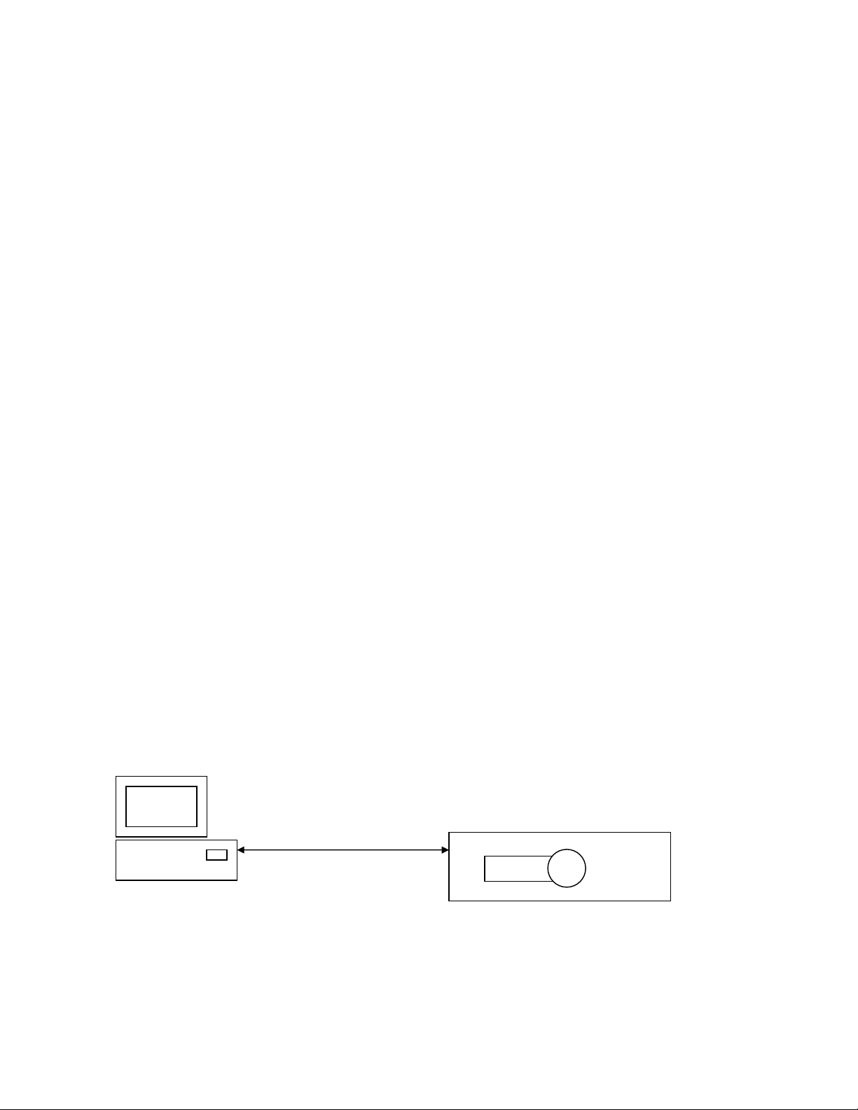
The intention of the MC-4 serial port and protocol communication is for an external connected HOST to
control and obtain status from the MC-4. The protocol has been designed to focus on two specific goals.
The first is HOST uploading and downloading of MC-4 configuration, and system/effect setups. The
second is HOST control of basic user adjustable parameters.(i.e. input, volume, balance…)
HOST
The MC-4 uses simple notification, command, response and acknowledgment packets to have
communication transactions with a given HOST. This protocol is designed for point-to-point
communication between a HOST and MC-4. The MC-4 Protocol is a 3 layered system. The MC-4 serial
protocol allows for the MC-4, or the HOST, to initiate a communication transaction. Most transactions are
initiated by the HOST. MC-4 then responds to the HOST command with either a response or
acknowledgment packet. There are a few asynchronous notifications that MC-4 initiates indicating
Rs-232 Serial
Lexicon MC-4
CD VOL
5
Page 6
Lexicon MC-4 Serial Communications Protocol
system changes. Each transaction initiated must wait for a corresponding response before initiating the
next transmission.
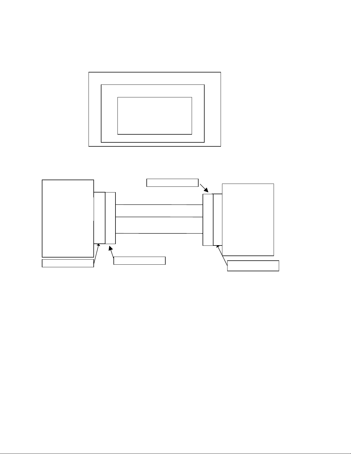
The 3 protocol layers are Physical, Data Link, and Application Layers.
Physical Layer (RS232)
Data Link Layer
Application Layer
4.1 Physical Layer
DB-9 RS232 Connector
MC-4
COM1
Transmit Data
Receive Data
9 Pin D-Shell (female)
Note: The wiring requirements for a 9 pin to 9 pin serial connection are a male to female straight through
cable.
Ground
2
3
5
2
3
5
9 Pin D-Shell (male)
9 Pin D-Shell (female)
Host
Receive Data
2
2
Transmit Data
3
3
Ground
5
5
9 Pin D-Shell (male)
4.2 Serial Port Driver
MC-4 serial port has been setup to operate as follows:
Operating Mode: Full Duplex
Baud rate: 19.2K baud
Data Size: 8 bits (1 byte)
Parity: Odd
Stop Bits: 1
Hardware Handshaking: None
4.3 Errors
The MC-4 will detect parity, framing, and data overrun errors. If any of the physical layer errors are
detected, the complete packet is corrupted and the MC-4 will reset the transaction and begin to look for a
start of packet byte.
6
Page 7
Lexicon MC-4 Serial Communications Protocol
4.4 MC-4 Receive Buffer
The MC-4 has an internal receive buffer. The buffer is 256 Bytes and will transmit a NAK packet with an
error code of DC_ERR_BUFFER_FULL to the HOST if the buffer is full. If the buffer is full, all data
transmitted to the MC-4 will be ignored. Therefore, making the currently transmitted packet, if partially
transmitted invalid.
4.5 MC-4 Hardware Verification
This test verifies the RS232 ports are working by comparing the transmitted signal (at pin 2) to the
received signal (at pin 3). The MC-4 transmits a known test signal just following a power up. The MC-4
monitors the serial port receivers while transmitting the test signal. If the signals are the same, the test
passes. In order to test this circuit, RS232 Wraparound plug(s) are needed and must be installed at the
female D9 connector(s) on the rear panel of the MC-4 labeled “RS232”. The wraparound plug shorts pins
2 to 3, allowing for the MC-4 to receive the signal it is transmitting. Once installed, power cycle the MC-4
and verify the following message is displayed on the FPD:
SERIAL PORT A PASSED
SERIAL PORT B PASSED
This message is displayed for about 2 seconds before entering normal operating mode. If no messages
are displayed, then both wrap tests failed.
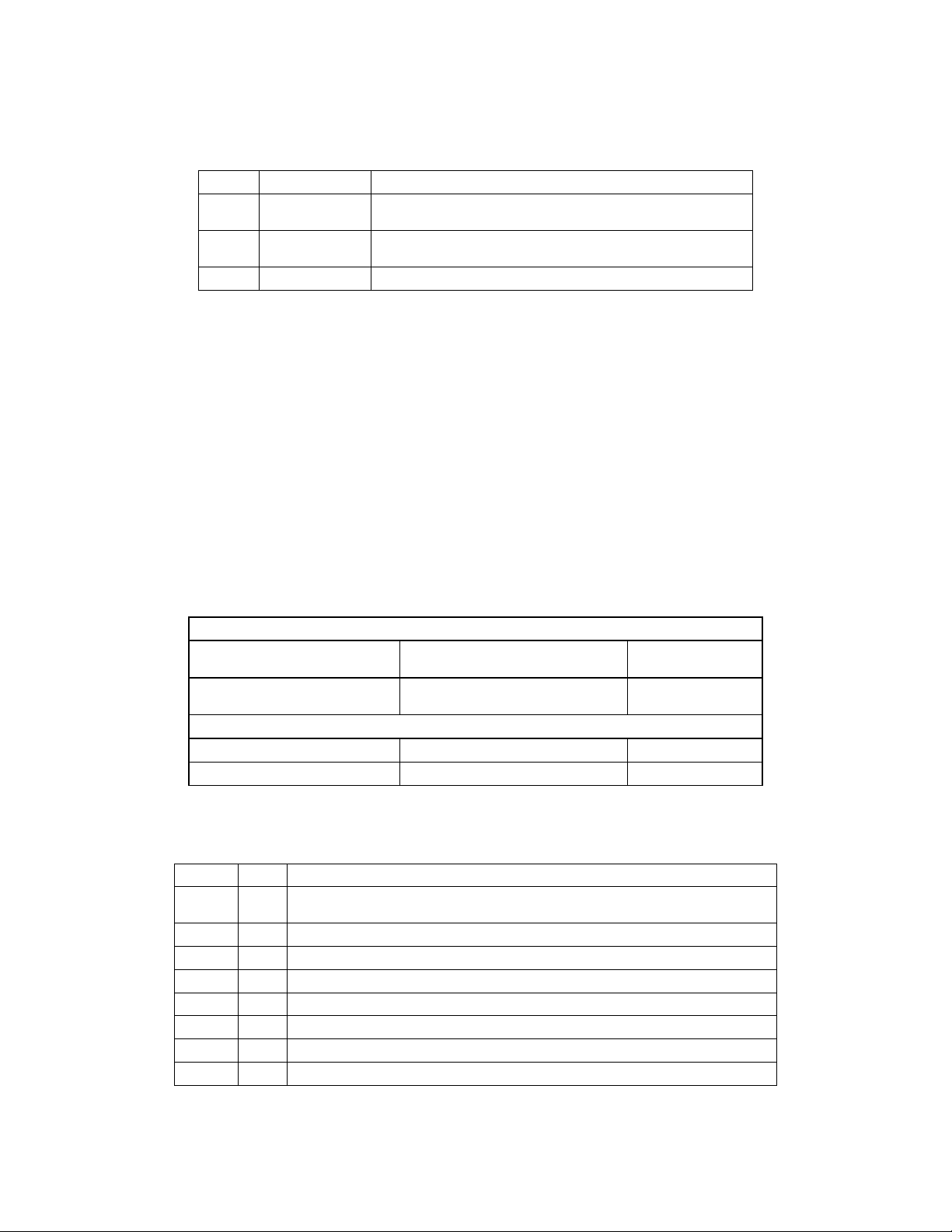
5 Data Link Layer
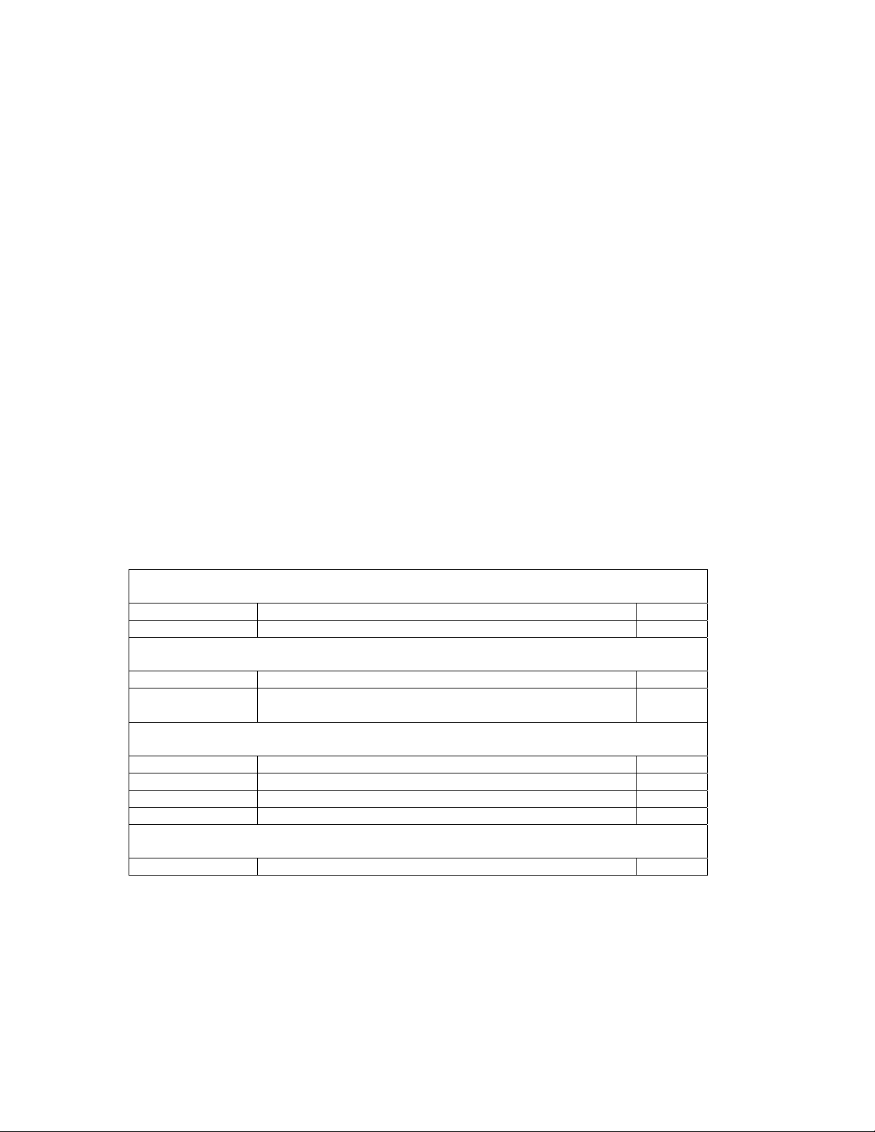
The data link layer is used to define a transmission packet. The layer appends a header and tail that
encloses the transmitted application packet data. The data link header will contain the start of packet
byte and count of bytes to follow. The data link tail will contain the end of packet byte.
Data Link Header:
Byte Number Description Value
First Byte (0) Start of Packet (SOP) 0xF1
Byte (1) DLL Data Count nn
Application Header:
Byte (2) Command nn
Byte (3) APP Data Count (number of application data bytes to
Follow)
Application Data:
Byte (4) Data [0] nn
Byte (5) Data [1] nn
… Data […] nn
Last Data Byte -1 Data [Data Count -1] nn
Data Link Tail:
Last Byte End of Packet (EOP) 0xF2
5.1 Errors
If the number of DLL data bytes received is the same as the data count and an EOP has not been
received, the MC-4 responds by transmitting a NAK packet with an error code
DC_ERR_INVALID_PACKET. The MC-4 then continues to look for a SOP byte and will not process the
erroneous application packet. The HOST can use this as an indicator to retransmit the corrupted packet.
nn
7
Page 8

Lexicon MC-4 Serial Communications Protocol
In addition, each byte of a packet must be received sequentially and within the INTER_PACKET_TIME. If
any of the bytes within a packet transmission exceeds the INTER_PACKET_TIME, the MC-4 will respond
by transmitting a NAK packet with an error code DC_ERR_INVALID_PACKET. The MC-4 then continues
to look for a SOP byte and will not process the erroneous application packet. The HOST can use this as
an indicator to retransmit the corrupted packet.
6 Application Layer
6.1 MC-4 Asynchronous Notification Packets
MC-4 has been designed to transmit the asynchronous notification packets following these system
changes:
1. Power On
2. Entering Standby
3. Front Panel Display update
4. Parameter Value Changes.
The notification packets are defined as follows:
6.1.1 Wakeup Notification
By transmitting the Wakeup Notification, MC-4 indicates the unit has just “powered on” or reset and is
ready to receive host commands. This notification is primarily for the HOST to know the status of the
MC-4.
6.1.1.1 Notification Packet Description
Application Header:
Command DC_WAKEUP 0x01
Data Count 0 0x00
Application Data:
N/A
6.1.1.2 Host Response
The MC-4 does not expect any response from the HOST.
6.1.2 Sleep Notification
By transmitting the Sleep Notification, MC-4 indicates the unit is shutting down into a standby mode.
Because the hard power switch could be activated independently of the MC-4 system software, hard
power down will not be notified. Acknowledgment of the Sleep Notification is not required. This
notification is primarily for the HOST to know the operating status of the MC-4.
6.1.2.1 Notification Packet Description
Application Header:
Command DC_SLEEP 0x02
Data Count 0 0x00
Application Data:
N/A
8
Page 9

Lexicon MC-4 Serial Communications Protocol
6.1.3 Front Panel Display
MC-4 will transmit the front panel display buffer following the update to the MC-4 front panel display. The
MC-4 front panel display is 2 X 20 ASCII character display. The HOST can enable transmission of this
notification message by sending Host Wakeup (
send Host Sleep (
6.3.6 page 14). Transmission of the display buffer is asynchronous to other host/MC-4
6.3.5 page 13). To disable transmission the HOST can
communication and will only transmit following the completion of any communication exchanges in
progress or pending.
6.1.3.1 Notification Packet Description
Application Header:
Command DC_FPD 0x03
Data Count 42 0x2A
Application Data:
Data[0] - Data[20] Line1 ch ch ch… 0x00
Data[21] - Data[41] Line2 ch ch ch … 0x00
6.1.3.2 Data Description
Line1
Data Type: Null (0x00) terminated ASCII character string.
Max Length: DISP_LINE_LENGTH defined in the Protocol Constants table
Appendix D page 38).
(
Line2
Data Type: Null (0x00) terminated ASCII character string.
Max Length: DISP_LINE_LENGTH defined in the Protocol Constants table
Appendix D page 38).
(
The MC-4 includes 8 custom characters that are defined to display increments of a display block.
(i.e. Volume Bar) The custom characters are ASCII character codes 8E - 93(hex). The codes
are used as follows:
'8E' - empty cell
'8F' - left 1 bar
'90' - left 2 bars
'91' - left 3 bars
'92' - left 4 bars
'93' - full cell
6.1.3.3 HOST Response
The MC-4 does not expect any response from the HOST.
6.1.4 MC-4 Parameter Notification by Id
MC-4 will transmit parameter change notifications if they are enabled using the command described in
Set Parameter Notification by Id (
6.3.17 page 26). If a parameter value is changed due to any user action
or system action the MC-4 will transmit the current value of the parameter that is changing.
9
Page 10
Lexicon MC-4 Serial Communications Protocol
6.1.4.1 Command Packet Description
Application Header:
Command MC_PARAM_NOTIFICATION_BY_ID 0x05
Data Count 24 0x18
Application Data:
Data[0] ParamId(LSB) nn
Data[1] ParamId(MSB) nn
Data[2] ParamType nn
Data[3-23] Value[0 -20]
6.1.4.2 Data Description
Same as Set Parameter Value by Id: Data Description (
6.1.4.3 HOST Response
The MC-4 does not expect any response from the HOST.
6.1.4.4 Defaults
The following Parameters Notifications are Enabled in the MC-4 default state:
Parameter MC-4 Parameter Name
Current Mode PARAM.MAIN.EFFECT
Main Zone Mute PARAM.MAIN.MUTE
Main Zone Volume PARAM.MAIN.VOLUME
Main Zone Balance PARAM.MAIN.BALANCE
Main Zone Input Selection PARAM.MAIN.INPUT
Bass PARAM.MAIN.BASS
Treble PARAM.MAIN.TREBLE
Loudness PARAM.MAIN.LOUDNESS
Tilt PARAM.MAIN.TILT
Menu Background On/Off PARAM.OSD.BACKGND
See the V1.00 Parameter ID List (
6.3.12.2 page 20).
page 43) for the Parameter ID definitions.
nn nn
nn…
6.2 Acknowledgment Packets
Acknowledge and No Acknowledge packets are used to communicate transmission, packet and data
validation status. Both the HOST and MC-4 can transmit and receive these packets.
6.2.1 Acknowledge
6.2.1.1 Packet Description
Application Header:
Command DC_ACK 0xE0
Data Count 1 0x01
Application Data:
Data[0] Command nn
10
Page 11
Lexicon MC-4 Serial Communications Protocol
6.2.1.2 Data Description
Command:
DataType: Valid MC-4 command as defined in the Command Codes table
Appendix A page 34).
(
6.2.2 No Acknowledge
6.2.2.1 Packet Description
Appendix B page 35).
6.2.2.2 Data Description
Command:
DataType: Valid MC-4 command as defined in the Command Codes table
ErrorCode:
DataType: Error code as defined in the Error Codes table (
Application Header:
Command DC_NACK 0xE1
Data Count 2 0x02
Application Data:
Data[0] Command nn
Data[1] ErrorCode nn
Appendix A page 34).
(
6.3 Host Initiated Command Packets
The MC-4 serial communication protocol has been designed to respond to the following commands as
described below. Each command is transmitted to the MC-4 with the identified parameters. If the
command is successfully received and processed by the MC-4, the unit will respond with the described
response packet or action.
6.3.1 Reset Unit
Commands the MC-4 to soft reset.
6.3.1.1 Command Packet Description
Application Header:
Command DC_CMD_RESET 0x10
Data Count 0 0x00
Application Data:
N/A
6.3.1.2 MC-4 Response
11
Page 12
Lexicon MC-4 Serial Communications Protocol
The MC-4 will perform an internal reset. After reset, the MC-4 will go through a soft power-up
initialization. This includes transmitting the “Wakeup Notification Packet”. A soft reset does not
reinitialize the MC-4. Nonvolatile RAM is maintained.
6.3.2 Restore Defaults
Commands the MC-4 to restore the system and effect parameters to the factory defaults.
6.3.2.1 Command Packet Description
Application Header:
Command DC_CMD_RESTORE_DEFAULTS 0x13
Data Count 0 0x00
Application Data:
N/A
6.3.2.2 MC-4 Response
The MC-4 will reset, or clear, any saved system and effect parameters in Nonvolatile RAM, and
restore the factory default system and effect parameters. After reset, the MC-4 will go through a
soft power-up initialization. This includes transmitting the “Wakeup Notification Packet”.
6.3.3 Get Custom Name
Request to MC-4 for an effect definition. MC-4 will respond with “Custom Name Packet”.
6.3.3.1 Command Packet Description
Application Header:
Command DC_CMD_GET_CUST_NAME 0x2B
Data Count 0 0x00
Application Data:
N/A
6.3.3.2 Data Description
N/A
6.3.3.3 Custom Name Response Packet
Application Header:
Command DC_RESP_CUST_NAME 0x89
Data Count
Application Data:
Data[0]- Data[DataCount-1] CustomName ch ch ch … 0x00
6.3.3.4 Data Description
CustomName:
Data Type: Null (0x00) terminated ASCII character string.
Max Length: CUSTOM_NAME_LENGTH as defined in the Protocol Constants table
Appendix D page 38).
(
Number of Characters in
CustomName + 1
nn
6.3.4 Set Custom Name
Sets the Custom Name that can be displayed when the unit powers up.
12
Page 13
Lexicon MC-4 Serial Communications Protocol
6.3.4.1 Packet Description
Application Header:
Command DC_CMD_SET_CUST_NAME 0x2C
Data Count
Application Data:
Number of characters in
CustomName + 2
nn
Data[0] CustomNameEnable nn
Data[1]-Data[DataCount-1] CustomName ch ch ch … 0x00
6.3.4.2 Data Description
CustomNameEnable: Enables/Disables the Custom Name Display.
DataType: Boolean
TRUE: CustomName Enabled
FALSE: CustomName Disabled
CustomName:
Data Type: Null (0x00) terminated ASCII character string.
Max Length: CUSTOM_NAME_LENGTH as defined in the Protocol Constants table
Appendix D page 38).
(
6.3.4.3 MC-4 Response
If the custom name enable is TRUE, then the custom name banner is display on “power on”. If
the Custom Name Enable is FALSE, the custom name is not displayed. The CustomName string
is copied to Nonvolatile RAM. The MC-4 will ACK when completed with this command.
6.3.4.4 Data Validation:
No data validation is done on the transmitted data.
6.3.5 Host Wakeup
By transmitting the Wakeup Notification, the Host indicates it has just “powered on” or reset and is ready
to receive MC-4 Notifications or Responses. The Host is assumed to be asleep upon power up of the
MC-4. Host status is maintained during standby.
6.3.5.1 Command Packet Description
Application Header:
Command HOST_WAKEUP 0x11
Data Count 0 0x00
Application Data:
N/A
6.3.5.2 Data Description
N/A
6.3.5.3 MC-4 Response
The MC-4 will respond to this command with an ACK.
13
Page 14
Lexicon MC-4 Serial Communications Protocol
6.3.6 Host Sleep
By transmitting the Sleep command, the Host indicates it has just “powered down” and will no longer
respond to MC-4 Notifications. No Acknowledgment is expected. The Host is assumed to be asleep
upon power up of the MC-4. Host status is maintained during standby.
6.3.6.1 Packet Description
Application Header:
Command HOST_SLEEP 0x12
Data Count 0 0x00
Application Data:
N/A
6.3.6.2 Data Description
N/A
6.3.7 Get Communication Configuration
This command is a request to the MC-4 for the current communications configuration for the serial port
and protocol. The MC-4 responds to this command with a Communication Configuration Packet.
6.3.7.1 Command Packet Description
Application Header:
Command DC_CMD_GET_COM_CONFIG 0x2F
Data Count 0 0x00
Application Data:
N/A
6.3.7.2 Communication Configuration Response Packet
Application Header:
Command DC_RESP_COM_CONFIG 0x8C
Data Count 1 0x01
Application Data:
Data[0] Configuration Register 0 nn
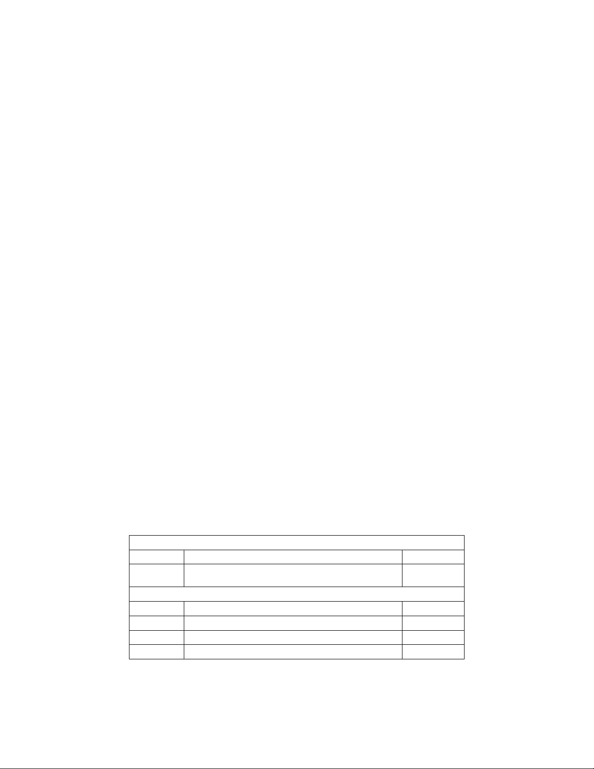
6.3.7.3 Data Description
Data Word Bit Definition
0 0 Acknowledge Enable
0 1 Parameter Change Enable
Acknowledge Enable:
TRUE Indicates the MC-4 will transmit Acknowledge Notification’s to the Host.
FALSE Indicates the MC-4 will not transmit any positive Acknowledge
Notification messages. The MC-4 will always transmit NAK error
notification messages.
Parameter Change Enable:
TRUE Indicates the MC-4 will transmit any parameter change Notification as
specified in the Parameter Change Notification Message.
14
Page 15
Lexicon MC-4 Serial Communications Protocol
FALSE Indicates the MC-4 will not transmit parameter change Notifications.
6.3.8 Set Communication Configuration
The Set Communication Configuration Command allows the serial port user to set up the various serial
port/ protocol configuration parameters.
6.3.8.1 Command Packet Description
Application Header:
Command DC_CMD_SET_COM_CONFIG 0x30
Data Count 1 0x01
Application Data:
Data[0] Configuration Register 0 nn
6.3.8.2 Data Description
Data Word Bit Definition
0 0 Acknowledge Enable
0 1 Parameter Change Enable
Acknowledge Enable:
TRUE Indicates the MC-4 will transmit Acknowledge Notification to the Host.
FALSE Indicates the MC-4 will not transmit any positive Acknowledge
Notification messages. The MC-4 will always transmit NAK error
notification messages.
Parameter Change Enable:
TRUE Indicates the MC-4 will transmit any parameter change Notification as
specified in the Parameter Change Notification Message.
FALSE Indicates the MC-4 will not transmit parameter change Notifications.
6.3.8.3 MC-4 Response
The data values transmitted will be copied over to the registers stored in nonvolatile RAM. The
MC-4 will respond with an ACK Packet.
6.3.9 Set Mute
The Set Mute Command message allows the RS232 users to set/clear the MC-4 mute state directly.
6.3.9.1 Command Packet Description
Application Header:
Command DC_CMD_SET_MUTE 0x31
Data Count 1 0x01
Application Data:
Data[0] Mute State nn
15
Page 16
Lexicon MC-4 Serial Communications Protocol
6.3.9.2 Data Description
MUTE State:
Value Definition Description
0 UNMUTE
1 USER MUTE
The user mute state is set to unmuted. The MC-4
may still be muted for other internal reasons.
The system volume decrements by the specified
user amount as set in the OUTPUT LEVELS Menu.
2 FULL MUTE The system is fully muted.
6.3.9.3 MC-4 Response
The MC-4 will set the mute state according to the value transmitted. The MC-4 may still be full
muted if other conditions require the audio path to be muted. This is only a direct access to the
user mute state.
6.3.9.4 Data Validation
The data value transmitted to the MC-4 will be verified as a valid value. If it is valid, the MC-4 will
set/clear the mute and respond with an ACK Packet. If the data value is invalid, the MC-4 will
respond with a DC_INVALID_DATA error NAK.
6.3.10 Send Display String Command
This command allows the Host to send a 40 character string to the MC-4 for display on the OSD and
Front Panel Display (FPD).
6.3.10.1 Packet Description
Application Header:
Command
Data Count
Application Data:
DC_CMD_SET_DISPLAY_ST
R
Number of characters in the
DisplayStr + 2
0x33
nn
Data[0] DisplayFlags nn
Data[1]-Data[DataCount-1] DisplayStr ch ch ch … 0x00
6.3.10.2 Data Description
Display Command Flags:
Word Bit Definition
0 0
FPD only: If set TRUE, the display string will only be sent to the FPD
device for display.
0 1 Undefined.
0 2 Undefined.
0 3 Undefined.
0 4 Undefined.
0 5 Undefined.
0 6 Undefined.
0 7 Undefined.
16
Page 17

Lexicon MC-4 Serial Communications Protocol
Display String:
Data Type: Null (0x00) terminated ASCII character string.
Max Length: 40 Characters.
6.3.10.3 MC-4 Response
The display string is sent to the OSD and Front Panel Display. The MC-4 will ACK when
completed with this command.
6.3.10.4 Data Validation:
If a string length exceeds the 40 character maximum, the string will be truncated before
displaying and the MC-4 will transmit a DC_NAK command with an error code
DC_INVALID_DATA.
6.3.11 MC-4 Get Parameter Definition by Id
Request to MC-4 for a Parameter Definition by Parameter Id. MC-4 will respond with “MC-4 Parameter
Definition Packet”.
6.3.11.1 Command Packet Description
Application Header:
Command MC_GET_PARAM_BY_ID 0x35
Data Count 2 0x02
Application Data:
Data[0] ParamId(LSB) nn
Data[1] ParamId(MSB) nn
6.3.11.2 Data Description
ParamId:
Data Type: Unsigned 16 bit Integer
Max Value: Max Parameter Count as reported by the MC-4 Unit Configuration
6.3.11.3 Data Validation:
If the ParamId is not a valid Id, the MC-4 will respond with a NAK packet and error code
DC_ INVALID_PARAM_ID.
Response Packet (
6.3.14.2 page 22).
17
Page 18
Lexicon MC-4 Serial Communications Protocol
6.3.11.4 Parameter Definition Response Packet
The following Packet has been defined as follows for the MC-4 V1.00. Future releases may
modify this definition.
Application Header:
Command MC_SYS_PARAM_DEF_PKT 0x8F
Data Count 110 0x6E
Application Data:
Data[0] ParamId(LSB) nn
Data[1] ParamId(MSB) nn
Data[2] ParamType nn
Data[3] MAX Value(LSB) nn
Data[4] MAX Value(MSB) nn
Data[5] MIN Value(LSB) nn
Data[6] MIN Value(MSB) nn
Data[7-27] CurrentValue[0 -20] nn nn nn…
Data[28]-Data[108] Parameter Path ch ch ch … 0x00
Data[108] Read Only nn
6.3.11.5 Data Description
ParamId:
Data Type: Unsigned 16 bit Integer
Max Value: Max Parameter Count as reported by the MC-4 Unit Configuration
Response Packet (
6.3.14.2 page 22).
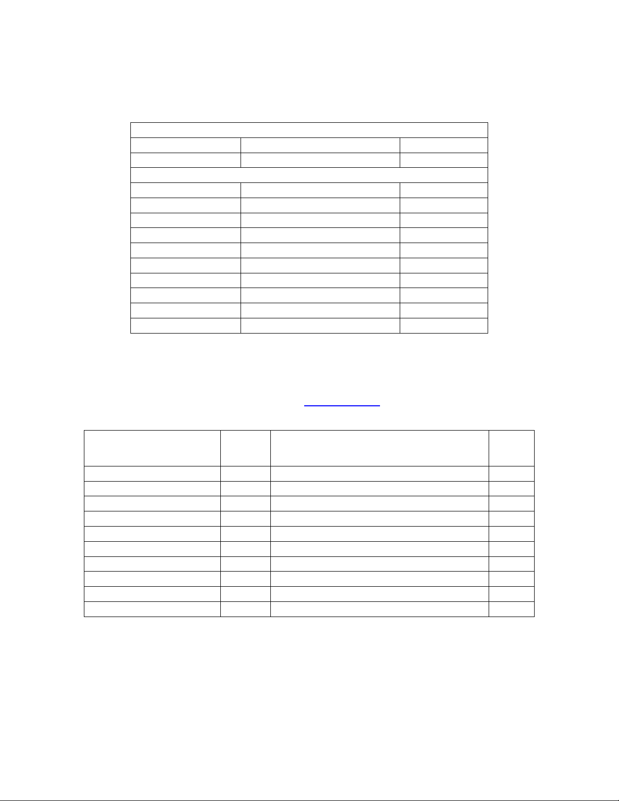
ParamType:
Data
Size
(Bytes)
Param Type Name
Param
Type ID
Type Description
PARAM_TYPE_UINT8 0 Unsigned 8 bit integer (0 to 255) 1
PARAM_TYPE_UINT16 1 Unsigned 16 bit integer (0 to 65535) 2
PARAM_TYPE_CSTR8 2 Zero terminated string of 8 ASCII characters 9
PARAM_TYPE_CSTR13 3 Zero terminated string of 13 ASCII characters 14
PARAM_TYPE_UINT32 4 Unsigned 32 bit integer (0 to 4,294,967,295 ) 4
PARAM_TYPE_BOOLEAN 5 Boolean( 0 to 1) 1
PARAM_TYPE_INT8 6 Signed 8 bit integer (-127 to 128) 1
PARAM_TYPE_BRANCH 7 Parameter Branch N/A
PARAM_TYPE_INT16 8 Signed 16 bit integer (-32,767 to 32,768) 2
PARAM_TYPE_CSTR20 9 Zero terminated string of 20 ASCII characters 21
Data:
The data value transmitted is dependent on the ParamType, as described above. The
CurrentValue is always packed starting at the CurrentValue [0] byte in the packet. For
multi-byte data, the values are packed LSB first(CurrentValue [0]) to MSB(CurrentValue
[0+(num bytes-1)]).
For example: Setting a given signed 16 bit parameter to a value of -300 the data array
would be packed as follows:
18
Page 19
Lexicon MC-4 Serial Communications Protocol
Data[0] = 0xd4
Data[1] = 0xfe
Data[2 - 13] = don't care.
If a parameter's current value is a signed 16 bit parameter with a value of –3, the data
array would be packed as follows:
Data[0] = 0xfd
Data[1] = 0xff
Data[2 - 13] = don't care.
All signed values are in the 2's compliment format.
Max Value:
This is a 16 bit value representing the maximum value for a parameter. Parameter
values exceeding the maximum will be limited to the maximum. This may be a signed or
unsigned value depending on the Parameter Type.
Min Value:
This is a 16 bit value representing the minimum value for a parameter. Parameter values
less than the minimum will be limited to the minimum. This may be a signed or unsigned
value depending on the Parameter Type.
Parameter Path:
This is a zero terminated ASCII character string describing the parameter's name and
path in the units parameter tree structure.
Read Only:
Data Type: Boolean
TRUE: Parameter is read only
FALSE: Parameter is writeable
6.3.12 MC-4 Set Parameter Value by Id
MC-4 Set Parameter by Id command sets the parameter value equal to the value sent in the command
packet, and then runs the appropriate functional changes associated with changing the given parameter.
6.3.12.1 Command Packet Description
Application Header:
Command MC_CMD_SET_SYS_PARAM_VALUE_BY_ID 0x36
Data
Count
Application Data:
24 0x18
Data[0] ParamId(LSB) nn
Data[1] ParamId(MSB) nn
Data[2] ParamType nn
Data[3-23] Value[0 -20] nn nn nn…
19
Page 20

Lexicon MC-4 Serial Communications Protocol
6.3.12.2 Data Description
ParamId:
Data Type: Unsigned 16 bit Integer
Max Value: Max Parameter Count as reported by the MC-4 Unit Configuration
Response Packet (
6.3.14.2 page 22).
ParamType:
Data
Size
(Bytes)
Param Type Name
Param
Type ID
Type Description
PARAM_TYPE_UINT8 0 Unsigned 8 bit integer(0 to 255) 1
PARAM_TYPE_UINT16 1 Unsigned 8 bit integer(0 to 65535) 2
PARAM_TYPE_CSTR8 2 Zero terminated string of 8 ASCII characters 9
PARAM_TYPE_CSTR13 3 Zero terminated string of 13 ASCII characters 14
PARAM_TYPE_UINT32 4 Unsigned 32 bit integer (0 to 4,294,967,295 ) 4
PARAM_TYPE_BOOLEAN 5 Boolean (0 to 1) 1
PARAM_TYPE_INT8 6 Signed 8 bit integer (-127 to 128) 1
PARAM_TYPE_BRANCH 7 Parameter Branch N/A
PARAM_TYPE_INT16 8 Signed 16 bit integer (-32,767 to 32,768) 2
PARAM_TYPE_CSTR20 9 Zero terminated string of 20 ASCII characters 21
Value:
The data value transmitted is dependent on the ParamType, as described above. The
Data Value is always packed starting at the Value[0] byte in the packet. For multi-byte
data, the values are packed LSB first(Value[0]) to MSB(Value[0+(num bytes-1)]). For
example: Setting a given signed 16 bit parameter to a value of -300 the data array would
be packed as follows:
Value[0] = 0xd4
Value[1] = 0xfe
Value[2 - 13] = don't care.
All signed values are in the 2's compliment format.
6.3.12.3 Data Validation:
The ParamId must be a valid Parameter. The ParamType must be valid for the given ParamId. If
either of these conditions is not true the MC-4 will respond with a NAK packet and error code DC
_ INVALID_PARAM_ID. The data value size cannot exceed the size of a given data type. A
value that does exceed the size of a given data type will be truncated to the appropriate size.
The ParamType transmitted must match the ParamType for the Parameter being transmitted, as
per the Parameter Definition as transmitted by the MC_SYS_PARAM_DEF_PKT. If the types do
not match, the MC-4 will transmit a NAK packet with a DC_INVALID_INPUT error code. The
MC-4 will transmit a NAK packet with a DC_ERR_READ_ONLY error code for read only
parameters.
20
Page 21

Lexicon MC-4 Serial Communications Protocol
6.3.13 MC-4 Set Parameter Value by Id, No Run
MC-4 Set Parameter by Id command sets the parameter value equal to the value sent in the command
packet and does not run the appropriate functional changes associated with changing the given
parameter.
6.3.13.1 Command Packet Description
Application Header:
Command MC_CMD_SET_SYS_PARAM_VALUE_BY_ID_NO_RUN 0x37
Data Count 24 0x18
Application Data:
Data[0] ParamId(LSB) nn
Data[1] ParamId(MSB) nn
Data[2] ParamType nn
Data[3-23] Value[0 -20] nn nn nn…
6.3.13.2 Data Description
Same as MC-4 Set Parameter Value by Id: Data Description (
6.3.12.2 page 20).
6.3.14 MC-4 Get Unit Configuration
Request to MC-4 for its current unit configuration. MC-4 will respond with “Unit Configuration Packet”.
The HOST should use this information to determine if any information saved by the HOST is current.
6.3.14.1 Command Packet Description
Application Header:
Command MC_CMD_GET_CONFIG 0x38
Data Count 0 0x00
Application Data:
N/A
21
Page 22

Lexicon MC-4 Serial Communications Protocol
6.3.14.2 MC-4 Unit Configuration Response Packet
Application Header:
Command MC_RESP_UNIT_CONFIG 0x91
Data Count 30 0x1E
Application Data:
Data[0] ProductId nn
Data[1] Software Type nn
Data[2] Software Level nn
Data[3] Software Major Revision nn
Data[4] Software Minor Revision nn
Data[5] Protocol Major Revision nn
Data[6] Protocol Minor Revision nn
Data[7] Parameter Count Low(LSB) nn
Data[8] Parameter Count High(MSB) nn
Data[9] Effect Count nn
Data[10] TimeStamp[0] ch
Data[11] TimeStamp[1] ch
Data[12] TimeStamp[2] ch
Data[13] TimeStamp[3] ch
Data[14] TimeStamp[4] ch
Data[15] TimeStamp[5] ch
Data[16] TimeStamp[6] ch
Data[17] TimeStamp[7] ch
Data[18] TimeStamp[8] ch
Data[19] TimeStamp[9] ch
Data[20] TimeStamp[10] ch
Data[21] TimeStamp[11] ch
Data[22] TimeStamp[12] ch
Data[23] TimeStamp[13] ch
Data[24] TimeStamp[14] ch
Data[25] TimeStamp[15] 0x00
Data[26] SerialNumber(LSB) nn
Data[27] SerialNumber nn
Data[28] SerialNumber nn
Data[29] SerialNumber(MSB) nn
22
Page 23

Lexicon MC-4 Serial Communications Protocol
6.3.14.3 Data Description
ProductId:
This unsigned 8 bit value describes the product.
Product ID
Lexicon DC-2 1
Lexicon MC-1 2
JBL Synthesis SDP-3 3
Lexicon MC-12 4
JBL Synthesis SDP-40 5
Lexicon MC-8 6
JBL SDP-5 7
Lexicon RV8 8
Lexicon MC-4 9
JBL AV1 10
Software Type:
An unsigned 8 bit value indicating the current configuration of the unit’s software. The
following table shows the values assigned to the available types:
SW Type
THX 1
AC3 2
DTS 3
COMPLETE 4
BOOTROM 5
Software Level:
The following table shows the values assigned to the possible software levels:
SW Level
RELEASED 0
PRE_ALPHA 1
ALPHA 2
BETA 3
GAMMA 4
UNSUPPORTED 5
*Note: SW level indicates the status of the MC-4 internal application software.
Software Major Revision:
An unsigned 8 bit integer value indicating the unit’s major software version. The host
should use this information to determine if new effects, effect parameters, or system
parameters have been added or removed.
23
Page 24

Lexicon MC-4 Serial Communications Protocol
Software Minor Revision:
An unsigned 8 bit integer value indicating this unit’s minor software version. Indicates the
unit’s software operation has changed but effects, effect parameters, or system
parameters have not changed.
Protocol Major Revision:
An unsigned 8 bit integer value indicating the serial communication protocol major
version. The host should use this value to determine if new commands, notifications, or
response packets have been added or deleted from this specification.
Protocol Minor Revision:
An unsigned 8 bit integer value indicating the serial communication protocol minor
version. The host should use this value to determine if the existing commands,
notifications, or response packets have changed in this specification
Parameter Count:
An unsigned 16 bit integer value indicating the maximum number of parameters for this
version of software. All Parameters are sequentially ordered within the unit so cycling
from ParamId 0 to ParamId = Parameter Count -1 allows for the host system to learn the
Parameter definitions for all Parameters defined for a given software version. The 16 bit
value is packed LSB followed by the MSB.
Total Number of Effects:
An unsigned 8 bit integer value indicating the maximum number of effects available for
this version of software.
TimeStamp:
A null terminated ASCII text string describing the build date and time of the current
software build. The Format of this text string is:
“yy/mm/dd(sp)hh:mm”
yy- is the last two digits of the year (i.e. year 2001=01, year 2002 = 02)
mm - is the month
dd- is the day
(sp) - is an ASCII space character (0x20)
hh - is the hour
mm - is the minute
SerialNumber:
An unsigned 32 bit integer holding the unique value of the current unit.
6.3.15 MC-4 Send IR Command
This command allows the HOST to transmit IR command key codes to the MC-4.
6.3.15.1 Command Packet Description
Application Header:
Command MC_CMD_IR 0x39
Data Count 1 0x01
Application Data:
Data[0] KeyCode nn
24
Page 25

Lexicon MC-4 Serial Communications Protocol
6.3.15.2 Data Description
KeyCode:
Data Type: Unsigned 8 bit integer.
Valid Values: MC-4 IR Codes (
Appendix C page 36)
6.3.15.3 MC-4 Response
The KeyCode is processed as a valid IR code. No acknowledgment will be sent from the MC-4.
6.3.15.4 Data Validation
The KeyCode data will be verified as a legal IR code. If the Code is not valid, the MC-4 will not
respond.
6.3.16 MC-4 Get Parameter Value by Id
Request to MC-4 for the current value of a given parameter. The MC-4 will respond with a “Parameter
Value Packet”.
6.3.16.1 Command Packet Description
Application Header:
Command MC_CMD_GET_PARAM_VALUE_BY_ID 0x3A
Data Count 2 0x02
Application Data:
Data[0] ParamId (LSB) nn
Data[1] ParamId (MSB) nn
6.3.16.2 Data Description
ParamId:
Data Type: Unsigned 16 bit integer.
Max: Max Parameter Count as reported by the MC-4 Unit Configuration
Response Packet (
6.3.14.2 page 22)
6.3.16.3 Data Validation
If ParamId exceeds its maximum value, the MC-4 will ignore the command and transmit a
DC_NAK command with an error code DC_INVALID_PARAM_ID.
6.3.16.4 MC-4 Value String Response Packet
Application Header:
Command MC_RESP_PARAM_VALUE 0x92
Data Count 24 0x18
Application Data:
Data[0] ParamId (LSB) nn
Data[1] ParamId (MSB) nn
Data[2] ParamType nn
Data[3-23] Value[0 -20] nn nn nn…
6.3.16.5 Data Description
Same as MC-4 Set Parameter Value by Id: Data Description (
6.3.12.2 page 20).
25
Page 26

Lexicon MC-4 Serial Communications Protocol
6.3.17 MC-4 Set Parameter Notification by Id
Request to MC-4 to enable or disable transmission of the MC-4 parameter change notification for a given
parameter.
6.3.17.1 Command Packet Description
Application Header:
Command MC_CMD_SET_PARAM_NOTIFICATION_BY_ID 0x3B
Data Count 3 0x03
Application Data:
Data[0] ParamId (LSB) nn
Data[1] ParamId (MSB) nn
Data[2] Enable/Disable nn
6.3.17.2 Data Description
ParamId:
Data Type: Unsigned 16 bit integer.
Max: Max Parameter Count as reported by the Unit Configuration Response
Packet in MC-4 Unit Configuration Response Packet (
6.3.14.2 page 22)
Enable/Disable:
Data Type: Boolean
TRUE: Enable transmission of parameter notification
FALSE: Disable transmission of parameter notification
6.3.17.3 Data Validation
If ParamId exceeds its maximum value, the MC-4 will ignore the command and transmit a
DC_NAK command with an error code DC_INVALID_PARAM_ID.
6.3.17.4 MC-4 Response
If a parameter has been enabled for notification, the MC-4 will transmit its current value whenever
it has been changed due to any user or system action, see MC-4 Parameter Notification by Id
notification packet (
6.1.4 page 9).
6.3.18 MC-4 Parameter Get Value String by Id
Request to MC-4 for the string representation of a given value for a given parameter. The MC-4 will
respond with a “Value String Response Packet”.
6.3.18.1 Command Packet Description
Application Header:
Command MC_CMD_PARAM_GET_VALUE_STRING_BY_ID 0x3C
Data Count 23 0x17
Application Data:
Data[0] ParamId (LSB) nn
Data[1] ParamId (MSB) nn
Data[2] - Data[22] Value[0] - Value[20] nn nn nn ..
26
Page 27

Lexicon MC-4 Serial Communications Protocol
6.3.18.2 Data Description
ParamId:
Data Type: Unsigned 16 bit integer.
Max: Max Parameter Count as reported by the MC-4 Unit Configuration
Response Packet (
6.3.14.2 page 22).
Value:
See
MC-4 Set Parameter Value by Id: Data Description (6.3.12.2 page 20).
6.3.18.3 Data Validation
If ParamId exceeds its maximum value, the MC-4 will ignore the command and transmit a
DC_NAK command with an error code DC_INVALID_PARAM_ID.
6.3.18.4 MC-4 Value String Response Packet
Application Header:
Command MC_RESP_VALUE_STRING 0x93
Data Count Number of Characters in Value String + 1 nn
Application Data:
Data[0] - Data[20] Value String ch ch ch … 0x00
6.3.18.5 Data Description
Value String:
Data Type: Null (0x00) terminated ASCII string.
Max Length: 21 (20 characters plus terminating Null)
6.3.19 MC-4 Clear All Parameter Notifications
Request to MC-4 to disable all MC-4 parameter notifications.
6.3.19.1 Command Packet Description
Application Header:
Command MC_CMD_CLEAR_ALL_PARAM_NOTIFICATIONS 0x3D
Data Count 0 0x00
Application Data:
N/A
6.3.20 MC-4 Get System Status
Request to MC-4 for its current system status. MC-4 will respond with “System Status Packet”.
6.3.20.1 Command Packet Description
Application Header:
Command MC_CMD_GET_SYS_STATUS 0x3E
Data Count 0 0x00
Application Data:
N/A
27
Page 28

Lexicon MC-4 Serial Communications Protocol
6.3.20.2 System Status Response Packet
Application Header:
Command MC_RESP_SYS_STATUS 0x94
Data Count 10 0x0A
Application Data:
Data[0] System Volume nn
Data[1] Current Input nn
Data[2] Current Effect Id nn
Data[3] Current Input Sample Rate nn
Data[4] Current Input Format nn
Data[5] Mute Active nn
Data[6] Effect Bypass nn
Data[7] Left/Right Balance nn
Data[8] Front/Back Balance nn
Data[9] Video Sync nn
6.3.20.3 Data Description
System Volume:
Data Type: Signed 8 bit integer (2’s compliment)
Max: +12 (0x0C) (12 dB)
Min: -80 (0xB0) (-80 dB)
Current Input:
Data Type: Unsigned 8 bit integer
Definition/Conversion: MC-4 Input Ids (
Appendix F page 40)
Current Effect Id:
Data Type: Unsigned 8 bit integer
Definition/Conversion: MC-4 Mode Ids (
Appendix E page 39)
Current Input Sample Rate:
Data Type: Unsigned 8 bit integer.
SAMPLE RATE
RATE_UNKNOWN 0
RATE_44 1
RATE_48 2
RATE_88 3
RATE_96 4
28
Page 29

Lexicon MC-4 Serial Communications Protocol
Current Input Format:
Data Type: Unsigned 8 bit integer.
DATA STREAM TYPE
DATA_TYPE_UNKNOWN 0
DATA_TYPE_BYPASS 1
DATA_TYPE_ANALOG 2
DATA_TYPE_PCM 3
DATA_TYPE_DD 4
DATA_TYPE_DTS 5
DATA_TYPE_NOISE 6
Mute Active:
Data Type: Boolean.
TRUE: System Mute is Active
FALSE: System is unmuted.
Effect Bypass:
Data Type: Boolean
TRUE: Effect Bypass is Active
FALSE: Effect Bypass is Inactive
Left/Right Balance:
Data Type: Signed 8 bit integer (2’s compliment)
Max: 16 (0x10) (Full Right)
Min: -16 (0xF0) (Full Left)
Front/Back Balance:
Data Type: Signed 8 bit integer (2’s compliment)
Max: 16 (0x10) (Full Front)
Min: -16 (0xF0) (Full Back)
Video Sync:
Data Type: Boolean.
TRUE: MC-4 has detected Video Sync for current video input
FALSE: MC-4 can not detect Video Sync for the current video input
6.3.21 MC-4 Set System Volume
This command is a request to the MC-4 to set the system volume with the value in this packet.
6.3.21.1 Command Packet Description
Application Header:
Command MC_CMD_SET_SYS_VOLUME 0x40
Data Count 1 0x01
Application Data:
Data[0] Value nn
29
Page 30

Lexicon MC-4 Serial Communications Protocol
6.3.21.2 Data Description
Value:
Data Type: Signed 8 bit integer (2’s compliment)
Max: +12 (0x0C) (12 dB)
Min: -80 (0xB0) (-80 dB)
6.3.21.3 MC-4 Response
The MC-4 will assign the value from the packet to the system volume.
6.3.21.4 Data Validation
If a value is passed that exceeds the maximum value of that parameter, the MC-4 will ignore the
command and transmit a DC_NAK command with an error code DC_INVALID_DATA.
6.3.22 MC-4 Set Main Balance
Commands MC-4 to set the system balance to the value in this packet.
6.3.22.1 Command Packet Description
Application Header:
Command DC_CMD_SET_SYS_BALANCE 0x41
Data Count 1 0x01
Application Data:
Data[0] Value nn
6.3.22.2 Data Description
Value:
Data Type: Signed 8 bit integer (2’s compliment)
Max: +16 (0x10) (Full Right)
Min: -16 (0xF0) (Full Left)
6.3.22.3 MC-4 Response
The MC-4 will assign the value from the packet to the system balance.
6.3.22.4 Data Validation
If a value is passed that exceeds the maximum value of that parameter, the MC-4 will ignore the
command and transmit a DC_NAK command with an error code DC_INVALID_DATA.
6.3.23 MC-4 Set Fader
Commands MC-4 to set the front/back balance to the value in this packet.
6.3.23.1 Packet Description
Application Header:
Command
Data Count
MC_CMD_SET_FRONT_BACK_BALANCE 0x42
1 0x01
Application Data:
Data[0]
Value nn
30
Page 31

Lexicon MC-4 Serial Communications Protocol
6.3.23.2 Data Description
Value:
Data Type: Signed 8 bit integer (2’s compliment)
Max: +16 (0x10) (Full Front)
Min: -16 (0xF0) (Full Back)
6.3.23.3 MC-4 Response
The MC-4 will assign the value from the packet to the front/back balance.
6.3.23.4 Data Validation
If a value is passed that exceeds the maximum value of that parameter, the MC-4 will ignore the
command and transmit a NAK command with an error code DC_INVALID_DATA.
6.3.24 MC-4 Set Active Effect by Id
This command requests the MC-4 to set the active effect to the value in this packet.
6.3.24.1 Command Packet Description
Application Header:
Command MC_CMD_SET_EFFECT 0x43
Data Count 1 0x01
Application Data:
Data[0] EffectId nn
6.3.24.2 Data Description
EffectId:
Data Type: Unsigned 8 bit integer
Definition/Conversion: MC-4 Mode Ids (
Appendix E page 39)
6.3.24.3 MC-4 Response
The MC-4 will load the desired effect.
6.3.24.4 Data Validation
If a value is passed that exceeds the maximum value of that parameter, the MC-4 will ignore the
command and transmit a NAK command with an error code DC_INVALID_DATA.
6.3.25 MC-4 Get Input Name by Id
This command is a request to MC-4 for the custom input name. MC-4 will respond with “Input Name
Packet”.
6.3.25.1 Command Packet Description
Application Header:
Command MC_CMD_GET_INPUT_NAME 0x47
Data Count 1 0x01
Application Data:
Data[0] InputId nn
31
Page 32

Lexicon MC-4 Serial Communications Protocol
6.3.25.2 Data Description
InputId:
Data Type: Unsigned 8 bit Integer
Definition/Conversion: MC-4 Input Ids (
Appendix F page 40)
6.3.25.3 Data Validation
The InputId must be a valid Input number. If it is not, the MC-4 will respond with a NAK packet
and error code DC_INVALID_INPUT.
6.3.25.4 Input Name Response Packet
Application Header:
Command MC_RESP_INPUT_NAME 0x96
Data Count
Application Data:
Number of Characters in
InputName + 2
nn
Data[0] InputId nn
Data[1]- Data[DataCount-1] InputName ch ch ch … 0x00
6.3.25.5 Data Description
InputId:
Data Type: Unsigned 8 bit Integer
Definition/Conversion: MC-4 Input Ids (
Appendix F page 40)
InputName:
Data Type: Null (0x00) terminated ASCII character string.
Max Length: INPUT_NAME_LENGTH defined in Protocol Constants table
Appendix D page 38)
(
6.3.26 MC-4 Set Input Name by Id
Sets an Input Name to the transmitted value for a given input.
6.3.26.1 Command Packet Description
Application Header:
Command MC_CMD_SET_INPUT_NAME 0x48
Data Count
Application Data:
Number of characters in
InputName + 2
Data[0] InputId 0 to 7
Data[1]-Data[DataCount-1] InputName ch ch ch ... 0x00
6.3.26.2 Data Description
InputId:
Data Type: Unsigned 8 bit Integer
Description/Conversion: MC-4 Input Ids (
Appendix F page 40)
InputName:
Data Type: Null (0x00) terminated ASCII character string.
Max Length: INPUT_NAME_LENGTH defined in Protocol Constants table
Appendix D page 38)
(
nn
32
Page 33

Lexicon MC-4 Serial Communications Protocol
6.3.26.3 MC-4 Response
MC-4 will copy the InputName to the given input.
6.3.26.4 Data Validation
The InputId must be a valid Input Id. If it is not, the MC-4 will respond with a NAK packet and
error code DC_INVALID_INPUT. If the InputName string exceeds the INPUT_NAME_LENGTH,
the MC-4 will truncate the string to the INPUT_NAME_LENGTH.
33
Page 34

Lexicon MC-4 Serial Communications Protocol
Appendix A: Command Codes
Notifications:
DC_NO_CMD 0x00
DC_WAKEUP 0x01
DC_SLEEP 0x02
DC_FPD 0x03
Host Commands:
DC_CMD_RESET 0x10
HOST_WAKEUP 0x11
HOST_SLEEP 0x12
DC_CMD_RESTORE_DEFAULTS 0x13
DC_CMD_GET_FPD_CTRL 0x29
DC_CMD_SET_FPD_CTRL 0x2A
DC_CMD_GET_CUST_NAME 0x2B
DC_CMD_SET_CUST_NAME 0x2C
DC_CMD_GET_COM_CONFIG 0x2F
DC_CMD_SET_COM_CONFIG 0x30
DC_CMD_SET_MUTE 0x31
DC_CMD_SET_OUTPUT_ADJ 0x32
DC_CMD_SEND_DISPLAY_STR 0x33
MC_CMD_GET_SYS_PARAM_BY_ID 0x35
MC_CMD_SET_SYS_PARAM_VALUE_BY_ID 0x36
MC_CMD_SET_SYS_PARAM_VALUE_BY_ID_NO_RUN 0x37
MC_CMD_GET_CONFIG 0x38
MC_CMD_IR 0x39
Responses:
DC_RESP_FPD_CTRL_STATUS 0x88
DC_RESP_CUST_NAME 0x89
DC_RESP_INPUT_NAME 0x8A
DC_RESP_PEEK_VALUE 0x8B
DC_RESP_COM_CONFIG 0x8C
MC_RESP_SYS_PARAM_DEF 0x8F
MC_RESP_UNIT_CONFIG 0x91
Acknowledgments:
DC_ACK 0xE0
DC_NAK 0xE1
34
Page 35

Lexicon MC-4 Serial Communications Protocol
Appendix B: Error Codes
Error Code(Hex)
NO_ACK 0x00
DC_NO_ERROR 0x01
DC_ERR_PARITY 0x02
DC_ERR_FRAMING 0x03
DC_ERR_OVERRUN 0x04
DC_ERR_INVALID_PACKET 0x05
DC_ERR_TIME_OUT 0x06
DC_ERR_BUFFER_FULL 0x07
DC_INVALID_COUNT 0x10
DC_INVALID_CMD 0x11
DC_INVALID_DATA 0x12
DC_INVALID_ADDRESS 0x13
DC_INVALID_EFFECT_ID 0x14
DC_INVALID_PARAM_ID 0x15
DC_INVALID_NAME 0x16
DC_INVALID_INPUT 0x17
DC_ERR_READ_ONLY 0x18
35
Page 36

Lexicon MC-4 Serial Communications Protocol
Appendix C: MC-4 IR Codes
KEY
1 STANDBY 0x19 MAIN_OFF 0x99 ZONE_OFF 0x59
2 ON 0x18 Reserved 0x98 Reserved 0x58
3 FP 0x04 BAL_CENTER 0x84 ZONE_BAL_CENTER 0x44
4 BLUE 0x03 TRIGGER1_OFF 0x83 EQ_OFF 0x43
5 LIGHT None LIGHT None LIGHT None
6 OSD 0x02 TRIGGER1_ON 0x82 Reserved 0x42
7 STAT 0x1C INPUT_STATUS 0x9C ZONE_STATUS 0x5C
8 UP_ARROW 0x01 FADER_FRONT 0x81 SUB_ADJ_INCR 0x41
9 LEFT_ARROW_DONE 0x0A BAL_LEFT 0x8A ZONE_BAL_LEFT 0x4A
10 Reserved Reserved Reserved
11 RIGHT_ARROW_SELECT 0x08 BAL_RIGHT 0x88 ZONE_BAL_RIGHT 0x48
12 DN_ARROW 0x1D FADER_REAR 0x9D SUB_ADJ_DECR 0x5D
13 MUTE 0x15 FULL_MUTE 0x95 ZONE_MUTE 0x55
14 MODE_INCR 0x1A VOL_N15DB 0x9A ZONE_VOL_N15DB 0x5A
15 MODE_DECR 0x1B VOL_N30DB 0x9B ZONE_VOL_N30DB 0x5B
16 VOL_INCR 0x17 VOL_03DB 0x97 ZONE_VOL_INCR 0x57
17 VOL_DECR 0x16 VOL_N03DB 0x96 ZONE_VOL_DECR 0x56
18 MAIN_DVD_1 0x20 BASS_INCR 0xA0 ZONE_DVD_1 0x60
19 MAIN_DVD_2 0x21 TREBLE_INCR 0xA1 ZONE_DVD_2 0x61
20 MAIN_SAT 0x24 TILT_INCR 0xA4 ZONE_SAT 0x64
21 MAIN_VCR 0x25 LOUDNESS_ON 0xA5 ZONE_VCR 0x65
22 MAIN_TV 0x23 BASS_DECR 0xA3 ZONE_TV 0x63
23 MAIN_CD 0x26 TREBLE_DECR 0xA6 ZONE_CD 0x66
24 MAIN_TUNER 0x2A TILT_DECR 0xAA ZONE_TUNER 0x6A
25 MAIN_AUX 0x2B LOUDNESS_OFF 0xAB ZONE_AUX 0x6B
26 Reserved Reserved Reserved
27 Reserved Reserved Reserved
28 Reserved Reserved Reserved
29 Reserved Reserved Reserved
30 LOGIC7_LOGO 0x0D PANORAMA 0x8D Reserved 0x4D
31 DOLBY_LOGO 0x0C DOLBY_EX_TOGGLE 0x8C Reserved 0x4C
32 DTS_LOGO 0x0F DTS_ES_TOGGLE 0x8F Reserved 0x4F
33 THX_LOGO 0x0B THX_EX_TOGGLE 0x8B Reserved 0x4B
34 MUSIC 0x10 MUSIC_SURROUND 0x90 Reserved 0x50
35 TV_L_LOGO 0x0E MONO_LOGIC 0x8E Reserved 0x4E
36 MAIN_TOGGLE_7_5 0x1E MAIN_SRC_MODE 0x9E Reserved 0x5E
37 MAIN_2_CHANNEL 0x1F BYPASS 0x9F Reserved 0x5F
38 Reserved Reserved Reserved
39 Reserved Reserved Reserved
40 Reserved Reserved Reserved
41 Reserved Reserved Reserved
FUNCTION
DATA
(hex)
FUNCTION
DATA
(hex)
FUNCTION
DATA
(hex)
36
Page 37

Lexicon MC-4 Serial Communications Protocol
Additional Ir Codes(V1.0)
Mode Code(hex) Mode Code(hex)
DIRECT_LOGIC7_IR 0xAC DIRECT_DTS_LOGIC7_IR 0xEC
DIRECT_TV_LOGIC_IR 0xAD DIRECT_DTS_MUSIC_IR 0xED
DIRECT_MUSIC_LOGIC_IR 0xAE DIRECT_DTS_2CHANNEL_IR 0xEE
DIRECT_2CHAN_SURROUND_IR 0xAF DIRECT_DTS_IR 0xEF
DIRECT_2_CHANNEL_IR 0xB0 DIRECT_DTS_THX_IR 0xF0
DIRECT_MONO_LOGIC_IR 0xB1
DIRECT_MONO_SURROUND_IR 0xB2
DIRECT_MONO_IR 0xB3
DIRECT_PROLOGIC_IR 0xB4
DIRECT_PROLOGIC2_IR 0xB5
DIRECT_PL2MUSIC_IR 0xB6 DIRECT_NIGHTCLUB_IR 0xF6
DIRECT_THX_CINEMA_IR 0xB7 DIRECT_CONCERT_HALL_IR 0xF7
DIRECT_DTS_NEO_FILM_IR 0xB8 DIRECT_CHURCH_IR 0xF8
DIRECT_DTS_NEO_MUSIC_IR 0xB9 DIRECT_CATHEDRAL_IR 0xF9
DIRECT__51_LOGIC7_IR 0xBA DIRECT_MUSIC_SURR_IR 0xFA
DIRECT__51_TV_LOGIC_IR 0xBB DIRECT__51_AD_THX_MUSIC_IR 0xFB
DIRECT__51_MUSIC_IR 0xBC DIRECT_DTS_THX_MUSIC_IR 0xFC
DIRECT__51_THX_IR 0xBD DIRECT__51_THX_MUSIC_IR 0xFD
DIRECT_DOLBY_DIGITAL_IR 0xBE DIRECT_PANORAMA_IR 0xFE
DIRECT__51_2CHANNEL_IR 0xBF
DIRECT__51_MONO_LOGIC_IR 0xC0
DIRECT__51_MONO_SURROUND_IR 0xC6
DIRECT__51_MONO_IR 0xC7
37
Page 38

Lexicon MC-4 Serial Communications Protocol
Appendix D: Protocol Constants
Constant Value (Dec) Units
FPD_LINE_LENGTH 20 Chars
PARAM_NAME_LENGTH 13 Chars
CUSTOM_NAME_LENGTH 20 Chars
INPUT_NAME_LENGTH 8 Chars
PARAM_PATH_LENGTH 80 Chars
INTER_PACKET_TIME 200 mSec
SOP 0xF1 Hex
EOP 0xF2 Hex
38
Page 39

Lexicon MC-4 Serial Communications Protocol
Appendix E: MC-4 Mode Ids
MC-4 Mode Name
NONE 0 0
N/A 1 1
Internal Noise 2 2
L7 Film 3 3
L7 TV 4 4
L7 Music 5 5
2-Ch Surround 6 6
2-Channel 7 7
Mono Logic 8 8
Mono Surround 9 9
Mono 10 0A
5.1 L7 Film 17 11
5.1 L7 TV 18 12
5.1 L7 Music 19 13
THX(ex) 20 14
Dolby Digital 21 15
5.1 2-Channel 22 16
5.1 Mono Logic 23 17
5.1 Mono Surround 24 18
5.1 Mono 25 19
dts L7 Film 26 1A
dts L7 Music 27 1B
dts 2-Channel 28 1C
dts 29 1D
dts THX 30 1E
2ch Analog Bypass 31 1F
5.1 Analog Bypass 32 20
Nightclub 41 29
Concert Hall 42 2A
Church 43 2B
Cathedral 44 2C
L7 Music Surround 45 2D
Panorama 50 32
PLII + THX 14 0E
PLII Movie 12 0C
PLII Music 13 0D
PL + THX 51 33
Pro Logic 11 0B
DtsNEO6 + THX 52 34
DtsNEO6 Cin 15 0F
DtsNEO6 Music 16 10
THX Music (5.1) 48 30
Dts THX Music 47 2F
MC-4
Effect ID
MC-4 Effect
ID (hex)
39
Page 40

Lexicon MC-4 Serial Communications Protocol
Appendix F: MC-4 Input Ids
MC-4 Input Name MC-4 Input Id
OFF 0
DVD1 1
DVD2 2
TV 3
SAT 4
VCR 5
CD 6
TUNER 7
AUX 8
Application Notes and Examples
6.4 Box initializations
6.4.1 MC-4
When the MC-4 is powered on, it will initialize the serial port, transmit the DC_WAKEUP Packet, and look
for an ACK from the HOST. Currently, if an ACK is not received, the MC-4 continues to operate. This
message is mostly for the HOST to know if the MC-4 is in an operational state.
6.4.2 HOST
When the HOST issues a HOST_WAKEUP Packet, the MC-4 responds with an ACK and then transmits
the current FPD buffer with a DC_FPD notification. If the Host issues a HOST_WAKEUP command and
does not receive the ACK, it should assume it is not connected or the MC-4 is not capable of responding
on the RS232 and therefore further serial communications will not be possible. If the MC-4 RS232 is
capable of communicating, the MC-4 will respond to a HOST_WAKEUP Command in any “Powered up”
state including standby.
6.5 Simple System Control & System Status
The HOST can control the system via the IR commands thus making any direct IR code a direct
command. Because of some limitations in the IR codes, the HOST also has direct control over the
system volume, balance, fader, effect selection, zone 2 volume, balance and input selection through
dedicated commands.
6.6 Examples:
The following examples show the bytes transmitted for the MC-4 Get Unit Configuration, and Send MC-4
IR Commands. They are shown, as they should be transmitted from left to right.
40
Page 41

Lexicon MC-4 Serial Communications Protocol
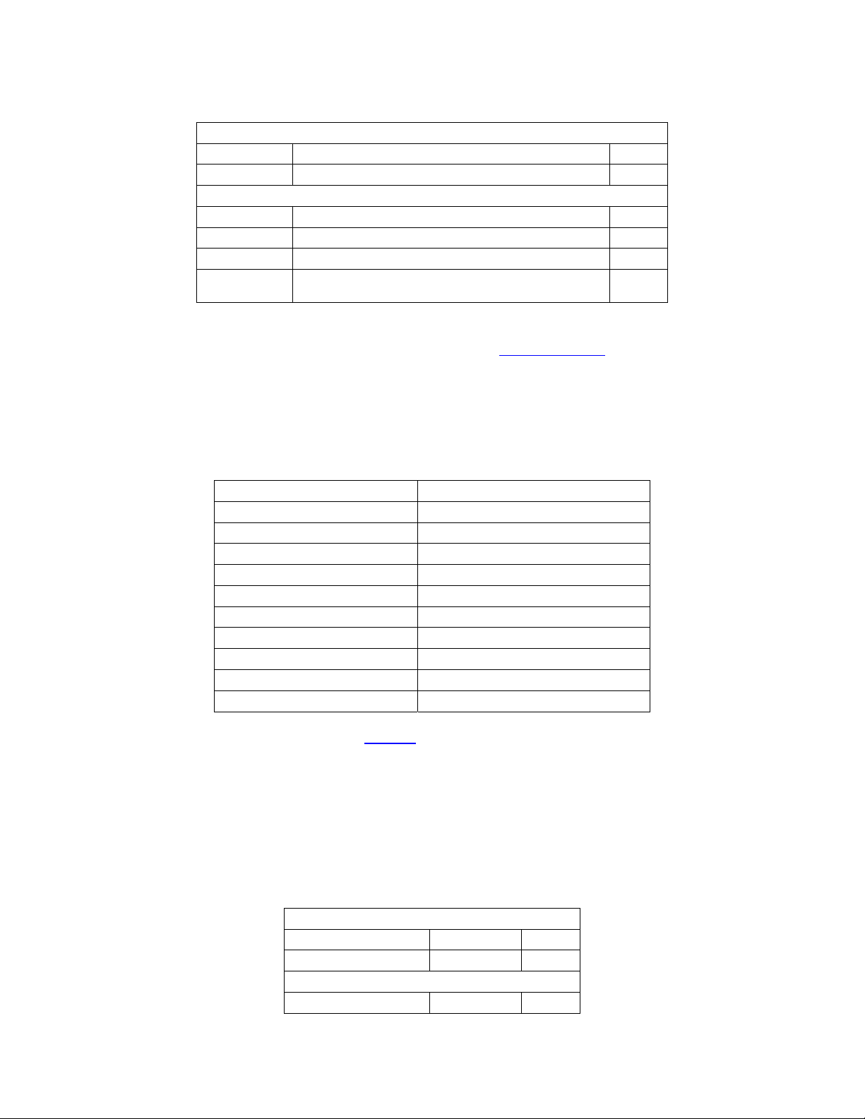
6.6.1 MC-4 Get Unit Configuration
The HOST initiates by sending the GET_UNIT_CONFIG command packet:
SOP DLL DC CMD AppDC EOP
F1 03 38 00 F2
If the command is received without error, the MC-4 responds with the UNIT_CONFIG response packet:
SOP DLL DC CMD App DC DATA0 DATA1 DATA2
Product Id SW TYPE SW LVL
F1 1E 91 19 04 04 00
DATA3 DATA4 DATA5 DATA6 DATA7 DATA8 DATA9
PARAM
SW MJ
REV
SW MN
01 00 01 01 EF 03 23
REV
PTCL MJ
REV
PTCL MN
REV
COUNT
(LSB)
PARAM
COUNT
(MSB)
EFFECT
COUNT
DATA10 DATA11 DATA12 DATA13 DATA14 DATA15 DATA16 DATA17
Time
Stamp
30 31 2f 30 37 2f 32 37
0 1 / 0 7 / 2 7
Time
Stamp
Time
Stamp
Time
Stamp
Time
Stamp
Time
Stamp
Time
Stamp
Time
Stamp
DATA18 DATA19 DATA20 DATA21 DATA22 DATA23 DATA24 DATA25
Time
Stamp
20 31 37 3A 30 37 00 00
(sp) 1 7 : 0 7
Time
Stamp
Time
Stamp
Time
Stamp
Time
Stamp
Time
Stamp
Time
Stamp
Time
Stamp
DATA26 DATA27 DATA28 DATA29 EOP
Serial Number (LSB) Serial Number Serial Number Serial Number (MSB)
68 04 00 00 F2
From the response packet we can see that the MC-4 is configured as:
Product Id is Lexicon MC-4
Software type COMPLETE
Software level of RELEASED
Software Version 1.00
Protocol Version 1.01
with 1007 parameters
and 25 effects,
and the software image was built
“01/07/27 17:07”
and has an internal serial number of
1128 (0x00 00 04 68)
41
Page 42

Lexicon MC-4 Serial Communications Protocol
6.6.2 Send MC-4 IR Command Example
SOP DLL DC CMD AppDC DATA0 EOP
IR Key Code
F1 04 39 01 23 F2
This example shows how to transmit the IR command for “
MAIN_CD”. This example command will select
the CD input for the Main Zone. The bytes are transmitted from left to right and they are defined as:
Byte 0: Start of Packet (F1 hex)
Byte 1: Data Link Layer (DLL) Data Count (DC); for an IR command this would be 4 bytes to follow
Byte 2: The Application Layer Command, in this case it is 39 hex indicating this is an IR command
packet.
Byte 3: The Application Layer Data Count (DC); for this packet it is 1 data byte to follow.
Byte 4: The Application Command Data: This IR Command Packet is transmitting Key Code
“
MAIN_CD”(23 hex). To transmit other IR Key Codes the user would replace this byte with other
IR key codes as found in
Appendix C: MC-4 IR Codes.
Byte 5: End of Packet (F2 hex)
42
Page 43

Lexicon MC-4 Serial Communications Protocol
MC-4 V1.00 Parameter Id List
The following table is for V1.00 reference only. These Parameter Id Values will change with S/W and
Protocol version changes. The MC-4 can always be queried for the correct Parameter Id numbers and
Parameter Definition Packets.
ParamId
(dec)
0 0x0000
1 0x0001 PARAM.INPUTS
2 0x0002 PARAM.INPUTS.OFF
3 0x0003 PARAM.INPUTS.OFF.INPNAME
4 0x0004 PARAM.INPUTS.OFF.DIGIN
5 0x0005 PARAM.INPUTS.OFF.ANLGIN
6 0x0006 PARAM.INPUTS.OFF.ANLGTRIM
7 0x0007 PARAM.INPUTS.OFF.TRIMMODE
8 0x0008 PARAM.INPUTS.OFF.VIDEOIN
9 0x0009 PARAM.INPUTS.OFF.CH2EFFCT
10 0x000A PARAM.INPUTS.OFF.DDEFFCT
11 0x000B PARAM.INPUTS.OFF.DTSEFFCT
12 0x000C PARAM.INPUTS.OFF.MSRCMODE
13 0x000D PARAM.INPUTS.OFF.ANLGBYPASS
14 0x000E PARAM.INPUTS.OFF.TRIGGER1
15 0x000F PARAM.INPUTS.OFF.COMPONENTIN
16 0x0010 PARAM.INPUTS.OFF.SVID_16_9
17 0x0011 PARAM.INPUTS.OFF.SVIDOSD_4_3
18 0x0012 PARAM.INPUTS.OFF.COMPNTOSD
19 0x0013 PARAM.INPUTS.OFF._51_AD_EFFECT
20 0x0014 PARAM.INPUTS.DVD1
21 0x0015 PARAM.INPUTS.DVD1.INPNAME
22 0x0016 PARAM.INPUTS.DVD1.DIGIN
23 0x0017 PARAM.INPUTS.DVD1.ANLGIN
24 0x0018 PARAM.INPUTS.DVD1.ANLGTRIM
25 0x0019 PARAM.INPUTS.DVD1.TRIMMODE
26 0x001A PARAM.INPUTS.DVD1.VIDEOIN
27 0x001B PARAM.INPUTS.DVD1.CH2EFFCT
28 0x001C PARAM.INPUTS.DVD1.DDEFFCT
29 0x001D PARAM.INPUTS.DVD1.DTSEFFCT
30 0x001E PARAM.INPUTS.DVD1.MSRCMODE
31 0x001F PARAM.INPUTS.DVD1.ANLGBYPASS
32 0x0020 PARAM.INPUTS.DVD1.TRIGGER1
33 0x0021 PARAM.INPUTS.DVD1.COMPONENTIN
34 0x0022 PARAM.INPUTS.DVD1.SVID_16_9
35 0x0023 PARAM.INPUTS.DVD1.SVIDOSD_4_3
36 0x0024 PARAM.INPUTS.DVD1.COMPNTOSD
37 0x0025 PARAM.INPUTS.DVD1._51_AD_EFFECT
38 0x0026 PARAM.INPUTS.DVD2
ParamId
(hex)
Parameter Name
43
Page 44

Lexicon MC-4 Serial Communications Protocol
39 0x0027 PARAM.INPUTS.DVD2.INPNAME
40 0x0028 PARAM.INPUTS.DVD2.DIGIN
41 0x0029 PARAM.INPUTS.DVD2.ANLGIN
42 0x002A PARAM.INPUTS.DVD2.ANLGTRIM
43 0x002B PARAM.INPUTS.DVD2.TRIMMODE
44 0x002C PARAM.INPUTS.DVD2.VIDEOIN
45 0x002D PARAM.INPUTS.DVD2.CH2EFFCT
46 0x002E PARAM.INPUTS.DVD2.DDEFFCT
47 0x002F PARAM.INPUTS.DVD2.DTSEFFCT
48 0x0030 PARAM.INPUTS.DVD2.MSRCMODE
49 0x0031 PARAM.INPUTS.DVD2.ANLGBYPASS
50 0x0032 PARAM.INPUTS.DVD2.TRIGGER1
51 0x0033 PARAM.INPUTS.DVD2.COMPONENTIN
52 0x0034 PARAM.INPUTS.DVD2.SVID_16_9
53 0x0035 PARAM.INPUTS.DVD2.SVIDOSD_4_3
54 0x0036 PARAM.INPUTS.DVD2.COMPNTOSD
55 0x0037 PARAM.INPUTS.DVD2._51_AD_EFFECT
56 0x0038 PARAM.INPUTS.CD
57 0x0039 PARAM.INPUTS.CD.INPNAME
58 0x003A PARAM.INPUTS.CD.DIGIN
59 0x003B PARAM.INPUTS.CD.ANLGIN
60 0x003C PARAM.INPUTS.CD.ANLGTRIM
61 0x003D PARAM.INPUTS.CD.TRIMMODE
62 0x003E PARAM.INPUTS.CD.VIDEOIN
63 0x003F PARAM.INPUTS.CD.CH2EFFCT
64 0x0040 PARAM.INPUTS.CD.DDEFFCT
65 0x0041 PARAM.INPUTS.CD.DTSEFFCT
66 0x0042 PARAM.INPUTS.CD.MSRCMODE
67 0x0043 PARAM.INPUTS.CD.ANLGBYPASS
68 0x0044 PARAM.INPUTS.CD.TRIGGER1
69 0x0045 PARAM.INPUTS.CD.COMPONENTIN
70 0x0046 PARAM.INPUTS.CD.SVID_16_9
71 0x0047 PARAM.INPUTS.CD.SVIDOSD_4_3
72 0x0048 PARAM.INPUTS.CD.COMPNTOSD
73 0x0049 PARAM.INPUTS.CD._51_AD_EFFECT
74 0x004A PARAM.INPUTS.TUNER
75 0x004B PARAM.INPUTS.TUNER.INPNAME
76 0x004C PARAM.INPUTS.TUNER.DIGIN
77 0x004D PARAM.INPUTS.TUNER.ANLGIN
78 0x004E PARAM.INPUTS.TUNER.ANLGTRIM
79 0x004F PARAM.INPUTS.TUNER.TRIMMODE
80 0x0050 PARAM.INPUTS.TUNER.VIDEOIN
81 0x0051 PARAM.INPUTS.TUNER.CH2EFFCT
82 0x0052 PARAM.INPUTS.TUNER.DDEFFCT
83 0x0053 PARAM.INPUTS.TUNER.DTSEFFCT
84 0x0054 PARAM.INPUTS.TUNER.MSRCMODE
44
Page 45

Lexicon MC-4 Serial Communications Protocol
85 0x0055 PARAM.INPUTS.TUNER.ANLGBYPASS
86 0x0056 PARAM.INPUTS.TUNER.TRIGGER1
87 0x0057 PARAM.INPUTS.TUNER.COMPONENTIN
88 0x0058 PARAM.INPUTS.TUNER.SVID_16_9
89 0x0059 PARAM.INPUTS.TUNER.SVIDOSD_4_3
90 0x005A PARAM.INPUTS.TUNER.COMPNTOSD
91 0x005B PARAM.INPUTS.TUNER._51_AD_EFFECT
92 0x005C PARAM.INPUTS.TV
93 0x005D PARAM.INPUTS.TV.INPNAME
94 0x005E PARAM.INPUTS.TV.DIGIN
95 0x005F PARAM.INPUTS.TV.ANLGIN
96 0x0060 PARAM.INPUTS.TV.ANLGTRIM
97 0x0061 PARAM.INPUTS.TV.TRIMMODE
98 0x0062 PARAM.INPUTS.TV.VIDEOIN
99 0x0063 PARAM.INPUTS.TV.CH2EFFCT
100 0x0064 PARAM.INPUTS.TV.DDEFFCT
101 0x0065 PARAM.INPUTS.TV.DTSEFFCT
102 0x0066 PARAM.INPUTS.TV.MSRCMODE
103 0x0067 PARAM.INPUTS.TV.ANLGBYPASS
104 0x0068 PARAM.INPUTS.TV.TRIGGER1
105 0x0069 PARAM.INPUTS.TV.COMPONENTIN
106 0x006A PARAM.INPUTS.TV.SVID_16_9
107 0x006B PARAM.INPUTS.TV.SVIDOSD_4_3
108 0x006C PARAM.INPUTS.TV.COMPNTOSD
109 0x006D PARAM.INPUTS.TV._51_AD_EFFECT
110 0x006E PARAM.INPUTS.VCR
111 0x006F PARAM.INPUTS.VCR.INPNAME
112 0x0070 PARAM.INPUTS.VCR.DIGIN
113 0x0071 PARAM.INPUTS.VCR.ANLGIN
114 0x0072 PARAM.INPUTS.VCR.ANLGTRIM
115 0x0073 PARAM.INPUTS.VCR.TRIMMODE
116 0x0074 PARAM.INPUTS.VCR.CH2EFFCT
117 0x0075 PARAM.INPUTS.VCR.VIDEOIN
118 0x0076 PARAM.INPUTS.VCR.DDEFFCT
119 0x0077 PARAM.INPUTS.VCR.DTSEFFCT
120 0x0078 PARAM.INPUTS.VCR.MSRCMODE
121 0x0079 PARAM.INPUTS.VCR.ANLGBYPASS
122 0x007A PARAM.INPUTS.VCR.TRIGGER1
123 0x007B PARAM.INPUTS.VCR.COMPONENTIN
124 0x007C PARAM.INPUTS.VCR.SVID_16_9
125 0x007D PARAM.INPUTS.VCR.SVIDOSD_4_3
126 0x007E PARAM.INPUTS.VCR.COMPNTOSD
127 0x007F PARAM.INPUTS.VCR._51_AD_EFFECT
128 0x0080 PARAM.INPUTS.SAT
129 0x0081 PARAM.INPUTS.SAT.INPNAME
130 0x0082 PARAM.INPUTS.SAT.DIGIN
45
Page 46

Lexicon MC-4 Serial Communications Protocol
131 0x0083 PARAM.INPUTS.SAT.ANLGIN
132 0x0084 PARAM.INPUTS.SAT.ANLGTRIM
133 0x0085 PARAM.INPUTS.SAT.TRIMMODE
134 0x0086 PARAM.INPUTS.SAT.VIDEOIN
135 0x0087 PARAM.INPUTS.SAT.CH2EFFCT
136 0x0088 PARAM.INPUTS.SAT.DDEFFCT
137 0x0089 PARAM.INPUTS.SAT.DTSEFFCT
138 0x008A PARAM.INPUTS.SAT.MSRCMODE
139 0x008B PARAM.INPUTS.SAT.ANLGBYPASS
140 0x008C PARAM.INPUTS.SAT.TRIGGER1
141 0x008D PARAM.INPUTS.SAT.COMPONENTIN
142 0x008E PARAM.INPUTS.SAT.SVID_16_9
143 0x008F PARAM.INPUTS.SAT.SVIDOSD_4_3
144 0x0090 PARAM.INPUTS.SAT.COMPNTOSD
145 0x0091 PARAM.INPUTS.SAT._51_AD_EFFECT
146 0x0092 PARAM.INPUTS.AUX
147 0x0093 PARAM.INPUTS.AUX.INPNAME
148 0x0094 PARAM.INPUTS.AUX.DIGIN
149 0x0095 PARAM.INPUTS.AUX.ANLGIN
150 0x0096 PARAM.INPUTS.AUX.ANLGTRIM
151 0x0097 PARAM.INPUTS.AUX.TRIMMODE
152 0x0098 PARAM.INPUTS.AUX.VIDEOIN
153 0x0099 PARAM.INPUTS.AUX.CH2EFFCT
154 0x009A PARAM.INPUTS.AUX.DDEFFCT
155 0x009B PARAM.INPUTS.AUX.DTSEFFCT
156 0x009C PARAM.INPUTS.AUX.MSRCMODE
157 0x009D PARAM.INPUTS.AUX.ANLGBYPASS
158 0x009E PARAM.INPUTS.AUX.TRIGGER1
159 0x009F PARAM.INPUTS.AUX.COMPONENTIN
160 0x00A0 PARAM.INPUTS.AUX.SVID_16_9
161 0x00A1 PARAM.INPUTS.AUX.SVIDOSD_4_3
162 0x00A2 PARAM.INPUTS.AUX.COMPNTOSD
163 0x00A3 PARAM.INPUTS.AUX._51_AD_EFFECT
164 0x00A4 PARAM.INPUTS.ANLGCONFIG
165 0x00A5 PARAM.INPUTS.LEVELS
166 0x00A6 PARAM.INPUTS.LEVELS.INLEFT
167 0x00A7 PARAM.INPUTS.LEVELS.INRIGHT
168 0x00A8 PARAM.INPUTS.LEVELS.INCENTER
169 0x00A9 PARAM.INPUTS.LEVELS.INLFE
170 0x00AA PARAM.INPUTS.LEVELS.SIDELEFT
171 0x00AB PARAM.INPUTS.LEVELS.SIDERIGHT
172 0x00AC PARAM.INPUTS.LEVELS.REARLEFT
173 0x00AD PARAM.INPUTS.LEVELS.REARRIGHT
174 0x00AE PARAM.INPUTS.LEVELS.PEAK
175 0x00AF PARAM.INPUTS.AUTOTRIM
176 0x00B0 PARAM.MAIN
46
Page 47

Lexicon MC-4 Serial Communications Protocol
177 0x00B1 PARAM.MAIN.OUTPUTS
178 0x00B2 PARAM.MAIN.OUTPUTS.FRONT
179 0x00B3 PARAM.MAIN.OUTPUTS.FRONT.HP_XOVER
180 0x00B4 PARAM.MAIN.OUTPUTS.FRONT.LEFT
181 0x00B5 PARAM.MAIN.OUTPUTS.FRONT.LEFT.DISTANCE
182 0x00B6 PARAM.MAIN.OUTPUTS.FRONT.LEFT.OUTLEVEL
183 0x00B7 PARAM.MAIN.OUTPUTS.FRONT.RIGHT
184 0x00B8 PARAM.MAIN.OUTPUTS.FRONT.RIGHT.DISTANCE
185 0x00B9 PARAM.MAIN.OUTPUTS.FRONT.RIGHT.OUTLEVEL
186 0x00BA PARAM.MAIN.OUTPUTS.CENTER
187 0x00BB PARAM.MAIN.OUTPUTS.CENTER.HP_XOVER
188 0x00BC PARAM.MAIN.OUTPUTS.CENTER.DISTANCE
189 0x00BD PARAM.MAIN.OUTPUTS.CENTER.OUTLEVEL
190 0x00BE PARAM.MAIN.OUTPUTS.SIDE
191 0x00BF PARAM.MAIN.OUTPUTS.SIDE.HP_XOVER
192 0x00C0 PARAM.MAIN.OUTPUTS.SIDE.LEFT
193 0x00C1 PARAM.MAIN.OUTPUTS.SIDE.LEFT.DISTANCE
194 0x00C2 PARAM.MAIN.OUTPUTS.SIDE.LEFT.OUTLEVEL
195 0x00C3 PARAM.MAIN.OUTPUTS.SIDE.RIGHT
196 0x00C4 PARAM.MAIN.OUTPUTS.SIDE.RIGHT.DISTANCE
197 0x00C5 PARAM.MAIN.OUTPUTS.SIDE.RIGHT.OUTLEVEL
198 0x00C6 PARAM.MAIN.OUTPUTS.REAR
199 0x00C7 PARAM.MAIN.OUTPUTS.REAR.HP_XOVER
200 0x00C8 PARAM.MAIN.OUTPUTS.REAR.LEFT
201 0x00C9 PARAM.MAIN.OUTPUTS.REAR.LEFT.DISTANCE
202 0x00CA PARAM.MAIN.OUTPUTS.REAR.LEFT.OUTLEVEL
203 0x00CB PARAM.MAIN.OUTPUTS.REAR.RIGHT
204 0x00CC PARAM.MAIN.OUTPUTS.REAR.RIGHT.DISTANCE
205 0x00CD PARAM.MAIN.OUTPUTS.REAR.RIGHT.OUTLEVEL
206 0x00CE PARAM.MAIN.OUTPUTS.SUB
207 0x00CF PARAM.MAIN.OUTPUTS.SUB.LP_XOVER
208 0x00D0 PARAM.MAIN.OUTPUTS.SUB.LEFT
209 0x00D1 PARAM.MAIN.OUTPUTS.SUB.LEFT.DISTANCE
210 0x00D2 PARAM.MAIN.OUTPUTS.SUB.LEFT.OUTLEVEL
211 0x00D3 PARAM.MAIN.OUTPUTS.SUB.RIGHT
212 0x00D4 PARAM.MAIN.OUTPUTS.SUB.RIGHT.DISTANCE
213 0x00D5 PARAM.MAIN.OUTPUTS.SUB.RIGHT.OUTLEVEL
214 0x00D6 PARAM.MAIN.OUTPUTS.SUB.CONFIG
215 0x00D7 PARAM.MAIN.OUTPUTS.SUB.LIMITEN
216 0x00D8 PARAM.MAIN.OUTPUTS.SUB.LIMITADJ
217 0x00D9 PARAM.MAIN.OUTPUTS.DISTUNITS
218 0x00DA PARAM.MAIN.OUTPUTS.SUBNOISE
219 0x00DB PARAM.MAIN.OUTPUTS.THX_ULTRA2_SUB
220 0x00DC PARAM.MAIN.OUTPUTS.THX_BGC
221 0x00DD PARAM.MAIN.OUTPUTS.THX_ASA
222 0x00DE PARAM.MAIN.DATA_STREAM
47
Page 48

Lexicon MC-4 Serial Communications Protocol
223 0x00DF PARAM.MAIN.DATA_STREAM.SAMPLE_RATE
224 0x00E0 PARAM.MAIN.DATA_STREAM.DATA_TYPE
225 0x00E1 PARAM.MAIN.DATA_STREAM.CHANNELS
226 0x00E2 PARAM.MAIN.INPUT
227 0x00E3 PARAM.MAIN.EFFECT
228 0x00E4 PARAM.MAIN.VOLUME
229 0x00E5 PARAM.MAIN.BALANCE
230 0x00E6 PARAM.MAIN.FADER
231 0x00E7 PARAM.MAIN.PWRONVOL
232 0x00E8 PARAM.MAIN.MUTEBY
233 0x00E9 PARAM.MAIN.BASS
234 0x00EA PARAM.MAIN.TREBLE
235 0x00EB PARAM.MAIN.TILT
236 0x00EC PARAM.MAIN.MUTE
237 0x00ED PARAM.MAIN.MODE
238 0x00EE PARAM.MAIN.LOUDNESS
239 0x00EF PARAM.MAIN.DOLBYDATA
240 0x00F0 PARAM.MAIN.DOLBYDATA.DD_CHAN
241 0x00F1 PARAM.MAIN.DOLBYDATA.ENCODING
242 0x00F2 PARAM.MAIN.DOLBYDATA.REF_OFFSET
243 0x00F3 PARAM.MAIN.DOLBYDATA.DDBITRATE
244 0x00F4 PARAM.MAIN.DOLBYDATA.EXDETECT
245 0x00F5 PARAM.MAIN.DOLBYDATA.ROOMTYPE
246 0x00F6 PARAM.MAIN.DOLBYDATA.CLEV
247 0x00F7 PARAM.MAIN.DOLBYDATA.SLEV
248 0x00F8 PARAM.MAIN.DTSDATA
249 0x00F9 PARAM.MAIN.DTSDATA.DTS_CHAN
250 0x00FA PARAM.MAIN.DTSDATA.ES_FLAG
251 0x00FB PARAM.MAIN.DTSDATA.DTSBITRATE
252 0x00FC PARAM.MAIN.DTSDATA.WORDLEN
253 0x00FD PARAM.MAIN.DTSDATA.SFREQ
254 0x00FE PARAM.MAIN.DTSDATA._9624FLAG
255 0x00FF PARAM.EFFECTS
256 0x0100 PARAM.EFFECTS.INT_NOISE
257 0x0101 PARAM.EFFECTS.INT_NOISE.NAME
258 0x0102 PARAM.EFFECTS.INT_NOISE.OUTPUTLEVELS
259 0x0103 PARAM.EFFECTS.INT_NOISE.OUTPUTLEVELS.CNTROUTLEVEL
260 0x0104 PARAM.EFFECTS.INT_NOISE.OUTPUTLEVELS.SIDEOUTLEVEL
261 0x0105 PARAM.EFFECTS.INT_NOISE.OUTPUTLEVELS.REAROUTLEVEL
262 0x0106 PARAM.EFFECTS.INT_NOISE.OUTPUTLEVELS.SUBOUTLEVEL
263 0x0107 PARAM.EFFECTS.INT_NOISE.TRIGGER1
264 0x0108 PARAM.EFFECTS.INT_NOISE.FRONTOUTLEVEL
265 0x0109 PARAM.EFFECTS.LOGIC7
266 0x010A PARAM.EFFECTS.LOGIC7.NAME
267 0x010B PARAM.EFFECTS.LOGIC7.OUTPUTLEVELS
268 0x010C PARAM.EFFECTS.LOGIC7.OUTPUTLEVELS.CNTROUTLEVEL
48
Page 49

Lexicon MC-4 Serial Communications Protocol
269 0x010D PARAM.EFFECTS.LOGIC7.OUTPUTLEVELS.SIDEOUTLEVEL
270 0x010E PARAM.EFFECTS.LOGIC7.OUTPUTLEVELS.REAROUTLEVEL
271 0x010F PARAM.EFFECTS.LOGIC7.OUTPUTLEVELS.SUBOUTLEVEL
272 0x0110 PARAM.EFFECTS.LOGIC7.AUTOAZIMUTH
273 0x0111 PARAM.EFFECTS.LOGIC7.VOCALENH
274 0x0112 PARAM.EFFECTS.LOGIC7.FRONTSTEER
275 0x0113 PARAM.EFFECTS.LOGIC7.REEQ
276 0x0114 PARAM.EFFECTS.LOGIC7.SOUNDSTAGE
277 0x0115 PARAM.EFFECTS.LOGIC7.FIVESPKRENH
278 0x0116 PARAM.EFFECTS.LOGIC7.BASSENH
279 0x0117 PARAM.EFFECTS.LOGIC7.SURRROLLOFF
280 0x0118 PARAM.EFFECTS.LOGIC7.REARDLYOFF
281 0x0119 PARAM.EFFECTS.LOGIC7.CENTERONOFF
282 0x011A PARAM.EFFECTS.LOGIC7.SEVENCHANNEL
283 0x011B PARAM.EFFECTS.LOGIC7.MONODETECT_ON
284 0x011C PARAM.EFFECTS.LOGIC7.SURRONOFF
285 0x011D PARAM.EFFECTS.LOGIC7.TRIGGER1
286 0x011E PARAM.EFFECTS.LOGIC7.HIFRONT_REARROLLOFF
287 0x011F PARAM.EFFECTS.LOGIC7.AUTOBALON
288 0x0120 PARAM.EFFECTS.TV_LOGIC
289 0x0121 PARAM.EFFECTS.TV_LOGIC.NAME
290 0x0122 PARAM.EFFECTS.TV_LOGIC.OUTPUTLEVELS
291 0x0123 PARAM.EFFECTS.TV_LOGIC.OUTPUTLEVELS.CNTROUTLEVEL
292 0x0124 PARAM.EFFECTS.TV_LOGIC.OUTPUTLEVELS.SIDEOUTLEVEL
293 0x0125 PARAM.EFFECTS.TV_LOGIC.OUTPUTLEVELS.REAROUTLEVEL
294 0x0126 PARAM.EFFECTS.TV_LOGIC.OUTPUTLEVELS.SUBOUTLEVEL
295 0x0127 PARAM.EFFECTS.TV_LOGIC.AUTOAZIMUTH
296 0x0128 PARAM.EFFECTS.TV_LOGIC.VOCALENH
297 0x0129 PARAM.EFFECTS.TV_LOGIC.FRONTSTEER
298 0x012A PARAM.EFFECTS.TV_LOGIC.REEQ
299 0x012B PARAM.EFFECTS.TV_LOGIC.SOUNDSTAGE
300 0x012C PARAM.EFFECTS.TV_LOGIC.FIVESPKRENH
301 0x012D PARAM.EFFECTS.TV_LOGIC.BASSENH
302 0x012E PARAM.EFFECTS.TV_LOGIC.SURRROLLOFF
303 0x012F PARAM.EFFECTS.TV_LOGIC.REARDLYOFF
304 0x0130 PARAM.EFFECTS.TV_LOGIC.CENTERONOFF
305 0x0131 PARAM.EFFECTS.TV_LOGIC.SEVENCHANNEL
306 0x0132 PARAM.EFFECTS.TV_LOGIC.MONODETECT_ON
307 0x0133 PARAM.EFFECTS.TV_LOGIC.SURRONOFF
308 0x0134 PARAM.EFFECTS.TV_LOGIC.TRIGGER1
309 0x0135 PARAM.EFFECTS.TV_LOGIC.HIFRONT_REARROLLOFF
310 0x0136 PARAM.EFFECTS.TV_LOGIC.AUTOBALON
311 0x0137 PARAM.EFFECTS.MUSIC_LOGIC
312 0x0138 PARAM.EFFECTS.MUSIC_LOGIC.NAME
313 0x0139 PARAM.EFFECTS.MUSIC_LOGIC.OUTPUTLEVELS
314 0x013A PARAM.EFFECTS.MUSIC_LOGIC.OUTPUTLEVELS.CNTROUTLEVEL
49
Page 50

Lexicon MC-4 Serial Communications Protocol
315 0x013B PARAM.EFFECTS.MUSIC_LOGIC.OUTPUTLEVELS.SIDEOUTLEVEL
316 0x013C PARAM.EFFECTS.MUSIC_LOGIC.OUTPUTLEVELS.REAROUTLEVEL
317 0x013D PARAM.EFFECTS.MUSIC_LOGIC.OUTPUTLEVELS.SUBOUTLEVEL
318 0x013E PARAM.EFFECTS.MUSIC_LOGIC.AUTOAZIMUTH
319 0x013F PARAM.EFFECTS.MUSIC_LOGIC.VOCALENH
320 0x0140 PARAM.EFFECTS.MUSIC_LOGIC.FRONTSTEER
321 0x0141 PARAM.EFFECTS.MUSIC_LOGIC.REEQ
322 0x0142 PARAM.EFFECTS.MUSIC_LOGIC.SOUNDSTAGE
323 0x0143 PARAM.EFFECTS.MUSIC_LOGIC.FIVESPKRENH
324 0x0144 PARAM.EFFECTS.MUSIC_LOGIC.BASSENH
325 0x0145 PARAM.EFFECTS.MUSIC_LOGIC.SURRROLLOFF
326 0x0146 PARAM.EFFECTS.MUSIC_LOGIC.REARDLYOFF
327 0x0147 PARAM.EFFECTS.MUSIC_LOGIC.CENTERONOFF
328 0x0148 PARAM.EFFECTS.MUSIC_LOGIC.SEVENCHANNEL
329 0x0149 PARAM.EFFECTS.MUSIC_LOGIC.MONODETECT_ON
330 0x014A PARAM.EFFECTS.MUSIC_LOGIC.SURRONOFF
331 0x014B PARAM.EFFECTS.MUSIC_LOGIC.TRIGGER1
332 0x014C PARAM.EFFECTS.MUSIC_LOGIC.HIFRONT_REARROLLOFF
333 0x014D PARAM.EFFECTS.MUSIC_LOGIC.AUTOBALON
334 0x014E PARAM.EFFECTS.THX_CINEMA
335 0x014F PARAM.EFFECTS.THX_CINEMA.NAME
336 0x0150 PARAM.EFFECTS.THX_CINEMA.OUTPUTLEVELS
337 0x0151 PARAM.EFFECTS.THX_CINEMA.OUTPUTLEVELS.CNTROUTLEVEL
338 0x0152 PARAM.EFFECTS.THX_CINEMA.OUTPUTLEVELS.SIDEOUTLEVEL
339 0x0153 PARAM.EFFECTS.THX_CINEMA.OUTPUTLEVELS.REAROUTLEVEL
340 0x0154 PARAM.EFFECTS.THX_CINEMA.OUTPUTLEVELS.SUBOUTLEVEL
341 0x0155 PARAM.EFFECTS.THX_CINEMA.TWO_CH_MUX
342 0x0156 PARAM.EFFECTS.THX_CINEMA.TWOCHCNTRMIX
343 0x0157 PARAM.EFFECTS.THX_CINEMA.CENTERDELAY
344 0x0158 PARAM.EFFECTS.THX_CINEMA.MONOREARON
345 0x0159 PARAM.EFFECTS.THX_CINEMA.DECORRELATE
346 0x015A PARAM.EFFECTS.THX_CINEMA.VOCALENH
347 0x015B PARAM.EFFECTS.THX_CINEMA.REEQ
348 0x015C PARAM.EFFECTS.THX_CINEMA.SURDLY10_25
349 0x015D PARAM.EFFECTS.THX_CINEMA.TIMBRE
350 0x015E PARAM.EFFECTS.THX_CINEMA.THXMODEON
351 0x015F PARAM.EFFECTS.THX_CINEMA.TRIGGER1
352 0x0160 PARAM.EFFECTS.THX_CINEMA.REARTIMBRE
353 0x0161 PARAM.EFFECTS.PROLOGIC
354 0x0162 PARAM.EFFECTS.PROLOGIC.NAME
355 0x0163 PARAM.EFFECTS.PROLOGIC.OUTPUTLEVELS
356 0x0164 PARAM.EFFECTS.PROLOGIC.OUTPUTLEVELS.CNTROUTLEVEL
357 0x0165 PARAM.EFFECTS.PROLOGIC.OUTPUTLEVELS.SIDEOUTLEVEL
358 0x0166 PARAM.EFFECTS.PROLOGIC.OUTPUTLEVELS.REAROUTLEVEL
359 0x0167 PARAM.EFFECTS.PROLOGIC.OUTPUTLEVELS.SUBOUTLEVEL
360 0x0168 PARAM.EFFECTS.PROLOGIC.TWO_CH_MUX
50
Page 51

Lexicon MC-4 Serial Communications Protocol
361 0x0169 PARAM.EFFECTS.PROLOGIC.TWOCHCNTRMIX
362 0x016A PARAM.EFFECTS.PROLOGIC.CENTERDELAY
363 0x016B PARAM.EFFECTS.PROLOGIC.MONOREARON
364 0x016C PARAM.EFFECTS.PROLOGIC.DECORRELATE
365 0x016D PARAM.EFFECTS.PROLOGIC.VOCALENH
366 0x016E PARAM.EFFECTS.PROLOGIC.REEQ
367 0x016F PARAM.EFFECTS.PROLOGIC.SURDLY10_25
368 0x0170 PARAM.EFFECTS.PROLOGIC.TRIGGER1
369 0x0171 PARAM.EFFECTS.PROLOGIC2
370 0x0172 PARAM.EFFECTS.PROLOGIC2.NAME
371 0x0173 PARAM.EFFECTS.PROLOGIC2.OUTPUTLEVELS
372 0x0174 PARAM.EFFECTS.PROLOGIC2.OUTPUTLEVELS.CNTROUTLEVEL
373 0x0175 PARAM.EFFECTS.PROLOGIC2.OUTPUTLEVELS.SIDEOUTLEVEL
374 0x0176 PARAM.EFFECTS.PROLOGIC2.OUTPUTLEVELS.REAROUTLEVEL
375 0x0177 PARAM.EFFECTS.PROLOGIC2.OUTPUTLEVELS.SUBOUTLEVEL
376 0x0178 PARAM.EFFECTS.PROLOGIC2.SURDLY10_25
377 0x0179 PARAM.EFFECTS.PROLOGIC2.TWO_CH_MUX
378 0x017A PARAM.EFFECTS.PROLOGIC2.TWOCHCNTRMIX
379 0x017B PARAM.EFFECTS.PROLOGIC2.CENTERDELAY
380 0x017C PARAM.EFFECTS.PROLOGIC2.MONOREARON
381 0x017D PARAM.EFFECTS.PROLOGIC2.DECORRELATE
382 0x017E PARAM.EFFECTS.PROLOGIC2.VOCALENH
383 0x017F PARAM.EFFECTS.PROLOGIC2.REEQ
384 0x0180 PARAM.EFFECTS.PROLOGIC2.TRIGGER1
385 0x0181 PARAM.EFFECTS.PL2MUSIC
386 0x0182 PARAM.EFFECTS.PL2MUSIC.NAME
387 0x0183 PARAM.EFFECTS.PL2MUSIC.OUTPUTLEVELS
388 0x0184 PARAM.EFFECTS.PL2MUSIC.OUTPUTLEVELS.CNTROUTLEVEL
389 0x0185 PARAM.EFFECTS.PL2MUSIC.OUTPUTLEVELS.SIDEOUTLEVEL
390 0x0186 PARAM.EFFECTS.PL2MUSIC.OUTPUTLEVELS.REAROUTLEVEL
391 0x0187 PARAM.EFFECTS.PL2MUSIC.OUTPUTLEVELS.SUBOUTLEVEL
392 0x0188 PARAM.EFFECTS.PL2MUSIC.SURROUNDDELAY
393 0x0189 PARAM.EFFECTS.PL2MUSIC.TWO_CH_MUX
394 0x018A PARAM.EFFECTS.PL2MUSIC.TWOCHCNTRMIX
395 0x018B PARAM.EFFECTS.PL2MUSIC.CENTERDELAY
396 0x018C PARAM.EFFECTS.PL2MUSIC.MONOREARON
397 0x018D PARAM.EFFECTS.PL2MUSIC.DECORRELATE
398 0x018E PARAM.EFFECTS.PL2MUSIC.VOCALENH
399 0x018F PARAM.EFFECTS.PL2MUSIC.REEQ
400 0x0190 PARAM.EFFECTS.PL2MUSIC.PL2PAN
401 0x0191 PARAM.EFFECTS.PL2MUSIC.CNTRWIDTH
402 0x0192 PARAM.EFFECTS.PL2MUSIC.DIMENSION
403 0x0193 PARAM.EFFECTS.PL2MUSIC.TRIGGER1
404 0x0194 PARAM.EFFECTS.PARTY
405 0x0195 PARAM.EFFECTS.PARTY.NAME
406 0x0196 PARAM.EFFECTS.PARTY.OUTPUTLEVELS
51
Page 52

Lexicon MC-4 Serial Communications Protocol
407 0x0197 PARAM.EFFECTS.PARTY.OUTPUTLEVELS.CNTROUTLEVEL
408 0x0198 PARAM.EFFECTS.PARTY.OUTPUTLEVELS.SIDEOUTLEVEL
409 0x0199 PARAM.EFFECTS.PARTY.OUTPUTLEVELS.REAROUTLEVEL
410 0x019A PARAM.EFFECTS.PARTY.OUTPUTLEVELS.SUBOUTLEVEL
411 0x019B PARAM.EFFECTS.PARTY.AUTOAZIMUTH
412 0x019C PARAM.EFFECTS.PARTY.VOCALENH
413 0x019D PARAM.EFFECTS.PARTY.REEQ
414 0x019E PARAM.EFFECTS.PARTY.MONOCNTR
415 0x019F PARAM.EFFECTS.PARTY.TRIGGER1
416 0x01A0 PARAM.EFFECTS.STEREO
417 0x01A1 PARAM.EFFECTS.STEREO.NAME
418 0x01A2 PARAM.EFFECTS.STEREO.OUTPUTLEVELS
419 0x01A3 PARAM.EFFECTS.STEREO.OUTPUTLEVELS.CNTROUTLEVEL
420 0x01A4 PARAM.EFFECTS.STEREO.OUTPUTLEVELS.SIDEOUTLEVEL
421 0x01A5 PARAM.EFFECTS.STEREO.OUTPUTLEVELS.REAROUTLEVEL
422 0x01A6 PARAM.EFFECTS.STEREO.OUTPUTLEVELS.SUBOUTLEVEL
423 0x01A7 PARAM.EFFECTS.STEREO.AUTOAZIMUTH
424 0x01A8 PARAM.EFFECTS.STEREO.VOCALENH
425 0x01A9 PARAM.EFFECTS.STEREO.REEQ
426 0x01AA PARAM.EFFECTS.STEREO.MONOCNTR
427 0x01AB PARAM.EFFECTS.STEREO.TRIGGER1
428 0x01AC PARAM.EFFECTS.MONO_LOGIC
429 0x01AD PARAM.EFFECTS.MONO_LOGIC.NAME
430 0x01AE PARAM.EFFECTS.MONO_LOGIC.MONOENH
431 0x01AF PARAM.EFFECTS.MONO_LOGIC.MAINLEVEL
432 0x01B0 PARAM.EFFECTS.MONO_LOGIC.ACADEMY
433 0x01B1 PARAM.EFFECTS.MONO_LOGIC.SURRROLLOFF
434 0x01B2 PARAM.EFFECTS.MONO_LOGIC.EFFECTLEVEL
435 0x01B3 PARAM.EFFECTS.MONO_LOGIC.OUTPUTLEVELS
436 0x01B4 PARAM.EFFECTS.MONO_LOGIC.OUTPUTLEVELS.CNTROUTLEVEL
437 0x01B5 PARAM.EFFECTS.MONO_LOGIC.OUTPUTLEVELS.SIDEOUTLEVEL
438 0x01B6 PARAM.EFFECTS.MONO_LOGIC.OUTPUTLEVELS.REAROUTLEVEL
439 0x01B7 PARAM.EFFECTS.MONO_LOGIC.OUTPUTLEVELS.SUBOUTLEVEL
440 0x01B8 PARAM.EFFECTS.MONO_LOGIC.VOCALENH
441 0x01B9 PARAM.EFFECTS.MONO_LOGIC.REEQ
442 0x01BA PARAM.EFFECTS.MONO_LOGIC.USEREVERB
443 0x01BB PARAM.EFFECTS.MONO_LOGIC.TRIGGER1
444 0x01BC PARAM.EFFECTS.MONO
445 0x01BD PARAM.EFFECTS.MONO.NAME
446 0x01BE PARAM.EFFECTS.MONO.OUTPUTLEVELS
447 0x01BF PARAM.EFFECTS.MONO.OUTPUTLEVELS.CNTROUTLEVEL
448 0x01C0 PARAM.EFFECTS.MONO.OUTPUTLEVELS.SIDEOUTLEVEL
449 0x01C1 PARAM.EFFECTS.MONO.OUTPUTLEVELS.REAROUTLEVEL
450 0x01C2 PARAM.EFFECTS.MONO.OUTPUTLEVELS.SUBOUTLEVEL
451 0x01C3 PARAM.EFFECTS.MONO.USEREVERB
452 0x01C4 PARAM.EFFECTS.MONO.FRONTOUTLEVEL
52
Page 53

Lexicon MC-4 Serial Communications Protocol
453 0x01C5 PARAM.EFFECTS.MONO.TRIGGER1
454 0x01C6 PARAM.EFFECTS.MONO_SURROUND
455 0x01C7 PARAM.EFFECTS.MONO_SURROUND.NAME
456 0x01C8 PARAM.EFFECTS.MONO_SURROUND.OUTPUTLEVELS
457 0x01C9 PARAM.EFFECTS.MONO_SURROUND.OUTPUTLEVELS.CNTROUTLEVEL
458 0x01CA PARAM.EFFECTS.MONO_SURROUND.OUTPUTLEVELS.SIDEOUTLEVEL
459 0x01CB PARAM.EFFECTS.MONO_SURROUND.OUTPUTLEVELS.REAROUTLEVEL
460 0x01CC PARAM.EFFECTS.MONO_SURROUND.OUTPUTLEVELS.SUBOUTLEVEL
461 0x01CD PARAM.EFFECTS.MONO_SURROUND.USEREVERB
462 0x01CE PARAM.EFFECTS.MONO_SURROUND.TRIGGER1
463 0x01CF PARAM.EFFECTS._51_LOGIC7
464 0x01D0 PARAM.EFFECTS._51_LOGIC7.NAME
465 0x01D1 PARAM.EFFECTS._51_LOGIC7.OUTPUTLEVELS
466 0x01D2 PARAM.EFFECTS._51_LOGIC7.OUTPUTLEVELS.CNTROUTLEVEL
467 0x01D3 PARAM.EFFECTS._51_LOGIC7.OUTPUTLEVELS.SIDEOUTLEVEL
468 0x01D4 PARAM.EFFECTS._51_LOGIC7.OUTPUTLEVELS.REAROUTLEVEL
469 0x01D5 PARAM.EFFECTS._51_LOGIC7.OUTPUTLEVELS.SUBOUTLEVEL
470 0x01D6 PARAM.EFFECTS._51_LOGIC7.VOCALENH
471 0x01D7 PARAM.EFFECTS._51_LOGIC7.FIVESPKRENH
472 0x01D8 PARAM.EFFECTS._51_LOGIC7.BASSENH
473 0x01D9 PARAM.EFFECTS._51_LOGIC7.REEQ
474 0x01DA PARAM.EFFECTS._51_LOGIC7.REARDLYOFF
475 0x01DB PARAM.EFFECTS._51_LOGIC7.COMPRESSION
476 0x01DC PARAM.EFFECTS._51_LOGIC7.LFEMIX
477 0x01DD PARAM.EFFECTS._51_LOGIC7.TWO_CH_MUX
478 0x01DE PARAM.EFFECTS._51_LOGIC7.TWOCHCNTRMIX
479 0x01DF PARAM.EFFECTS._51_LOGIC7.CENTERDELAY
480 0x01E0 PARAM.EFFECTS._51_LOGIC7.SOUNDSTAGE
481 0x01E1 PARAM.EFFECTS._51_LOGIC7.FRONTSTEER
482 0x01E2 PARAM.EFFECTS._51_LOGIC7.SURREX
483 0x01E3 PARAM.EFFECTS._51_LOGIC7.SEVENCHANNEL
484 0x01E4 PARAM.EFFECTS._51_LOGIC7.TRIGGER1
485 0x01E5 PARAM.EFFECTS._51_LOGIC7.MONOREARON
486 0x01E6 PARAM.EFFECTS._51_MUSIC
487 0x01E7 PARAM.EFFECTS._51_MUSIC.NAME
488 0x01E8 PARAM.EFFECTS._51_MUSIC.OUTPUTLEVELS
489 0x01E9 PARAM.EFFECTS._51_MUSIC.OUTPUTLEVELS.CNTROUTLEVEL
490 0x01EA PARAM.EFFECTS._51_MUSIC.OUTPUTLEVELS.SIDEOUTLEVEL
491 0x01EB PARAM.EFFECTS._51_MUSIC.OUTPUTLEVELS.REAROUTLEVEL
492 0x01EC PARAM.EFFECTS._51_MUSIC.OUTPUTLEVELS.SUBOUTLEVEL
493 0x01ED PARAM.EFFECTS._51_MUSIC.VOCALENH
494 0x01EE PARAM.EFFECTS._51_MUSIC.FIVESPKRENH
495 0x01EF PARAM.EFFECTS._51_MUSIC.BASSENH
496 0x01F0 PARAM.EFFECTS._51_MUSIC.REEQ
497 0x01F1 PARAM.EFFECTS._51_MUSIC.REARDLYOFF
498 0x01F2 PARAM.EFFECTS._51_MUSIC.COMPRESSION
53
Page 54

Lexicon MC-4 Serial Communications Protocol
499 0x01F3 PARAM.EFFECTS._51_MUSIC.LFEMIX
500 0x01F4 PARAM.EFFECTS._51_MUSIC.TWO_CH_MUX
501 0x01F5 PARAM.EFFECTS._51_MUSIC.TWOCHCNTRMIX
502 0x01F6 PARAM.EFFECTS._51_MUSIC.CENTERDELAY
503 0x01F7 PARAM.EFFECTS._51_MUSIC.SOUNDSTAGE
504 0x01F8 PARAM.EFFECTS._51_MUSIC.FRONTSTEER
505 0x01F9 PARAM.EFFECTS._51_MUSIC.SURREX
506 0x01FA PARAM.EFFECTS._51_MUSIC.SEVENCHANNEL
507 0x01FB PARAM.EFFECTS._51_MUSIC.TRIGGER1
508 0x01FC PARAM.EFFECTS._51_MUSIC.MONOREARON
509 0x01FD PARAM.EFFECTS._51_TV_LOGIC
510 0x01FE PARAM.EFFECTS._51_TV_LOGIC.NAME
511 0x01FF PARAM.EFFECTS._51_TV_LOGIC.OUTPUTLEVELS
512 0x0200 PARAM.EFFECTS._51_TV_LOGIC.OUTPUTLEVELS.CNTROUTLEVEL
513 0x0201 PARAM.EFFECTS._51_TV_LOGIC.OUTPUTLEVELS.SIDEOUTLEVEL
514 0x0202 PARAM.EFFECTS._51_TV_LOGIC.OUTPUTLEVELS.REAROUTLEVEL
515 0x0203 PARAM.EFFECTS._51_TV_LOGIC.OUTPUTLEVELS.SUBOUTLEVEL
516 0x0204 PARAM.EFFECTS._51_TV_LOGIC.VOCALENH
517 0x0205 PARAM.EFFECTS._51_TV_LOGIC.FIVESPKRENH
518 0x0206 PARAM.EFFECTS._51_TV_LOGIC.BASSENH
519 0x0207 PARAM.EFFECTS._51_TV_LOGIC.REEQ
520 0x0208 PARAM.EFFECTS._51_TV_LOGIC.REARDLYOFF
521 0x0209 PARAM.EFFECTS._51_TV_LOGIC.COMPRESSION
522 0x020A PARAM.EFFECTS._51_TV_LOGIC.LFEMIX
523 0x020B PARAM.EFFECTS._51_TV_LOGIC.TWO_CH_MUX
524 0x020C PARAM.EFFECTS._51_TV_LOGIC.TWOCHCNTRMIX
525 0x020D PARAM.EFFECTS._51_TV_LOGIC.CENTERDELAY
526 0x020E PARAM.EFFECTS._51_TV_LOGIC.SOUNDSTAGE
527 0x020F PARAM.EFFECTS._51_TV_LOGIC.FRONTSTEER
528 0x0210 PARAM.EFFECTS._51_TV_LOGIC.SURREX
529 0x0211 PARAM.EFFECTS._51_TV_LOGIC.SEVENCHANNEL
530 0x0212 PARAM.EFFECTS._51_TV_LOGIC.TRIGGER1
531 0x0213 PARAM.EFFECTS._51_TV_LOGIC.MONOREARON
532 0x0214 PARAM.EFFECTS._51_THX
533 0x0215 PARAM.EFFECTS._51_THX.NAME
534 0x0216 PARAM.EFFECTS._51_THX.OUTPUTLEVELS
535 0x0217 PARAM.EFFECTS._51_THX.OUTPUTLEVELS.CNTROUTLEVEL
536 0x0218 PARAM.EFFECTS._51_THX.OUTPUTLEVELS.SIDEOUTLEVEL
537 0x0219 PARAM.EFFECTS._51_THX.OUTPUTLEVELS.REAROUTLEVEL
538 0x021A PARAM.EFFECTS._51_THX.OUTPUTLEVELS.SUBOUTLEVEL
539 0x021B PARAM.EFFECTS._51_THX.COMPRESSION
540 0x021C PARAM.EFFECTS._51_THX.LFEMIX
541 0x021D PARAM.EFFECTS._51_THX.TWO_CH_MUX
542 0x021E PARAM.EFFECTS._51_THX.TWOCHCNTRMIX
543 0x021F PARAM.EFFECTS._51_THX.CENTERDELAY
544 0x0220 PARAM.EFFECTS._51_THX.MONOREARON
54
Page 55

Lexicon MC-4 Serial Communications Protocol
545 0x0221 PARAM.EFFECTS._51_THX.DECORRELATE
546 0x0222 PARAM.EFFECTS._51_THX.VOCALENH
547 0x0223 PARAM.EFFECTS._51_THX.REEQ
548 0x0224 PARAM.EFFECTS._51_THX.TIMBRE
549 0x0225 PARAM.EFFECTS._51_THX.SURREX
550 0x0226 PARAM.EFFECTS._51_THX.THXMODEON
551 0x0227 PARAM.EFFECTS._51_THX.TRIGGER1
552 0x0228 PARAM.EFFECTS._51_THX.REARTIMBRE
553 0x0229 PARAM.EFFECTS.DOLBY_DIGITAL
554 0x022A PARAM.EFFECTS.DOLBY_DIGITAL.NAME
555 0x022B PARAM.EFFECTS.DOLBY_DIGITAL.OUTPUTLEVELS
556 0x022C PARAM.EFFECTS.DOLBY_DIGITAL.OUTPUTLEVELS.CNTROUTLEVEL
557 0x022D PARAM.EFFECTS.DOLBY_DIGITAL.OUTPUTLEVELS.SIDEOUTLEVEL
558 0x022E PARAM.EFFECTS.DOLBY_DIGITAL.OUTPUTLEVELS.REAROUTLEVEL
559 0x022F PARAM.EFFECTS.DOLBY_DIGITAL.OUTPUTLEVELS.SUBOUTLEVEL
560 0x0230 PARAM.EFFECTS.DOLBY_DIGITAL.COMPRESSION
561 0x0231 PARAM.EFFECTS.DOLBY_DIGITAL.LFEMIX
562 0x0232 PARAM.EFFECTS.DOLBY_DIGITAL.TWO_CH_MUX
563 0x0233 PARAM.EFFECTS.DOLBY_DIGITAL.TWOCHCNTRMIX
564 0x0234 PARAM.EFFECTS.DOLBY_DIGITAL.CENTERDELAY
565 0x0235 PARAM.EFFECTS.DOLBY_DIGITAL.DECORRELATE
566 0x0236 PARAM.EFFECTS.DOLBY_DIGITAL.VOCALENH
567 0x0237 PARAM.EFFECTS.DOLBY_DIGITAL.REEQ
568 0x0238 PARAM.EFFECTS.DOLBY_DIGITAL.TRIGGER1
569 0x0239 PARAM.EFFECTS.DOLBY_DIGITAL.MONOREARON
570 0x023A PARAM.EFFECTS.DOLBY_DIGITAL.EX
571 0x023B PARAM.EFFECTS._51_2CHANNEL
572 0x023C PARAM.EFFECTS._51_2CHANNEL.NAME
573 0x023D PARAM.EFFECTS._51_2CHANNEL.OUTPUTLEVELS
574 0x023E PARAM.EFFECTS._51_2CHANNEL.OUTPUTLEVELS.CNTROUTLEVEL
575 0x023F PARAM.EFFECTS._51_2CHANNEL.OUTPUTLEVELS.SIDEOUTLEVEL
576 0x0240 PARAM.EFFECTS._51_2CHANNEL.OUTPUTLEVELS.REAROUTLEVEL
577 0x0241 PARAM.EFFECTS._51_2CHANNEL.OUTPUTLEVELS.SUBOUTLEVEL
578 0x0242 PARAM.EFFECTS._51_2CHANNEL.COMPRESSION
579 0x0243 PARAM.EFFECTS._51_2CHANNEL.LFEMIX_2CH
580 0x0244 PARAM.EFFECTS._51_2CHANNEL.TWO_CH_MUX
581 0x0245 PARAM.EFFECTS._51_2CHANNEL.TWOCHCNTRMIX
582 0x0246 PARAM.EFFECTS._51_2CHANNEL.CENTERDELAY
583 0x0247 PARAM.EFFECTS._51_2CHANNEL.DECORRELATE
584 0x0248 PARAM.EFFECTS._51_2CHANNEL.VOCALENH
585 0x0249 PARAM.EFFECTS._51_2CHANNEL.REEQ
586 0x024A PARAM.EFFECTS._51_2CHANNEL.SURRMIX
587 0x024B PARAM.EFFECTS._51_2CHANNEL.MASTERLEVEL
588 0x024C PARAM.EFFECTS._51_2CHANNEL.TRIGGER1
589 0x024D PARAM.EFFECTS._51_2CHANNEL.MONOREARON
590 0x024E PARAM.EFFECTS._51_MONO_SURROUND
55
Page 56

Lexicon MC-4 Serial Communications Protocol
591 0x024F PARAM.EFFECTS._51_MONO_SURROUND.NAME
592 0x0250 PARAM.EFFECTS._51_MONO_SURROUND.OUTPUTLEVELS
593 0x0251 PARAM.EFFECTS._51_MONO_SURROUND.OUTPUTLEVELS.CNTROUTLEVEL
594 0x0252 PARAM.EFFECTS._51_MONO_SURROUND.OUTPUTLEVELS.SIDEOUTLEVEL
595 0x0253 PARAM.EFFECTS._51_MONO_SURROUND.OUTPUTLEVELS.REAROUTLEVEL
596 0x0254 PARAM.EFFECTS._51_MONO_SURROUND.OUTPUTLEVELS.SUBOUTLEVEL
597 0x0255 PARAM.EFFECTS._51_MONO_SURROUND.USEREVERB
598 0x0256 PARAM.EFFECTS._51_MONO_SURROUND.TRIGGER1
599 0x0257 PARAM.EFFECTS._51_MONO_LOGIC
600 0x0258 PARAM.EFFECTS._51_MONO_LOGIC.NAME
601 0x0259 PARAM.EFFECTS._51_MONO_LOGIC.OUTPUTLEVELS
602 0x025A PARAM.EFFECTS._51_MONO_LOGIC.OUTPUTLEVELS.CNTROUTLEVEL
603 0x025B PARAM.EFFECTS._51_MONO_LOGIC.OUTPUTLEVELS.SIDEOUTLEVEL
604 0x025C PARAM.EFFECTS._51_MONO_LOGIC.OUTPUTLEVELS.REAROUTLEVEL
605 0x025D PARAM.EFFECTS._51_MONO_LOGIC.OUTPUTLEVELS.SUBOUTLEVEL
606 0x025E PARAM.EFFECTS._51_MONO_LOGIC.EFFECTLEVEL
607 0x025F PARAM.EFFECTS._51_MONO_LOGIC.ACADEMY
608 0x0260 PARAM.EFFECTS._51_MONO_LOGIC.SURRROLLOFF
609 0x0261 PARAM.EFFECTS._51_MONO_LOGIC.USEREVERB
610 0x0262 PARAM.EFFECTS._51_MONO_LOGIC.TRIGGER1
611 0x0263 PARAM.EFFECTS._20_ANALOG_BYPASS
612 0x0264 PARAM.EFFECTS._20_ANALOG_BYPASS.NAME
613 0x0265 PARAM.EFFECTS._20_ANALOG_BYPASS.OUTPUTLEVELS
614 0x0266 PARAM.EFFECTS._20_ANALOG_BYPASS.OUTPUTLEVELS.CNTROUTLEVEL
615 0x0267 PARAM.EFFECTS._20_ANALOG_BYPASS.OUTPUTLEVELS.SIDEOUTLEVEL
616 0x0268 PARAM.EFFECTS._20_ANALOG_BYPASS.OUTPUTLEVELS.REAROUTLEVEL
617 0x0269 PARAM.EFFECTS._20_ANALOG_BYPASS.OUTPUTLEVELS.SUBOUTLEVEL
618 0x026A PARAM.EFFECTS._20_ANALOG_BYPASS.TRIGGER1
619 0x026B PARAM.EFFECTS._51_ANALOG_BYPASS
620 0x026C PARAM.EFFECTS._51_ANALOG_BYPASS.NAME
621 0x026D PARAM.EFFECTS._51_ANALOG_BYPASS.OUTPUTLEVELS
622 0x026E PARAM.EFFECTS._51_ANALOG_BYPASS.OUTPUTLEVELS.CNTROUTLEVEL
623 0x026F PARAM.EFFECTS._51_ANALOG_BYPASS.OUTPUTLEVELS.SIDEOUTLEVEL
624 0x0270 PARAM.EFFECTS._51_ANALOG_BYPASS.OUTPUTLEVELS.REAROUTLEVEL
625 0x0271 PARAM.EFFECTS._51_ANALOG_BYPASS.OUTPUTLEVELS.SUBOUTLEVEL
626 0x0272 PARAM.EFFECTS._51_ANALOG_BYPASS.TRIGGER1
627 0x0273 PARAM.EFFECTS._51_MONO
628 0x0274 PARAM.EFFECTS._51_MONO.NAME
629 0x0275 PARAM.EFFECTS._51_MONO.OUTPUTLEVELS
630 0x0276 PARAM.EFFECTS._51_MONO.OUTPUTLEVELS.CNTROUTLEVEL
631 0x0277 PARAM.EFFECTS._51_MONO.OUTPUTLEVELS.SIDEOUTLEVEL
632 0x0278 PARAM.EFFECTS._51_MONO.OUTPUTLEVELS.REAROUTLEVEL
633 0x0279 PARAM.EFFECTS._51_MONO.OUTPUTLEVELS.SUBOUTLEVEL
634 0x027A PARAM.EFFECTS._51_MONO.USEREVERB
635 0x027B PARAM.EFFECTS._51_MONO.FRONTOUTLEVEL
636 0x027C PARAM.EFFECTS._51_MONO.TRIGGER1
56
Page 57

Lexicon MC-4 Serial Communications Protocol
637 0x027D PARAM.EFFECTS.DTS
638 0x027E PARAM.EFFECTS.DTS.NAME
639 0x027F PARAM.EFFECTS.DTS.OUTPUTLEVELS
640 0x0280 PARAM.EFFECTS.DTS.OUTPUTLEVELS.CNTROUTLEVEL
641 0x0281 PARAM.EFFECTS.DTS.OUTPUTLEVELS.SIDEOUTLEVEL
642 0x0282 PARAM.EFFECTS.DTS.OUTPUTLEVELS.REAROUTLEVEL
643 0x0283 PARAM.EFFECTS.DTS.OUTPUTLEVELS.SUBOUTLEVEL
644 0x0284 PARAM.EFFECTS.DTS.LFEMIX
645 0x0285 PARAM.EFFECTS.DTS.TWO_CH_MUX
646 0x0286 PARAM.EFFECTS.DTS.TWOCHCNTRMIX
647 0x0287 PARAM.EFFECTS.DTS.CENTERDELAY
648 0x0288 PARAM.EFFECTS.DTS.MONOREARON
649 0x0289 PARAM.EFFECTS.DTS.DECORRELATE
650 0x028A PARAM.EFFECTS.DTS.VOCALENH
651 0x028B PARAM.EFFECTS.DTS.REEQ
652 0x028C PARAM.EFFECTS.DTS.TRIGGER1
653 0x028D PARAM.EFFECTS.DTS.DTS_ES_DETECT
654 0x028E PARAM.EFFECTS.DTS_LOGIC7
655 0x028F PARAM.EFFECTS.DTS_LOGIC7.NAME
656 0x0290 PARAM.EFFECTS.DTS_LOGIC7.OUTPUTLEVELS
657 0x0291 PARAM.EFFECTS.DTS_LOGIC7.OUTPUTLEVELS.CNTROUTLEVEL
658 0x0292 PARAM.EFFECTS.DTS_LOGIC7.OUTPUTLEVELS.SIDEOUTLEVEL
659 0x0293 PARAM.EFFECTS.DTS_LOGIC7.OUTPUTLEVELS.REAROUTLEVEL
660 0x0294 PARAM.EFFECTS.DTS_LOGIC7.OUTPUTLEVELS.SUBOUTLEVEL
661 0x0295 PARAM.EFFECTS.DTS_LOGIC7.VOCALENH
662 0x0296 PARAM.EFFECTS.DTS_LOGIC7.FIVESPKRENH
663 0x0297 PARAM.EFFECTS.DTS_LOGIC7.BASSENH
664 0x0298 PARAM.EFFECTS.DTS_LOGIC7.REEQ
665 0x0299 PARAM.EFFECTS.DTS_LOGIC7.REARDLYOFF
666 0x029A PARAM.EFFECTS.DTS_LOGIC7.LFEMIX
667 0x029B PARAM.EFFECTS.DTS_LOGIC7.TWO_CH_MUX
668 0x029C PARAM.EFFECTS.DTS_LOGIC7.TWOCHCNTRMIX
669 0x029D PARAM.EFFECTS.DTS_LOGIC7.CENTERDELAY
670 0x029E PARAM.EFFECTS.DTS_LOGIC7.SOUNDSTAGE
671 0x029F PARAM.EFFECTS.DTS_LOGIC7.FRONTSTEER
672 0x02A0 PARAM.EFFECTS.DTS_LOGIC7.SURREX
673 0x02A1 PARAM.EFFECTS.DTS_LOGIC7.SEVENCHANNEL
674 0x02A2 PARAM.EFFECTS.DTS_LOGIC7.TRIGGER1
675 0x02A3 PARAM.EFFECTS.DTS_LOGIC7.MONOREARON
676 0x02A4 PARAM.EFFECTS.DTS_LOGIC7.DTS_ES_DETECT
677 0x02A5 PARAM.EFFECTS.DTS_THX
678 0x02A6 PARAM.EFFECTS.DTS_THX.NAME
679 0x02A7 PARAM.EFFECTS.DTS_THX.OUTPUTLEVELS
680 0x02A8 PARAM.EFFECTS.DTS_THX.OUTPUTLEVELS.CNTROUTLEVEL
681 0x02A9 PARAM.EFFECTS.DTS_THX.OUTPUTLEVELS.SIDEOUTLEVEL
682 0x02AA PARAM.EFFECTS.DTS_THX.OUTPUTLEVELS.REAROUTLEVEL
57
Page 58

Lexicon MC-4 Serial Communications Protocol
683 0x02AB PARAM.EFFECTS.DTS_THX.OUTPUTLEVELS.SUBOUTLEVEL
684 0x02AC PARAM.EFFECTS.DTS_THX.LFEMIX
685 0x02AD PARAM.EFFECTS.DTS_THX.TWO_CH_MUX
686 0x02AE PARAM.EFFECTS.DTS_THX.TWOCHCNTRMIX
687 0x02AF PARAM.EFFECTS.DTS_THX.CENTERDELAY
688 0x02B0 PARAM.EFFECTS.DTS_THX.MONOREARON
689 0x02B1 PARAM.EFFECTS.DTS_THX.DECORRELATE
690 0x02B2 PARAM.EFFECTS.DTS_THX.VOCALENH
691 0x02B3 PARAM.EFFECTS.DTS_THX.REEQ
692 0x02B4 PARAM.EFFECTS.DTS_THX.TIMBRE
693 0x02B5 PARAM.EFFECTS.DTS_THX.SURREX
694 0x02B6 PARAM.EFFECTS.DTS_THX.THXMODEON
695 0x02B7 PARAM.EFFECTS.DTS_THX.TRIGGER1
696 0x02B8 PARAM.EFFECTS.DTS_THX.REARTIMBRE
697 0x02B9 PARAM.EFFECTS.DTS_THX.DTS_ES_DETECT
698 0x02BA PARAM.EFFECTS.DTS_MUSIC
699 0x02BB PARAM.EFFECTS.DTS_MUSIC.NAME
700 0x02BC PARAM.EFFECTS.DTS_MUSIC.OUTPUTLEVELS
701 0x02BD PARAM.EFFECTS.DTS_MUSIC.OUTPUTLEVELS.CNTROUTLEVEL
702 0x02BE PARAM.EFFECTS.DTS_MUSIC.OUTPUTLEVELS.SIDEOUTLEVEL
703 0x02BF PARAM.EFFECTS.DTS_MUSIC.OUTPUTLEVELS.REAROUTLEVEL
704 0x02C0 PARAM.EFFECTS.DTS_MUSIC.OUTPUTLEVELS.SUBOUTLEVEL
705 0x02C1 PARAM.EFFECTS.DTS_MUSIC.VOCALENH
706 0x02C2 PARAM.EFFECTS.DTS_MUSIC.FIVESPKRENH
707 0x02C3 PARAM.EFFECTS.DTS_MUSIC.BASSENH
708 0x02C4 PARAM.EFFECTS.DTS_MUSIC.REEQ
709 0x02C5 PARAM.EFFECTS.DTS_MUSIC.REARDLYOFF
710 0x02C6 PARAM.EFFECTS.DTS_MUSIC.LFEMIX
711 0x02C7 PARAM.EFFECTS.DTS_MUSIC.TWO_CH_MUX
712 0x02C8 PARAM.EFFECTS.DTS_MUSIC.TWOCHCNTRMIX
713 0x02C9 PARAM.EFFECTS.DTS_MUSIC.CENTERDELAY
714 0x02CA PARAM.EFFECTS.DTS_MUSIC.SOUNDSTAGE
715 0x02CB PARAM.EFFECTS.DTS_MUSIC.FRONTSTEER
716 0x02CC PARAM.EFFECTS.DTS_MUSIC.SURREX
717 0x02CD PARAM.EFFECTS.DTS_MUSIC.SEVENCHANNEL
718 0x02CE PARAM.EFFECTS.DTS_MUSIC.TRIGGER1
719 0x02CF PARAM.EFFECTS.DTS_MUSIC.MONOREARON
720 0x02D0 PARAM.EFFECTS.DTS_MUSIC.DTS_ES_DETECT
721 0x02D1 PARAM.EFFECTS.DTS_2CHANNEL
722 0x02D2 PARAM.EFFECTS.DTS_2CHANNEL.NAME
723 0x02D3 PARAM.EFFECTS.DTS_2CHANNEL.OUTPUTLEVELS
724 0x02D4 PARAM.EFFECTS.DTS_2CHANNEL.OUTPUTLEVELS.CNTROUTLEVEL
725 0x02D5 PARAM.EFFECTS.DTS_2CHANNEL.OUTPUTLEVELS.SIDEOUTLEVEL
726 0x02D6 PARAM.EFFECTS.DTS_2CHANNEL.OUTPUTLEVELS.REAROUTLEVEL
727 0x02D7 PARAM.EFFECTS.DTS_2CHANNEL.OUTPUTLEVELS.SUBOUTLEVEL
728 0x02D8 PARAM.EFFECTS.DTS_2CHANNEL.LFEMIX_2CH
58
Page 59

Lexicon MC-4 Serial Communications Protocol
729 0x02D9 PARAM.EFFECTS.DTS_2CHANNEL.TWO_CH_MUX
730 0x02DA PARAM.EFFECTS.DTS_2CHANNEL.TWOCHCNTRMIX
731 0x02DB PARAM.EFFECTS.DTS_2CHANNEL.CENTERDELAY
732 0x02DC PARAM.EFFECTS.DTS_2CHANNEL.MONOREARON
733 0x02DD PARAM.EFFECTS.DTS_2CHANNEL.DECORRELATE
734 0x02DE PARAM.EFFECTS.DTS_2CHANNEL.VOCALENH
735 0x02DF PARAM.EFFECTS.DTS_2CHANNEL.REEQ
736 0x02E0 PARAM.EFFECTS.DTS_2CHANNEL.SURRMIX
737 0x02E1 PARAM.EFFECTS.DTS_2CHANNEL.MASTERLEVEL
738 0x02E2 PARAM.EFFECTS.DTS_2CHANNEL.TRIGGER1
739 0x02E3 PARAM.EFFECTS.DTS_2CHANNEL.DTS_ES_DETECT
740 0x02E4 PARAM.EFFECTS.DTS_NEO_MUSIC
741 0x02E5 PARAM.EFFECTS.DTS_NEO_MUSIC.NAME
742 0x02E6 PARAM.EFFECTS.DTS_NEO_MUSIC.OUTPUTLEVELS
743 0x02E7 PARAM.EFFECTS.DTS_NEO_MUSIC.OUTPUTLEVELS.CNTROUTLEVEL
744 0x02E8 PARAM.EFFECTS.DTS_NEO_MUSIC.OUTPUTLEVELS.SIDEOUTLEVEL
745 0x02E9 PARAM.EFFECTS.DTS_NEO_MUSIC.OUTPUTLEVELS.REAROUTLEVEL
746 0x02EA PARAM.EFFECTS.DTS_NEO_MUSIC.OUTPUTLEVELS.SUBOUTLEVEL
747 0x02EB PARAM.EFFECTS.DTS_NEO_MUSIC.TRIGGER1
748 0x02EC PARAM.EFFECTS.DTS_NEO_MUSIC.DECORRELATE
749 0x02ED PARAM.EFFECTS.DTS_NEO_MUSIC.MONOREARON
750 0x02EE PARAM.EFFECTS.DTS_NEO_FILM
751 0x02EF PARAM.EFFECTS.DTS_NEO_FILM.NAME
752 0x02F0 PARAM.EFFECTS.DTS_NEO_FILM.OUTPUTLEVELS
753 0x02F1 PARAM.EFFECTS.DTS_NEO_FILM.OUTPUTLEVELS.CNTROUTLEVEL
754 0x02F2 PARAM.EFFECTS.DTS_NEO_FILM.OUTPUTLEVELS.SIDEOUTLEVEL
755 0x02F3 PARAM.EFFECTS.DTS_NEO_FILM.OUTPUTLEVELS.REAROUTLEVEL
756 0x02F4 PARAM.EFFECTS.DTS_NEO_FILM.OUTPUTLEVELS.SUBOUTLEVEL
757 0x02F5 PARAM.EFFECTS.DTS_NEO_FILM.TRIGGER1
758 0x02F6 PARAM.EFFECTS.DTS_NEO_FILM.DECORRELATE
759 0x02F7 PARAM.EFFECTS.DTS_NEO_FILM.MONOREARON
760 0x02F8 PARAM.EFFECTS.DTS_NEO_THX
761 0x02F9 PARAM.EFFECTS.DTS_NEO_THX.NAME
762 0x02FA PARAM.EFFECTS.DTS_NEO_THX.OUTPUTLEVELS
763 0x02FB PARAM.EFFECTS.DTS_NEO_THX.OUTPUTLEVELS.CNTROUTLEVEL
764 0x02FC PARAM.EFFECTS.DTS_NEO_THX.OUTPUTLEVELS.SIDEOUTLEVEL
765 0x02FD PARAM.EFFECTS.DTS_NEO_THX.OUTPUTLEVELS.REAROUTLEVEL
766 0x02FE PARAM.EFFECTS.DTS_NEO_THX.OUTPUTLEVELS.SUBOUTLEVEL
767 0x02FF PARAM.EFFECTS.DTS_NEO_THX.TRIGGER1
768 0x0300 PARAM.EFFECTS.DTS_NEO_THX.DECORRELATE
769 0x0301 PARAM.EFFECTS.DTS_NEO_THX.REEQ
770 0x0302 PARAM.EFFECTS.DTS_NEO_THX.REARTIMBRE
771 0x0303 PARAM.EFFECTS.DTS_NEO_THX.MONOREARON
772 0x0304 PARAM.EFFECTS.DTS_NEO_THX.TIMBRE
773 0x0305 PARAM.EFFECTS._51_THX_MUSIC
774 0x0306 PARAM.EFFECTS._51_THX_MUSIC.NAME
59
Page 60

Lexicon MC-4 Serial Communications Protocol
775 0x0307 PARAM.EFFECTS._51_THX_MUSIC.OUTPUTLEVELS
776 0x0308 PARAM.EFFECTS._51_THX_MUSIC.OUTPUTLEVELS.CNTROUTLEVEL
777 0x0309 PARAM.EFFECTS._51_THX_MUSIC.OUTPUTLEVELS.SIDEOUTLEVEL
778 0x030A PARAM.EFFECTS._51_THX_MUSIC.OUTPUTLEVELS.REAROUTLEVEL
779 0x030B PARAM.EFFECTS._51_THX_MUSIC.OUTPUTLEVELS.SUBOUTLEVEL
780 0x030C PARAM.EFFECTS._51_THX_MUSIC.COMPRESSION
781 0x030D PARAM.EFFECTS._51_THX_MUSIC.LFEMIX
782 0x030E PARAM.EFFECTS._51_THX_MUSIC.TWO_CH_MUX
783 0x030F PARAM.EFFECTS._51_THX_MUSIC.TWOCHCNTRMIX
784 0x0310 PARAM.EFFECTS._51_THX_MUSIC.CENTERDELAY
785 0x0311 PARAM.EFFECTS._51_THX_MUSIC.MONOREARON
786 0x0312 PARAM.EFFECTS._51_THX_MUSIC.DECORRELATE
787 0x0313 PARAM.EFFECTS._51_THX_MUSIC.VOCALENH
788 0x0314 PARAM.EFFECTS._51_THX_MUSIC.REEQ
789 0x0315 PARAM.EFFECTS._51_THX_MUSIC.TIMBRE
790 0x0316 PARAM.EFFECTS._51_THX_MUSIC.SURREX
791 0x0317 PARAM.EFFECTS._51_THX_MUSIC.THXMODEON
792 0x0318 PARAM.EFFECTS._51_THX_MUSIC.TRIGGER1
793 0x0319 PARAM.EFFECTS._51_THX_MUSIC.REARTIMBRE
794 0x031A PARAM.EFFECTS.DTS_THX_MUSIC
795 0x031B PARAM.EFFECTS.DTS_THX_MUSIC.NAME
796 0x031C PARAM.EFFECTS.DTS_THX_MUSIC.OUTPUTLEVELS
797 0x031D PARAM.EFFECTS.DTS_THX_MUSIC.OUTPUTLEVELS.CNTROUTLEVEL
798 0x031E PARAM.EFFECTS.DTS_THX_MUSIC.OUTPUTLEVELS.SIDEOUTLEVEL
799 0x031F PARAM.EFFECTS.DTS_THX_MUSIC.OUTPUTLEVELS.REAROUTLEVEL
800 0x0320 PARAM.EFFECTS.DTS_THX_MUSIC.OUTPUTLEVELS.SUBOUTLEVEL
801 0x0321 PARAM.EFFECTS.DTS_THX_MUSIC.LFEMIX
802 0x0322 PARAM.EFFECTS.DTS_THX_MUSIC.TWO_CH_MUX
803 0x0323 PARAM.EFFECTS.DTS_THX_MUSIC.TWOCHCNTRMIX
804 0x0324 PARAM.EFFECTS.DTS_THX_MUSIC.CENTERDELAY
805 0x0325 PARAM.EFFECTS.DTS_THX_MUSIC.MONOREARON
806 0x0326 PARAM.EFFECTS.DTS_THX_MUSIC.DECORRELATE
807 0x0327 PARAM.EFFECTS.DTS_THX_MUSIC.VOCALENH
808 0x0328 PARAM.EFFECTS.DTS_THX_MUSIC.REEQ
809 0x0329 PARAM.EFFECTS.DTS_THX_MUSIC.TIMBRE
810 0x032A PARAM.EFFECTS.DTS_THX_MUSIC.SURREX
811 0x032B PARAM.EFFECTS.DTS_THX_MUSIC.THXMODEON
812 0x032C PARAM.EFFECTS.DTS_THX_MUSIC.TRIGGER1
813 0x032D PARAM.EFFECTS.DTS_THX_MUSIC.REARTIMBRE
814 0x032E PARAM.EFFECTS.DTS_THX_MUSIC.DTS_ES_DETECT
815 0x032F PARAM.EFFECTS.AUTO_CAL
816 0x0330 PARAM.EFFECTS.AUTO_CAL.NAME
817 0x0331 PARAM.EFFECTS.AUTO_CAL.OUTPUTLEVELS
818 0x0332 PARAM.EFFECTS.AUTO_CAL.OUTPUTLEVELS.CNTROUTLEVEL
819 0x0333 PARAM.EFFECTS.AUTO_CAL.OUTPUTLEVELS.SIDEOUTLEVEL
820 0x0334 PARAM.EFFECTS.AUTO_CAL.OUTPUTLEVELS.REAROUTLEVEL
60
Page 61

Lexicon MC-4 Serial Communications Protocol
821 0x0335 PARAM.EFFECTS.AUTO_CAL.OUTPUTLEVELS.SUBOUTLEVEL
822 0x0336 PARAM.EFFECTS.AUTO_CAL.TRIGGER1
823 0x0337 PARAM.EFFECTS.NIGHTCLUB
824 0x0338 PARAM.EFFECTS.NIGHTCLUB.NAME
825 0x0339 PARAM.EFFECTS.NIGHTCLUB.OUTPUTLEVELS
826 0x033A PARAM.EFFECTS.NIGHTCLUB.OUTPUTLEVELS.CNTROUTLEVEL
827 0x033B PARAM.EFFECTS.NIGHTCLUB.OUTPUTLEVELS.SIDEOUTLEVEL
828 0x033C PARAM.EFFECTS.NIGHTCLUB.OUTPUTLEVELS.REAROUTLEVEL
829 0x033D PARAM.EFFECTS.NIGHTCLUB.OUTPUTLEVELS.SUBOUTLEVEL
830 0x033E PARAM.EFFECTS.NIGHTCLUB.TRIGGER1
831 0x033F PARAM.EFFECTS.NIGHTCLUB.EFFECTLEVEL
832 0x0340 PARAM.EFFECTS.NIGHTCLUB.SURRROLLOFF
833 0x0341 PARAM.EFFECTS.NIGHTCLUB.SIZE
834 0x0342 PARAM.EFFECTS.NIGHTCLUB.PREDELAY
835 0x0343 PARAM.EFFECTS.NIGHTCLUB.MIDRT
836 0x0344 PARAM.EFFECTS.NIGHTCLUB.SPEECHDETECT
837 0x0345 PARAM.EFFECTS.NIGHTCLUB.CENTERDRYLEVEL
838 0x0346 PARAM.EFFECTS.CONCERT_HALL
839 0x0347 PARAM.EFFECTS.CONCERT_HALL.NAME
840 0x0348 PARAM.EFFECTS.CONCERT_HALL.OUTPUTLEVELS
841 0x0349 PARAM.EFFECTS.CONCERT_HALL.OUTPUTLEVELS.CNTROUTLEVEL
842 0x034A PARAM.EFFECTS.CONCERT_HALL.OUTPUTLEVELS.SIDEOUTLEVEL
843 0x034B PARAM.EFFECTS.CONCERT_HALL.OUTPUTLEVELS.REAROUTLEVEL
844 0x034C PARAM.EFFECTS.CONCERT_HALL.OUTPUTLEVELS.SUBOUTLEVEL
845 0x034D PARAM.EFFECTS.CONCERT_HALL.TRIGGER1
846 0x034E PARAM.EFFECTS.CONCERT_HALL.EFFECTLEVEL
847 0x034F PARAM.EFFECTS.CONCERT_HALL.SURRROLLOFF
848 0x0350 PARAM.EFFECTS.CONCERT_HALL.SIZE
849 0x0351 PARAM.EFFECTS.CONCERT_HALL.PREDELAY
850 0x0352 PARAM.EFFECTS.CONCERT_HALL.MIDRT
851 0x0353 PARAM.EFFECTS.CONCERT_HALL.SPEECHDETECT
852 0x0354 PARAM.EFFECTS.CONCERT_HALL.CENTERDRYLEVEL
853 0x0355 PARAM.EFFECTS.CHURCH
854 0x0356 PARAM.EFFECTS.CHURCH.NAME
855 0x0357 PARAM.EFFECTS.CHURCH.OUTPUTLEVELS
856 0x0358 PARAM.EFFECTS.CHURCH.OUTPUTLEVELS.CNTROUTLEVEL
857 0x0359 PARAM.EFFECTS.CHURCH.OUTPUTLEVELS.SIDEOUTLEVEL
858 0x035A PARAM.EFFECTS.CHURCH.OUTPUTLEVELS.REAROUTLEVEL
859 0x035B PARAM.EFFECTS.CHURCH.OUTPUTLEVELS.SUBOUTLEVEL
860 0x035C PARAM.EFFECTS.CHURCH.TRIGGER1
861 0x035D PARAM.EFFECTS.CHURCH.EFFECTLEVEL
862 0x035E PARAM.EFFECTS.CHURCH.SURRROLLOFF
863 0x035F PARAM.EFFECTS.CHURCH.SIZE2
864 0x0360 PARAM.EFFECTS.CHURCH.PREDELAY
865 0x0361 PARAM.EFFECTS.CHURCH.MIDRT
866 0x0362 PARAM.EFFECTS.CHURCH.SPEECHDETECT
61
Page 62

Lexicon MC-4 Serial Communications Protocol
867 0x0363 PARAM.EFFECTS.CHURCH.MONOLOGICFRONTEND
868 0x0364 PARAM.EFFECTS.CHURCH.STEREORVB
869 0x0365 PARAM.EFFECTS.CHURCH.BASSRT
870 0x0366 PARAM.EFFECTS.CHURCH.CENTERDRYLEVEL
871 0x0367 PARAM.EFFECTS.CATHEDRAL
872 0x0368 PARAM.EFFECTS.CATHEDRAL.NAME
873 0x0369 PARAM.EFFECTS.CATHEDRAL.OUTPUTLEVELS
874 0x036A PARAM.EFFECTS.CATHEDRAL.OUTPUTLEVELS.CNTROUTLEVEL
875 0x036B PARAM.EFFECTS.CATHEDRAL.OUTPUTLEVELS.SIDEOUTLEVEL
876 0x036C PARAM.EFFECTS.CATHEDRAL.OUTPUTLEVELS.REAROUTLEVEL
877 0x036D PARAM.EFFECTS.CATHEDRAL.OUTPUTLEVELS.SUBOUTLEVEL
878 0x036E PARAM.EFFECTS.CATHEDRAL.TRIGGER1
879 0x036F PARAM.EFFECTS.CATHEDRAL.EFFECTLEVEL
880 0x0370 PARAM.EFFECTS.CATHEDRAL.SURRROLLOFF
881 0x0371 PARAM.EFFECTS.CATHEDRAL.SIZE2
882 0x0372 PARAM.EFFECTS.CATHEDRAL.PREDELAY
883 0x0373 PARAM.EFFECTS.CATHEDRAL.MIDRT
884 0x0374 PARAM.EFFECTS.CATHEDRAL.SPEECHDETECT
885 0x0375 PARAM.EFFECTS.CATHEDRAL.MONOLOGICFRONTEND
886 0x0376 PARAM.EFFECTS.CATHEDRAL.STEREORVB
887 0x0377 PARAM.EFFECTS.CATHEDRAL.BASSRT
888 0x0378 PARAM.EFFECTS.CATHEDRAL.CENTERDRYLEVEL
889 0x0379 PARAM.EFFECTS.MUSIC_SURR
890 0x037A PARAM.EFFECTS.MUSIC_SURR.NAME
891 0x037B PARAM.EFFECTS.MUSIC_SURR.OUTPUTLEVELS
892 0x037C PARAM.EFFECTS.MUSIC_SURR.OUTPUTLEVELS.CNTROUTLEVEL
893 0x037D PARAM.EFFECTS.MUSIC_SURR.OUTPUTLEVELS.SIDEOUTLEVEL
894 0x037E PARAM.EFFECTS.MUSIC_SURR.OUTPUTLEVELS.REAROUTLEVEL
895 0x037F PARAM.EFFECTS.MUSIC_SURR.OUTPUTLEVELS.SUBOUTLEVEL
896 0x0380 PARAM.EFFECTS.MUSIC_SURR.AUTOAZIMUTH
897 0x0381 PARAM.EFFECTS.MUSIC_SURR.VOCALENH
898 0x0382 PARAM.EFFECTS.MUSIC_SURR.FRONTSTEER
899 0x0383 PARAM.EFFECTS.MUSIC_SURR.REEQ
900 0x0384 PARAM.EFFECTS.MUSIC_SURR.SOUNDSTAGE
901 0x0385 PARAM.EFFECTS.MUSIC_SURR.FIVESPKRENH
902 0x0386 PARAM.EFFECTS.MUSIC_SURR.BASSENH
903 0x0387 PARAM.EFFECTS.MUSIC_SURR.SURRROLLOFF
904 0x0388 PARAM.EFFECTS.MUSIC_SURR.REARDLYOFF
905 0x0389 PARAM.EFFECTS.MUSIC_SURR.CENTERONOFF
906 0x038A PARAM.EFFECTS.MUSIC_SURR.SEVENCHANNEL
907 0x038B PARAM.EFFECTS.MUSIC_SURR.MONODETECT_ON
908 0x038C PARAM.EFFECTS.MUSIC_SURR.SURRONOFF
909 0x038D PARAM.EFFECTS.MUSIC_SURR.TRIGGER1
910 0x038E PARAM.EFFECTS.MUSIC_SURR.HIFRONT_REARROLLOFF
911 0x038F PARAM.EFFECTS.MUSIC_SURR.AUTOBALON
912 0x0390 PARAM.EFFECTS.PANORAMA
62
Page 63

Lexicon MC-4 Serial Communications Protocol
913 0x0391 PARAM.EFFECTS.PANORAMA.NAME
914 0x0392 PARAM.EFFECTS.PANORAMA.PANINPUTBAL
915 0x0393 PARAM.EFFECTS.PANORAMA.EFFECTLEVEL
916 0x0394 PARAM.EFFECTS.PANORAMA.SURRROLLOFF
917 0x0395 PARAM.EFFECTS.PANORAMA.OUTPUTLEVELS
918 0x0396 PARAM.EFFECTS.PANORAMA.OUTPUTLEVELS.CNTROUTLEVEL
919 0x0397 PARAM.EFFECTS.PANORAMA.OUTPUTLEVELS.SIDEOUTLEVEL
920 0x0398 PARAM.EFFECTS.PANORAMA.OUTPUTLEVELS.REAROUTLEVEL
921 0x0399 PARAM.EFFECTS.PANORAMA.OUTPUTLEVELS.SUBOUTLEVEL
922 0x039A PARAM.EFFECTS.PANORAMA.BASSWIDTH
923 0x039B PARAM.EFFECTS.PANORAMA.TRIGGER1
924 0x039C PARAM.EFFECTS.PANORAMA.REARDLYOFF
925 0x039D PARAM.EFFECTS.PANORAMA.BASSCONTENT
926 0x039E PARAM.EFFECTS.PANORAMA.SPEAKERANGLE
927 0x039F PARAM.EFFECTS.PANORAMA.FINETIMEALIGN
928 0x03A0 PARAM.EFFECTS.PANORAMA.CALSOURCE
929 0x03A1 PARAM.EFFECTS.PANORAMA.CALIBRATEACTIVE
930 0x03A2 PARAM.EFFECTS.PROLOGIC_THX
931 0x03A3 PARAM.EFFECTS.PROLOGIC_THX.NAME
932 0x03A4 PARAM.EFFECTS.PROLOGIC_THX.OUTPUTLEVELS
933 0x03A5 PARAM.EFFECTS.PROLOGIC_THX.OUTPUTLEVELS.CNTROUTLEVEL
934 0x03A6 PARAM.EFFECTS.PROLOGIC_THX.OUTPUTLEVELS.SIDEOUTLEVEL
935 0x03A7 PARAM.EFFECTS.PROLOGIC_THX.OUTPUTLEVELS.REAROUTLEVEL
936 0x03A8 PARAM.EFFECTS.PROLOGIC_THX.OUTPUTLEVELS.SUBOUTLEVEL
937 0x03A9 PARAM.EFFECTS.PROLOGIC_THX.TWO_CH_MUX
938 0x03AA PARAM.EFFECTS.PROLOGIC_THX.TWOCHCNTRMIX
939 0x03AB PARAM.EFFECTS.PROLOGIC_THX.CENTERDELAY
940 0x03AC PARAM.EFFECTS.PROLOGIC_THX.MONOREARON
941 0x03AD PARAM.EFFECTS.PROLOGIC_THX.DECORRELATE
942 0x03AE PARAM.EFFECTS.PROLOGIC_THX.VOCALENH
943 0x03AF PARAM.EFFECTS.PROLOGIC_THX.REEQ
944 0x03B0 PARAM.EFFECTS.PROLOGIC_THX.SURDLY10_25
945 0x03B1 PARAM.EFFECTS.PROLOGIC_THX.TRIGGER1
946 0x03B2 PARAM.EFFECTS.PROLOGIC_THX.TIMBRE
947 0x03B3 PARAM.EFFECTS.PROLOGIC_THX.REARTIMBRE
948 0x03B4 PARAM.OSD
949 0x03B5 PARAM.OSD.STATUS
950 0x03B6 PARAM.OSD.POSITION
951 0x03B7 PARAM.OSD.FORMAT
952 0x03B8 PARAM.OSD.BACKGND
953 0x03B9 PARAM.OSD.COMPONENTON
954 0x03BA PARAM.OSD.SHOWREMOTE
955 0x03BB PARAM.FPD
956 0x03BC PARAM.FPD.STATUS
957 0x03BD PARAM.FPD.BRIGHT
958 0x03BE PARAM.LOCKS
63
Page 64

Lexicon MC-4 Serial Communications Protocol
959 0x03BF PARAM.LOCKS.FXLOCK
960 0x03C0 PARAM.LOCKS.AUDIOLCK
961 0x03C1 PARAM.LOCKS.SETUPLCK
962 0x03C2 PARAM.STANDBY
963 0x03C3 PARAM.CNAME
964 0x03C4 PARAM.CNAMEEN
965 0x03C5 PARAM.AVSYNC
966 0x03C6 PARAM.PRESETEN
967 0x03C7 PARAM.TRIGGER1MODE
968 0x03C8 PARAM.USERMESSAGE
969 0x03C9 PARAM.COM
970 0x03CA PARAM.COM.CONFIGREG0
971 0x03CB PARAM.TMPKEY
972 0x03CC PARAM.ERRORS
973 0x03CD PARAM.ERRORS.ERROR1
974 0x03CE PARAM.ERRORS.ERROR2
975 0x03CF PARAM.LANGUAGE
976-1304
0x03D0-
0x0518
Reserved
64
Page 65

Lexicon MC-4 Serial Communications Protocol
65
Page 66

Lexicon Part No. 070-16304 | Rev 0 | 10/05
Lexicon, Inc.
3 Oak Park
Bedford, MA 01730-1413
USA
Tel 781-280-0300
Fax 781-280-0490
www.lexicon.com
Customer Service
Tel 781-280-0300
Fax 781-280-0495 (Sales)
Fax 781-280-0499 (Service)
 Loading...