


GEP-2671 / GEP-2672
20 GE PoE-Plus + 4 GE PoE-Plus
Combo SFP + 2 GE SFP
L2 Managed Switch, 185W /370W
User Manual
Rev 1.0
Jan 2013
The information in this document is subject to change without notice. Unless the explicit written permission of Manufacture Corporation, this document in whole or in part shall not be replicated or modified or amended or transmitted, in any from, or by any means manual, electric, electronic, electromagnetic, mechanical, optical or otherwise for any purpose.
DURATION OF HARDWARE WARRANTY
HARDWARE: In accordance with the provisions described under, Manufacture Corporation (hereinafter called “Manufacture”) warrants its hardware products (hereinafter referred to as “Product”) specified herein to be for a period of twelve (12) months from the date of shipment.
Should a Product fail to perform during the effective warranty period as described above, Manufacture shall replace the defective Product or part, or delivering a functionally equivalent Product or part in receipt of customer’s request, provided that the customer complies with the return material authorization (RMA) procedures and returns all defective Product prior to installation of the replacements to Manufacture.
All defective Products must be returned to Manufacture with issuance of a Return Material Authorization number (RMA number) assigned to the reseller from whom the end customer originally purchased the Product. The reseller is responsible for ensuring the shipments are insured, with the transportation charges prepaid and the RMA number clearly marked on the outside of the package. Manufacture will not accept collect shipments or those returned without an RMA number.
Manufacture shall not be responsible for any software, firmware, information or memory data contained in, stored on or integrated with any Product returned to Manufacture pursuant to any warranty.
EXCLUSIONS. The warranty as mentioned above does not apply to the following conditions, in Manufacture’s judgment, it contains (1) customer does not comply with the manual instructions offered by Manufacture in installation, operation, repair or maintenance, (2) Product fails due to damage from unusual external or electrical stress, shipment, storage, accident, abuse or misuse, (3) Product is used in an extra hazardous environment or activities, (4) any serial number on the Product has been removed or defaced, (5) this warranty will be of no effect if the repair is via anyone other than Manufacture or the approved agents, or (6) In the event of any failures or delays by either party hereto in the performance of all or any part of this agreement due to acts of God, war, riot, insurrection, national emergency, strike, embargo, storm, earthquake, or other natural forces, or by the acts of anyone not a party to this agreement, or by the inability to secure materials or transportation, then the party so affected shall be executed from any further performance for a period of time after the occurrence as may reasonably be necessary to remedy the effects of that occurrence, but in no event more than sixty (60) days. If any of the stated events should occur, Party A shall promptly notify Party B in writing as soon as commercially practicable, but in no event more than twenty (20) business days and provide documentation evidencing such occurrence. In no event shall the maximum liability of Manufacture under this warranty exceed the purchase price of the Product covered by this warranty.
DISCLAIMER. EXCEPT AS SPECIFICALLY PROVIDED ABOVE AS REQUIRED “AS IS” AND THE WARRANTIES AND REMEDIES STATED ABOVE ARE EXCLUSIVE
AND IN LIEU OF ALL OTHERS, ORAL OR WRITTEN, EXPRESS OR IMPLIED. ANY AND ALL OTHER WARRANTIES, INCLUDING IMPLIED WARRANTIES OF MERCHANTABILITY, FITNESS FOR A PARTICULAR PURPOSE AND NONINFRINGEMENT OR THIRD PARTY RIGHTS ARE EXPRESSLY EXCLUDED.
MANUFACTURE SOFTWARE LICENSE AGREEMENT
NOTICE: Please carefully read this Software License Agreement (hereinafter referred to as this “Agreement”) before copying or using the accompanying software or installing the hardware unit with pre-enabled software or firmware (each of which is referred to as “Software” in this Agreement). BY COPYING OR USING THE
SOFTWARE, YOU ACCEPT ALL OF THE PROVISIONS AND CONDITIONS OF THIS AGREEMENT. THE PROVISIONS EXPRESSED IN THIS AGREEMENT ARE THE ONLY PROVISION UNDER WHICH MANUFACTURE WILL PERMIT YOU TO USE THE SOFTWARE. If you do not accept these provisions and conditions, please immediately return the unused software, manual and the related product. Written approval is NOT a prerequisite to the validity or enforceability of this Agreement and no solicitation of any such written approval by or on behalf of Manufacture shall be deemed as an inference to the contrary.
LICENSE GRANT. The end user (hereinafter referred to as “Licensee”) of the Software is granted a personal, non-sublicensable, nonexclusive, nontransferable license by Manufacture Corporation (“Manufacture”): (1) To use the Manufacture’s software (“Software”) in object code form solely on a single central processing unit owned or leased by Licensee or otherwise embedded in the equipment offered by Manufacture. (2) To copy the Software only for backup purposes in support of authorized use of the Software. (3) To use and copy the documentation related to the Software solely in support of authorized use of the Software by Licensee. The License applies to the
Software only except other Manufacture’s software or hardware products. Without the prior written consent of Manufacture, Licensee has no right to receive any source code or design documentation with respect to the Software.
RESTRICTIONS ON USE; RESERVATION OF RIGHTS. The Software and related documentation are protected under copyright laws. Manufacture and/or its licensors retain all title and ownership in both the Software and its related documentation, including any revisions made by Manufacture. The copyright notice must be reproduced and included with any copy of any portion of the Software or related documentation. Except as expressly authorized above, Licensee shall not copy or transfer the Software or related documentation, in whole or in part. Licensee also shall not modify, translate, decompile, disassemble, use for any competitive analysis, reverse compile or reverse assemble all or any portion of the Software, related documentation or any copy. The Software and related documentation embody Manufacture’s confidential and proprietary intellectual property. Licensee is not allowed to disclose the Software, or any information about the operation, design, performance or implementation of the Software and related documentation that is confidential to Manufacture to any third party. Software and related documentation may be delivered to you subject to export authorization required by governments of Taiwan and other countries. You agree that you will not export or re-export any Software or related documentation without the proper export licenses required by the
governments of affected countries.
LIMITED SOFTWARE WARRANTY. Manufacture warrants that any media on which the Software is recorded will be free from defects in materials under normal use for a period of twelve (12) months from date of shipment. If a defect in any such media should occur during the effective warranty period, the media may be returned to Manufacture, then Manufacture will replace the media. Manufacture shall not be responsible for the replacement of media if the failure of the media results from accident, abuse or misapplication of the media.
EXCLUSIONS. The warranty as mentioned above does not apply to the Software, which (1) customer does not comply with the manual instructions offered by Manufacture in installation, operation, or maintenance, (2) Product fails due to damage from unusual external or electrical stress, shipment, storage, accident, abuse or misuse, (3) Product is used in an extra hazardous environment or activities, (4) any serial number on the Product has been removed or defaced, or (5) this warranty will be of no effect if the repair is via anyone other than Manufacture or the authorized agents. The maximum liability of Manufacture under this warranty is confined to the purchase price of the Product covered by this warranty.
i
DISCLAIMER. EXCEPT AS PROVIDED ABOVE, THE SOFTWARE IS PROVIDED “AS IS ” AND MANMANUFACTURE AND ITS LICENSORS MAKE NO WARRANTIES, EXPRESS OR IMPLIED, WITH REPSECT TO THE SOFTWARE AND DOCUMENTAITON. MANUFACTURE AND ITS LICENSORS DISCLAIM ALL OTHER WARRANTIES, INCLUSIVE OF WITHOUT LIMITATION, IMPLIED WARRANTIES OR MERCHANTABILITY, FITNESS FOR A PARTICULAR PURPOSE AND NONINFRINGEMENT. FURTHER, MANUFACTURE DOES NOT WARRANT, GUARANTEE, OR MAKE ANY REPRESENTATIONS REGARDING THE USE, OR THE RESULTS OF THE USE, OF THE SOFTWARE OR RELATED WRITTEN DOCUMENTAITON IN TERMS OF CORRECTNESS, ACCURACY, RELIABILITY, OR OTHERWISE.
CONSEQUENTIAL DAMAGES. IN NO EVENT SHALL MANUFACTURE OR ITS AUTHORIZED RESELLER BE LIABLE TO LICENSEE OR ANY THIRD PARTY FOR (A) ANY MATTER BEYOND ITS REASONABLE CONTROL OR (B) ANY CONSEQUENTIAL, SPECIAL, INDIRECT OR INCIDENTAL DAMAGES ARISING OUT OF THIS LICENSE OR USE OF THE SOFTWARE PROVIDED BY MANUFACTURE, EVEN IF MANUFACTURE HAS BEEN NOTIFIED OF THE POSSIBILITY OF SUCH DAMAGES IN ADVANCE. IN NO EVENT SHALL THE LIABILITY OF MANUFACTURE IN CONNECTION WITH THE SOFTWARE OR THIS AGREEMENT EXCEED THE PRICE PAID TO MANUFACTURE FOR THE LICENSE.
TERM AND TERMINATION. The License is effective until terminated; however, all of the restrictions in regard to Manufacture’s copyright in the Software and related documentation will cease being effective at the date of expiration; Notwithstanding the termination or expiration of the term of this agreement, it is acknowledged and agreed that those obligations relating to use and disclosure of Manufacture’s confidential information shall survive. Licensee may terminate this License at any time by destroying the software together with all copies thereof. This License will be immediately terminated if Licensee fails to comply with any term and condition of the Agreement. Upon any termination of this License for any reason, Licensee shall discontinue to use the Software and shall destroy or return all copies of the Software and the related documentation.
GENERAL. This License shall be governed by and construed pursuant to the laws of Taiwan. If any portion hereof is held to be invalid or unenforceable, the remaining provisions of this License shall remain in full force and effect. Neither the License nor this Agreement is assignable or transferable by Licensee without Manufacture’s prior written consent; any attempt to do so shall be void. This License constitutes the entire License between the parties with respect to the use of the Software.
LICENSEE ACKNOWLEDGES THAT LICENSEE HAS READ THIS AGREEMENT, UNDERSTANDS IT, AND AGREES TO BE BOUND BY ITS TERMS AND CONDITIONS. LICENSEE FURTHER AGREES THAT THIS AGREEMENT IS THE ENTIRE AND EXCLUSIVE AGREEMENT BETWEEN MANUFACTURE AND LICENSEE.
ii
|
Table of Contents |
|
INTRODUCTION |
................................................................................................................................................ |
1 |
CHAPTER 1 ........................................................ |
OPERATION OF WEB - BASED MANAGEMENT |
2 |
CONNECTING NETWORK ...........................................................................................................DEVICES |
1 |
|
TWISTED-PAIR ..............................................................................................................................DEVICES |
1 |
|
CABLING GUIDELINESTHE RJ-45 PORTS ON THE SWITCH SUPPORT AUTOMATIC MDI/MDI-X PIN-OUT |
|
|
CONFIGURATION, SO YOU CAN USE STANDARD STRAIGHT-THROUGH TWISTED-PAIR CABLES TO CONNECT TO |
|
|
ANY OTHER NETWORK . ..............................................DEVICE (PCS, SERVERS, SWITCHES, ROUTERS, OR HUBS) |
1 |
|
CHAPTER 2 ......................................................................................... |
SYSTEM CONFIGURATION |
4 |
2-1 SYSTEM INFORMATION ................................................................................................................................. |
4 |
|
2-1.1 Information .......................................................................................................................................... |
4 |
|
2-1.2 Configuration....................................................................................................................................... |
6 |
|
2-1.3 CPU Load ............................................................................................................................................ |
7 |
|
2-2 TIME ............................................................................................................................................................. |
|
8 |
2-2.1 Manual................................................................................................................................................. |
|
8 |
2-2.2 NTP .................................................................................................................................................... |
|
10 |
2-3 ACCOUNT ................................................................................................................................................... |
|
11 |
2-3.1 Users .................................................................................................................................................. |
|
11 |
2-3.2 Privitege ...................................................................................................................................Level |
13 |
|
2-4 IP................................................................................................................................................................ |
|
15 |
2-4.1 IPV4 ................................................................................................................................................... |
|
15 |
2-4.2 IPV6 ................................................................................................................................................... |
|
17 |
2-5 SYSLOG ...................................................................................................................................................... |
|
18 |
2-5.1 Configuration..................................................................................................................................... |
18 |
|
2-5.2 Log ..................................................................................................................................................... |
|
19 |
2-5.3 Detailed ......................................................................................................................................Log |
20 |
|
2-6 SNMP ........................................................................................................................................................ |
|
21 |
2-6.1 System ................................................................................................................................................ |
|
21 |
2-6.2 Communities ...................................................................................................................................... |
22 |
|
2-6.3 Users .................................................................................................................................................. |
|
23 |
2-6.4 Groups ............................................................................................................................................... |
|
25 |
2-6.5 Views .................................................................................................................................................. |
|
26 |
2-6.6 Access ................................................................................................................................................ |
|
27 |
2-6.7 Tarp .................................................................................................................................................... |
|
29 |
CHAPTER 3. ........................................................................................................ |
CONFIGURATION |
31 |
3-1 PORT........................................................................................................................................................... |
|
31 |
3-1.1 Configuration..................................................................................................................................... |
31 |
|
3-1.2 Port Description ................................................................................................................................ |
33 |
|
3-1.3 Traffic Overview................................................................................................................................. |
34 |
|
3-1.4 Detailed ..............................................................................................................................Statistics |
35 |
|
3-1.5 Qos Statistics...................................................................................................................................... |
37 |
|
3-1.6 SFP Information ................................................................................................................................ |
38 |
|
3-1.7 EEE .................................................................................................................................................... |
|
40 |
3-2 ACL ........................................................................................................................................................... |
|
42 |
3-2.1 Ports................................................................................................................................................... |
|
42 |
3-2.2 Rate Limiters...................................................................................................................................... |
44 |
|
3-2.3 Access Control ............................................................................................................................List |
45 |
|
3-2.4 ACL Status ......................................................................................................................................... |
48 |
|
3-3 AGGREGATION ............................................................................................................................................ |
50 |
|
3-3.1 Static Trunk ........................................................................................................................................ |
50 |
|
3-3.1.1 Static ..................................................................................................................................................Trunk |
50 |
|
3-3.2 LACP ................................................................................................................................................. |
|
52 |
3-3.2.1 Configuration............................................................................................................................................... |
52 |
|
3-3.2.2 System ...............................................................................................................................................Status |
54 |
|
3-3.2.3 Port ....................................................................................................................................................Status |
55 |
|
3-3.2.4 Port ...............................................................................................................................................Statistics |
56 |
|
3-4 SPANNING TREE.......................................................................................................................................... |
57 |
|
3-4.1 Bridge Settings................................................................................................................................... |
57 |
|
2-4.2 MSTI Mapping ................................................................................................................................... |
60 |
|
3-4.3 MSTI Priorities .................................................................................................................................. |
62 |
|
3-4.4 CIST Ports ......................................................................................................................................... |
63 |
|
|
iv |
|
3-4.5 MSTI Ports......................................................................................................................................... |
64 |
|
3-4.6 Bridge Status...................................................................................................................................... |
67 |
|
3-4.7 Port Status.......................................................................................................................................... |
68 |
|
3-4.8 Port Statistics ..................................................................................................................................... |
69 |
|
3-5 IGMP SNOOPING ........................................................................................................................................ |
70 |
|
3-5.1 Basic Configuration ........................................................................................................................... |
70 |
|
3-5.2 VLAN Configuration .......................................................................................................................... |
72 |
|
3-5.3 Port Group Filtering.......................................................................................................................... |
74 |
|
3-5.4 Status.................................................................................................................................................. |
76 |
|
3-5.5 Group Infermation ............................................................................................................................. |
78 |
|
3-5.6 IPv4 SSM information........................................................................................................................ |
79 |
|
3-6 MLD SNOOPING ......................................................................................................................................... |
81 |
|
3-6.1 Basic Configuration ........................................................................................................................... |
81 |
|
3-6.2 VLAN Configuration .......................................................................................................................... |
84 |
|
3-6.3 Port Group Filtering.......................................................................................................................... |
86 |
|
3-6.4 Status.................................................................................................................................................. |
87 |
|
3-6.5 Group Information ............................................................................................................................. |
89 |
|
3-6.6 IPv6 SSM Information ....................................................................................................................... |
91 |
|
3-7 MVR .......................................................................................................................................................... |
|
92 |
3-7.1 Configuration..................................................................................................................................... |
92 |
|
3-7.2 Groups Information ........................................................................................................................... |
94 |
|
3-7.3 Statistics ............................................................................................................................................. |
95 |
|
3-8 LLDP |
......................................................................................................................................................... |
96 |
3-8.1 LLDP Configuration .......................................................................................................................... |
96 |
|
3-8.2 LLDP Neighbours .............................................................................................................................. |
99 |
|
3-8.3 LLDP-MED Configuration .............................................................................................................. |
101 |
|
3-8.4 LLDP-MED Neighbours .................................................................................................................. |
107 |
|
3-8.5 EEE .................................................................................................................................................. |
110 |
|
3-8.6 Port Statistics ................................................................................................................................... |
112 |
|
3- 9 POE ......................................................................................................................................................... |
|
114 |
3- 9.1 Configuration.................................................................................................................................. |
114 |
|
3-9.2 Status................................................................................................................................................ |
116 |
|
3- 10 FILTERING DATA BASE ........................................................................................................................... |
117 |
|
3- 10.1 Configuration................................................................................................................................ |
117 |
|
3- 10.2 Dynamic MAC Table ..................................................................................................................... |
119 |
|
3-11 VLAN .................................................................................................................................................... |
120 |
|
3-11.1 VLAN Membership ......................................................................................................................... |
120 |
|
3-11.2 Ports ............................................................................................................................................... |
122 |
|
3-11.3 Switch Status .................................................................................................................................. |
124 |
|
3-11.4 Port Status...................................................................................................................................... |
125 |
|
3-11.5 Private VLANs................................................................................................................................ |
127 |
|
3-11.5.1 Private VLANs Membership ............................................................................................................... |
127 |
|
3-11.5.2 Port Isolation......................................................................................................................................... |
128 |
|
3-11.6 MAC-based VLAN .......................................................................................................................... |
129 |
|
3-11.6.1 Configuration ........................................................................................................................................ |
129 |
|
3-11.6.2 Status ..................................................................................................................................................... |
131 |
|
3-11.7 PROTOCOL -BASED VLAN ................................................................................................................... |
132 |
|
3-11.7.1 Protocol to Group ................................................................................................................................. |
132 |
|
3-11.7.2 Group to VLAN ..................................................................................................................................... |
134 |
|
3-12 VOICE VLAN ......................................................................................................................................... |
136 |
|
3-12.1 |
Configuration................................................................................................................................. |
136 |
3-12.2 |
OUI ................................................................................................................................................ |
138 |
3-13 GARP..................................................................................................................................................... |
139 |
|
3-13.1 |
Configuration................................................................................................................................. |
139 |
3-13.2 |
Statistics ......................................................................................................................................... |
141 |
3-14 GVRP..................................................................................................................................................... |
142 |
|
3-14.1 |
Configuration................................................................................................................................. |
142 |
3-14.2 |
Statistics ......................................................................................................................................... |
144 |
3-15 QOS........................................................................................................................................................ |
|
145 |
3-15.1 |
Port Classification ......................................................................................................................... |
145 |
3-15.2 |
Port Policing.................................................................................................................................. |
147 |
3-15.3 |
Port Scheduler ............................................................................................................................... |
149 |
3-15.4 |
Port Shaping .................................................................................................................................. |
152 |
3-15.5 |
Port Tag Remarking ....................................................................................................................... |
155 |
3-15.6 |
Port DSCP ..................................................................................................................................... |
157 |
3-15.7 |
DSCP-Based QoS .......................................................................................................................... |
159 |
v
3-15.8 DSCP Translation .......................................................................................................................... |
161 |
|
3-15.9 DSCP Classification ...................................................................................................................... |
163 |
|
3-15.11 QCL Status ................................................................................................................................... |
|
167 |
3-15.12 Storm Control............................................................................................................................... |
169 |
|
3-16 S-FLOW AGENT ...................................................................................................................................... |
|
170 |
3-16.1 Collector ........................................................................................................................................ |
|
170 |
3-16.2 Sampler .......................................................................................................................................... |
|
172 |
3-17 LOOP PROTECTION ................................................................................................................................. |
174 |
|
3-17.1 Configuration................................................................................................................................. |
174 |
|
3-17.2 Status.............................................................................................................................................. |
|
176 |
3-18 SINGLE IP ............................................................................................................................................... |
|
178 |
3-18.1 Configuration................................................................................................................................. |
178 |
|
3-18.2 Information .................................................................................................................................... |
|
179 |
3-19 EASY PORT ............................................................................................................................................. |
|
180 |
3-20 MIRRORING ............................................................................................................................................ |
|
182 |
3-21 TRAP EVENT SEVERITY .......................................................................................................................... |
184 |
|
3-22 SMTP CONFIGURATION .......................................................................................................................... |
185 |
|
3-23 UPNP...................................................................................................................................................... |
|
186 |
CHAPTER 4. |
SECURITY ............................................................................................................. |
187 |
4-1 IP SOURCE GUARD ................................................................................................................................... |
|
187 |
4-1.1 Configuration................................................................................................................................... |
|
187 |
4-1.2 Static Table....................................................................................................................................... |
|
189 |
4-1.3 Dynamic Table ................................................................................................................................. |
190 |
|
4-2 ARP INSPECTION ...................................................................................................................................... |
|
191 |
4-2.1 Configuration................................................................................................................................... |
|
191 |
4-2.2 Static Table....................................................................................................................................... |
|
193 |
4-2.3 Dynamic Table ................................................................................................................................. |
194 |
|
4-3 DHCP SNOOPING ..................................................................................................................................... |
|
195 |
4-3.1 Configuration................................................................................................................................... |
|
195 |
4-3.2 Statistics ........................................................................................................................................... |
|
197 |
4-4 DHCP RELAY ........................................................................................................................................... |
|
199 |
4-4.1 Configuration................................................................................................................................... |
|
199 |
4-4.2 Statistics ........................................................................................................................................... |
|
201 |
4-5 NAS ......................................................................................................................................................... |
|
203 |
4-5.1 Configuration................................................................................................................................... |
|
203 |
4-5.2 Switch Status .................................................................................................................................... |
|
210 |
4-5.3 Port Status........................................................................................................................................ |
|
212 |
4-6 AAA......................................................................................................................................................... |
|
215 |
4-6.1 Configuration................................................................................................................................... |
|
215 |
4-6.2 Radius Overview .............................................................................................................................. |
219 |
|
4-6.3 Radius Details |
.................................................................................................................................. |
221 |
4-7 PORT SECURITY ........................................................................................................................................ |
|
222 |
4-7.1 Limit Control.................................................................................................................................... |
|
222 |
4-7.2 Switch Status .................................................................................................................................... |
|
225 |
4-7.3 Port Status........................................................................................................................................ |
|
227 |
4-8 ACCESS MANAGEMENT ............................................................................................................................ |
228 |
|
4-8.1 Configuration................................................................................................................................... |
|
228 |
4-8.2 Statistics ........................................................................................................................................... |
|
230 |
4-9 SSH.......................................................................................................................................................... |
|
231 |
4-10 HTTPS ................................................................................................................................................... |
|
232 |
4-11 AUTH METHOD ....................................................................................................................................... |
|
233 |
CHAPTER 5. |
MAINTENANCE .................................................................................................. |
234 |
5-1 RESTART DEVICE ...................................................................................................................................... |
|
234 |
5-2 FIRMWARE ................................................................................................................................................ |
|
235 |
5-2.1 Firmware Upgrade .......................................................................................................................... |
235 |
|
5-2.2 Firmware Selection .......................................................................................................................... |
236 |
|
5-3 SAVE / RESTORE........................................................................................................................................ |
|
238 |
5-3.1 Factory Defaults .............................................................................................................................. |
238 |
|
5-3.2 Save Start ......................................................................................................................................... |
|
238 |
5-3.3 Save User ......................................................................................................................................... |
|
239 |
5-3.4 Restore User .................................................................................................................................... |
|
239 |
5-4 EXPORT / IMPORT...................................................................................................................................... |
|
240 |
5-4.1 Export Config................................................................................................................................... |
|
240 |
|
|
vi |
5-4.2 Import Config................................................................................................................................... |
241 |
5-5 DIAGNOSTICS ........................................................................................................................................... |
242 |
5-5.1 Ping.................................................................................................................................................. |
242 |
5-5.2 Ping6................................................................................................................................................ |
243 |
5-5.3 VeriPHY ........................................................................................................................................... |
244 |
A. GLOSSARY OF WEB-BASED MANAGEMENT ................................................................................... |
245 |
A .................................................................................................................................................................... |
245 |
C..................................................................................................................................................................... |
246 |
D .................................................................................................................................................................... |
246 |
E..................................................................................................................................................................... |
247 |
F ..................................................................................................................................................................... |
248 |
H .................................................................................................................................................................... |
248 |
I...................................................................................................................................................................... |
248 |
L..................................................................................................................................................................... |
250 |
M.................................................................................................................................................................... |
250 |
N .................................................................................................................................................................... |
251 |
O .................................................................................................................................................................... |
252 |
P ..................................................................................................................................................................... |
252 |
Q .................................................................................................................................................................... |
253 |
R..................................................................................................................................................................... |
253 |
S ..................................................................................................................................................................... |
254 |
T..................................................................................................................................................................... |
255 |
U .................................................................................................................................................................... |
256 |
V .................................................................................................................................................................... |
256 |
vii
INTRODUCTION
Overview
In this user’s manual, it will not only tell you how to install and connect your network system but configure and monitor the GEP-2671/GEP-2672 through the web by (RJ-45) serial interface and Ethernet ports step-by-step. Many explanations in detail of hardware and software functions are shown as well as the examples of the operation for web-based interface.
The GEP-2671/GEP-2672 series, the next generation Web managed switches from Manufacture, is a portfolio of affordable managed switches that provides a reliable infrastructure for your business network. These switches deliver more intelligent features you need to improve the availability of your critical business applications, protect your sensitive information, and optimize your network bandwidth to deliver information and applications more effectively. It provides the ideal combination of affordability and capabilities for entry level networking includes small business or enterprise application and helps you create a more efficient, better-connected workforce.
GEP-2671/GEP-2672 Web Managed Switches provide 26 ports in a single device; the specification is highlighted as follows.
L2+ features provide better manageability, security, QoS, and performance.
High port count design with all Gigabit Ethernet ports
Support guest VLAN, voice VLAN, Port based, tag-based and Protocol based VLANs.
Support 802.3az Energy Efficient Ethernet standard
Support 8K MAC table
Support IPv6/ IPv4 Dual stack
Support s-Flow
Support Easy-Configuration-Port for easy implement the IP Phone, IP Camera or Wireless environment.
Overview of this user’s manual
Chapter 1 “Operation of Web-based Management”
Chapter 2 “System Configuration”
Chapter 3 “Configuration”
Chapter 4 “Security”
Chapter 5 “Maintenance”
Power LED CONSOLE Link + Data LEDs PoE LEDs TP/SFP COMBO PORT
Reset 10/100/1000Base-T RJ-45 Ports SFP PORT LEDs 100/1G SFP PORT
1

|
|
Chapter 1 |
Operation of Web-based Management |
|
|
Initial
Configuration
This chapter instructs you how to configure and manage the GEP-2671/GEP-2672 through the web user interface. With this facility, you can easily access and monitor through any one port of the switch all the status of the switch, including MIBs status, each port activity, Spanning tree status, port aggregation status, multicast traffic, VLAN and priority status, even illegal access record and so on.
The default values of the GEP-2671/GEP-2672 are listed in the table below:
|
IP Address |
192.168.1.1 |
|
||
|
|
|
|
Subnet Mask |
255.255.255.0 |
|
||
|
|
|
|
|
|
|
Default Gateway |
192.168.1.254 |
|
Username |
admin |
|
||
|
Password |
admin |
|
||
|
|
|
After the GEP-2671/GEP-2672 has been finished configuration the it interface, you can browse it. For instance, type http://192.168.1.1 in the address row in a browser, it will show the following screen and ask you inputting username and password in order to login and access authentication.
The default username is “admin” and password is admin. For the first time to use, please enter the default username and password, and then click the <Login> button. The login process now is completed. In this login menu, you have to input the complete username and password respectively, the GEP-2671/GEP-2672 will not give you a shortcut to username automatically. This looks inconvenient, but safer.
In the GEP-2671/GEP-2672, it supports a simple user management function allowing only one administrator to configure the system at the same time. If there are two or more users using administrator’s identity, it will allow the only one who logins first to configure the system. The rest of users, even with administrator’s identity, can only monitor the system. For those who have no administrator’s identity, can only monitor the system. There are only a maximum of three users able to login simultaneously in the GEP-2671/GEP-2672.
NOTE:
When you login the Switch WEB to manager. You must first type the Username of the admin. Password was blank, so when you type after the end Username, please press enter. Management page to enter WEB.
When you login GEP-2671/GEP-2672 series switch Web UI management, you can use both ipv4 ipv6 login to manage
To optimize the display effect, we recommend you use Microsoft IE 6.0 above, Netscape V7.1 above or FireFox V1.00 above and have the resolution 1024x768. The switch supported neutral web browser interface
2

NOTE:
AS GEP-2671/GEP-2672 the function enable dhcp, so If you do not have DHCP server to provide ip addresses to the switch, the Switch default ip 192.168.1.1
Figure 1 The login page
NOTE: If you need to configuration the function or parameter then you can refer the detail in the User Guide. Or you could access to the Switch and click the "help" under the web GUI and the switch will pop-up the simple help content to teach you how to set the parameters.
1

GEP-2671/GEP-2672 web help function:
2

CONNECTING NETWORK DEVICES
TWISTED-PAIR DEVICES
CABLING GUIDELINES
The switch is designed to be connected to 10, 100 or 1000Mbps network cards in PCs and servers, as well as to other switches and hubs. It may also be connected to remote devices using optional SFP transceivers.
Each device requires an unshielded twisted-pair (UTP) cable with RJ-45 connectors at both ends. Use Category 5, 5e or 6 cable for 1000BASE-T connections, Category 5 or better for 100BASE-TX connections.
The RJ-45 ports on the switch support automatic MDI/MDI-X pin-out configuration, so you can use standard straightthrough twisted-pair cables to connect to any other network device (PCs, servers, switches, routers, or hubs).
See Appendix B for further information on cabling.
CAUTION: Do not plug a phone jack connector into an RJ-45 port. This will damage the switch. Use only twisted-pair cables with RJ-45 connectors that conform to FCC standards.
CONNECTING TO PCS, SERVERS, HUBS AND SWITCHES
Step1. Attach one end of a twisted-pair cable segment to the device’s RJ-45 connector.
Figure 16: Making Twisted-Pair Connections
1

Step2. If the device is a network card and the switch is in the wiring closet, attach the other end of the cable segment to a modular wall outlet that is connected to the wiring closet. (See the section “Network Wiring Connections.”) Otherwise, attach the other end to an available port on the switch.
Make sure each twisted pair cable does not exceed 100 meters (328 ft) in length.
NOTE: Avoid using flow control on a port connected to a hub
unless it is actually required to solve a problem. Otherwise back pressure jamming signals may degrade overall performance for the segment attached to the hub.
Step3. As each connection is made, the Link LED (on the switch) corresponding to each port will light green (1000 Mbps) or amber (100 Mbps) to indicate that the connection is valid.
NETWORK WIRING CONNECTIONS
Today, the punch-down block is an integral part of many of the newer equipment racks. It is actually part of the patch panel. Instructions for making connections in the wiring closet with this type of equipment follows.
Step1. Attach one end of a patch cable to an available port on the switch, and the other end to the patch panel.
Step2. If not already in place, attach one end of a cable segment to the back of the patch panel where the punch-down block is located, and the other end to a modular wall outlet.
Step3. Label the cables to simplify future troubleshooting. See “Cable Labeling and Connection Records” on page 29
.
Figure 17: Network Wiring Connections
Switch |
Patch Panel
Equipment Rack (side view)
Patch-Down Block |
Wall |
3

Chapter 2 System Configuration
This chapter describes the entire basic configuration tasks which includes the System Information and any manage of the Switch (e.g. Time, Account, IP, Syslog and SNMP.)
2-1 System Information
After you login, the switch shows you the system information. This page is default and tells you the basic information of the system, including “Model Name”, “System Description”, “Contact”, “Device Name”, “System Up Time”, “BIOS Version”, “Firmware Version”, “Hardware-Mechanical Version”, “Serial Number”, “Host IP Address”, “Host Mac Address”, “Device Port”, “RAM Size” , “Flash Size” and. With this information, you will know the software version used, MAC address, serial number, how many ports good and so on. This is helpful while malfunctioning.
2-1.1 Information
The switch system information is provided here.
Web interface
To configure System Information in the web interface:
1.Click SYSTEM, System, and Information.
2.Specify the contact information for the system administrator as well as the name and location of the switch. Also indicate the local time zone by configuring the appropriate offset.
3.Click Refresh
Figure 2-1.1: System Information (GEP-2671/GEP-2672 for example, others model the same)
4
Parameter description:
Model name:
The model name of this device.
System description:
As it is, this tells what this device is. Here, it is “20 port 10/100/1000 Base-T + 4-Port TP/(100/1G) SFP Combo +2(100/1G) SFP L2 Plus Managed Switch”.
Location:
Basically, it is the location where this switch is put. User-defined.
Contact:
For easily managing and maintaining device, you may write down the contact person and phone here for getting help soon. You can configure this parameter through the device’s user interface or SNMP.
Device name:
The name of the switch. User-defined.
System Date:
Show the system time of the switch. Its format: day of week, month, day, hours : minutes : seconds, year.
System up time:
The time accumulated since this switch is powered up. Its format is day, hour, minute, second.
BIOS version:
The version of the BIOS in this switch.
Firmware version:
The firmware version in this switch.
Hardware-Mechanical version:
The version of Hardware and Mechanical. The figure before the hyphen is the version of electronic hardware; the one after the hyphen is the version of mechanical.
Serial number:
The serial number is assigned by the Manufacture.
Host IP address:
The IP address of the switch.
Host MAC address:
It is the Ethernet MAC address of the management agent in this switch.
Device Port:
Show all types and numbers of the port in the switch.
RAM size:
The size of the RAM in this switch.
Flash size:
The size of the flash memory in this switch.
Bridge FDB size :
To display the bridge FDB size information.
Transmit Queue :
To display the device’s transmit hardware priority queue information.
Maximum Frame size :
To display the device’s maximum frame size information.
5

2-1.2 Configuration
You can identify the system by configuring the contact information, name, and location of the switch.
Web interface
To configure System Information in the web interface:
1.Click System, System Information, Configuration.
2.Write System Contact, System Name, System Location information in this page.
3.Click Save
Figure 2-1.2: System Information configuration
Parameter description:
System Contact :
The textual identification of the contact person for this managed node, together with information on how to contact this person. The allowed string length is 0 to 255, and the allowed content is the ASCII characters from 32 to 126.
System Name :
An administratively assigned name for this managed node. By convention, this is the node's fully-qualified domain name. A domain name is a text string drawn from the alphabet (A-Za-z), digits (0-9), minus sign (-). No space characters are permitted as part of a name. The first character must be an alpha character. And the first or last character must not be a minus sign. The allowed string length is 0 to 255.
System Location :
The physical location of this node(e.g., telephone closet, 3rd floor). The allowed string length is 0 to 255, and the allowed content is the ASCII characters from 32 to 126.
6
2-1.3 CPU Load
This page displays the CPU load, using an SVG graph. The load is measured as averaged over the last 100ms, 1sec and 10 seconds intervals. The last 120 samples are graphed, and the last numbers are displayed as text as well.In order to display the SVG graph, your browser must support the SVG format. Consult the SVG Wiki for more information on browser support. Specifically, at the time of writing, Microsoft Internet Explorer will need to have a plugin installed to support SVG.
Web interface
To configure System Information in the web interface:
1.Click System, System Information, CPU Load .
2.Display the CPU Load on the screen
3.Click Auto-refresh .
Figure 2-1.3: CPU Load
Parameter description:
Auto-refresh
To evoke the auto-refresh icon then the device will refresh the log automatically.
NOTE: The under “from” and “to” was displayed what you set on the “From” and “To” field information.
7

2-2 Time
This page configures the switch Time. Time configure is including Time Configuration and NTP Configuration
2-2.1 Manual
The switch provides manual and automatic ways to set the system time via NTP. Manual setting is simple and you just input “Year”, “Month”, “Day”, “Hour”, “Minute” and “Second” within the valid value range indicated in each item.
Web Interface
To configure Time in the web interface:
1.Click Time , Manual.
2.Specify the Time parameter in manual parameters.
3.Click Save.
Figure 2-2.1: The time configuration
Parameter description:
Clock Source:
To click what clock source for the GEP-2671/GEP-2672. You can select “Use local Settings” or “Use NTP Server” for GEP-2671 time clock source.
Local Time:
Show the current time of the system.
Time Zone Offset:
Provide the timezone offset relative to UTC/GMT. The offset is given in minutes east of GMT. The valid range is from -720 to 720 minutes
Daylight Saving:
Daylight saving is adopted in some countries. If set, it will adjust the time lag or in advance in unit of hours, according to the starting date and the ending date. For example, if you set the day light saving to be 1 hour. When the time passes over the starting time, the system time will be increased one hour after one minute at the time since it passed over. And when the time passes over the ending time, the system time will be decreased one hour after one minute at the time since it passed over.
The switch supports valid configurable day light saving time is –5 ~ +5 step one hour. The zero for this parameter means it need not have to adjust current time, equivalent to in-act daylight saving. You don’t have to set the starting/ending date as well. If you set daylight
8

saving to be non-zero, you have to set the starting/ending date as well; otherwise, the daylight saving function will not be activated.
Time Set Offset:
Provide the Daylight saving time set offset. The offset is given in minutes east of GMT. The valid range is from 1 to 1440 minutes. default is 60 mins
Daylight Savings Type:
Provide the Daylight savings type selection. You can select “ By Dates” or “Recurring” two type for Daylight saving type.
From:
To configure when Daylight saving start date and time, the format is “YYYY-MM-DD HH:MM”.
To:
To configure when Daylight saving end date and time, the format is “YYYY-MM-DD HH:MM”.
NOTE: The under “from” and “to” was displayed what you set on the “From” and “To” field information.
9
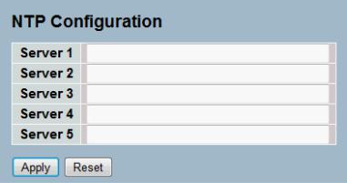
2-2.2 NTP
NTP is Network Time Protocol and is used to sync the network time based Greenwich Mean Time (GMT). If use the NTP mode and select a built-in NTP time server or manually specify an user-defined NTP server as well as Time Zone, the switch will sync the time in a short after pressing <Apply> button. Though it synchronizes the time automatically, NTP does not update the time periodically without user’s processing.
Time Zone is an offset time off GMT. You have to select the time zone first and then perform time sync via NTP because the switch will combine this time zone offset and updated NTP time to come out the local time, otherwise, you will not able to get the correct time. The switch supports configurable time zone from –12 to +13 step 1 hour.
Default Time zone: +8 Hrs.
Web Interface
To configure Time in the web interface:
1.Click SYSTEM, NTP.
2.Specify the Time parameter in manual parameters.
3.Click Save.
Figure 2-2.2: The NTP configuration
Parameter description:
Server 1to 5 :
Provide the NTP IPv4 or IPv6 address of this switch. IPv6 address is in 128-bit records represented as eight fields of up to four hexadecimal digits with a colon separating each field (:). For example, 'fe80::215:c5ff:fe03:4dc7'. The symbol '::' is a special syntax that can be used as a shorthand way of representing multiple 16-bit groups of contiguous zeros; but it can only appear once. It can also represent a legally valid IPv4 address. For example, '::192.1.2.34'.
Buttons
These buttons are displayed on the NTP page:
Save – Click to save changes.
Reset - Click to undo any changes made locally and revert to previously saved values.
10
2-3 Account
In this function, only administrator can create, modify or delete the username and password. Administrator can modify other guest identities’ password without confirming the password but it is necessary to modify the administrator-equivalent identity. Guest-equivalent identity can modify his password only. Please note that you must confirm administrator/guest identity in the field of Authorization in advance before configuring the username and password. Only one administrator is allowed to exist and unable to be deleted. In addition, up to 4 guest accounts can be created.
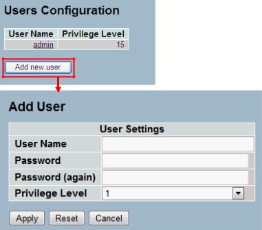
2-3.1 Users
This page provides an overview of the current users. Currently the only way to login as another user on the web server is to close and reopen the browser
Web Interface
To configure Account in the web interface:
1.Click SYSTEM, Account, Users.
2.Click Add new user
3.Specify the User Name parameter.
4.Click Save.
Figure2- 3.1: The Users Account configuration
Parameter description:
User Name :
The name identifying the user. This is also a link to Add/Edit User.
Password
To type the password. The allowed string length is 0 to 255, and the allowed content is the ASCII characters from 32 to 126.
Password (again)
To type the password again. You must type the same password again in the field.
11
Privilege Level :
The privilege level of the user. The allowed range is 1 to 15. If the privilege level value is 15, it can access all groups, i.e. that is granted the fully control of the device. But others value need to refer to each group privilege level. User's privilege should be same or greater than the group privilege level to have the access of that group. By default setting, most groups privilege level 5 has the read-only access and privilege level 10 has the read-write access. And the system maintenance (software upload, factory defaults and etc.) need user privilege level 15. Generally, the privilege level 15 can be used for an administrator account, privilege level 10 for a standard user account and privilege level 5 for a guest account.
12

2-3.2 Privitege Level
This page provides an overview of the privilege levels. The switch provides user set Account, Aggregation, Diagnostics ,EEE, GARP, GVRP, IP, IPMC Snooping LACP LLDP LLDP MED MAC Table MRP MVR MVRP Maintenance Mirroring POE Ports Private VLANs QoS SMTP SNMP Security Spanning Tree System Trap Event VCL VLANs Voice VLAN Privilege Levels from 1 to 15 .
Web Interface
To configure Privilege Level in the web interface:
1.Click SYSTEM, Account, Privilege Level.
2.Specify the Privilege parameter.
3.Click Save.
Figure2- 3.2: The Privilege Level configuration
13
Parameter description:
Group Name
The name identifying the privilege group. In most cases, a privilege level group consists of a single module (e.g. LACP, RSTP or QoS), but a few of them contains more than one. The following description defines these privilege level groups in details:
System: Contact, Name, Location, Timezone, Log.
Security: Authentication, System Access Management, Port (contains Dot1x port, MAC based and the MAC Address Limit), ACL, HTTPS, SSH, ARP Inspection and IP source guard.
IP: Everything except 'ping'.
Port: Everything except 'VeriPHY'.
Diagnostics: 'ping' and 'VeriPHY'.
Maintenance: System Reboot, System Restore Default, System Password, Configuration Save, Configuration Load and Firmware Load. WebUsers, Privilege Levels and everything in Maintenance.
Privilege Levels
Every group has an authorization Privilege level for the following sub groups: configuration read-only, configuration/execute read-write, status/statistics read-only, status /statistics read-write (e.g. for clearing of statistics). User Privilege should be same or greater than the authorization Privilege level to have the access to that group.
14

2-4 IP
IP is an acronym for Internet Protocol. It is a protocol used for communicating data across an internet network.
IP is a "best effort" system, which means that no packet of information sent over is assured to reach its destination in the same condition it was sent. Each device connected to a Local Area Network (LAN) or Wide Area Network (WAN) is given an Internet Protocol address, and this IP address is used to identify the device uniquely among all other devices connected to the extended network.
The current version of the Internet protocol is IPv4, which has 32-bits Internet Protocol addresses allowing for in excess of four billion unique addresses. This number is reduced drastically by the practice of webmasters taking addresses in large blocks, the bulk of which remain unused. There is a rather substantial movement to adopt a new version of the Internet Protocol, IPv6, which would have 128-bits Internet Protocol addresses. This number can be represented roughly by a three with thirty-nine zeroes after it. However, IPv4 is still the protocol of choice for most of the Internet.
2-4.1 IPV4
The IPv4 address for the switch could be obtained via DHCP Server for VLAN 1. To manually configure an address, you need to change the switch's default settings to values that are compatible with your network. You may also need to a establish a default gateway between the switch and management stations that exist on another network segment.
Configure the switch-managed IP information on this page
The Configured column is used to view or change the IP configuration.
The Current column is used to show the active IP configuration.
Web Interface
To configure an IP address in the web interface:
1.Click System, IP Configuration.
2.Specify the IPv4 settings, and enable DNS proxy service if required.
3.Click Save.
Figure2- 4.1: The IP configuration
Parameter description:
DHCP Client :
15
Enable the DHCP client by checking this box. If DHCP fails and the configured IP address is zero, DHCP will retry. If DHCP fails and the configured IP address is non-zero, DHCP will stop and the configured IP settings will be used. The DHCP client will announce the configured System Name as hostname to provide DNS lookup.
IP Address :
Provide the IP address of this switch in dotted decimal notation.
IP Mask :
Provide the IP mask of this switch dotted decimal notation.
IP Router :
Provide the IP address of the router in dotted decimal notation.
SNTP Server :
Provide the IP address of the SNTP Server in dotted decimal notation.
DNS Server :
Provide the IP address of the DNS Server in dotted decimal notation.
VLAN ID :
Provide the managed VLAN ID. The allowed range is 1 to 4095.
DNS Proxy :
When DNS proxy is enabled, DUT will relay DNS requests to the current configured DNS server on DUT, and reply as a DNS resolver to the client device on the network.
16
 Loading...