


GSW-0890
8-Port 10/100/1000Mbps
w/ 2-Port SFP L2 Managed Switch
User Manual
Ver. 1.00 - 0609
The information in this document is subject to change without notice. Unless the explicit written permission of LevelOne Corporation, this document in whole or in part shall not be replicated or modified or amended or transmitted, in any from, or by any means manual, electric, electronic, electromagnetic, mechanical, optical or otherwise for any purpose.
DURATION OF HARDWARE WARRANTY
HARDWARE: In accordance with the provisions described under, LevelOne Corporation (hereinafter called “LevelOne”) warrants its hardware products (hereinafter referred to as "Product") specified herein to be for a period of twelve (12) months from the date of shipment.
Should a Product fail to perform during the effective warranty period as described above, LevelOne shall replace the defective Product or part, or delivering a functionally equivalent Product or part in receipt of customer’s request, provided that the customer complies with the return material authorization (RMA) procedures and returns all defective Product prior to installation of the replacements to LevelOne.
All defective Products must be returned to LevelOne with issuance of a Return Material Authorization number (RMA number) assigned to the reseller from whom the end customer originally purchased the Product. The reseller is responsible for ensuring the shipments are insured, with the transportation charges prepaid and the RMA number clearly marked on the outside of the package. LevelOne will not accept collect shipments or those returned without an RMA number.
LevelOne shall not be responsible for any software, firmware, information or memory data contained in, stored on or integrated with any Product returned to LevelOne pursuant to any warranty.
EXCLUSIONS. The warranty as mentioned above does not apply to the following conditions, in LevelOne’s judgment, it contains (1) customer does not comply with the manual instructions offered by LevelOne in installation, operation, repair or maintenance, (2) Product fails due to damage from unusual external or electrical stress, shipment, storage, accident, abuse or misuse, (3) Product is used in an extra hazardous environment or activities, (4) any serial number on the Product has been removed or defaced, (5) this warranty will be of no effect if the repair is via anyone other than LevelOne or the approved agents, or (6) In the event of any failures or delays by either party hereto in the performance of all or any part of this agreement due to acts of God, war, riot, insurrection, national emergency, strike, embargo, storm, earthquake, or other natural forces, or by the acts of anyone not a party to this agreement, or by the inability to secure materials or transportation, then the party so affected shall be executed from any further performance for a period of time after the occurrence as may reasonably be necessary to remedy the effects of that occurrence, but in no event more than sixty (60) days. If any of the stated events should occur, Party A shall promptly notify Party B in writing as soon as commercially practicable, but in no event more than twenty (20) business days and provide documentation evidencing such occurrence. In no event shall the maximum liability of LevelOne under this warranty exceed the purchase price of the Product covered by this warranty.
DISCLAIMER. EXCEPT AS SPECIFICALLY PROVIDED ABOVE AS REQUIRED “AS IS” AND THE WARRANTIES AND REMEDIES STATED ABOVE ARE EXCLUSIVE AND IN LIEU OF ALL OTHERS, ORAL OR WRITTEN, EXPRESS OR IMPLIED. ANY AND ALL OTHER WARRANTIES, INCLUDING IMPLIED WARRANTIES OF MERCHANTABILITY, FITNESS FOR A PARTICULAR PURPOSE AND NONINFRINGEMENT OR THIRD PARTY RIGHTS ARE EXPRESSLY EXCLUDED.
SOFTWARE LICENSE AGREEMENT
NOTICE: Please carefully read this Software License Agreement (hereinafter referred to as this “Agreement”) before copying or using the accompanying software or installing the hardware unit with pre-enabled software or firmware (each of which is referred to as “Software” in this Agreement). BY COPYING OR USING THE SOFTWARE, YOU ACCEPT ALL OF THE PROVISIONS AND CONDITIONS OF THIS AGREEMENT. THE PROVISIONS EXPRESSED IN THIS AGREEMENT ARE THE ONLY PROVISION UNDER WHICH LEVELONE WILL PERMIT YOU TO USE THE SOFTWARE. If you do not accept these provisions and conditions, please immediately return the unused software, manual and the related product. Written approval is NOT a prerequisite to the validity or enforceability of this Agreement and no solicitation of any such written approval by or on behalf of LevelOne shall be deemed as an inference to the contrary.
LICENSE GRANT. The end user (hereinafter referred to as “Licensee”) of the Software is granted a personal, non-sublicensable, nonexclusive, nontransferable license by LevelOne Corporation (“LevelOne”): (1) To use the LevelOne’s software (“Software”) in object code form solely on a single central processing unit owned or leased by Licensee or otherwise embedded in the equipment offered by LevelOne. (2) To copy the Software only for backup purposes in support of authorized use of the Software. (3) To use and copy the documentation related to the Software solely in support of authorized use of the Software by Licensee. The License applies to the Software only except other LevelOne’s software or hardware products. Without the prior written consent of LevelOne, Licensee has no right to receive any source code or design documentation with respect to the Software.
RESTRICTIONS ON USE; RESERVATION OF RIGHTS. The Software and related documentation are protected under copyright laws. LevelOne and/or its licensors retain all title and ownership in both the Software and its related documentation, including any revisions made by LevelOne. The copyright notice must be reproduced and included with any copy of any portion of the Software or related documentation. Except as expressly authorized above, Licensee shall not copy or transfer the Software or related documentation, in whole or in part. Licensee also shall not modify, translate, decompile, disassemble, use for any competitive analysis, reverse compile or reverse assemble all or any portion of the Software, related documentation or any copy. The Software and related documentation embody LevelOne’s confidential and proprietary intellectual property. Licensee is not allowed to disclose the Software, or any information about the operation, design, performance or implementation of the Software and related documentation that is confidential to LevelOne to any third party. Software and related documentation may be delivered to you subject to export authorization required by governments of Taiwan and other countries. You agree that you will not export or re-export any Software or related documentation without the proper export licenses required by the governments of affected countries.
LIMITED SOFTWARE WARRANTY. LevelOne warrants that any media on which the Software is recorded will be free from defects in materials under normal use for a period of twelve (12) months from date of shipment. If a defect in any such media should occur during the effective warranty period, the media may be returned to LevelOne, then LevelOne will replace the media. LevelOne shall not be responsible for the replacement of media if the failure of the media results from accident, abuse or misapplication of the media.
EXCLUSIONS. The warranty as mentioned above does not apply to the Software, which (1) customer does not comply with the manual instructions offered by LevelOne in installation, operation, or maintenance, (2) Product fails due to damage from unusual external or electrical stress, shipment, storage, accident, abuse or misuse, (3) Product is used in an extra hazardous environment or activities, (4) any serial number on the Product has been removed or defaced, or (5) this warranty will be of no effect if the repair is via anyone other than LevelOne or the authorized agents. The maximum liability of LevelOne under this warranty is confined to the purchase price of the Product covered by this warranty.
2

DISCLAIMER. EXCEPT AS PROVIDED ABOVE, THE SOFTWARE IS PROVIDED “AS IS ” AND LEVELONE AND ITS LICENSORS MAKE NO WARRANTIES, EXPRESS OR IMPLIED, WITH REPSECT TO THE SOFTWARE AND DOCUMENTAITON. LEVELONE AND ITS LICENSORS DISCLAIM ALL OTHER WARRANTIES, INCLUSIVE OF WITHOUT LIMITATION, IMPLIED WARRANTIES OR MERCHANTABILITY, FITNESS FOR A PARTICULAR PURPOSE AND NONINFRINGEMENT. FURTHER, LEVELONE DOES NOT WARRANT, GUARANTEE, OR MAKE ANY REPRESENTATIONS REGARDING THE USE, OR THE RESULTS OF THE USE, OF THE SOFTWARE OR RELATED WRITTEN DOCUMENTAITON IN TERMS OF CORRECTNESS, ACCURACY, RELIABILITY, OR OTHERWISE.
CONSEQUENTIAL DAMAGES. IN NO EVENT SHALL LEVELONE OR ITS AUTHORIZED RESELLER BE LIABLE TO LICENSEE OR ANY THIRD PARTY FOR (A) ANY MATTER BEYOND ITS REASONABLE CONTROL OR (B) ANY CONSEQUENTIAL, SPECIAL, INDIRECT OR INCIDENTAL DAMAGES ARISING OUT OF THIS LICENSE OR USE OF THE SOFTWARE PROVIDED BY LEVELONE, EVEN IF LEVELONE HAS BEEN NOTIFIED OF THE POSSIBILITY OF SUCH DAMAGES IN ADVANCE. IN NO EVENT SHALL THE LIABILITY OF LEVELONE IN CONNECTION WITH THE SOFTWARE OR THIS AGREEMENT EXCEED THE PRICE PAID TO LEVELONE FOR THE LICENSE.
TERM AND TERMINATION. The License is effective until terminated; however, all of the restrictions in regard to LevelOne’s copyright in the Software and related documentation will cease being effective at the date of expiration; Notwithstanding the termination or expiration of the term of this agreement, it is acknowledged and agreed that those obligations relating to use and disclosure of LevelOne’s confidential information shall survive. Licensee may terminate this License at any time by destroying the software together with all copies thereof. This License will be immediately terminated if Licensee fails to comply with any term and condition of the Agreement. Upon any termination of this License for any reason, Licensee shall discontinue to use the Software and shall destroy or return all copies of the Software and the related documentation.
GENERAL. This License shall be governed by and construed pursuant to the laws of Taiwan. If any portion hereof is held to be invalid or unenforceable, the remaining provisions of this License shall remain in full force and effect. Neither the License nor this Agreement is assignable or transferable by Licensee without LevelOne’s prior written consent; any attempt to do so shall be void. This License constitutes the entire License between the parties with respect to the use of the Software.
LICENSEE ACKNOWLEDGES THAT LICENSEE HAS READ THIS AGREEMENT, UNDERSTANDS IT, AND AGREES TO BE BOUND BY ITS TERMS AND CONDITIONS. LICENSEE FURTHER AGREES THAT THIS AGREEMENT IS THE ENTIRE AND EXCLUSIVE AGREEMENT BETWEEN LEVELONE AND LICENSEE.
3
Caution
Circuit devices are sensitive to static electricity, which can damage their delicate electronics. Dry weather conditions or walking across a carpeted floor may cause you to acquire a static electrical charge.
To protect your device, always:
•Touch the metal chassis of your computer to ground the static electrical charge before you pick up the circuit device.
•Pick up the device by holding it on the left and right edges only.
Electronic Emission Notices
Federal Communications Commission (FCC) Statement
This equipment has been tested and found to comply with the limits for a class A computing device pursuant to Subpart J of part 15 of FCC Rules, which are designed to provide reasonable protection against such interference when operated in a commercial environment.
European Community (CE) Electromagnetic Compatibility Directive
This equipment has been tested and found to comply with the protection requirements of European Emission Standard EN55022/EN60555-2 and the Generic European Immunity Standard EN50082-1.
EMC: EN55022(1988)/CISPR-22(1985) EN60555-2(1995)
EN60555-3 IEC1000-4-2(1995) IEC1000-4-3(1995) IEC1000-4-4(1995)
class A class A
4K V CD, 8KV, AD 3V/m
1KV – (power line), 0.5KV – (signal line)
4

About this user’s manual
In this user’s manual, it will not only tell you how to install and connect your network system but configure and monitor the GSW-0890 through the built-in CLI and web by RS-232 serial interface and Ethernet ports step-by-step. Many explanation in detail of hardware and software functions are shown as well as the examples of the operation for web-based interface and command-line interface (CLI).
Overview of this user’s manual
Chapter 1 “Introduction”
Chapter 2 “Installation”
Chapter 3 “Operation of Web-based Management”
Chapter 4 “Operation of CLI Management”
Chapter 5 “Maintenance”
5
|
Table of Contents |
|
1. |
INTRODUCTION ------------------------------------------------------------------------------ |
1 |
|
1-1. OVERVIEW ------------------------------------------------------------------------------------- |
1 |
|
1-2. CHECKLIST ------------------------------------------------------------------------------------- |
3 |
|
1-3. FEATURES -------------------------------------------------------------------------------------- |
3 |
|
1-4. PHYSICAL VIEW ------------------------------------------------------------------------------- |
5 |
|
1-4-1. Front Panel ----------------------------------------------------------------------------- |
5 |
|
1-4-2. Rear Panel ----------------------------------------------------------------------------- |
6 |
|
1-5. OPTIONAL MODULES ------------------------------------------------------------------------- |
7 |
2. |
INSTALLATION-------------------------------------------------------------------------------- |
8 |
|
2-1. STARTING SWITCH UP ------------------------------------------------------------------------ |
8 |
|
2-1-1. Hardware and Cable Installation -------------------------------------------------- |
8 |
|
2-1-2. 19-Inch Wiring Closet Rail Installing ------------------------------------------- |
10 |
|
2-1-3. Cabling Requirements ------------------------------------------------------------- |
10 |
|
2-1-3-1. TP Ports Cabling------------------------------------------------------------------------- |
11 |
|
2-1-3-2. 1000SX/LX SFP Module Cabling---------------------------------------------------- |
11 |
|
2-1-3-3. Switch Cascading Topology----------------------------------------------------------- |
12 |
|
2-1-4. Configuring the Management Agent-------------------------------------------- |
15 |
|
2-1-4-1. Serial RS-232 Port ---------------------------------------------------------------------- |
16 |
|
2-1-4-2. Ethernet Port ----------------------------------------------------------------------------- |
18 |
|
2-1-5. IP Address Assignment------------------------------------------------------------ |
19 |
|
2-2. TYPICAL APPLICATIONS -------------------------------------------------------------------- |
24 |
3. |
WEB-BASED MANAGEMENT ---------------------------------------------------------- |
26 |
|
3-1. OVERVIEW ----------------------------------------------------------------------------------- |
28 |
|
3-1-1. System Information----------------------------------------------------------------- |
31 |
|
3-1-2. IP Configuration --------------------------------------------------------------------- |
33 |
|
3-1-3. Time Configuration ----------------------------------------------------------------- |
36 |
|
3-1-4. Account Configuration ------------------------------------------------------------- |
39 |
|
3-1-5. Management Policy ---------------------------------------------------------------- |
40 |
|
3-1-6. Virtual Stack -------------------------------------------------------------------------- |
43 |
|
3-2. PORT CONFIGURATION --------------------------------------------------------------------- |
45 |
|
3-2-1.Port Status----------------------------------------------------------------------------- |
45 |
|
3-2-2. Port Configuration ------------------------------------------------------------------ |
50 |
|
3-2-3. Simple Counter---------------------------------------------------------------------- |
52 |
|
3-2-4. Detail Counter ----------------------------------------------------------------------- |
54 |
|
3-3. MIRROR--------------------------------------------------------------------------------------- |
57 |
|
3-4. BANDWIDTH MANAGEMENT---------------------------------------------------------------- |
58 |
|
3-5. QOS(QUALITY OF SERVICE) CONFIGURATION------------------------------------------ |
60 |
|
3-6. LOOP DETECTION --------------------------------------------------------------------------- |
68 |
|
3-7. SNMP CONFIGURATION ------------------------------------------------------------------- |
70 |
|
3-8. IGMP SNOOPING --------------------------------------------------------------------------- |
72 |
|
3-9. MAX. PACKET LENGTH --------------------------------------------------------------------- |
74 |
|
3-10. DHCP BOOT ------------------------------------------------------------------------------- |
75 |
|
3-11. VLAN---------------------------------------------------------------------------------------- |
76 |
|
3-11-1. VLAN Mode------------------------------------------------------------------------- |
76 |
|
3-11-2. Tag-based Group ------------------------------------------------------------------ |
79 |
|
3-11-3. Port-based Group ----------------------------------------------------------------- |
81 |
|
3-11-4. Tag Rule ----------------------------------------------------------------------------- |
83 |
|
3-12. MAC TABLE -------------------------------------------------------------------------------- |
85 |
|
6 |
|
3-13. GVRP CONFIGURATION ------------------------------------------------------------------ |
92 |
3-14. STP CONFIGURATION -------------------------------------------------------------------- |
97 |
3-14-1. STP Status-------------------------------------------------------------------------- |
97 |
3-14-2. STP Configuration ---------------------------------------------------------------- |
99 |
3-14-3. STP Port Configuration --------------------------------------------------------- |
101 |
3-15. TRUNKING CONFIGURATION ------------------------------------------------------------ |
104 |
3-16. 802.1X CONFIGURATION ---------------------------------------------------------------- |
111 |
3-17. ALARM CONFIGURATION----------------------------------------------------------------- |
121 |
3-18. CONFIGURATION -------------------------------------------------------------------------- |
124 |
3-19. DIAGNOSTICS ----------------------------------------------------------------------------- |
129 |
3-20. TFTP SERVER ---------------------------------------------------------------------------- |
132 |
3-21. LOG----------------------------------------------------------------------------------------- |
133 |
3-22. FIRMWARE UPGRADE -------------------------------------------------------------------- |
134 |
3-23. REBOOT------------------------------------------------------------------------------------ |
135 |
3-24. LOGOUT------------------------------------------------------------------------------------ |
136 |
4. CLI MANAGEMENT----------------------------------------------------------------------- |
137 |
4-1. OVERVIEW ---------------------------------------------------------------------------------- |
137 |
4-2. COMMANDS OF CLI ------------------------------------------------------------------------ |
139 |
4-2-1. Global Commands----------------------------------------------------------------- |
140 |
4-2-2. Local Commands ------------------------------------------------------------------ |
146 |
5. MAINTENANCE ------------------------------------------------------------------------------- |
228 |
5-1. RESOLVING NO LINK CONDITION -------------------------------------------------------- |
228 |
5-2. Q&A ----------------------------------------------------------------------------------------- |
228 |
APPENDIX A TECHNICAL SPECIFICATIONS------------------------------------------- |
229 |
APPENDIX B NULL MODEM CABLE SPECIFICATIONS ---------------------------- |
233 |
7
1. Introduction
1-1. Overview
GSW-0890, an 8-port Gigabit L2 Managed Switch, is a standard switch that meets all IEEE 802.3/u/x/z Gigabit, Fast Ethernet specifications. The switch included 6-Port 10/100/1000Mbps TP and 2-Port Gigabit TP/SFP Fiber management Ethernet switch. The switch can be managed through RS-232 serial port via directly connection, or through Ethernet port using CLI or Web-based management unit, associated with SNMP agent. With the SNMP agent, the network administrator can logon the switch to monitor, configure and control each port’s activity in a friendly way. The overall network management is enhanced and the network efficiency is also improved to accommodate high bandwidth applications. In addition, the switch features comprehensive and useful function such as QoS (Quality of Service), Spanning Tree, VLAN, Port Trunking, Bandwidth Control, Port Security, SNMP/RMON, IGMP Snooping capability via the intelligent software. It is suitable for both metro-LAN and office application.
In this switch, Port 7 and Port 8 include two types of media --- TP and SFP Fiber (LC, BiDi LC…); this port supports 10/100/1000Mbps TP or 1000Mbps SFP Fiber with auto-detected function. 1000Mbps SFP Fiber transceiver is used for highspeed connection expansion.
1000Mbps LC, Multi-Mode, SFP Fiber transceiver
1000Mbps LC, 10km, SFP Fiber transceiver
10/100/1000Mbps TP is a standard Ethernet port that meets all IEEE 802.3/u/x/z Gigabit, Fast Ethernet specifications. 1000Mbps SFP Fiber transceiver is a Gigabit Ethernet port that fully complies with all IEEE 802.3z and 1000BaseSX/LX standards.
1000Mbps Single Fiber WDM (BiDi) transceiver is designed with an optic Wavelength Division Multiplexing (WDM) technology that transports bi-directional full duplex signal over a single fiber simultaneously.
For upgrading firmware, please refer to the Section 3-21 or Section 4-2-2 for more details. The switch will not stop operating while upgrading firmware and after that, the configuration keeps unchanged.
1
Key Features
QoS: Support Quality of Service by the IEEE 802.1P standard. There are two priority queue and packet transmission schedule.
Spanning Tree: Support IEEE 802.1D, IEEE 802.1w (RSTP: Rapid Spanning Tree Protocol) standards.
VLAN: Support Port-based VLAN and IEEE802.1Q Tag VLAN. Support 256 active VLANs and VLAN ID 1~4094.
Port Trunking: Support static port trunking and port trunking with IEEE 802.3ad LACP.
Bandwidth Control: Support ingress and egress per port bandwidth control.
Port Security: Support allowed, denied forwarding and port security with MAC address.
SNMP/RMON: SNMP agent and RMON MIB. In the device, SNMP agent is a client software which is operating over SNMP protocol used to receive the command from SNMP manager (server site) and echo the corresponded data, i.e. MIB object.
Besides, SNMP agent will actively issue TRAP information when happened. RMON is the abbreviation of Remote Network Monitoring and is a branch of the SNMP MIB.
The device supports MIB-2 (RFC 1213), Bridge MIB (RFC 1493), RMON MIB (RFC 1757)-statistics Group 1,2,3,9, Ethernet-like MIB (RFC 1643), Ethernet MIB (RFC 1643) and so on.
IGMP Snooping: Support IGMP version 2 (RFC 2236): The function IGMP snooping is used to establish the multicast groups to forward the multicast packet to the member ports, and, in nature, avoid wasting the bandwidth while IP multicast packets are running over the network.
2
1-2. Checklist
Before you start installing the switch, verify that the package contains the following:
-GSW-0890
-Power Cord
-RS-232 Cable
-User Manual in CD-ROM
Please notify your sales representative immediately if any of the aforementioned items is missing or damaged.
1-3. Features
The GSW-0890, a standalone off-the-shelf switch, provides the comprehensive features listed below for users to perform system network administration and efficiently and securely serve your network.
•Hardware
•6 10/100/1000Mbps Auto-negotiation Gigabit Ethernet TP ports
•2 10/100/1000Mbps TP or 1000Mbps SFP Fiber dual media auto sense
•144KB on-chip frame buffer
•Jumbo frame support
•Programmable classifier for QoS (Layer 4/Multimedia)
•8K MAC address and 4K VLAN support (IEEE802.1Q)
•Per-port shaping, policing, and Broadcast Storm Control
•IEEE802.1Q-in-Q nested VLAN support
•Full-duplex flow control (IEEE802.3x) and half-duplex backpressure
•Extensive front-panel diagnostic LEDs; System: Power, TP Port1-8: LINK/ACT, 10/100/1000Mbps, SFP Port 7, 8: SFP(LINK/ACT)
•Management
•Supports concisely the status of port and easily port configuration
•Supports per port traffic monitoring counters
•Supports a snapshot of the system Information when you login
•Supports port mirror function
•Supports the static trunk function
3
•Supports 802.1Q VLAN
•Supports user management and limits three users to login
•Maximal packet length can be up to 9208 bytes for jumbo frame application
•Supports DHCP Broadcasting Suppression to avoid network suspended or crashed
•Supports to send the trap event while monitored events happened
•Supports default configuration which can be restored to overwrite the current configuration which is working on via web browser and CLI
•Supports on-line plug/unplug SFP modules
•Supports Quality of Service (QoS) for real time applications based on the information taken from Layer 2 to Layer 4, such as VoIP
•Built-in web-based management and CLI management, providing a more convenient UI for the user
•Supports port mirror function with ingress traffic
•Supports rapid spanning tree (802.1w RSTP)
•Supports 802.1X port security on a VLAN
•Supports user management and only first login administrator can configure the device. The rest of users can only view the switch
•SNMP access can be disabled and prevent from illegal SNMP access
•Supports Ingress, Non-unicast and Egress Bandwidth rating management with a resolution of 1Mbps
•The trap event and alarm message can be transferred via e-mail and mobile phone short message
•Supports diagnostics to let administrator knowing the hardware status
•Supports external loopback test to check if the link is ok
•TFTP for firmware upgrade, system log upload and config file import/export
•Supports remote boot the device through user interface and SNMP
•Supports network time synchronization and daylight saving
•Supports 120 event log records in the main memory and display on the local console
4

1-4. Physical View
Fig. 1-1 Full View
1-4-1. Front Panel
There are 8 TP Gigabit Ethernet ports and 2 SFP fiber ports for optional removable modules on the front panel of the switch. LED display area contains a Power LED, which indicates the power status and 8 ports working status of the switch.
TP Port Status: Link/ACT |
Gigabit Ethernet Port |
TP Port Status: SPEED |
SFP
Fiber
Port
Power Indication LED |
Fiber Port Status Indication LEDs |
RESET Button:
RESET button is used to reset the management system.
Fig. 1-2 Front View
5
• LED Indicators
|
LED |
|
Color |
|
Function |
|
System LED |
|
|
||
|
POWER |
|
Green |
|
Lit when +5V DC power is on and good |
|
CPU LED |
Green |
Blinks when CPU is activity |
||
|
10/100/1000Ethernet TP Port 1 to 8 LED |
||||
|
LINK/ACT |
|
Green |
|
Lit when connection with remote device is good |
|
|
|
Blinks when any traffic is present |
||
|
|
|
|
|
Off when cable connection is not good |
|
|
|
Green/ |
|
Lit green when 1000Mbps speed is active |
|
|
|
|
Lit ember when 100Mbps speed is active |
|
|
10/100/1000Mbps |
|
Amber |
|
|
|
|
|
Off when 10Mbps speed is active |
||
|
|
|
|
|
|
|
1000SX/LX Gigabit Fiber Port 7, 8 LED |
||||
|
SFP(LINK/ACT) |
|
Green |
|
Lit when connection with the remote device is good |
|
|
|
Blinks when any traffic is present |
||
|
|
|
|
|
Off when module connection is not good |
|
|
|
|
|
Table1-1 |
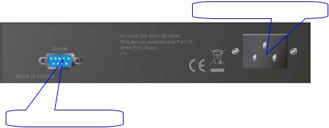
1-4-2. Rear Panel
One RS-232 DB-9 interface is offered for configuration or management.
AC Line 100-240V 50/60 Hz
RS-232 DB-9 Connector
Fig. 1-3 Rear View
6
1-5. Optional Modules
In the switch, Port 7~8 includes two types of media --- TP and SFP Fiber (LC, BiDi LC…); this port supports 10/100/1000Mbps TP or 1000Mbps SFP Fiber with auto-detected function. 1000Mbps SFP Fiber transceiver is used for high-speed connection expansion; the following are optional SFP types provided for the switch:
GVT-0300 1000Base mini-GBIC Fiber transceiver, LC, MM 550m
GVT-0301 1000Base mini-GBIC Fiber transceiver, LC, SM 10km
GVT-0302 1000Base mini-GBIC Fiber transceiver, LC, SM 70km
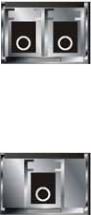
Fig. 1-4 1000Base-SX/LX LC, SFP Fiber Transceiver
Fig. 1-5 1000Base-LX BiDi LC, SFP Fiber Transceiver
7
2. Installation
2-1. Starting switch Up
This section will give users a quick start for:
-Hardware and Cable Installation
-Management Station Installation
-Software booting and configuration
2-1-1. Hardware and Cable Installation
At the beginning, please do first:
Wear a grounding device to avoid the damage from electrostatic discharge
Be sure that power switch is OFF before you insert the power cord to power source
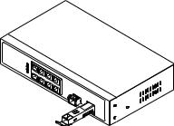
• Installing Optional SFP Fiber Transceivers
Note: If you have no modules, please skip this section.
Fig. 2-1 Installation of Optional SFP Fiber Transceiver
• Connecting the SFP Module to the Chassis:
The optional SFP modules are hot swappable, so you can plug or unplug it before or after powering on.
1.Verify that the SFP module is the right model and conforms to the chassis
2.Slide the module along the slot. Also be sure that the module is properly seated against the slot socket/connector
3.Install the media cable for network connection
4.Repeat the above steps, as needed, for each module to be installed into slot(s)
5.Have the power ON after the above procedures are done
8
•TP Port and Cable Installation
In the switch, TP port supports MDI/MDI-X auto-crossover, so both types of cable, straight-through (Cable pin-outs for RJ-45 jack 1, 2, 3, 6 to 1, 2, 3, 6 in 10/100M TP; 1, 2, 3, 4, 5, 6, 7, 8 to 1, 2, 3, 4, 5, 6, 7, 8 in Gigabit TP) and crossed-over (Cable pin-outs for RJ-45 jack 1, 2, 3, 6 to 3, 6, 1, 2) can be used. It means you do not have to tell from them, just plug it.
Use Cat. 5 grade RJ-45 TP cable to connect to a TP port of the switch and the other end is connected to a network-aware device such as a workstation or a server.
Repeat the above steps, as needed, for each RJ-45 port to be connected to a Gigabit 10/100/1000 TP device.
Now, you can start having the switch in operation.
• Power On
The switch supports 100-240 VAC, 50-60 Hz power supply. The power supply will automatically convert the local AC power source to DC power. It does not matter whether any connection plugged into the switch or not when power on, even modules as well. After the power is on, all LED indicators will light up immediately and then all off except the power LED still keeps on. This represents a reset of the system.
• Firmware Loading
After resetting, the bootloader will load the firmware into the memory. It will take about 30 seconds, after that, the switch will flash all the LED once and automatically performs self-test and is in ready state.
9
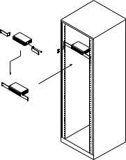
2-1-2. 19-Inch Wiring Closet Rail Installing
Fig. 2-2
Caution: Allow a proper spacing and proper air ventilation for the cooling fan at both sides of the chassis.
Wear a grounding device for electrostatic discharge.
Screw the mounting accessory to the front side of the switch (See Fig. 2-2).
Place the Chassis into the 19-inch wiring closet rail and locate it at the proper position. Then, fix the Chassis by screwing it.
2-1-3. Cabling Requirements
To help ensure a successful installation and keep the network performance good, please take a care on the cabling requirement. Cables with worse specification will render the LAN to work poorly.
10

2-1-3-1. TP Ports Cabling
For Fast Ethernet TP network connection
The grade of the cable must be Cat. 5 or Cat. 5e with a maximum length of 100 meters.
Gigabit Ethernet TP network connection
The grade of the cable must be Cat. 5 or Cat. 5e with a maximum length of 100 meters. Cat. 5e is recommended.
2-1-3-2. 1000SX/LX SFP Module Cabling
It is more complex and comprehensive contrast to TP cabling in the fiber media. Basically, there are two categories of fiber, multi mode (MM) and single mode (SM). The later is categorized into several classes by the distance it supports. They are SX, LX, LHX, XD, and ZX. From the viewpoint of connector type, there mainly are LC and BIDI LC.
Gigabit Fiber with multi-mode LC SFP module
Gigabit Fiber with single-mode LC SFP module
Gigabit Fiber with BiDi LC 1310nm SFP module
Gigabit Fiber with BiDi LC 1550nm SFP module
The following table lists the types of fiber that we support and those else not listed here are available upon request.
|
|
Multi-mode Fiber Cable and Modal Bandwidth |
|||||||
|
|
|
|
|
|
|
|
||
|
IEEE 802.3z |
Multi-mode 62.5/125μm |
|
|
Multi-mode 50/125μm |
||||
|
|
|
|
|
|
|
|
|
|
Modal |
|
|
|
|
Modal |
|
|
||
|
Gigabit Ethernet |
|
Distance |
|
|
|
Distance |
||
|
Bandwidth |
|
Bandwidth |
|
|||||
|
1000SX 850nm |
|
|
|
|
||||
|
160MHz-Km |
|
220m |
400MHz-Km |
|
500m |
|||
|
|
|
|
||||||
|
|
|
|
|
|
|
|
|
|
|
|
200MHz-Km |
|
275m |
500MHz-Km |
|
550m |
||
|
|
|
|
|
|
|
|
|
|
|
1000Base- |
Single-mode Fiber 9/125μm |
|
|
|
|
|
||
|
|
|
|
|
|
|
|
|
|
|
Single-mode transceiver 1310nm |
10Km |
|
||||||
|
LX/LHX/XD/ZX |
|
|||||||
|
|
|
|
|
|
|
|
|
|
|
|
Single-mode transceiver 1550nm |
30, 50Km |
|
|||||
|
|
|
|
|
|
|
TX(Transmit) |
1310nm |
|
|
|
Single-Mode |
|
|
|||||
|
1000Base-LX |
|
*20Km |
|
|
RX(Receive) |
1550nm |
||
|
Single Fiber |
|
|
|
|
|
|
|
|
|
|
|
|
|
|
TX(Transmit) |
1550nm |
||
|
(BIDI LC) |
Single-Mode |
|
|
|||||
|
|
|
*20Km |
|
|
RX(Receive) |
1310nm |
||
|
|
|
|
|
|
|
|
|
|
Table2-1
11

2-1-3-3. Switch Cascading Topology
• Takes the Delay Time into Account
Theoretically, the switch partitions the collision domain for each port in switch cascading that you may up-link the switches unlimitedly. In practice, the network extension (cascading levels & overall diameter) must follow the constraint of the IEEE 802.3/802.3u/802.3z and other 802.1 series protocol specifications, in which the limitations are the timing requirement from physical signals defined by 802.3 series specification of Media Access Control (MAC) and PHY, and timer from some OSI layer 2 protocols such as 802.1d, 802.1q, LACP and so on.
The fiber, TP cables and devices’ bit-time delay (round trip) are as follows:
1000Base-X TP, Fiber |
|
100Base-TX TP |
|
100Base-FX Fiber |
||||
Round trip Delay: 4096 |
|
Round trip Delay: 512 |
||||||
|
|
|
|
|
|
|
|
|
Cat. 5 TP Wire: |
11.12/m |
|
Cat. 5 TP Wire: |
1.12/m |
|
Fiber Cable: |
1.0/m |
|
Fiber Cable |
: |
10.10/m |
|
TP to fiber Converter: 56 |
|
|
|
|
Bit Time unit |
: 1ns (1sec./1000 Mega bit) |
|
Bit Time unit: 0.01μs (1sec./100 Mega bit) |
|||||
|
|
|
|
|
|
|
|
|
Table 2-2
Sum up all elements’ bit-time delay and the overall bit-time delay of wires/devices must be within Round Trip Delay (bit times) in a half-duplex network segment (collision domain). For full-duplex operation, this will not be applied. You may use the TP-Fiber module to extend the TP node distance over fiber optic and provide the long haul connection.
• Typical Network Topology in Deployment
A hierarchical network with minimum levels of switch may reduce the timing delay between server and client station. Basically, with this approach, it will minimize the number of switches in any one path; will lower the possibility of network loop and will improve network efficiency. If more than two switches are connected in the same network, select one switch as Level 1 switch and connect all other switches to it at Level 2. Server/Host is recommended to connect to the Level 1 switch. This is general if no VLAN or other special requirements are applied.
12
Case1: All switch ports are in the same local area network. Every port can access each other (See Fig. 2-3).
Fig. 2-3 No VLAN Configuration Diagram
If VLAN is enabled and configured, each node in the network that can communicate each other directly is bounded in the same VLAN area.
Here VLAN area is defined by what VLAN you are using. The switch supports both port-based VLAN and tag-based VLAN. They are different in practical deployment, especially in physical location. The following diagram shows how it works and what the difference they are.
Case2a: Port-based VLAN (See Fig.2-4).
Fig. 2-4 Port-based VLAN Diagram
1.The same VLAN members could not be in different switches.
2.Every VLAN members could not access VLAN members each other.
3.The switch manager has to assign different names for each VLAN groups at one switch.
13

Case 2b: Port-based VLAN (See Fig.2-5).
Fig. 2-5 Port-based VLAN Diagram
1.VLAN1 members could not access VLAN2, VLAN3 and VLAN4 members.
2.VLAN2 members could not access VLAN1 and VLAN3 members, but they could access VLAN4 members.
3.VLAN3 members could not access VLAN1, VLAN2 and VLAN4.
4.VLAN4 members could not access VLAN1 and VLAN3 members, but they could access VLAN2 members.
Case3a: The same VLAN members can be at different switches with the same VID (See Fig. 2-6).
Fig. 2-6 Attribute-based VLAN Diagram
14
2-1-4. Configuring the Management Agent
We offer you three ways to startup the switch management function. They are RS-232 console, CLI, and Web. Users can use any one of them to monitor and configure the switch. You can touch them through the following procedures.
Section 2-1-4-1: Configuring through the Serial RS-232 Port Section 2-1-4-2: Configuring through the Ethernet Port
Note: Please first modify the IP address, Subnet mask, Default gateway and DNS through RS-232 console, and then do the next.
15
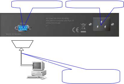
2-1-4-1. Serial RS-232 Port
To perform the configuration through RS-232 console port, the switch’s serial port must be directly connected to a DCE device, for example, a PC, through RS-232 cable with DB-9 connector. Next, run a terminal emulator with the default setting of the switch’s serial port. With this, you can communicate with the switch.
In the switch, RS-232 interface only supports baud rate 57.6k bps with 8 data bits, 1 stop bit, no parity check and no flow control.
RS-232 DB-9 Connector |
AC Line 100-240V 50/60 Hz |
RS-232
GSW-0890 L2 Managed Switch Default IP Setting:
IP address = 192.168.1.1 Subnet Mask = 255.255.255.0
Default Gateway = 192.168.1.254
Fig. 2-7 |
RS-232 cable with female |
|
DB-9 connector at both ends |
Terminal or Terminal Emulator |
|
To configure the switch, please follow the procedures below:
1.Find the RS-232 DB-9 cable with female DB-9 connector bundled. Normally, it just uses pins 2, 3 and 7. See also Appendix B for more details on Null Modem Cable Specifications.
2.Attaches the DB-9 female cable connector to the male serial RS-232 DB-9 connector on the switch.
3.Attaches the other end of the serial RS-232 DB-9 cable to PC’s serial port, running a terminal emulator supporting VT100/ANSI terminal with The switch’s serial port default settings. For example,
Windows98/2000/XP HyperTerminal utility.
Note: The switch’s serial port default settings are listed as follows:
Baud rate |
57600 |
Stop bits |
1 |
Data bits |
8 |
Parity |
N |
Flow control |
none |
4.When you complete the connection, then press <Enter> key. The login prompt will be shown on the screen. The default username and password are shown as below:
Username = admin |
Password = admin |
16

• Set IP Address, Subnet Mask and Default Gateway IP Address
Please refer to Fig. 2-7 CLI Management for details about LevelOne’s setting. They are default setting of IP address. You can first either configure your PC IP address or change IP address of the switch, next to change the IP address of default gateway and subnet mask.
For example, your network address is 10.1.1.0, and subnet mask is 255.255.255.0. You can change the switch’s default IP address 192.168.1.1 to 10.1.1.1 and set the subnet mask to be 255.255.255.0. Then, choose your default gateway, may be it is 10.1.1.254.
|
|
Default Value |
|
|
GSW-0890 |
|
|
|
Your Network Setting |
|
|
|
|
|
|
|
|
|
|
|
|
|
|
IP Address |
|
192.168.1.1 |
|
|
10.1.1.1 |
|
||
|
|
Subnet |
|
255.255.255.0 |
|
|
255.255.255.0 |
|
||
|
|
|
|
|
|
|
|
|
|
|
|
|
Default Gateway |
|
192.168.1.254 |
|
|
10.1.1.254 |
|
||
|
|
|
|
|
|
|
|
|
|
|
Table 2-3
After completing these settings in the switch, it will reboot to have the configuration taken effect. After this step, you can operate the management through the network, no matter it is from a web browser or Network Management System (NMS).
L2 Managed Switch - GSW-0890
Login: admin
Password:
GSW-0890$
Fig. 2-8 the Login Screen for CLI
17
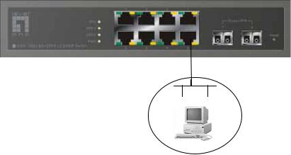
2-1-4-2. Ethernet Port
There are three ways to configure and monitor the switch through the switch’s Ethernet port. They are CLI, Web browser and SNMP manager. The user interface for the last one is NMS dependent and does not cover here. We just introduce the first two types of management interface.
GSW-0890 L2 Managed Switch
Default IP Setting:
IP = 192.168.1.1
Subnet Mask = 255.255.255.0
Default Gateway = 192.168.1.254
Assign a reasonable IP address, For example:
IP = 192.168.1.100
Subnet Mask = 255.255.255.0 Default Gateway = 192.168.1.254
Ethernet LAN
Fig. 2-9
• Managing through Ethernet port
Before you communicate with the switch, you have to finish first the configuration of the IP address or to know the IP address of the switch. Then,
follow the procedures listed below.
1.Set up a physical path between the configured the switch and a PC by a qualified UTP Cat. 5 cable with RJ-45 connector.
Note: If PC directly connects to the switch, you have to setup the same subnet mask between them. But, subnet mask may be different for the PC in the remote site. Please refer to Fig. 2-9 about the switch’s default IP address information.
2.Run CLI or web browser and follow the menu. Please refer to Chapter 3 and Chapter 4.
18
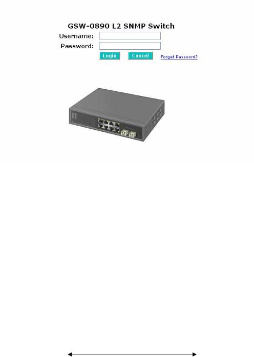
Fig. 2-10 the Login Screen for Web
2-1-5. IP Address Assignment
For IP address configuration, there are three parameters needed to be filled in. They are IP address, Subnet Mask, Default Gateway and DNS.
IP address:
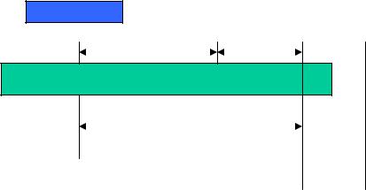
The address of the network device in the network is used for internetworking communication. Its address structure looks is shown in the Fig. 2-11. It is “classful” because it is split into predefined address classes or categories.
Each class has its own network range between the network identifier and host identifier in the 32 bits address. Each IP address comprises two parts: network identifier (address) and host identifier (address). The former indicates the network where the addressed host resides, and the latter indicates the individual host in the network which the address of host refers to. And the host identifier must be unique in the same LAN. Here the term of IP address we used is version 4, known as IPv4.
32 bits
Network identifier |
Host identifier |
|
|
Fig. 2-11 IP address structure
19

With the classful addressing, it divides IP address into three classes, class A, class B and class C. The rest of IP addresses are for multicast and broadcast. The bit length of the network prefix is the same as that of the subnet mask and is denoted as IP address/X, for example, 192.168.1.0/24. Each class has its address range described below.
Class A:
Address is less than 126.255.255.255. There are a total of 126 networks can be defined because the address 0.0.0.0 is reserved for default route and 127.0.0.0/8 is reserved for loopback function.
Bit # |
0 1 |
7 8 |
0
Network address Host address
Class B:
IP address range between 128.0.0.0 and 191.255.255.255. Each class B network has a 16-bit network prefix followed 16-bit host address. There are 16,384 (2^14)/16 networks able to be defined with a maximum of 65534 (2^16 –2) hosts per network.
Bit # |
01 2 |
15 16 |
10
Network address Host address
Class C:
IP address range between 192.0.0.0 and 223.255.255.255. Each class C network has a 24-bit network prefix followed 8-bit host address. There are 2,097,152 (2^21)/24 networks able to be defined with a maximum of 254 (2^8 –2) hosts per network.
Bit # 0 1 2 3 |
23 24 |
31 |
110
Network address Host
20
Class D and E:
Class D is a class with first 4 MSB (Most significance bit) set to 1-1-1-0 and is used for IP Multicast. See also RFC 1112. Class E is a class with first 4 MSB set to 1-1-1-1 and is used for IP broadcast.
According to IANA (Internet Assigned Numbers Authority), there are three specific IP address blocks reserved and able to be used for extending internal network. We call it Private IP address and list below:
Class A |
10.0.0.0 --- |
10.255.255.255 |
|
Class B |
172.16.0.0 |
--- |
172.31.255.255 |
Class C |
192.168.0.0 --- |
192.168.255.255 |
|
Please refer to RFC 1597 and RFC 1466 for more information. Subnet mask:
It means the sub-division of a class-based network or a CIDR block. The subnet is used to determine how to split an IP address to the network prefix and the host address in bitwise basis. It is designed to utilize IP address more efficiently and ease to manage IP network.
For a class B network, 128.1.2.3, it may have a subnet mask 255.255.0.0 in default, in which the first two bytes is with all 1s. This means more than 60 thousands of nodes in flat IP address will be at the same network. It’s too large to manage practically. Now if we divide it into smaller network by extending network prefix from 16 bits to, say 24 bits, that’s using its third byte to subnet this class B network. Now it has a subnet mask 255.255.255.0, in which each bit of the first three bytes is 1. It’s now clear that the first two bytes is used to identify the class B network, the third byte is used to identify the subnet within this class B network and, of course, the last byte is the host number.
Not all IP address is available in the sub-netted network. Two special addresses are reserved. They are the addresses with all zero’s and all one’s host number. For example, an IP address 128.1.2.128, what IP address reserved will be looked like? All 0s mean the network itself, and all 1s mean IP broadcast.
128.1.2.128/25
Network Subne
10000000.00000001.00000010.1 0000000
25 bits |
|
All 0s = 128.1.2.128 |
1 0000000 |
All 1s= 128.1.2.255 |
1 1111111 |
|
21

In this diagram, you can see the subnet mask with 25-bit long, 255.255.255.128, contains 126 members in the sub-netted network. Another is that the length of network prefix equals the number of the bit with 1s in that subnet mask. With this, you can easily count the number of IP addresses matched. The following table shows the result.
Prefix Length
 No. of IP matched
 No. of Addressable IP
|
/32 |
1 |
- |
|
|
|
|
|
|
|
|
|
|
|
|
/31 |
2 |
- |
|
|
|
|
|
|
|
|
|
|
|
|
/30 |
4 |
2 |
|
|
|
|
|
|
|
|
|
|
|
|
/29 |
8 |
6 |
|
|
|
|
|
|
|
|
|
|
|
|
/28 |
16 |
14 |
|
|
|
|
|
|
|
|
|
|
|
|
/27 |
32 |
30 |
|
|
|
|
|
|
|
|
|
|
|
|
/26 |
64 |
62 |
|
|
|
|
|
|
|
|
|
|
|
|
/25 |
128 |
126 |
|
|
|
|
|
|
|
|
|
|
|
|
/24 |
256 |
254 |
|
|
|
|
|
|
|
|
|
|
|
|
/23 |
512 |
510 |
|
|
|
|
|
|
|
|
|
|
|
|
/22 |
1024 |
1022 |
|
|
|
|
|
|
|
|
|
|
|
|
/21 |
2048 |
2046 |
|
|
|
|
|
|
|
|
|
|
|
|
/20 |
4096 |
4094 |
|
|
|
|
|
|
|
|
|
|
|
|
/19 |
8192 |
8190 |
|
|
|
|
|
|
|
|
|
|
|
|
/18 |
16384 |
16382 |
|
|
|
|
|
|
|
|
|
|
|
|
/17 |
32768 |
32766 |
|
|
|
|
|
|
|
|
|
|
|
|
/16 |
65536 |
65534 |
|
|
|
|
|
|
|
|
|
|
|
|
|
Table 2-4 |
|
|
According to the scheme above, a subnet mask 255.255.255.0 will partition a network with the class C. It means there will have a maximum of 254 effective nodes existed in this sub-netted network and is considered a physical network in an autonomous network. So it owns a network IP address which may looks like 168.1.2.0.
With the subnet mask, a bigger network can be cut into small pieces of network. If we want to have more than two independent networks in a worknet, a partition to the network must be performed. In this case, subnet mask must be applied.
22
 Loading...