


FEP-0811
8-Port Fast Ethernet PoE Switch
FEP-0812
8-Port Fast Ethernet PoE Switch
GEP-0812
8-Port Gigabit Ethernet PoE Switch
GEP-0820/GEP-0821/GEP-0822
8-Port Gigabit PoE Switch
GEP-1020/GEP-1021
8 GE PoE-Plus + 2 GE SFP Switch
Quick Installation Guide
English |
Português |
Deutsch |
Svenska |
Français |
Slovenščina |
Español |
|
Nederlands |
|
Dansk |
Русский |
Italiano |
Polski |
Ελληνικά |
|
|
1 |

Hardware Installation Figures
Rack Mounting
Flat Surface Installation
Power Regulation
Input : AC 100-240V; 50/60Hz
2

ENGLISH
Installation
Power Link/Act
SFP
LED Indicator
LED |
Status |
Meaning |
|
|
|||
Indicator |
|
|
|
|
On |
Power is on. |
|
Power |
|
|
|
Off |
Power is off. |
||
|
|||
|
|
|
|
|
On |
Port is connected |
|
|
|
|
|
Link/Act |
Blinking |
Transmitting / Receiving data |
|
|
Off |
Port is not connected |
|
|
|
|
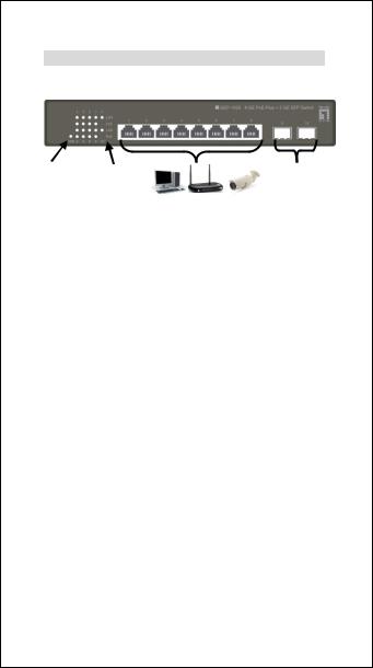
Connecting Equipment
Step1.Inspect the Power Adapter carefully, and make sure that it is properly connected to a power source.
Step2.Plug-in the Power Adapter to the Switch. Step3.Connect your network devices with the switch
by using Ethernet cable. (e.g. Cat-5e)
3

Deutsch
Installation
Power |
Link/Aktivität |
SFP |
|
||
|
|
LED-Anzeige
LED-Anzeige |
Status |
Bedeutung |
|
|
|
||
|
On |
Power ist an. |
|
Power |
|
|
|
Off |
Power ist aus. |
||
|
|||
|
|
|
|
|
On |
Port ist verbunden. |
|
|
|
|
|
Link/Aktivität |
Blinken |
Senden/Empfangen von |
|
Daten |
|||
|
|
||
|
|
|
|
|
Off |
Port ist nicht verbunden. |
|
|
|
|
Anschluss der Geräte
Schritt1. Bitte prüfen Sie die korrekte Verbindung des Netzteils mit der Steckdose.
Schritt2. Verbinden Sie das Netzteil mit dem Switch. Schritt3. Verbinden Sie weitere Geräte mit dem
Switch unter Verwendung von Ethernet-Kabeln (z.B.: Cat.5e).
4

Français
Installation physique
Alimentation |
Lien/Act |
SFP |
|
|
Indicateur DEL
Indicateur |
É tat |
Signification |
|
|
|||
DEL |
|
|
|
|
Marche |
Sous tension. |
|
Alimentation |
|
|
|
Arrêt |
Hors tension. |
||
|
|||
|
|
|
|
|
Marche |
Le port est connecté |
|
|
|
|
|
Lien/Act |
Clignotan |
Transmission/Réception de |
|
t |
données en cours |
||
|
|||
|
|
|
|
|
Arrêt |
Le port n'est pas connecté |
|
|
|
|
Branchement de l'équipement
Étape1. Inspectez soigneusement l'adaptateur secteur et assurez-vous qu'il est correctement connecté à une source d'alimentation.
Étape2. Branchez l'adaptateur secteur sur le switch.
Étape3. Connectez vos périphériques réseau au switch en utilisant un câble Ethernet. (Par exemple, Cat-5e)
5
Español
Instalación física
Potencia |
SFP |
|
Estado de conexíón |
||
|
Indicadores LED
Indicadores |
Estado |
Significado |
|
||
LED |
|
|
|
Encendido |
El dispositivo está |
Potencia |
encendido. |
|
|
|
|
|
Apagado |
El dispositivo está apagado. |
|
|
|
|
Encendido |
El Puerto está conectado. |
|
|
|
Estado de |
Intermitent |
Transmitiendo / Recibiendo |
conexíón |
e |
datos |
|
|
|
|
Apagado |
El Puerto no está conectado |
|
|
|
Procedimiento de conexión del equipo
Paso1. |
Inspeccione el adaptador de corriente |
con cuidado, y asegúrese de que está |
|
correctamente conectado a una fuente de |
|
energía. |
|
Paso2. |
Conecte el adaptador de corriente al |
Switch. |
|
Paso3. |
Conecte sus dispositivos de red con el |
switch mediante el uso de cable Ethernet.(Por ejemplo, Cat-5e).
6
 Loading...