


LevelOne FVS-3800, FVS-3200, FVS-3120, GVS-3200, GVS-3110 Quick Installation Guide
...Ethernet Media Converter
Web Smart Series
User Manual
v1.0 May. 2011
i

Ethernet Media Converter
Web Smart Series
FVS-3800, 10/100BASE-TX to 100BASE-X SFP Converter FVS-3200, 10/100BASE-TX to 100BASE-FX MMF SC Converter FVS-3120, 10/100BASE-TX to 100BASE-LX SMF SC Converter GVS-3800, 10/100/1000BASE-T to 1000BASE-X SFP Converter
GVS-3200, 10/100/1000BASE-T to 1000BASE-SX MMF SC Converter GVS-3110, 10/100/1000BASE-T to 1000BASE-LX10 SMF SC Converter CVH-3000, 12-Slot Media Converter Chassis
i
Table of Contents |
|
CAUTION.......................................................................................................................................... |
III |
ELECTRONIC EMISSION NOTICES.................................................................................................... |
III |
1. INTRODUCTION ............................................................................................................ |
2 |
1-1. OVERVIEW.................................................................................................................................. |
2 |
1-2. FEATURES ................................................................................................................................... |
2 |
1-3. CHECKLIST ................................................................................................................................. |
3 |
2. INSTALLATION .............................................................................................................. |
5 |
2-1. CABLE AND HARDWARE INSTALLATION (WEB SMART MEDIA CONVERTERS) .......................... |
5 |
2-2. CABLE AND HARDWARE INSTALLATION (WEB SMART MEDIA CONVERTER CHASSIS) ............. |
5 |
3. OPERATION OF WEB-BASED MANAGEMENT ...................................................... |
8 |
3-1. WEB MANAGEMENT HOME OVERVIEW ..................................................................................... |
9 |
3-2. THE FUNCTION TREE IN WEB MANAGEMENT.......................................................................... |
11 |
3-3. LOCAL SETTING ....................................................................................................................... |
12 |
3-3-1. IP Configuration ............................................................................................................ |
12 |
3-3-2. Password Setting............................................................................................................ |
14 |
3-3-3. Converter Configuration............................................................................................... |
15 |
3-3-4. Port Configuration......................................................................................................... |
17 |
3-3-5. MIB Counter .................................................................................................................. |
19 |
3-3-6. VLAN.............................................................................................................................. |
20 |
3-3-6-1. VLAN Group........................................................................................................................... |
20 |
3-3-6-2. VLAN Per Port Setting........................................................................................................... |
22 |
3-3-7. Q-in-Q............................................................................................................................. |
23 |
3-4. Remote Setting.................................................................................................................... |
29 |
3-4-1. TS-1000 Functions ......................................................................................................... |
29 |
3-4-1-1. TS-1000 Setting ....................................................................................................................... |
29 |
3-4-1-2. Loopback Test ......................................................................................................................... |
31 |
3-4-1-3. Remote Device Reset............................................................................................................... |
32 |
3-4-1-4. Remote Port Information ....................................................................................................... |
33 |
3-4-1-5. Remote Port Setting................................................................................................................ |
33 |
3-4-2. 802.3ah Function............................................................................................................ |
34 |
3-4-2-1. 802.3ah Configuration ............................................................................................................ |
34 |
3-4-2-2. Loopback Test ......................................................................................................................... |
35 |
3-4-2-3. 802.3ah Status.......................................................................................................................... |
36 |
3-5. TOOLS....................................................................................................................................... |
37 |
3-5-1. System Reboot................................................................................................................ |
37 |
3-5-2. Save and Restore............................................................................................................ |
38 |
3-5-3. Firmware Upgrade ........................................................................................................ |
39 |
3-5-4. Logout............................................................................................................................. |
39 |
4. MAINTENANCE............................................................................................................. |
40 |
4-1. RESOLVING NO LINK CONDITIONS........................................................................................... |
40 |
4-2. Q&A ........................................................................................................................................ |
40 |
APPENDIX A TECHNICAL SPECIFICATIONS ........................................................... |
41 |
ii
Caution
Circuit devices are sensitive to static electricity, which can damage their delicate electronics. Dry weather conditions or walking across a carpeted floor may cause you to acquire a static electrical charge.
To protect your device, always:
•Touch the metal chassis of your computer to ground the static electrical
charge before you pick up the circuit device.
•Pick up the device by holding it on the left and right edges only.
Electronic Emission Notices
Federal Communications Commission (FCC) Statement
This equipment has been tested and found to comply with the limits for a class A computing device pursuant to Subpart J of part 15 of FCC Rules, which are designed to provide reasonable protection against such interference when operated in a commercial environment.
European Community (CE) Electromagnetic Compatibility Directive
This equipment has been tested and found to comply with the protection requirements of European Emission Standard EN55022/EN60555-2 and the Generic European Immunity Standard EN50082-1.
EMC: EN55022(1988) /CISPR-22(1985) EN60555-2(1995)
EN60555-3 IEC1000-4-2(1995) IEC1000-4-3(1995) IEC1000-4-4(1995)
class A class A
4K V CD, 8KV, AD 3V/m
1KV – (power line), 0.5KV – (signal line)

About this user’s manual
In this user’s manual, it will not only tell you how to install and connect your network system but configure and monitor the Web Smart MEDIA CONVERTER through the built-in web by Ethernet ports step-by-step. Many explanations in detail of hardware and software functions are shown as well as the examples of the operation for webbased interface.
Overview of this user’s manual
Chapter 1 “Introduction” describes the features of Web Smart MEDIA CONVERTER
Chapter 2 “Installation”
Chapter 3 “Operation of Web-based Management”
Chapter 4 “Maintenance”
Appendix A
1
1. Introduction
1-1. Overview
The LevelOne Media Converter-Web Smart Series is designed to make conversion between 10/100Base-TX and 100Base-FX or 10/100/1000Base-TX and 100/1000Base-FX Ethernet. With web-based management and Telnet text-based manual driven management, the network administrator can logon the remotely converter to monitor, configure and control the status of each unit. The overall network reliability is enhanced, and the network efficiency is also improved to accommodate and deliver high bandwidth applications.
The 19-inch Media Converter Rack, CVH-3000, is designed to accommodate 12 units of various type of web smart media converter at a central location for multiple segments cross connection. DC −48V power supply is used and provided by Telecom site. The Rack provides solutions for users to best manage media converters. Since converter is connected directly to the chassis main-board, no power cable or wire is required for connection. Moreover, a redundant power supply is offered in the power supply set to cope with any accidental breakdown of power supply.
1-2. Features
The Web Smart Media Converter provides the following features for users to perform system network administration.
Management
•Supports Web UI for management
•Supports OAM for remote management via TS-1000
•Supports OAM for remote management via IEEE802.3ah
•Supports Ingress/Egress Rate Limitation
•Supports Link Loss Carry Forward Function
•Supports per Port MIB Counters
•Supports IEEE802.1Q VLAN
•Supports Q-in-Q (Double-Tag) VLAN
•Supports 802.3x flow control for full-duplex ports and backpressure for half-duplex ports
•Supports auto mode on the TP port
•Supports jumbo frame 9KB
•RoHS Compliance
•On-board firmware can be updated via HTTP web function.
•The converter allows administrator to reboot system from management station.
•Dying Gasp function can send out a signal when DC power down is detected.
2

1-3. Checklist
Before you start installing the converter, please verify that the package contains the following:
Web Smart Media Converters:
Web Smart Media Converter
AC-DC Power adapter
This User's Manual (CD)
Web Smart Media Converters Chassis:
The Media Converter Rack
Mounting Accessory (for 19" Rack Shelf) and Rubber feet (if not using Rack Shelf)
This User's Manual
AC Power Cord
Please notify your sales representative immediately if any of the aforementioned items is missing or damaged.
Model Description
Model |
Description |
|
FVS-3800 |
10/100BASE-TX to 100BASE-X SFP Converter |
|
FVS-3200 |
10/100BASE-TX to 100BASE-FX MMF SC Converter |
|
FVS-3120 |
10/100BASE-TX to 100BASE-LX SMF SC Converter |
|
GVS-3800 |
10/100/1000BASE-T to 1000BASE-X SFP Converter |
|
GVS-3200 |
10/100/1000BASE-T to 1000BASE-SX MMF SC Converter |
|
GVS-3110 |
10/100/1000BASE-T to 1000BASE-LX10 SMF SC Converter |
|
CVH-3000 |
12-Slot Media Converter Chassis |
3

Function
Lit when +5V power is coming up
Lit when fiber connection is good
Blinks when any traffic is present
TP LINK/ACT Green Lit when TP connection is good Blinks when any traffic is present
TP 10/100 Amber Lit when 100Base-TX is active Off when 10Base-T is active
Table 1-1
Reset button:
Press this button over 5 seconds then
(1)Restore to default
(2)Reboot
4
2. Installation
2-1. Cable and Hardware Installation
(Web Smart Media Converters)
Wear a grounding device for electrostatic discharge
Verify that the AC-DC adapter conforms to your country AC power requirement and then insert the power plug
• TP Cable
Use Cat. 5 TP cable to connect server/host or workstation to TP port of the converter
TP port supports MDI/MDI-X auto-crossover, use:
straight-through cable (Cable pin-outs for RJ-45 jack 1, 2, 3, 6 to 1, 2, 3, 6) to cascade or up-link the converter to an upper layer L2/L3 switch or server/host/workstation
TP Cable Limitations: Cat. 5 and up to 100m
• Fiber Cable
Use fiber cable to connect FX port of an upper layer converter
Fiber Cable Limitations:
SC Converter Models
Multi-mode Half-duplex |
412m |
Multi-mode Full-duplex |
2Km |
Single-mode Half-duplex |
412m |
Single-mode Full-duplex |
10/30/50Km |
Table 2-1
Note: The other side of the fiber cable plugged into the converter’s RX connector at the near end should plug into the FX device’s TX connector at the far end, and vice versa.
2-2. Cable and Hardware Installation
(Web Smart Media Converter Chassis)
 2.5mm
2.5mm
DC Receptacle 2.5mm 1A@+5V for each slot
DC receptacle is 2.5mm wide that matches and conforms to the Media Converter 2.5mm DC jack's central post. Do not install any improper unit or model of the Media Converter.
The slide-in Media Converters and Converter Rack should be supplied only from the same source; both Media Converters and Rack are built to match each other at dimensions, DC power jack, DC receptacle and power safety.
Turn off the 19" converter rack power.
Verify the Media Converter is right for this Rack and locate +5VDC power jack on converter back, and carefully slide in and plug to match 19" rack slot +5VDC receptacle.
5

Fig. 1 Front/Rear View of 19-inch
Fig. 2 The hot-swappable parts
Fig. 3 Installing Rack
Fig. 4 Usage of 8cm FAN connector
6
Installing Media Converter Rack to a Wiring Closet Rack
Wear a grounding device for electrostatic discharge
Install screws through mounting ears into each side
Locate Converter Rack at 19-inch mounting rails and screw up the front brackets
Set the Power Switch at "OFF" position before connecting with the power cord
Two power modules, 12 converter modules and two 8cm DC Fans are Hot-Swappable
7
3. Operation of Web-based
Management
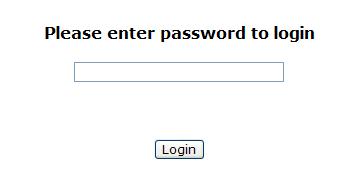
The converter provides a web function by Ethernet Port (Browser) to manage and monitor the port activity. For instance, http://192.168.1.1, then enter password and CLICK “Login” button.
The default values of Web Smart Media Converter are as follows:
IP Address |
:192.168.1.1 |
Subnet Mask |
:255.255.255.0 |
Default Gateway |
:192.168.1.254 |
Password |
:admin |
Fig. 3-1
8
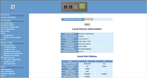
3-1. Web Management Home Overview
Home Page and Main MENU will be shown up after you fill in “admin” to serve as password and click the <Login> button. The main functions will be listed on the left side of a browser. On the top is the front panel view of the converter. In the middle is the basic System Information. The main functions will be introduced in the following sections.
On the front panel, the LEDs will display the status color which is the same as physical hardware. The fiber and TP plug will display the status color as well. Green stands for “Link up” status.
The main functions are “Information”, “Local Settin g”, “Remote Setting”, and “Tools”.
Function name:
System Information
Function description:
Show the local and remote device network information.
Fig. 3-2
Parameter description:
Remote Device Control:
Disable (Default):
When Remote Device Control is disabled, the remote device information will not be shown on the screen.
Enable:
When Remote Device Control is enabled, the remote device information will be shown on the screen.
MAC address:
It is the Ethernet MAC address of the management agent in this device.
9
 Loading...