

Page 1
Inverter
8400
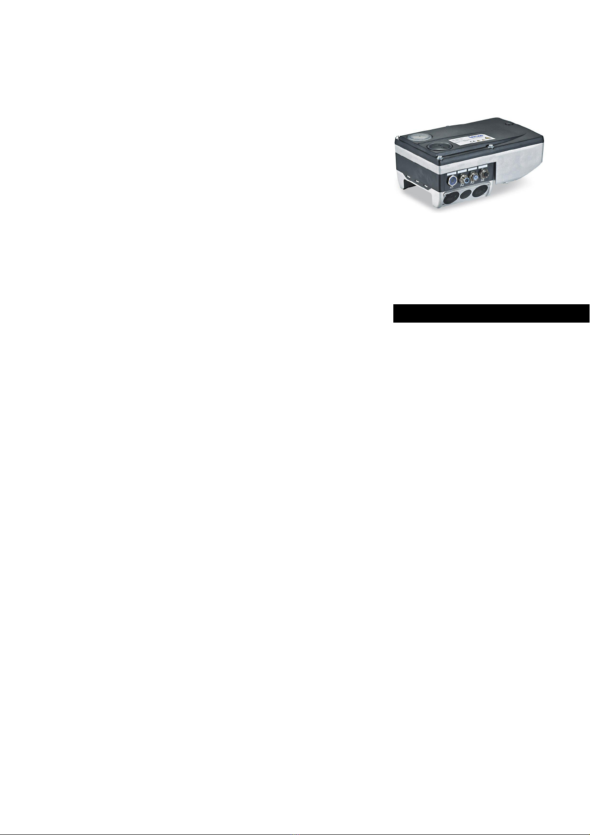
Inverter Drives 8400 motec_ _ _ _ _ _ _ _ _ _ _
E84DGxxxx...
Reference manual EN
Ä.Z>óä
13572994
L
Page 2

Overview of technical documentation for Inverter Drives 8400
_ _ _ _ _ _ _ _ _ _ _ _ _ _ _ _ _ _ _ _ _ _ _ _ _ _ _ _ _ _ _ _ _ _ _ _ _ _ _ _ _ _ _ _ _ _ _ _ _ _ _ _ _ _ _ _ _ _ _ _ _ _ _ _
Project planning, selection & ordering Legend:
8400 motec hardware manual Printed documentation
Catalogue Online documentation
(PDF/Engineer online help)
Mounting & wiring Abbreviations used:
MA 8400 motec BA Operating instructions
MA for the accessories KHB Communication manual
MA Mounting instructions
Parameter setting SW Software/reference manual
BA for diagnosis terminal
SW 8400 motec This documentation
KHB for communication unit
Drive commissioning
SW 8400 motec This documentation
chapter "Commissioning"
chapter "Diagnostics & error management"
Networking
KHB for communication unit
MA for the accessories
2 Lenze · 8400 motec · Reference manual · DMS 10.0 EN · 08/2019 · TD06
Page 3

Contents
Contents
_ _ _ _ _ _ _ _ _ _ _ _ _ _ _ _ _ _ _ _ _ _ _ _ _ _ _ _ _ _ _ _ _ _ _ _ _ _ _ _ _ _ _ _ _ _ _ _ _ _ _ _ _ _ _ _ _ _ _ _ _ _ _ _
1 About this documentation _ _ _ _ _ _ _ _ _ _ _ _ _ _ _ _ _ _ _ _ _ _ _ _ _ _ _ _ _ _ _ _ _ _ _ _ _ _ _ 12
1.1 Document history _ _ _ _ _ _ _ _ _ _ _ _ _ _ _ _ _ _ _ _ _ _ _ _ _ _ _ _ _ _ _ _ _ _ _ _ _ _ _ _ _ _ _ _ 13
1.2 Conventions used _ _ _ _ _ _ _ _ _ _ _ _ _ _ _ _ _ _ _ _ _ _ _ _ _ _ _ _ _ _ _ _ _ _ _ _ _ _ _ _ _ _ _ _ 14
1.3 Terminology used _ _ _ _ _ _ _ _ _ _ _ _ _ _ _ _ _ _ _ _ _ _ _ _ _ _ _ _ _ _ _ _ _ _ _ _ _ _ _ _ _ _ _ _ 15
1.4 Definition of the notes used _ _ _ _ _ _ _ _ _ _ _ _ _ _ _ _ _ _ _ _ _ _ _ _ _ _ _ _ _ _ _ _ _ _ _ _ _ _ 17
2 Introduction: Parameterising the inverter _ _ _ _ _ _ _ _ _ _ _ _ _ _ _ _ _ _ _ _ _ _ _ _ _ _ _ _ _ _ _ 19
2.1 Integrated technology applications _ _ _ _ _ _ _ _ _ _ _ _ _ _ _ _ _ _ _ _ _ _ _ _ _ _ _ _ _ _ _ _ _ _ 21
2.2 Selection of the appropriate commissioning tool _ _ _ _ _ _ _ _ _ _ _ _ _ _ _ _ _ _ _ _ _ _ _ _ _ _ _ 22
2.2.1 Overview: Accessories for commissioning _ _ _ _ _ _ _ _ _ _ _ _ _ _ _ _ _ _ _ _ _ _ _ _ _ _ 23
2.3 General notes on parameters _ _ _ _ _ _ _ _ _ _ _ _ _ _ _ _ _ _ _ _ _ _ _ _ _ _ _ _ _ _ _ _ _ _ _ _ _ _ 24
2.3.1 Changing the parameterisation with the keypad _ _ _ _ _ _ _ _ _ _ _ _ _ _ _ _ _ _ _ _ _ _ 25
2.3.2 Change parameter settings with PC and Lenze software _ _ _ _ _ _ _ _ _ _ _ _ _ _ _ _ _ _ 28
2.3.3 User menu for quick access to frequently used parameters _ _ _ _ _ _ _ _ _ _ _ _ _ _ _ _ _ 29
2.4 Handling the memory module _ _ _ _ _ _ _ _ _ _ _ _ _ _ _ _ _ _ _ _ _ _ _ _ _ _ _ _ _ _ _ _ _ _ _ _ _ 30
2.5 Device identification _ _ _ _ _ _ _ _ _ _ _ _ _ _ _ _ _ _ _ _ _ _ _ _ _ _ _ _ _ _ _ _ _ _ _ _ _ _ _ _ _ _ 32
2.5.1 Automatic acceptance of the device name in the »Engineer« _ _ _ _ _ _ _ _ _ _ _ _ _ _ _ _ 32
3 Commissioning _ _ _ _ _ _ _ _ _ _ _ _ _ _ _ _ _ _ _ _ _ _ _ _ _ _ _ _ _ _ _ _ _ _ _ _ _ _ _ _ _ _ _ _ _ 33
3.1 Safety instructions with regard to commissioning _ _ _ _ _ _ _ _ _ _ _ _ _ _ _ _ _ _ _ _ _ _ _ _ _ _ 34
3.2 Preconditions for commissioning with the »Engineer« _ _ _ _ _ _ _ _ _ _ _ _ _ _ _ _ _ _ _ _ _ _ _ _ 35
3.3 Trouble-shooting during commissioning _ _ _ _ _ _ _ _ _ _ _ _ _ _ _ _ _ _ _ _ _ _ _ _ _ _ _ _ _ _ _ 35
3.4 Commissioning wizard 8400 _ _ _ _ _ _ _ _ _ _ _ _ _ _ _ _ _ _ _ _ _ _ _ _ _ _ _ _ _ _ _ _ _ _ _ _ _ _ 36
3.5 Commissioning of the "Actuating drive speed" technology application _ _ _ _ _ _ _ _ _ _ _ _ _ _ _ 37
3.5.1 Prepare inverter for commissioning _ _ _ _ _ _ _ _ _ _ _ _ _ _ _ _ _ _ _ _ _ _ _ _ _ _ _ _ _ 38
3.5.2 Creating an »Engineer« project & going online _ _ _ _ _ _ _ _ _ _ _ _ _ _ _ _ _ _ _ _ _ _ _ 39
3.5.3 Parameterising the motor control _ _ _ _ _ _ _ _ _ _ _ _ _ _ _ _ _ _ _ _ _ _ _ _ _ _ _ _ _ _ 40
3.5.4 Parameterise application _ _ _ _ _ _ _ _ _ _ _ _ _ _ _ _ _ _ _ _ _ _ _ _ _ _ _ _ _ _ _ _ _ _ _ 42
3.5.5 Save parameter settings safe against mains failure _ _ _ _ _ _ _ _ _ _ _ _ _ _ _ _ _ _ _ _ _ 44
3.5.6 Enabling the inverter and selecting the speed _ _ _ _ _ _ _ _ _ _ _ _ _ _ _ _ _ _ _ _ _ _ _ _ 44
3.6 Commissioning of the "Switch-off positioning" technology application _ _ _ _ _ _ _ _ _ _ _ _ _ _ _ 45
3.6.1 Prepare inverter for commissioning _ _ _ _ _ _ _ _ _ _ _ _ _ _ _ _ _ _ _ _ _ _ _ _ _ _ _ _ _ 47
3.6.2 Creating an »Engineer« project & going online _ _ _ _ _ _ _ _ _ _ _ _ _ _ _ _ _ _ _ _ _ _ _ 48
3.6.3 Parameterising the motor control _ _ _ _ _ _ _ _ _ _ _ _ _ _ _ _ _ _ _ _ _ _ _ _ _ _ _ _ _ _ 49
3.6.4 Parameterise application _ _ _ _ _ _ _ _ _ _ _ _ _ _ _ _ _ _ _ _ _ _ _ _ _ _ _ _ _ _ _ _ _ _ _ 51
3.6.5 Save parameter settings safe against mains failure _ _ _ _ _ _ _ _ _ _ _ _ _ _ _ _ _ _ _ _ _ 53
3.6.6 Enable inverter and test application _ _ _ _ _ _ _ _ _ _ _ _ _ _ _ _ _ _ _ _ _ _ _ _ _ _ _ _ _ 53
3.7 PC manual control _ _ _ _ _ _ _ _ _ _ _ _ _ _ _ _ _ _ _ _ _ _ _ _ _ _ _ _ _ _ _ _ _ _ _ _ _ _ _ _ _ _ _ _ 54
3.8 Control via Field Package ("key-operated switch operation") _ _ _ _ _ _ _ _ _ _ _ _ _ _ _ _ _ _ _ _ _ 58
Lenze · 8400 motec · Reference manual · DMS 10.0 EN · 08/2019 · TD06 3
Page 4

Contents
_ _ _ _ _ _ _ _ _ _ _ _ _ _ _ _ _ _ _ _ _ _ _ _ _ _ _ _ _ _ _ _ _ _ _ _ _ _ _ _ _ _ _ _ _ _ _ _ _ _ _ _ _ _ _ _ _ _ _ _ _ _ _ _
4 Device control (DCTRL) _ _ _ _ _ _ _ _ _ _ _ _ _ _ _ _ _ _ _ _ _ _ _ _ _ _ _ _ _ _ _ _ _ _ _ _ _ _ _ _ _ 61
4.1 Device commands (C00002/x) _ _ _ _ _ _ _ _ _ _ _ _ _ _ _ _ _ _ _ _ _ _ _ _ _ _ _ _ _ _ _ _ _ _ _ _ _ 63
4.1.1 Load Lenze setting _ _ _ _ _ _ _ _ _ _ _ _ _ _ _ _ _ _ _ _ _ _ _ _ _ _ _ _ _ _ _ _ _ _ _ _ _ _ _ 65
4.1.2 Load parameter set 1 _ _ _ _ _ _ _ _ _ _ _ _ _ _ _ _ _ _ _ _ _ _ _ _ _ _ _ _ _ _ _ _ _ _ _ _ _ 66
4.1.3 Save parameter settings _ _ _ _ _ _ _ _ _ _ _ _ _ _ _ _ _ _ _ _ _ _ _ _ _ _ _ _ _ _ _ _ _ _ _ _ 67
4.1.4 Import EPM data _ _ _ _ _ _ _ _ _ _ _ _ _ _ _ _ _ _ _ _ _ _ _ _ _ _ _ _ _ _ _ _ _ _ _ _ _ _ _ _ 67
4.1.5 Enable/inhibit inverter _ _ _ _ _ _ _ _ _ _ _ _ _ _ _ _ _ _ _ _ _ _ _ _ _ _ _ _ _ _ _ _ _ _ _ _ _ 68
4.1.6 Activate/deactivate quick stop _ _ _ _ _ _ _ _ _ _ _ _ _ _ _ _ _ _ _ _ _ _ _ _ _ _ _ _ _ _ _ _ 68
4.1.7 Reset error _ _ _ _ _ _ _ _ _ _ _ _ _ _ _ _ _ _ _ _ _ _ _ _ _ _ _ _ _ _ _ _ _ _ _ _ _ _ _ _ _ _ _ 69
4.1.8 Delete logbook _ _ _ _ _ _ _ _ _ _ _ _ _ _ _ _ _ _ _ _ _ _ _ _ _ _ _ _ _ _ _ _ _ _ _ _ _ _ _ _ _ 69
4.1.9 Identify motor parameters _ _ _ _ _ _ _ _ _ _ _ _ _ _ _ _ _ _ _ _ _ _ _ _ _ _ _ _ _ _ _ _ _ _ 70
4.1.10 CAN reset node _ _ _ _ _ _ _ _ _ _ _ _ _ _ _ _ _ _ _ _ _ _ _ _ _ _ _ _ _ _ _ _ _ _ _ _ _ _ _ _ _ 70
4.1.11 Device search function _ _ _ _ _ _ _ _ _ _ _ _ _ _ _ _ _ _ _ _ _ _ _ _ _ _ _ _ _ _ _ _ _ _ _ _ _ 71
4.2 Device state machine and device states _ _ _ _ _ _ _ _ _ _ _ _ _ _ _ _ _ _ _ _ _ _ _ _ _ _ _ _ _ _ _ _ 72
4.2.1 Init _ _ _ _ _ _ _ _ _ _ _ _ _ _ _ _ _ _ _ _ _ _ _ _ _ _ _ _ _ _ _ _ _ _ _ _ _ _ _ _ _ _ _ _ _ _ _ 74
4.2.2 MotorIdent _ _ _ _ _ _ _ _ _ _ _ _ _ _ _ _ _ _ _ _ _ _ _ _ _ _ _ _ _ _ _ _ _ _ _ _ _ _ _ _ _ _ _ 75
4.2.3 SafeTorqueOff _ _ _ _ _ _ _ _ _ _ _ _ _ _ _ _ _ _ _ _ _ _ _ _ _ _ _ _ _ _ _ _ _ _ _ _ _ _ _ _ _ 75
4.2.4 ReadyToSwitchOn _ _ _ _ _ _ _ _ _ _ _ _ _ _ _ _ _ _ _ _ _ _ _ _ _ _ _ _ _ _ _ _ _ _ _ _ _ _ _ 76
4.2.5 SwitchedOn _ _ _ _ _ _ _ _ _ _ _ _ _ _ _ _ _ _ _ _ _ _ _ _ _ _ _ _ _ _ _ _ _ _ _ _ _ _ _ _ _ _ 77
4.2.6 OperationEnabled _ _ _ _ _ _ _ _ _ _ _ _ _ _ _ _ _ _ _ _ _ _ _ _ _ _ _ _ _ _ _ _ _ _ _ _ _ _ _ 78
4.2.7 Trouble _ _ _ _ _ _ _ _ _ _ _ _ _ _ _ _ _ _ _ _ _ _ _ _ _ _ _ _ _ _ _ _ _ _ _ _ _ _ _ _ _ _ _ _ _ 79
4.2.8 Fault _ _ _ _ _ _ _ _ _ _ _ _ _ _ _ _ _ _ _ _ _ _ _ _ _ _ _ _ _ _ _ _ _ _ _ _ _ _ _ _ _ _ _ _ _ _ 80
4.3 Auto-start option "Inhibit at power-on" _ _ _ _ _ _ _ _ _ _ _ _ _ _ _ _ _ _ _ _ _ _ _ _ _ _ _ _ _ _ _ _ 81
4.4 Energy saving mode _ _ _ _ _ _ _ _ _ _ _ _ _ _ _ _ _ _ _ _ _ _ _ _ _ _ _ _ _ _ _ _ _ _ _ _ _ _ _ _ _ _ _ 83
4 Lenze · 8400 motec · Reference manual · DMS 10.0 EN · 08/2019 · TD06
Page 5

Contents
_ _ _ _ _ _ _ _ _ _ _ _ _ _ _ _ _ _ _ _ _ _ _ _ _ _ _ _ _ _ _ _ _ _ _ _ _ _ _ _ _ _ _ _ _ _ _ _ _ _ _ _ _ _ _ _ _ _ _ _ _ _ _ _
5 Motor control (MCTRL) _ _ _ _ _ _ _ _ _ _ _ _ _ _ _ _ _ _ _ _ _ _ _ _ _ _ _ _ _ _ _ _ _ _ _ _ _ _ _ _ _ 85
5.1 Special features of the 8400 motec _ _ _ _ _ _ _ _ _ _ _ _ _ _ _ _ _ _ _ _ _ _ _ _ _ _ _ _ _ _ _ _ _ _ _ 86
5.2 Motor selection/Motor data _ _ _ _ _ _ _ _ _ _ _ _ _ _ _ _ _ _ _ _ _ _ _ _ _ _ _ _ _ _ _ _ _ _ _ _ _ _ 87
5.2.1 Selecting a motor from the motor catalogue in the »Engineer« _ _ _ _ _ _ _ _ _ _ _ _ _ _ 93
5.2.2 Automatic motor data identification _ _ _ _ _ _ _ _ _ _ _ _ _ _ _ _ _ _ _ _ _ _ _ _ _ _ _ _ _ 95
5.3 Selecting the control mode _ _ _ _ _ _ _ _ _ _ _ _ _ _ _ _ _ _ _ _ _ _ _ _ _ _ _ _ _ _ _ _ _ _ _ _ _ _ _ 97
5.3.1 Selection help _ _ _ _ _ _ _ _ _ _ _ _ _ _ _ _ _ _ _ _ _ _ _ _ _ _ _ _ _ _ _ _ _ _ _ _ _ _ _ _ _ 100
5.4 Defining current and speed limits _ _ _ _ _ _ _ _ _ _ _ _ _ _ _ _ _ _ _ _ _ _ _ _ _ _ _ _ _ _ _ _ _ _ _ 101
5.5 V/f characteristic control (VFCplus) _ _ _ _ _ _ _ _ _ _ _ _ _ _ _ _ _ _ _ _ _ _ _ _ _ _ _ _ _ _ _ _ _ _ _ 103
5.5.1 Parameterisation dialog/signal flow _ _ _ _ _ _ _ _ _ _ _ _ _ _ _ _ _ _ _ _ _ _ _ _ _ _ _ _ _ 103
5.5.2 Basic settings _ _ _ _ _ _ _ _ _ _ _ _ _ _ _ _ _ _ _ _ _ _ _ _ _ _ _ _ _ _ _ _ _ _ _ _ _ _ _ _ _ _ 105
5.5.2.1 Define V/f characteristic shape _ _ _ _ _ _ _ _ _ _ _ _ _ _ _ _ _ _ _ _ _ _ _ _ _ _ 105
5.5.2.2 Defining current limits (Imax controller) _ _ _ _ _ _ _ _ _ _ _ _ _ _ _ _ _ _ _ _ _ 106
5.5.3 Optimising the control mode _ _ _ _ _ _ _ _ _ _ _ _ _ _ _ _ _ _ _ _ _ _ _ _ _ _ _ _ _ _ _ _ _ 107
5.5.3.1 Adapting the V/f base frequency _ _ _ _ _ _ _ _ _ _ _ _ _ _ _ _ _ _ _ _ _ _ _ _ _ 108
5.5.3.2 Adapting the Vmin boost _ _ _ _ _ _ _ _ _ _ _ _ _ _ _ _ _ _ _ _ _ _ _ _ _ _ _ _ _ 109
5.5.3.3 Optimising the Imax controller _ _ _ _ _ _ _ _ _ _ _ _ _ _ _ _ _ _ _ _ _ _ _ _ _ _ 110
5.5.3.4 Torque limitation _ _ _ _ _ _ _ _ _ _ _ _ _ _ _ _ _ _ _ _ _ _ _ _ _ _ _ _ _ _ _ _ _ 111
5.5.3.5 Optimising the starting performance after a controller enable _ _ _ _ _ _ _ _ 112
5.5.4 Remedies for undesired drive behaviour _ _ _ _ _ _ _ _ _ _ _ _ _ _ _ _ _ _ _ _ _ _ _ _ _ _ _ 113
5.6 V/f characteristic control - energy-saving (VFCplusEco) _ _ _ _ _ _ _ _ _ _ _ _ _ _ _ _ _ _ _ _ _ _ _ _ 114
5.6.1 Parameterisation dialog/signal flow _ _ _ _ _ _ _ _ _ _ _ _ _ _ _ _ _ _ _ _ _ _ _ _ _ _ _ _ _ 115
5.6.2 Comparison of VFCplusEco - VFCplus _ _ _ _ _ _ _ _ _ _ _ _ _ _ _ _ _ _ _ _ _ _ _ _ _ _ _ _ _ 117
5.6.3 Basic settings _ _ _ _ _ _ _ _ _ _ _ _ _ _ _ _ _ _ _ _ _ _ _ _ _ _ _ _ _ _ _ _ _ _ _ _ _ _ _ _ _ _ 118
5.6.4 Optimising the control mode _ _ _ _ _ _ _ _ _ _ _ _ _ _ _ _ _ _ _ _ _ _ _ _ _ _ _ _ _ _ _ _ _ 119
5.6.4.1 Improving the behaviour at high dynamic load changes _ _ _ _ _ _ _ _ _ _ _ _ 120
5.6.4.2 Adapting the slope limitation for lowering the Eco function _ _ _ _ _ _ _ _ _ _ 120
5.6.4.3 Optimising the cos/phi controller _ _ _ _ _ _ _ _ _ _ _ _ _ _ _ _ _ _ _ _ _ _ _ _ 121
5.6.4.4 Optimising the starting performance after a controller enable _ _ _ _ _ _ _ _ 122
5.6.5 Remedies for undesired drive behaviour _ _ _ _ _ _ _ _ _ _ _ _ _ _ _ _ _ _ _ _ _ _ _ _ _ _ _ 123
5.7 V/f control (VFCplus + encoder) _ _ _ _ _ _ _ _ _ _ _ _ _ _ _ _ _ _ _ _ _ _ _ _ _ _ _ _ _ _ _ _ _ _ _ _ _ 124
5.7.1 Parameterisation dialog/signal flow _ _ _ _ _ _ _ _ _ _ _ _ _ _ _ _ _ _ _ _ _ _ _ _ _ _ _ _ _ 125
5.7.2 Basic settings _ _ _ _ _ _ _ _ _ _ _ _ _ _ _ _ _ _ _ _ _ _ _ _ _ _ _ _ _ _ _ _ _ _ _ _ _ _ _ _ _ _ 127
5.7.2.1 Define V/f characteristic shape _ _ _ _ _ _ _ _ _ _ _ _ _ _ _ _ _ _ _ _ _ _ _ _ _ _ 128
5.7.2.2 Defining current limits (Imax controller) _ _ _ _ _ _ _ _ _ _ _ _ _ _ _ _ _ _ _ _ _ 129
5.7.2.3 Parameterising the slip regulator _ _ _ _ _ _ _ _ _ _ _ _ _ _ _ _ _ _ _ _ _ _ _ _ _ 130
5.7.3 Optimising the control mode _ _ _ _ _ _ _ _ _ _ _ _ _ _ _ _ _ _ _ _ _ _ _ _ _ _ _ _ _ _ _ _ _ 134
5.7.3.1 Optimising the starting performance after a controller enable _ _ _ _ _ _ _ _ 134
5.8 Sensorless vector control (SLVC) _ _ _ _ _ _ _ _ _ _ _ _ _ _ _ _ _ _ _ _ _ _ _ _ _ _ _ _ _ _ _ _ _ _ _ _ 135
5.8.1 Parameterisation dialog _ _ _ _ _ _ _ _ _ _ _ _ _ _ _ _ _ _ _ _ _ _ _ _ _ _ _ _ _ _ _ _ _ _ _ _ 136
5.8.2 Types of control _ _ _ _ _ _ _ _ _ _ _ _ _ _ _ _ _ _ _ _ _ _ _ _ _ _ _ _ _ _ _ _ _ _ _ _ _ _ _ _ 137
5.8.2.1 Speed control with torque limitation _ _ _ _ _ _ _ _ _ _ _ _ _ _ _ _ _ _ _ _ _ _ 138
5.8.2.2 Torque control with speed limitation _ _ _ _ _ _ _ _ _ _ _ _ _ _ _ _ _ _ _ _ _ _ 139
5.8.3 Basic settings _ _ _ _ _ _ _ _ _ _ _ _ _ _ _ _ _ _ _ _ _ _ _ _ _ _ _ _ _ _ _ _ _ _ _ _ _ _ _ _ _ _ 141
5.8.3.1 Reduction of the speed overshoot _ _ _ _ _ _ _ _ _ _ _ _ _ _ _ _ _ _ _ _ _ _ _ _ 142
5.8.4 Optimising the control mode _ _ _ _ _ _ _ _ _ _ _ _ _ _ _ _ _ _ _ _ _ _ _ _ _ _ _ _ _ _ _ _ _ 143
5.8.4.1 Optimising the starting performance after a controller enable _ _ _ _ _ _ _ _ 143
5.8.5 Remedies for undesired drive behaviour _ _ _ _ _ _ _ _ _ _ _ _ _ _ _ _ _ _ _ _ _ _ _ _ _ _ _ 144
Lenze · 8400 motec · Reference manual · DMS 10.0 EN · 08/2019 · TD06 5
Page 6

Contents
_ _ _ _ _ _ _ _ _ _ _ _ _ _ _ _ _ _ _ _ _ _ _ _ _ _ _ _ _ _ _ _ _ _ _ _ _ _ _ _ _ _ _ _ _ _ _ _ _ _ _ _ _ _ _ _ _ _ _ _ _ _ _ _
5.9 Sensorless control for synchronous motors (SLPSM) _ _ _ _ _ _ _ _ _ _ _ _ _ _ _ _ _ _ _ _ _ _ _ _ _ 145
5.9.1 Parameterisation dialog/signal flow _ _ _ _ _ _ _ _ _ _ _ _ _ _ _ _ _ _ _ _ _ _ _ _ _ _ _ _ _ 148
5.9.2 Increasing the acceleration of the drive _ _ _ _ _ _ _ _ _ _ _ _ _ _ _ _ _ _ _ _ _ _ _ _ _ _ _ 151
5.9.3 Types of control _ _ _ _ _ _ _ _ _ _ _ _ _ _ _ _ _ _ _ _ _ _ _ _ _ _ _ _ _ _ _ _ _ _ _ _ _ _ _ _ 151
5.9.4 Basic settings _ _ _ _ _ _ _ _ _ _ _ _ _ _ _ _ _ _ _ _ _ _ _ _ _ _ _ _ _ _ _ _ _ _ _ _ _ _ _ _ _ _ 153
5.9.5 Optimising the control mode _ _ _ _ _ _ _ _ _ _ _ _ _ _ _ _ _ _ _ _ _ _ _ _ _ _ _ _ _ _ _ _ _ 154
5.9.5.1 Optimise current controller _ _ _ _ _ _ _ _ _ _ _ _ _ _ _ _ _ _ _ _ _ _ _ _ _ _ _ _ 155
5.9.5.2 Optimise speed controller _ _ _ _ _ _ _ _ _ _ _ _ _ _ _ _ _ _ _ _ _ _ _ _ _ _ _ _ _ 155
5.9.5.3 Current-dependent stator leakage inductance Ppp(I) _ _ _ _ _ _ _ _ _ _ _ _ _ _ 159
5.9.5.4 Optimising the starting performance after a controller enable _ _ _ _ _ _ _ _ 161
5.9.6 Pole position identification without motion _ _ _ _ _ _ _ _ _ _ _ _ _ _ _ _ _ _ _ _ _ _ _ _ _ 162
5.9.7 Field weakening for synchronous motors _ _ _ _ _ _ _ _ _ _ _ _ _ _ _ _ _ _ _ _ _ _ _ _ _ _ 164
5.10 Parameterisable additional functions _ _ _ _ _ _ _ _ _ _ _ _ _ _ _ _ _ _ _ _ _ _ _ _ _ _ _ _ _ _ _ _ _ 168
5.10.1 Selection of switching frequency _ _ _ _ _ _ _ _ _ _ _ _ _ _ _ _ _ _ _ _ _ _ _ _ _ _ _ _ _ _ _ 168
5.10.2 Flying restart function _ _ _ _ _ _ _ _ _ _ _ _ _ _ _ _ _ _ _ _ _ _ _ _ _ _ _ _ _ _ _ _ _ _ _ _ _ 171
5.10.3 DC-injection braking _ _ _ _ _ _ _ _ _ _ _ _ _ _ _ _ _ _ _ _ _ _ _ _ _ _ _ _ _ _ _ _ _ _ _ _ _ _ 173
5.10.3.1 Manual DC-injection braking (DCB) _ _ _ _ _ _ _ _ _ _ _ _ _ _ _ _ _ _ _ _ _ _ _ 174
5.10.3.2 Automatic DC-injection braking (auto DCB) _ _ _ _ _ _ _ _ _ _ _ _ _ _ _ _ _ _ _ 174
5.10.4 Slip compensation _ _ _ _ _ _ _ _ _ _ _ _ _ _ _ _ _ _ _ _ _ _ _ _ _ _ _ _ _ _ _ _ _ _ _ _ _ _ _ 177
5.10.5 Oscillation damping _ _ _ _ _ _ _ _ _ _ _ _ _ _ _ _ _ _ _ _ _ _ _ _ _ _ _ _ _ _ _ _ _ _ _ _ _ _ 178
5.10.6 Mass inertia precontrol _ _ _ _ _ _ _ _ _ _ _ _ _ _ _ _ _ _ _ _ _ _ _ _ _ _ _ _ _ _ _ _ _ _ _ _ 179
5.11 Encoder/feedback system _ _ _ _ _ _ _ _ _ _ _ _ _ _ _ _ _ _ _ _ _ _ _ _ _ _ _ _ _ _ _ _ _ _ _ _ _ _ _ _ 181
5.11.1 Encoder evaluation method _ _ _ _ _ _ _ _ _ _ _ _ _ _ _ _ _ _ _ _ _ _ _ _ _ _ _ _ _ _ _ _ _ _ 184
5.12 Braking operation/brake energy management _ _ _ _ _ _ _ _ _ _ _ _ _ _ _ _ _ _ _ _ _ _ _ _ _ _ _ _ 186
5.12.1 Settings for mountable brake resistors _ _ _ _ _ _ _ _ _ _ _ _ _ _ _ _ _ _ _ _ _ _ _ _ _ _ _ _ 186
5.12.2 Settings for internal brake resistor _ _ _ _ _ _ _ _ _ _ _ _ _ _ _ _ _ _ _ _ _ _ _ _ _ _ _ _ _ _ 188
5.12.3 Voltage limits for braking operation _ _ _ _ _ _ _ _ _ _ _ _ _ _ _ _ _ _ _ _ _ _ _ _ _ _ _ _ _ 188
5.12.4 Response to an increase of the DC-bus voltage _ _ _ _ _ _ _ _ _ _ _ _ _ _ _ _ _ _ _ _ _ _ _ 188
5.12.4.1 Inverter motor brake _ _ _ _ _ _ _ _ _ _ _ _ _ _ _ _ _ _ _ _ _ _ _ _ _ _ _ _ _ _ _ 190
5.12.4.2 Degradation of braking energy by motor overmagnetisation _ _ _ _ _ _ _ _ _ 193
5.13 Power and energy display _ _ _ _ _ _ _ _ _ _ _ _ _ _ _ _ _ _ _ _ _ _ _ _ _ _ _ _ _ _ _ _ _ _ _ _ _ _ _ _ 194
5.14 Monitoring _ _ _ _ _ _ _ _ _ _ _ _ _ _ _ _ _ _ _ _ _ _ _ _ _ _ _ _ _ _ _ _ _ _ _ _ _ _ _ _ _ _ _ _ _ _ _ _ 195
5.14.1 Device overload monitoring (Ixt) _ _ _ _ _ _ _ _ _ _ _ _ _ _ _ _ _ _ _ _ _ _ _ _ _ _ _ _ _ _ _ 196
5.14.2 Motor load monitoring (I2xt) _ _ _ _ _ _ _ _ _ _ _ _ _ _ _ _ _ _ _ _ _ _ _ _ _ _ _ _ _ _ _ _ _ 197
5.14.3 Motor temperature monitoring (PTC) _ _ _ _ _ _ _ _ _ _ _ _ _ _ _ _ _ _ _ _ _ _ _ _ _ _ _ _ 200
5.14.4 Brake resistor monitoring (I2xt) _ _ _ _ _ _ _ _ _ _ _ _ _ _ _ _ _ _ _ _ _ _ _ _ _ _ _ _ _ _ _ _ 201
5.14.5 Mains phase failure monitoring _ _ _ _ _ _ _ _ _ _ _ _ _ _ _ _ _ _ _ _ _ _ _ _ _ _ _ _ _ _ _ _ 203
5.14.6 Maximum current monitoring _ _ _ _ _ _ _ _ _ _ _ _ _ _ _ _ _ _ _ _ _ _ _ _ _ _ _ _ _ _ _ _ 203
5.14.7 Current monitoring for overload _ _ _ _ _ _ _ _ _ _ _ _ _ _ _ _ _ _ _ _ _ _ _ _ _ _ _ _ _ _ _ 204
5.14.8 Motor speed monitoring _ _ _ _ _ _ _ _ _ _ _ _ _ _ _ _ _ _ _ _ _ _ _ _ _ _ _ _ _ _ _ _ _ _ _ _ 205
5.14.9 Encoder open-circuit monitoring _ _ _ _ _ _ _ _ _ _ _ _ _ _ _ _ _ _ _ _ _ _ _ _ _ _ _ _ _ _ _ 205
6I/O terminals _ _ _ _ _ _ _ _ _ _ _ _ _ _ _ _ _ _ _ _ _ _ _ _ _ _ _ _ _ _ _ _ _ _ _ _ _ _ _ _ _ _ _ _ _ _ _ 206
6.1 Digital terminals _ _ _ _ _ _ _ _ _ _ _ _ _ _ _ _ _ _ _ _ _ _ _ _ _ _ _ _ _ _ _ _ _ _ _ _ _ _ _ _ _ _ _ _ _ 207
6.1.1 Configuring DI1 and DI2 as frequency inputs _ _ _ _ _ _ _ _ _ _ _ _ _ _ _ _ _ _ _ _ _ _ _ _ 211
6.2 Analog terminals _ _ _ _ _ _ _ _ _ _ _ _ _ _ _ _ _ _ _ _ _ _ _ _ _ _ _ _ _ _ _ _ _ _ _ _ _ _ _ _ _ _ _ _ 214
6.2.1 Parameterising analog input _ _ _ _ _ _ _ _ _ _ _ _ _ _ _ _ _ _ _ _ _ _ _ _ _ _ _ _ _ _ _ _ _ 215
6.3 User-defined terminal assignment _ _ _ _ _ _ _ _ _ _ _ _ _ _ _ _ _ _ _ _ _ _ _ _ _ _ _ _ _ _ _ _ _ _ _ 217
6.3.1 Source-destination principle _ _ _ _ _ _ _ _ _ _ _ _ _ _ _ _ _ _ _ _ _ _ _ _ _ _ _ _ _ _ _ _ _ 218
6.3.2 Changing the terminal assignment with the »Engineer« _ _ _ _ _ _ _ _ _ _ _ _ _ _ _ _ _ _ 219
6.3.3 Changing the terminal assignment via configuration parameters _ _ _ _ _ _ _ _ _ _ _ _ _ 220
6.4 Electrical data _ _ _ _ _ _ _ _ _ _ _ _ _ _ _ _ _ _ _ _ _ _ _ _ _ _ _ _ _ _ _ _ _ _ _ _ _ _ _ _ _ _ _ _ _ _ 223
6 Lenze · 8400 motec · Reference manual · DMS 10.0 EN · 08/2019 · TD06
Page 7

Contents
_ _ _ _ _ _ _ _ _ _ _ _ _ _ _ _ _ _ _ _ _ _ _ _ _ _ _ _ _ _ _ _ _ _ _ _ _ _ _ _ _ _ _ _ _ _ _ _ _ _ _ _ _ _ _ _ _ _ _ _ _ _ _ _
7 Technology applications _ _ _ _ _ _ _ _ _ _ _ _ _ _ _ _ _ _ _ _ _ _ _ _ _ _ _ _ _ _ _ _ _ _ _ _ _ _ _ _ 225
7.1 Selection of the technology application and the control mode _ _ _ _ _ _ _ _ _ _ _ _ _ _ _ _ _ _ _ _ 226
7.2 TA "Actuating drive speed" _ _ _ _ _ _ _ _ _ _ _ _ _ _ _ _ _ _ _ _ _ _ _ _ _ _ _ _ _ _ _ _ _ _ _ _ _ _ _ 227
7.2.1 Basic signal flow _ _ _ _ _ _ _ _ _ _ _ _ _ _ _ _ _ _ _ _ _ _ _ _ _ _ _ _ _ _ _ _ _ _ _ _ _ _ _ _ 228
7.2.1.1 "GeneralPurpose" functions _ _ _ _ _ _ _ _ _ _ _ _ _ _ _ _ _ _ _ _ _ _ _ _ _ _ _ 231
7.2.2 Interface description _ _ _ _ _ _ _ _ _ _ _ _ _ _ _ _ _ _ _ _ _ _ _ _ _ _ _ _ _ _ _ _ _ _ _ _ _ _ 232
7.2.2.1 wDriveControl control word _ _ _ _ _ _ _ _ _ _ _ _ _ _ _ _ _ _ _ _ _ _ _ _ _ _ _ 238
7.2.2.2 Status word _ _ _ _ _ _ _ _ _ _ _ _ _ _ _ _ _ _ _ _ _ _ _ _ _ _ _ _ _ _ _ _ _ _ _ _ 238
7.2.3 Terminal assignment of the control modes _ _ _ _ _ _ _ _ _ _ _ _ _ _ _ _ _ _ _ _ _ _ _ _ _ 240
7.2.3.1 Terminals 0 _ _ _ _ _ _ _ _ _ _ _ _ _ _ _ _ _ _ _ _ _ _ _ _ _ _ _ _ _ _ _ _ _ _ _ _ 241
7.2.3.2 Terminals 2 _ _ _ _ _ _ _ _ _ _ _ _ _ _ _ _ _ _ _ _ _ _ _ _ _ _ _ _ _ _ _ _ _ _ _ _ 242
7.2.3.3 Terminals 11 _ _ _ _ _ _ _ _ _ _ _ _ _ _ _ _ _ _ _ _ _ _ _ _ _ _ _ _ _ _ _ _ _ _ _ _ 242
7.2.3.4 Terminal 16 _ _ _ _ _ _ _ _ _ _ _ _ _ _ _ _ _ _ _ _ _ _ _ _ _ _ _ _ _ _ _ _ _ _ _ _ 243
7.2.3.5 Network (MCI/CAN) _ _ _ _ _ _ _ _ _ _ _ _ _ _ _ _ _ _ _ _ _ _ _ _ _ _ _ _ _ _ _ _ 243
7.2.3.6 Network (AS-i) _ _ _ _ _ _ _ _ _ _ _ _ _ _ _ _ _ _ _ _ _ _ _ _ _ _ _ _ _ _ _ _ _ _ _ 245
7.2.4 Setting parameters (short overview) _ _ _ _ _ _ _ _ _ _ _ _ _ _ _ _ _ _ _ _ _ _ _ _ _ _ _ _ _ 246
7.2.5 Pre-assignment of the application _ _ _ _ _ _ _ _ _ _ _ _ _ _ _ _ _ _ _ _ _ _ _ _ _ _ _ _ _ _ 247
7.2.5.1 Input connections _ _ _ _ _ _ _ _ _ _ _ _ _ _ _ _ _ _ _ _ _ _ _ _ _ _ _ _ _ _ _ _ _ 247
7.2.5.2 Output connections _ _ _ _ _ _ _ _ _ _ _ _ _ _ _ _ _ _ _ _ _ _ _ _ _ _ _ _ _ _ _ _ 250
7.2.5.3 Internal signal flow for control via terminals _ _ _ _ _ _ _ _ _ _ _ _ _ _ _ _ _ _ 252
7.2.5.4 Internal signal flow for control via network (MCI/CAN) _ _ _ _ _ _ _ _ _ _ _ _ _ 253
7.2.5.5 Internal signal flow for control via network (AS-i) _ _ _ _ _ _ _ _ _ _ _ _ _ _ _ _ 254
7.3 TA "Actuating drive speed (AC Drive Profile)" _ _ _ _ _ _ _ _ _ _ _ _ _ _ _ _ _ _ _ _ _ _ _ _ _ _ _ _ _ 256
7.3.1 Basic signal flow _ _ _ _ _ _ _ _ _ _ _ _ _ _ _ _ _ _ _ _ _ _ _ _ _ _ _ _ _ _ _ _ _ _ _ _ _ _ _ _ 257
7.3.2 Scaling of the speed and torque values (Ref from Net) _ _ _ _ _ _ _ _ _ _ _ _ _ _ _ _ _ _ _ 259
7.3.3 Interface description _ _ _ _ _ _ _ _ _ _ _ _ _ _ _ _ _ _ _ _ _ _ _ _ _ _ _ _ _ _ _ _ _ _ _ _ _ _ 261
7.3.3.1 "AC Drive Profile" control word _ _ _ _ _ _ _ _ _ _ _ _ _ _ _ _ _ _ _ _ _ _ _ _ _ _ 261
7.3.3.2 "AC Drive Profile" status word _ _ _ _ _ _ _ _ _ _ _ _ _ _ _ _ _ _ _ _ _ _ _ _ _ _ 262
7.3.4 Setting parameters (short overview) _ _ _ _ _ _ _ _ _ _ _ _ _ _ _ _ _ _ _ _ _ _ _ _ _ _ _ _ _ 262
7.3.5 Internal signal flow _ _ _ _ _ _ _ _ _ _ _ _ _ _ _ _ _ _ _ _ _ _ _ _ _ _ _ _ _ _ _ _ _ _ _ _ _ _ 263
7.4 TA "Switch-off positioning" _ _ _ _ _ _ _ _ _ _ _ _ _ _ _ _ _ _ _ _ _ _ _ _ _ _ _ _ _ _ _ _ _ _ _ _ _ _ _ 265
7.4.1 Functional principle _ _ _ _ _ _ _ _ _ _ _ _ _ _ _ _ _ _ _ _ _ _ _ _ _ _ _ _ _ _ _ _ _ _ _ _ _ _ 267
7.4.2 Basic signal flow _ _ _ _ _ _ _ _ _ _ _ _ _ _ _ _ _ _ _ _ _ _ _ _ _ _ _ _ _ _ _ _ _ _ _ _ _ _ _ _ 269
7.4.3 Interface description _ _ _ _ _ _ _ _ _ _ _ _ _ _ _ _ _ _ _ _ _ _ _ _ _ _ _ _ _ _ _ _ _ _ _ _ _ _ 271
7.4.3.1 wDriveControl control word _ _ _ _ _ _ _ _ _ _ _ _ _ _ _ _ _ _ _ _ _ _ _ _ _ _ _ 271
7.4.3.2 wDeviceStateWord status word _ _ _ _ _ _ _ _ _ _ _ _ _ _ _ _ _ _ _ _ _ _ _ _ _ 272
7.4.4 Terminal assignment of the control modes _ _ _ _ _ _ _ _ _ _ _ _ _ _ _ _ _ _ _ _ _ _ _ _ _ 273
7.4.4.1 Terminals 0 _ _ _ _ _ _ _ _ _ _ _ _ _ _ _ _ _ _ _ _ _ _ _ _ _ _ _ _ _ _ _ _ _ _ _ _ 274
7.4.4.2 Terminals 2 _ _ _ _ _ _ _ _ _ _ _ _ _ _ _ _ _ _ _ _ _ _ _ _ _ _ _ _ _ _ _ _ _ _ _ _ 275
7.4.4.3 Terminals 11 _ _ _ _ _ _ _ _ _ _ _ _ _ _ _ _ _ _ _ _ _ _ _ _ _ _ _ _ _ _ _ _ _ _ _ _ 276
7.4.4.4 Terminal 16 _ _ _ _ _ _ _ _ _ _ _ _ _ _ _ _ _ _ _ _ _ _ _ _ _ _ _ _ _ _ _ _ _ _ _ _ 277
7.4.4.5 Network (MCI/CAN) _ _ _ _ _ _ _ _ _ _ _ _ _ _ _ _ _ _ _ _ _ _ _ _ _ _ _ _ _ _ _ _ 278
7.4.4.6 Network (AS-i) _ _ _ _ _ _ _ _ _ _ _ _ _ _ _ _ _ _ _ _ _ _ _ _ _ _ _ _ _ _ _ _ _ _ _ 279
7.4.5 Setting parameters (short overview) _ _ _ _ _ _ _ _ _ _ _ _ _ _ _ _ _ _ _ _ _ _ _ _ _ _ _ _ _ 280
7.4.6 Pre-assignment of the application _ _ _ _ _ _ _ _ _ _ _ _ _ _ _ _ _ _ _ _ _ _ _ _ _ _ _ _ _ _ 281
7.4.6.1 Input connections _ _ _ _ _ _ _ _ _ _ _ _ _ _ _ _ _ _ _ _ _ _ _ _ _ _ _ _ _ _ _ _ _ 281
7.4.6.2 Output connections _ _ _ _ _ _ _ _ _ _ _ _ _ _ _ _ _ _ _ _ _ _ _ _ _ _ _ _ _ _ _ _ 284
7.4.6.3 Internal signal flow for control via terminals _ _ _ _ _ _ _ _ _ _ _ _ _ _ _ _ _ _ 286
7.4.6.4 Internal signal flow for control via network (MCI/CAN) _ _ _ _ _ _ _ _ _ _ _ _ _ 287
7.4.6.5 Internal signal flow for control via network (AS-i) _ _ _ _ _ _ _ _ _ _ _ _ _ _ _ _ 288
Lenze · 8400 motec · Reference manual · DMS 10.0 EN · 08/2019 · TD06 7
Page 8

Contents
_ _ _ _ _ _ _ _ _ _ _ _ _ _ _ _ _ _ _ _ _ _ _ _ _ _ _ _ _ _ _ _ _ _ _ _ _ _ _ _ _ _ _ _ _ _ _ _ _ _ _ _ _ _ _ _ _ _ _ _ _ _ _ _
8Basic functions _ _ _ _ _ _ _ _ _ _ _ _ _ _ _ _ _ _ _ _ _ _ _ _ _ _ _ _ _ _ _ _ _ _ _ _ _ _ _ _ _ _ _ _ _ _ 289
8.1 Parameter change-over _ _ _ _ _ _ _ _ _ _ _ _ _ _ _ _ _ _ _ _ _ _ _ _ _ _ _ _ _ _ _ _ _ _ _ _ _ _ _ _ _ 290
8.1.1 Configuring the list using the »Engineer« parameterisation dialog _ _ _ _ _ _ _ _ _ _ _ _ 290
8.1.2 Configuring the list by means of parameterisation _ _ _ _ _ _ _ _ _ _ _ _ _ _ _ _ _ _ _ _ _ 293
8.1.3 Selecting a value set _ _ _ _ _ _ _ _ _ _ _ _ _ _ _ _ _ _ _ _ _ _ _ _ _ _ _ _ _ _ _ _ _ _ _ _ _ _ 294
8.1.4 Activating the writing of the parameters _ _ _ _ _ _ _ _ _ _ _ _ _ _ _ _ _ _ _ _ _ _ _ _ _ _ _ 294
8.2 Holding brake control _ _ _ _ _ _ _ _ _ _ _ _ _ _ _ _ _ _ _ _ _ _ _ _ _ _ _ _ _ _ _ _ _ _ _ _ _ _ _ _ _ _ 295
8.2.1 Parameter setting _ _ _ _ _ _ _ _ _ _ _ _ _ _ _ _ _ _ _ _ _ _ _ _ _ _ _ _ _ _ _ _ _ _ _ _ _ _ _ 296
8.2.1.1 Functional changes from firmware version 05.00.00 _ _ _ _ _ _ _ _ _ _ _ _ _ _ 298
8.2.1.2 Functional changes from firmware version 07.00.00 _ _ _ _ _ _ _ _ _ _ _ _ _ _ 298
8.2.1.3 Functional changes from firmware version 09.00.00 onwards _ _ _ _ _ _ _ _ _ 299
8.2.1.4 Operating mode _ _ _ _ _ _ _ _ _ _ _ _ _ _ _ _ _ _ _ _ _ _ _ _ _ _ _ _ _ _ _ _ _ _ 299
8.2.1.5 Functional settings _ _ _ _ _ _ _ _ _ _ _ _ _ _ _ _ _ _ _ _ _ _ _ _ _ _ _ _ _ _ _ _ 301
8.2.1.6 Switching thresholds _ _ _ _ _ _ _ _ _ _ _ _ _ _ _ _ _ _ _ _ _ _ _ _ _ _ _ _ _ _ _ 302
8.2.1.7 Application and release time _ _ _ _ _ _ _ _ _ _ _ _ _ _ _ _ _ _ _ _ _ _ _ _ _ _ _ 304
8.2.1.8 Motor magnetising time (only with asynchronous motor) _ _ _ _ _ _ _ _ _ _ _ 306
8.2.1.9 Actual value monitoring _ _ _ _ _ _ _ _ _ _ _ _ _ _ _ _ _ _ _ _ _ _ _ _ _ _ _ _ _ 306
8.2.2 Process when brake is released _ _ _ _ _ _ _ _ _ _ _ _ _ _ _ _ _ _ _ _ _ _ _ _ _ _ _ _ _ _ _ _ 307
8.2.3 Process when brake is closed _ _ _ _ _ _ _ _ _ _ _ _ _ _ _ _ _ _ _ _ _ _ _ _ _ _ _ _ _ _ _ _ _ 308
8.2.4 Behaviour in case of pulse inhibit _ _ _ _ _ _ _ _ _ _ _ _ _ _ _ _ _ _ _ _ _ _ _ _ _ _ _ _ _ _ _ 310
8.2.5 Feedforward control of the motor before release _ _ _ _ _ _ _ _ _ _ _ _ _ _ _ _ _ _ _ _ _ _ 311
8 Lenze · 8400 motec · Reference manual · DMS 10.0 EN · 08/2019 · TD06
Page 9

Contents
_ _ _ _ _ _ _ _ _ _ _ _ _ _ _ _ _ _ _ _ _ _ _ _ _ _ _ _ _ _ _ _ _ _ _ _ _ _ _ _ _ _ _ _ _ _ _ _ _ _ _ _ _ _ _ _ _ _ _ _ _ _ _ _
9 Diagnostics & error management _ _ _ _ _ _ _ _ _ _ _ _ _ _ _ _ _ _ _ _ _ _ _ _ _ _ _ _ _ _ _ _ _ _ _ 312
9.1 Basics on error handling in the inverter _ _ _ _ _ _ _ _ _ _ _ _ _ _ _ _ _ _ _ _ _ _ _ _ _ _ _ _ _ _ _ _ 312
9.2 LED status display _ _ _ _ _ _ _ _ _ _ _ _ _ _ _ _ _ _ _ _ _ _ _ _ _ _ _ _ _ _ _ _ _ _ _ _ _ _ _ _ _ _ _ _ 313
9.3 Drive diagnostics with the »Engineer« _ _ _ _ _ _ _ _ _ _ _ _ _ _ _ _ _ _ _ _ _ _ _ _ _ _ _ _ _ _ _ _ _ 314
9.3.1 Display details of the current error _ _ _ _ _ _ _ _ _ _ _ _ _ _ _ _ _ _ _ _ _ _ _ _ _ _ _ _ _ _ 316
9.3.2 Display of DIP switch positions _ _ _ _ _ _ _ _ _ _ _ _ _ _ _ _ _ _ _ _ _ _ _ _ _ _ _ _ _ _ _ _ 317
9.3.2.1 DIP switch / potentiometer assignment 0 _ _ _ _ _ _ _ _ _ _ _ _ _ _ _ _ _ _ _ _ 318
9.3.2.2 DIP switch / potentiometer assignment 1 _ _ _ _ _ _ _ _ _ _ _ _ _ _ _ _ _ _ _ _ 320
9.4 Drive diagnostics via bus system _ _ _ _ _ _ _ _ _ _ _ _ _ _ _ _ _ _ _ _ _ _ _ _ _ _ _ _ _ _ _ _ _ _ _ _ 322
9.5 Logbook _ _ _ _ _ _ _ _ _ _ _ _ _ _ _ _ _ _ _ _ _ _ _ _ _ _ _ _ _ _ _ _ _ _ _ _ _ _ _ _ _ _ _ _ _ _ _ _ _ 323
9.5.1 Functional description _ _ _ _ _ _ _ _ _ _ _ _ _ _ _ _ _ _ _ _ _ _ _ _ _ _ _ _ _ _ _ _ _ _ _ _ _ 323
9.5.2 Reading out logbook entries _ _ _ _ _ _ _ _ _ _ _ _ _ _ _ _ _ _ _ _ _ _ _ _ _ _ _ _ _ _ _ _ _ _ 324
9.5.3 Exporting logbook entries to a file _ _ _ _ _ _ _ _ _ _ _ _ _ _ _ _ _ _ _ _ _ _ _ _ _ _ _ _ _ _ 324
9.6 Monitoring _ _ _ _ _ _ _ _ _ _ _ _ _ _ _ _ _ _ _ _ _ _ _ _ _ _ _ _ _ _ _ _ _ _ _ _ _ _ _ _ _ _ _ _ _ _ _ _ 325
9.6.1 Monitoring configuration _ _ _ _ _ _ _ _ _ _ _ _ _ _ _ _ _ _ _ _ _ _ _ _ _ _ _ _ _ _ _ _ _ _ _ 326
9.6.2 Setting the error response _ _ _ _ _ _ _ _ _ _ _ _ _ _ _ _ _ _ _ _ _ _ _ _ _ _ _ _ _ _ _ _ _ _ _ 327
9.7 Maloperation of the drive _ _ _ _ _ _ _ _ _ _ _ _ _ _ _ _ _ _ _ _ _ _ _ _ _ _ _ _ _ _ _ _ _ _ _ _ _ _ _ _ 328
9.8 Error messages of the operating system _ _ _ _ _ _ _ _ _ _ _ _ _ _ _ _ _ _ _ _ _ _ _ _ _ _ _ _ _ _ _ _ 331
9.8.1 Structure of the 32-bit error number (bit coding) _ _ _ _ _ _ _ _ _ _ _ _ _ _ _ _ _ _ _ _ _ _ 331
9.8.1.1 Error type _ _ _ _ _ _ _ _ _ _ _ _ _ _ _ _ _ _ _ _ _ _ _ _ _ _ _ _ _ _ _ _ _ _ _ _ _ _ 331
9.8.1.2 Error subject area _ _ _ _ _ _ _ _ _ _ _ _ _ _ _ _ _ _ _ _ _ _ _ _ _ _ _ _ _ _ _ _ _ 332
9.8.1.3 Error ID _ _ _ _ _ _ _ _ _ _ _ _ _ _ _ _ _ _ _ _ _ _ _ _ _ _ _ _ _ _ _ _ _ _ _ _ _ _ _ 332
9.8.1.4 Example for bit coding of the error number _ _ _ _ _ _ _ _ _ _ _ _ _ _ _ _ _ _ _ 333
9.8.2 Structure of the 16 bit error number (bit coding) _ _ _ _ _ _ _ _ _ _ _ _ _ _ _ _ _ _ _ _ _ _ 334
9.8.3 Reset error message _ _ _ _ _ _ _ _ _ _ _ _ _ _ _ _ _ _ _ _ _ _ _ _ _ _ _ _ _ _ _ _ _ _ _ _ _ _ 335
9.8.4 Short overview (A-Z) _ _ _ _ _ _ _ _ _ _ _ _ _ _ _ _ _ _ _ _ _ _ _ _ _ _ _ _ _ _ _ _ _ _ _ _ _ _ 336
9.8.5 Cause & possible remedies _ _ _ _ _ _ _ _ _ _ _ _ _ _ _ _ _ _ _ _ _ _ _ _ _ _ _ _ _ _ _ _ _ _ 338
10 Communication _ _ _ _ _ _ _ _ _ _ _ _ _ _ _ _ _ _ _ _ _ _ _ _ _ _ _ _ _ _ _ _ _ _ _ _ _ _ _ _ _ _ _ _ _ 352
10.1 General information _ _ _ _ _ _ _ _ _ _ _ _ _ _ _ _ _ _ _ _ _ _ _ _ _ _ _ _ _ _ _ _ _ _ _ _ _ _ _ _ _ _ _ 352
10.2 Selection of the communication in the »Engineer« _ _ _ _ _ _ _ _ _ _ _ _ _ _ _ _ _ _ _ _ _ _ _ _ _ _ 353
10.3 Control mode "Network (MCI/CAN)" _ _ _ _ _ _ _ _ _ _ _ _ _ _ _ _ _ _ _ _ _ _ _ _ _ _ _ _ _ _ _ _ _ _ 354
10.3.1 Pre-assignment of the data words _ _ _ _ _ _ _ _ _ _ _ _ _ _ _ _ _ _ _ _ _ _ _ _ _ _ _ _ _ _ 355
10.3.2 Port block "LP_Network_In" _ _ _ _ _ _ _ _ _ _ _ _ _ _ _ _ _ _ _ _ _ _ _ _ _ _ _ _ _ _ _ _ _ _ 356
10.3.3 Port block "LP_Network_Out" _ _ _ _ _ _ _ _ _ _ _ _ _ _ _ _ _ _ _ _ _ _ _ _ _ _ _ _ _ _ _ _ _ 357
11 Parameter reference _ _ _ _ _ _ _ _ _ _ _ _ _ _ _ _ _ _ _ _ _ _ _ _ _ _ _ _ _ _ _ _ _ _ _ _ _ _ _ _ _ _ _ 358
11.1 Structure of the parameter descriptions _ _ _ _ _ _ _ _ _ _ _ _ _ _ _ _ _ _ _ _ _ _ _ _ _ _ _ _ _ _ _ _ 359
11.1.1 Data type _ _ _ _ _ _ _ _ _ _ _ _ _ _ _ _ _ _ _ _ _ _ _ _ _ _ _ _ _ _ _ _ _ _ _ _ _ _ _ _ _ _ _ _ 360
11.1.2 Parameters with read-only access _ _ _ _ _ _ _ _ _ _ _ _ _ _ _ _ _ _ _ _ _ _ _ _ _ _ _ _ _ _ 360
11.1.3 Parameters with write access _ _ _ _ _ _ _ _ _ _ _ _ _ _ _ _ _ _ _ _ _ _ _ _ _ _ _ _ _ _ _ _ _ 361
11.1.3.1 Parameters with setting range _ _ _ _ _ _ _ _ _ _ _ _ _ _ _ _ _ _ _ _ _ _ _ _ _ _ 361
11.1.3.2 Parameters with selection list _ _ _ _ _ _ _ _ _ _ _ _ _ _ _ _ _ _ _ _ _ _ _ _ _ _ 361
11.1.3.3 Parameters with bit-coded setting _ _ _ _ _ _ _ _ _ _ _ _ _ _ _ _ _ _ _ _ _ _ _ _ 362
11.1.3.4 Parameters with subcodes _ _ _ _ _ _ _ _ _ _ _ _ _ _ _ _ _ _ _ _ _ _ _ _ _ _ _ _ 363
11.1.4 Parameter attributes _ _ _ _ _ _ _ _ _ _ _ _ _ _ _ _ _ _ _ _ _ _ _ _ _ _ _ _ _ _ _ _ _ _ _ _ _ _ 364
11.2 Parameter list _ _ _ _ _ _ _ _ _ _ _ _ _ _ _ _ _ _ _ _ _ _ _ _ _ _ _ _ _ _ _ _ _ _ _ _ _ _ _ _ _ _ _ _ _ _ 365
11.3 Selection list - analog signals _ _ _ _ _ _ _ _ _ _ _ _ _ _ _ _ _ _ _ _ _ _ _ _ _ _ _ _ _ _ _ _ _ _ _ _ _ _ 475
11.4 Selection list - digital signals _ _ _ _ _ _ _ _ _ _ _ _ _ _ _ _ _ _ _ _ _ _ _ _ _ _ _ _ _ _ _ _ _ _ _ _ _ _ 477
11.5 Table of attributes _ _ _ _ _ _ _ _ _ _ _ _ _ _ _ _ _ _ _ _ _ _ _ _ _ _ _ _ _ _ _ _ _ _ _ _ _ _ _ _ _ _ _ _ 480
Lenze · 8400 motec · Reference manual · DMS 10.0 EN · 08/2019 · TD06 9
Page 10

Contents
_ _ _ _ _ _ _ _ _ _ _ _ _ _ _ _ _ _ _ _ _ _ _ _ _ _ _ _ _ _ _ _ _ _ _ _ _ _ _ _ _ _ _ _ _ _ _ _ _ _ _ _ _ _ _ _ _ _ _ _ _ _ _ _
12 Function library _ _ _ _ _ _ _ _ _ _ _ _ _ _ _ _ _ _ _ _ _ _ _ _ _ _ _ _ _ _ _ _ _ _ _ _ _ _ _ _ _ _ _ _ _ 487
12.1 L_MPot_1 _ _ _ _ _ _ _ _ _ _ _ _ _ _ _ _ _ _ _ _ _ _ _ _ _ _ _ _ _ _ _ _ _ _ _ _ _ _ _ _ _ _ _ _ _ _ _ _ 488
12.1.1 Activate & control motor potentiometer _ _ _ _ _ _ _ _ _ _ _ _ _ _ _ _ _ _ _ _ _ _ _ _ _ _ _ 490
12.1.2 Deactivate motor potentiometer _ _ _ _ _ _ _ _ _ _ _ _ _ _ _ _ _ _ _ _ _ _ _ _ _ _ _ _ _ _ _ 491
12.2 L_NSet_1 _ _ _ _ _ _ _ _ _ _ _ _ _ _ _ _ _ _ _ _ _ _ _ _ _ _ _ _ _ _ _ _ _ _ _ _ _ _ _ _ _ _ _ _ _ _ _ _ _ 492
12.2.1 Main setpoint path _ _ _ _ _ _ _ _ _ _ _ _ _ _ _ _ _ _ _ _ _ _ _ _ _ _ _ _ _ _ _ _ _ _ _ _ _ _ _ 494
12.2.2 JOG setpoints _ _ _ _ _ _ _ _ _ _ _ _ _ _ _ _ _ _ _ _ _ _ _ _ _ _ _ _ _ _ _ _ _ _ _ _ _ _ _ _ _ _ 494
12.2.3 Setpoint inversion _ _ _ _ _ _ _ _ _ _ _ _ _ _ _ _ _ _ _ _ _ _ _ _ _ _ _ _ _ _ _ _ _ _ _ _ _ _ _ 494
12.2.4 Skip frequency function _ _ _ _ _ _ _ _ _ _ _ _ _ _ _ _ _ _ _ _ _ _ _ _ _ _ _ _ _ _ _ _ _ _ _ _ 495
12.2.5 Ramp function generator for the main setpoint _ _ _ _ _ _ _ _ _ _ _ _ _ _ _ _ _ _ _ _ _ _ _ 498
12.2.6 S-ramp _ _ _ _ _ _ _ _ _ _ _ _ _ _ _ _ _ _ _ _ _ _ _ _ _ _ _ _ _ _ _ _ _ _ _ _ _ _ _ _ _ _ _ _ _ 498
12.3 L_PCTRL_1 _ _ _ _ _ _ _ _ _ _ _ _ _ _ _ _ _ _ _ _ _ _ _ _ _ _ _ _ _ _ _ _ _ _ _ _ _ _ _ _ _ _ _ _ _ _ _ _ 499
12.3.1 Control characteristic _ _ _ _ _ _ _ _ _ _ _ _ _ _ _ _ _ _ _ _ _ _ _ _ _ _ _ _ _ _ _ _ _ _ _ _ _ 503
12.3.2 Ramp function generator _ _ _ _ _ _ _ _ _ _ _ _ _ _ _ _ _ _ _ _ _ _ _ _ _ _ _ _ _ _ _ _ _ _ _ 504
12.3.3 Operating range of the PID process controller _ _ _ _ _ _ _ _ _ _ _ _ _ _ _ _ _ _ _ _ _ _ _ _ 504
12.3.4 Evaluation of the output signal _ _ _ _ _ _ _ _ _ _ _ _ _ _ _ _ _ _ _ _ _ _ _ _ _ _ _ _ _ _ _ _ 504
12.3.5 Control functions _ _ _ _ _ _ _ _ _ _ _ _ _ _ _ _ _ _ _ _ _ _ _ _ _ _ _ _ _ _ _ _ _ _ _ _ _ _ _ 505
12.4 L_RLQ_1 _ _ _ _ _ _ _ _ _ _ _ _ _ _ _ _ _ _ _ _ _ _ _ _ _ _ _ _ _ _ _ _ _ _ _ _ _ _ _ _ _ _ _ _ _ _ _ _ _ 506
12.5 L_Compare_1 _ _ _ _ _ _ _ _ _ _ _ _ _ _ _ _ _ _ _ _ _ _ _ _ _ _ _ _ _ _ _ _ _ _ _ _ _ _ _ _ _ _ _ _ _ _ 508
12.5.1 Function 1: nIn1 = nIn2 _ _ _ _ _ _ _ _ _ _ _ _ _ _ _ _ _ _ _ _ _ _ _ _ _ _ _ _ _ _ _ _ _ _ _ _ 509
12.5.2 Function 2: nIn1 > nIn2 _ _ _ _ _ _ _ _ _ _ _ _ _ _ _ _ _ _ _ _ _ _ _ _ _ _ _ _ _ _ _ _ _ _ _ _ 510
12.5.3 Function 3: nIn1 < nIn2 _ _ _ _ _ _ _ _ _ _ _ _ _ _ _ _ _ _ _ _ _ _ _ _ _ _ _ _ _ _ _ _ _ _ _ _ 511
12.5.4 Function 4: |nIn1| = |nIn2| _ _ _ _ _ _ _ _ _ _ _ _ _ _ _ _ _ _ _ _ _ _ _ _ _ _ _ _ _ _ _ _ _ _ _ 512
12.5.5 Function 5: |nIn1| > |nIn2| _ _ _ _ _ _ _ _ _ _ _ _ _ _ _ _ _ _ _ _ _ _ _ _ _ _ _ _ _ _ _ _ _ _ _ 512
12.5.6 Function 6: |nIn1| < |nIn2| _ _ _ _ _ _ _ _ _ _ _ _ _ _ _ _ _ _ _ _ _ _ _ _ _ _ _ _ _ _ _ _ _ _ _ 512
12.6 L_Counter_1 _ _ _ _ _ _ _ _ _ _ _ _ _ _ _ _ _ _ _ _ _ _ _ _ _ _ _ _ _ _ _ _ _ _ _ _ _ _ _ _ _ _ _ _ _ _ _ 513
12.7 L_DigitalDelay_1 _ _ _ _ _ _ _ _ _ _ _ _ _ _ _ _ _ _ _ _ _ _ _ _ _ _ _ _ _ _ _ _ _ _ _ _ _ _ _ _ _ _ _ _ 515
12.7.1 Application example: Debouncing a digital input _ _ _ _ _ _ _ _ _ _ _ _ _ _ _ _ _ _ _ _ _ _ 517
12.8 L_DigitalDelay_2 _ _ _ _ _ _ _ _ _ _ _ _ _ _ _ _ _ _ _ _ _ _ _ _ _ _ _ _ _ _ _ _ _ _ _ _ _ _ _ _ _ _ _ _ 518
12.9 L_DigitalLogic_1 _ _ _ _ _ _ _ _ _ _ _ _ _ _ _ _ _ _ _ _ _ _ _ _ _ _ _ _ _ _ _ _ _ _ _ _ _ _ _ _ _ _ _ _ _ 519
12.10 L_DigitalLogic_2 _ _ _ _ _ _ _ _ _ _ _ _ _ _ _ _ _ _ _ _ _ _ _ _ _ _ _ _ _ _ _ _ _ _ _ _ _ _ _ _ _ _ _ _ _ 521
12.11 L_JogCtrlExtension_1 _ _ _ _ _ _ _ _ _ _ _ _ _ _ _ _ _ _ _ _ _ _ _ _ _ _ _ _ _ _ _ _ _ _ _ _ _ _ _ _ _ _ 523
12.12 LS_AnalogInput _ _ _ _ _ _ _ _ _ _ _ _ _ _ _ _ _ _ _ _ _ _ _ _ _ _ _ _ _ _ _ _ _ _ _ _ _ _ _ _ _ _ _ _ _ 526
12.13 LS_Convert_1 _ _ _ _ _ _ _ _ _ _ _ _ _ _ _ _ _ _ _ _ _ _ _ _ _ _ _ _ _ _ _ _ _ _ _ _ _ _ _ _ _ _ _ _ _ _ 527
12.13.1 Conversion formulae _ _ _ _ _ _ _ _ _ _ _ _ _ _ _ _ _ _ _ _ _ _ _ _ _ _ _ _ _ _ _ _ _ _ _ _ _ _ 528
12.13.2 Function 19: Counting and providing external encoder pulses _ _ _ _ _ _ _ _ _ _ _ _ _ _ _ 529
12.14 LS_Convert_2 _ _ _ _ _ _ _ _ _ _ _ _ _ _ _ _ _ _ _ _ _ _ _ _ _ _ _ _ _ _ _ _ _ _ _ _ _ _ _ _ _ _ _ _ _ _ 530
12.14.1 Conversion formulae _ _ _ _ _ _ _ _ _ _ _ _ _ _ _ _ _ _ _ _ _ _ _ _ _ _ _ _ _ _ _ _ _ _ _ _ _ _ 531
12.15 LS_Convert_3 _ _ _ _ _ _ _ _ _ _ _ _ _ _ _ _ _ _ _ _ _ _ _ _ _ _ _ _ _ _ _ _ _ _ _ _ _ _ _ _ _ _ _ _ _ _ 532
12.15.1 Conversion formulae _ _ _ _ _ _ _ _ _ _ _ _ _ _ _ _ _ _ _ _ _ _ _ _ _ _ _ _ _ _ _ _ _ _ _ _ _ _ 533
12.16 LS_DigitalInput _ _ _ _ _ _ _ _ _ _ _ _ _ _ _ _ _ _ _ _ _ _ _ _ _ _ _ _ _ _ _ _ _ _ _ _ _ _ _ _ _ _ _ _ _ 534
12.17 LS_DigitalOutput _ _ _ _ _ _ _ _ _ _ _ _ _ _ _ _ _ _ _ _ _ _ _ _ _ _ _ _ _ _ _ _ _ _ _ _ _ _ _ _ _ _ _ _ 535
12.18 LS_DisFree _ _ _ _ _ _ _ _ _ _ _ _ _ _ _ _ _ _ _ _ _ _ _ _ _ _ _ _ _ _ _ _ _ _ _ _ _ _ _ _ _ _ _ _ _ _ _ _ 536
12.19 LS_DisFree_a _ _ _ _ _ _ _ _ _ _ _ _ _ _ _ _ _ _ _ _ _ _ _ _ _ _ _ _ _ _ _ _ _ _ _ _ _ _ _ _ _ _ _ _ _ _ _ 537
12.20 LS_DisFree_b _ _ _ _ _ _ _ _ _ _ _ _ _ _ _ _ _ _ _ _ _ _ _ _ _ _ _ _ _ _ _ _ _ _ _ _ _ _ _ _ _ _ _ _ _ _ _ 538
12.21 LS_DriveInterface _ _ _ _ _ _ _ _ _ _ _ _ _ _ _ _ _ _ _ _ _ _ _ _ _ _ _ _ _ _ _ _ _ _ _ _ _ _ _ _ _ _ _ _ 539
12.22 LS_ParFix _ _ _ _ _ _ _ _ _ _ _ _ _ _ _ _ _ _ _ _ _ _ _ _ _ _ _ _ _ _ _ _ _ _ _ _ _ _ _ _ _ _ _ _ _ _ _ _ _ 542
12.23 LS_ParFree _ _ _ _ _ _ _ _ _ _ _ _ _ _ _ _ _ _ _ _ _ _ _ _ _ _ _ _ _ _ _ _ _ _ _ _ _ _ _ _ _ _ _ _ _ _ _ _ 543
12.24 LS_ParFree_a _ _ _ _ _ _ _ _ _ _ _ _ _ _ _ _ _ _ _ _ _ _ _ _ _ _ _ _ _ _ _ _ _ _ _ _ _ _ _ _ _ _ _ _ _ _ _ 544
12.25 LS_ParFree_b _ _ _ _ _ _ _ _ _ _ _ _ _ _ _ _ _ _ _ _ _ _ _ _ _ _ _ _ _ _ _ _ _ _ _ _ _ _ _ _ _ _ _ _ _ _ _ 545
12.26 LS_SetError_1 _ _ _ _ _ _ _ _ _ _ _ _ _ _ _ _ _ _ _ _ _ _ _ _ _ _ _ _ _ _ _ _ _ _ _ _ _ _ _ _ _ _ _ _ _ _ 546
12.27 LS_ParReadWrite_1 _ _ _ _ _ _ _ _ _ _ _ _ _ _ _ _ _ _ _ _ _ _ _ _ _ _ _ _ _ _ _ _ _ _ _ _ _ _ _ _ _ _ _ 547
12.28 LS_WriteParamList _ _ _ _ _ _ _ _ _ _ _ _ _ _ _ _ _ _ _ _ _ _ _ _ _ _ _ _ _ _ _ _ _ _ _ _ _ _ _ _ _ _ _ 549
10 Lenze · 8400 motec · Reference manual · DMS 10.0 EN · 08/2019 · TD06
Page 11

Contents
_ _ _ _ _ _ _ _ _ _ _ _ _ _ _ _ _ _ _ _ _ _ _ _ _ _ _ _ _ _ _ _ _ _ _ _ _ _ _ _ _ _ _ _ _ _ _ _ _ _ _ _ _ _ _ _ _ _ _ _ _ _ _ _
13 Application examples _ _ _ _ _ _ _ _ _ _ _ _ _ _ _ _ _ _ _ _ _ _ _ _ _ _ _ _ _ _ _ _ _ _ _ _ _ _ _ _ _ _ 550
13.1 Sequence control _ _ _ _ _ _ _ _ _ _ _ _ _ _ _ _ _ _ _ _ _ _ _ _ _ _ _ _ _ _ _ _ _ _ _ _ _ _ _ _ _ _ _ _ 550
13.2 Delayed disconnection in partial-load operation ("Sleep Mode") _ _ _ _ _ _ _ _ _ _ _ _ _ _ _ _ _ _ _ 553
13.3 Motor load test _ _ _ _ _ _ _ _ _ _ _ _ _ _ _ _ _ _ _ _ _ _ _ _ _ _ _ _ _ _ _ _ _ _ _ _ _ _ _ _ _ _ _ _ _ 555
Index _ _ _ _ _ _ _ _ _ _ _ _ _ _ _ _ _ _ _ _ _ _ _ _ _ _ _ _ _ _ _ _ _ _ _ _ _ _ _ _ _ _ _ _ _ _ _ _ _ _ _ 556
Your opinion is important to us _ _ _ _ _ _ _ _ _ _ _ _ _ _ _ _ _ _ _ _ _ _ _ _ _ _ _ _ _ _ _ _ _ _ _ _ _ 566
Lenze · 8400 motec · Reference manual · DMS 10.0 EN · 08/2019 · TD06 11
Page 12

1 About this documentation
_ _ _ _ _ _ _ _ _ _ _ _ _ _ _ _ _ _ _ _ _ _ _ _ _ _ _ _ _ _ _ _ _ _ _ _ _ _ _ _ _ _ _ _ _ _ _ _ _ _ _ _ _ _ _ _ _ _ _ _ _ _ _ _
1 About this documentation
Danger!
The inverter is a source of danger which may lead to death or the severe injury of
persons.
To protect yourself and others against these dangers, observe the safety instructions
before switching on the inverter.
Please read the safety instructions in the mounting instructions and the hardware
manual for the 8400 motec inverter. Both documents are supplied with the inverter.
This software manual contains information regarding the parameterisation of the 8400 motec
inverter by means of the L-force »Engineer«.
The information in this software manual applies to the 8400 motec inverter with the following
nameplate data:
Product range Type designation From software version
8400 motec E84DGDVBxxxxxxx 01.00
All screenshots provided in this documentation are application examples. Depending on the
software version of the inverter and the version of the »Engineer« software installed, the
screenshots in this documentation may differ from the representation in the »Engineer«.
Tip!
Information and tools regarding the Lenze products can be found on the Internet:
http://www.lenze.com
Download
12 Lenze · 8400 motec · Reference manual · DMS 10.0 EN · 08/2019 · TD06
Page 13

1 About this documentation
1.1 Document history
_ _ _ _ _ _ _ _ _ _ _ _ _ _ _ _ _ _ _ _ _ _ _ _ _ _ _ _ _ _ _ _ _ _ _ _ _ _ _ _ _ _ _ _ _ _ _ _ _ _ _ _ _ _ _ _ _ _ _ _ _ _ _ _
1.1 Document history
Version Description
10.0 08/2019 TD06 Error corrections & supplements for 8400 motec (FW11.01.00)
9.0 09/2018 TD23 Extension to POWERLINK
8.1 02/2018 TD23 Error corrections & supplements
8.0 01/2018 TD23 Extended by new functions for 8400 motec V10.00.00, error corrections
7.0 06/2017 TD23 Extended by new functions for 8400 motec V09.00.00, error corrections
6.0 12/2014 TD06 Extended by new functions for 8400 motec V07.00.00
5.0 09/2014 TD05 Extended by new functions for 8400 motec V06.01.00
4.1 08/2013 TD05 Corrections
4.0 07/2013 TD05 Extended by new functions for 8400 motec V05.00.00
3.0 09/2012 TD05 • Extended by new functions for 8400 motec V03.00.00, V03.01.00, V04.00.00
2.0 02/2011 TD05 • Extended by new functions for 8400 motec V02.00.00
1.2 10/2010 TD05 Corrections
1.1 05/2010 TD05 Corrections
1.0 04/2010 TD05 First edition
and V04.01.00
• Changed to new layout
• Extended by chapter "Application examples"
Lenze · 8400 motec · Reference manual · DMS 10.0 EN · 08/2019 · TD06 13
Page 14
1 About this documentation
1.2 Conventions used
_ _ _ _ _ _ _ _ _ _ _ _ _ _ _ _ _ _ _ _ _ _ _ _ _ _ _ _ _ _ _ _ _ _ _ _ _ _ _ _ _ _ _ _ _ _ _ _ _ _ _ _ _ _ _ _ _ _ _ _ _ _ _ _
1.2 Conventions used
This Software Manual uses the following conventions to distinguish between different types of
information:
Type of information Highlighting Examples/notes
Numeric notation
Decimal separator Point The decimal point is always used.
For example: 1234.56
Text
Version information Blue text colour All information that only applies to or from a certain
Program name » « The Lenze »Engineer« PC software...
Window italics The Message window... / The dialog box Options...
Variable names By setting bEnable to TRUE...
Control element Bold The OK button... / The Copy command... / The Properties
Sequence of menu
commands
Shortcut <bold> Use <F1> to open the online help.
Hyperlink Underlined
Symbols
Page reference ( 14) Optically highlighted reference to another page. It is
Step-by-step instructions
software version of the inverter is marked accordingly in this
documentation.
Example: This function extension is available from software
version V3.0!
tab... / The Name input field...
If several commands must be used in sequence to carry out a
function, the individual commands are separated by an
arrow: Select File
If a shortcut is required for a command to be executed, a "+"
has been put between the key identifiers: With
<Shift>+<ESC> ...
Optically highlighted reference to another topic. It is
activated with a mouse-click in this online documentation.
activated with a mouse-click in this online documentation.
Step-by-step instructions are indicated by a pictograph.
Open to...
14
All information that only applies to or from a certain software version of the inverter is marked
accordingly in this documentation.
Lenze · 8400 motec · Reference manual · DMS 10.0 EN · 08/2019 · TD06
Page 15
1 About this documentation
1.3 Terminology used
_ _ _ _ _ _ _ _ _ _ _ _ _ _ _ _ _ _ _ _ _ _ _ _ _ _ _ _ _ _ _ _ _ _ _ _ _ _ _ _ _ _ _ _ _ _ _ _ _ _ _ _ _ _ _ _ _ _ _ _ _ _ _ _
1.3 Terminology used
Term Meaning
Drive Unit
Communication unit
Wiring Unit
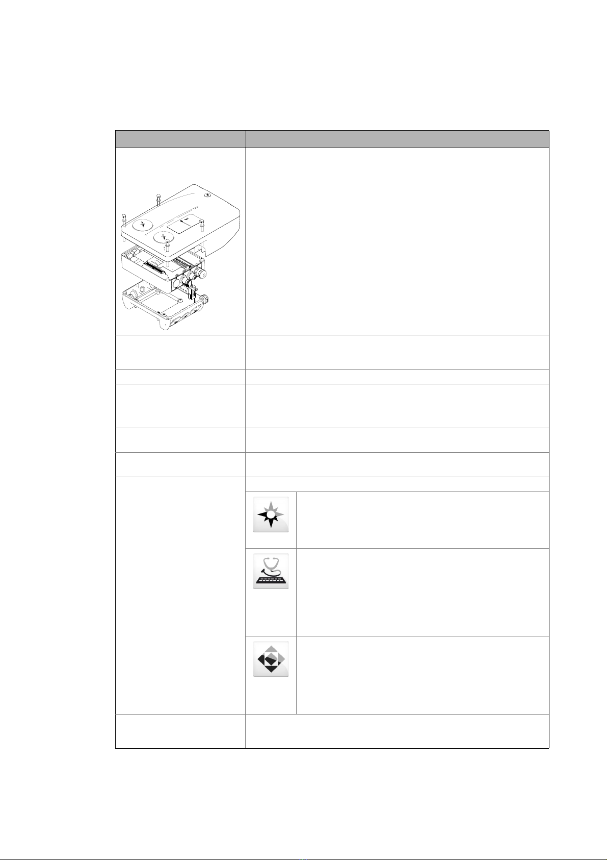
The 8400 motec inverter has a modular structure that includes the following
modules: "Drive Unit", "Communication Unit", and "Wiring Unit".
• The drive unit is available in different power settings.
• In case of the communication unit you can select between:
• Without fieldbus (basic I/O, standard I/O, extended I/O)
• AS interface (without safety/with safety STO)
• CANopen (without safety/with safety STO)
• EtherCAT (without safety/with safety STO)
• EtherNET/IP (without safety/with safety STO)
• PROFIBUS (without safety/with safety STO)
• PROFINET (without safety/with safety STO)
• POWERLINK (without safety/with safety STO)
• The wiring unit provides flexible connection possibilities for a simple
integration into the power supply of the machine.
Application A technology application is a drive solution equipped with Lenze's experience
and know-how in which function and system blocks interconnected to a signal
flow are the basis for implementing typical drive tasks.
ASM Async. motor
Service brake The service brake serves to shutdown rotary or translatory masses in motion in
a controlled manner. The energy to be dissipated in this process is converted into
heat in the form of friction energy. This process is a regular and recurring
operating mode.
Code Parameter which serves to parameterise and monitor the inverter. In normal
usage, the term is usually referred to as "Index".
Display code Parameter that displays the current status or value of an input/output of a
system block.
Engineering tools Software solutions for easy engineering in all project stages
»EASY Navigator« – ensures easy operator guidance
• All convenient Lenze engineering tools at a glance
• Tools can be quickly selected
• The clear structure simplifies the engineering process from the
start
»EASY Starter« – easy-to-use tool for service technicians
• Specifically designed for commissioning and maintaining Lenze
devices
• Graphic user interface with very few icons
• Easy to run online diagnostics, set parameters and perform
commissioning
• No risk of accidentally changing an application
• Loading off-the-shelf applications onto the device
»Engineer« – multi-device engineering
• For all products in our L-force portfolio
• Practical user interface
• Graphic interfaces make it easy to navigate
• Can be applied in every phase of a project (project planning,
commissioning, production)
• Parameter setting and configuration
EPM Memory module on which all parametes of the drive system are saved non-
volatilely. These include the parameters of the inverter and communicationrelevant parameters for the communication unit used.
Lenze · 8400 motec · Reference manual · DMS 10.0 EN · 08/2019 · TD06 15
Page 16

1 About this documentation
1.3 Terminology used
_ _ _ _ _ _ _ _ _ _ _ _ _ _ _ _ _ _ _ _ _ _ _ _ _ _ _ _ _ _ _ _ _ _ _ _ _ _ _ _ _ _ _ _ _ _ _ _ _ _ _ _ _ _ _ _ _ _ _ _ _ _ _ _
Term Meaning
Function block A function block can be compared with an integrated circuit that contains a
DC injection brake The DC injection brake is to brake and/or hold the motor. For this purpose, the
Holding brake The holding brake serves to hold the rotor by means of a mechanical unit.
Diagnosis terminal / keypad The diagnosis terminal combines the keypad with a housing and a connecting
LA Abbreviation: Lenze Application block
Lenze setting This setting is the default factory setting of the device.
LP Abbreviation: Lenze Port block
LS Abbreviation: Lenze System block
Port block Block for implementing the process data transfer via a fieldbus
QSP Quickstop
SLVC Motor control: Sensorless vector control ("SensorLess Vector Control")
Subcode If a code contains several parameters, they are stored in "subcodes".
System block In the application, system blocks provide interfaces to basic functions and to the
USB diagnostic adapter The USB diagnostic adapter is used for the operation, parameterisation, and
VFCplus Motor control: V/f characteristic control ("Voltage Frequency
VFCplusEco Motor control: V/f characteristic control - energy-saving
certain control logic and delivers one or several values when being executed.
• Each function block has a unique identifier, e.g. "L_MPot_1" (motor
potentiometer function)
8400 motec creates a quasi DC field at the stator of the asynchronous machine.
The energy to be dissipated is converted into heat in the rotor.
cable. The diagnosis terminal serves to check or change individual settings. In a
quick commissioning menu, the inverter can be parameterised in the basic
settings by means of the diagnosis terminal.
Note: If this documentation contains descriptions of settings with the keypad,
use the diagnosis terminal instead for the 8400 motec, since the keypad cannot
directly be plugged into the diagnostic interface of the 8400 motec.
• Example: "LA_NCtrl" – block for the "actuating drive speed" application.
• Example: "LP_Network_In" – port block for fieldbus communication.
• Example: "LS_DigitalInput" – system block for digital input signals.
This Manual uses a slash "/" as a separator between code and subcode
(e.g. "C00039/1").
This term is also referred to as "subindex" in common parlance.
hardware of the inverter (e.g. to the digital inputs).
diagnostics of the inverter. Data are exchanged between the PC (USB
connection) and the inverter (diagnostic interface on the front) via the
diagnostic adapter.
• Order designation: E94AZCUS
Control")
In this motor control mode, the inverter adapts the motor voltage to the
requirements of the load. Especially at speeds lower than 50 % of the rated
speed and a reduced torque, losses in the motor and in the inverter can be
reduced. Hence, the usually bad efficiency of the drive in the partial load
operational range is significantly increased.
16
Lenze · 8400 motec · Reference manual · DMS 10.0 EN · 08/2019 · TD06
Page 17

1 About this documentation
1.4 Definition of the notes used
_ _ _ _ _ _ _ _ _ _ _ _ _ _ _ _ _ _ _ _ _ _ _ _ _ _ _ _ _ _ _ _ _ _ _ _ _ _ _ _ _ _ _ _ _ _ _ _ _ _ _ _ _ _ _ _ _ _ _ _ _ _ _ _
1.4 Definition of the notes used
The following signal words and symbols are used in this Software Manual to indicate dangers and
important information:
Safety instructions
Structure of the safety instructions:
Pictograph and signal word!
(characterise the type and severity of danger)
Note
(describes the danger and gives information about how to prevent dangerous
situations)
Pictograph Signal word Meaning
Danger! Danger of personal injury through dangerous electrical voltage
Danger! Danger of personal injury through a general source of danger
Stop! Danger of damage to material assets
Application notes
Pictograph Signal word Meaning
Note! Important note to ensure trouble-free operation
Reference to an imminent danger that may result in d eath or se riou s per sonal injury
if the corresponding measures are not taken.
Reference to an imminent danger that may result in d eath or se riou s per sonal injury
if the corresponding measures are not taken.
Reference to a possible danger that may result in property damage if the
corresponding measures are not taken.
Tip! Useful tip for easy handling
Lenze · 8400 motec · Reference manual · DMS 10.0 EN · 08/2019 · TD06 17
Page 18

1 About this documentation
1.4 Definition of the notes used
_ _ _ _ _ _ _ _ _ _ _ _ _ _ _ _ _ _ _ _ _ _ _ _ _ _ _ _ _ _ _ _ _ _ _ _ _ _ _ _ _ _ _ _ _ _ _ _ _ _ _ _ _ _ _ _ _ _ _ _ _ _ _ _
This page has been left blank intentionally,
to present the following information more clearly.
18
Lenze · 8400 motec · Reference manual · DMS 10.0 EN · 08/2019 · TD06
Page 19

2 Introduction: Parameterising the inverter
_ _ _ _ _ _ _ _ _ _ _ _ _ _ _ _ _ _ _ _ _ _ _ _ _ _ _ _ _ _ _ _ _ _ _ _ _ _ _ _ _ _ _ _ _ _ _ _ _ _ _ _ _ _ _ _ _ _ _ _ _ _ _ _
2 Introduction: Parameterising the inverter
Being a component of a machine which includes a speed-variable drive system, the inverter needs
to be adjusted to its drive task and the motor. The inverter is adjusted by changing parameters
which are saved in the memory module. The parameters can be accessed by keypad (diagnosis
terminal), by »EASY Starter« or by the »Engineer«. Access is also possible by a master control via
fieldbus communication. For this purpose, various communication units are available, e.g. AS-i,
CANopen, and PROFIBUS.
Danger!
In general, changing a parameter causes an immediate response in the inverter!
• This may lead to an undesirable response at the motor shaft when the inverter has
been enabled!
• Setpoint sources, for instance, may switch over all of a sudden (e.g. when configuring
the signal source for the main setpoint).
Certain device commands or settings which may cause critical states of drive behaviour
constitute exceptions. Such parameter changes are only possible if the inverter is
inhibited. Otherwise, a corresponding error message will be issued.
Lenze · 8400 motec · Reference manual · DMS 10.0 EN · 08/2019 · TD06 19
Page 20
2 Introduction: Parameterising the inverter
M
...
M
n
t
è
ç
02
1
Switch-off positioning
Actuating drive speed
Setpoint
generator
Process
controller
Motion
Control
Kernel
Device
control
Motor
control
Signal
inputs
Signal
outputs
Parameterisation
Fieldbus
L-force EASY Starter
L-force Engineer
Keypad
_ _ _ _ _ _ _ _ _ _ _ _ _ _ _ _ _ _ _ _ _ _ _ _ _ _ _ _ _ _ _ _ _ _ _ _ _ _ _ _ _ _ _ _ _ _ _ _ _ _ _ _ _ _ _ _ _ _ _ _ _ _ _ _
Signal inputs for control and setpoint signals
Signal flow of the integrated technology application (see the following subchapter)
Signal outputs for status and actual value signals
[2-1] Adaptation of the drive solution via parameter setting
20 Lenze · 8400 motec · Reference manual · DMS 10.0 EN · 08/2019 · TD06
Page 21
2 Introduction: Parameterising the inverter
2.1 Integrated technology applications
_ _ _ _ _ _ _ _ _ _ _ _ _ _ _ _ _ _ _ _ _ _ _ _ _ _ _ _ _ _ _ _ _ _ _ _ _ _ _ _ _ _ _ _ _ _ _ _ _ _ _ _ _ _ _ _ _ _ _ _ _ _ _ _
2.1 Integrated technology applications
The following technology applications integrated in the inverter 8400 motec provide the main
signal flow for the implementation of a general or a special drive solution:
Technology application "Actuating drive speed"
This preset technology application serves to solve speed-controlled drive tasks, e.g.
conveyor drives (interconnected), extruders, test benches, vibrators, travelling drives,
presses, machining systems, metering units.
Technology application "actuating drive speed (AC Drive profile)"
This technology application available from version 04.01.00 provides a speed and
torque control by means of "AC Drive Profile". For this purpose, the Communication
Unit EtherNet/IP™ is required.
"Switch-off positioning" technology application
This technology application available from version 05.00.00 is used to solve speedcontrolled drive tasks which require a pre-switch off or stopping at certain positions,
e.g. roller conveyors and conveying belts. The pre-switch off is implemented by
connecting switch-off sensors.
Detailed information on each technology application can be found in the main chapter
entitled "Technology applications
". ( 225)
Lenze · 8400 motec · Reference manual · DMS 10.0 EN · 08/2019 · TD06 21
Page 22
2 Introduction: Parameterising the inverter
2.2 Selection of the appropriate commissioning tool
_ _ _ _ _ _ _ _ _ _ _ _ _ _ _ _ _ _ _ _ _ _ _ _ _ _ _ _ _ _ _ _ _ _ _ _ _ _ _ _ _ _ _ _ _ _ _ _ _ _ _ _ _ _ _ _ _ _ _ _ _ _ _ _
2.2 Selection of the appropriate commissioning tool
There are several possibilities for commissioning the 8400 motec inverter:
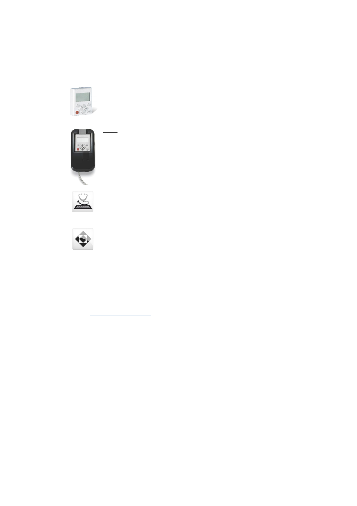
Commissioning via keypad X400 (or diagnosis terminal X400)
The keypad is an alternative to the PC for the local operation, parameterisation, and
diagnostics in a simple manner. The keypad is especially suited for test and
demonstration purposes and for the case that only few parameters have to be
adapted.
Note:
• Use the diagnosis terminal for the 8400 motec inverter. The diagnosis terminal
combines the keypad with a housing and a connecting cable.
• The description how to make the settings with the keypad also applies to the
diagnosis terminal.
Commissioning with PC and »EASY Starter«
The »EASY Starter« is a Lenze tool for easy online diagnostics, parameter setting and
commissioning of the inverter.
Commissioning with PC and »Engineer«
The »Engineer« is a Lenze engineering software for parameter setting across all
devices, configuring and diagnosing individual components (as for instance inverters,
industrial PCs, motors, I/O systems) and machine control systems.
Tip!
The Engineering tools »EASY Starter« and »Engineer StateLevel« are provided free of charge
in the internet:
http://www.Lenze.com
For communication between PC and inverter, the USB diagnostic adapter can be used for
instance (see the following subchapter).
Download Software downloads
22
Lenze · 8400 motec · Reference manual · DMS 10.0 EN · 08/2019 · TD06
Page 23
2 Introduction: Parameterising the inverter
2.2 Selection of the appropriate commissioning tool
_ _ _ _ _ _ _ _ _ _ _ _ _ _ _ _ _ _ _ _ _ _ _ _ _ _ _ _ _ _ _ _ _ _ _ _ _ _ _ _ _ _ _ _ _ _ _ _ _ _ _ _ _ _ _ _ _ _ _ _ _ _ _ _
2.2.1 Overview: Accessories for commissioning
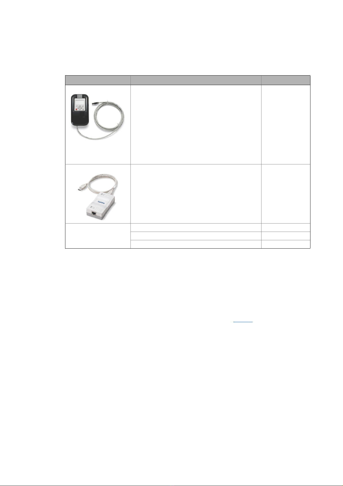
Version Features Product key
Diagnosis terminal X400 Keypad X400 in a robust housing, also suitable for
installation into the control cabinet door.
• Supports hot plugging
• Graphic display with plain texts
• Backlighting
• Easy user guidance
• 4 navigation keys, 2 context-sensitive keys
•Adjustable RUN/STOP function
• Incl. 2.5 m cable
• Enclosure IP20; in case of front installation in control
cabinet IP65
• Can be used for L-force Inverter Drives 8400 and Servo
Drives 9400
USB diagnostic adapter For electrical isolation of your PC and the inverter.
• Supports hot plugging
• Diagnostic LED for data transfer display
• plug and play
• Input-side voltage supply via USB connection from PC
• Output-side voltage supply via the diagnostic interface of
the inverter
• Connecting cables can be selected in various lengths:
EZAEBK2001
E94AZCUS
Connecting cable for
USB diagnostic adapter
2.5 m length EWL0070
5 m length EWL0071
10 m length EWL0072
Fast communication via diagnostic interface
From version 06.01.00, the diagnostic interface also supports the fast communication with
57,600 Baud (instead of 4,800 Baud).
• If no read or write access takes place via the diagnostic interface for 3.5 s, it is changed over to
normal communication again with 4,800 Baud.
• 57,600 Baud are only possible if the 8400 motec comes with the fast diagnostic interface and
an »Engineer« from version 2.19 or a keypad from firmware version 4.2 is connected.
• The current baud rate of the diagnostic interface is displayed in C01905
.
Lenze · 8400 motec · Reference manual · DMS 10.0 EN · 08/2019 · TD06 23
Page 24

2 Introduction: Parameterising the inverter
2.3 General notes on parameters
_ _ _ _ _ _ _ _ _ _ _ _ _ _ _ _ _ _ _ _ _ _ _ _ _ _ _ _ _ _ _ _ _ _ _ _ _ _ _ _ _ _ _ _ _ _ _ _ _ _ _ _ _ _ _ _ _ _ _ _ _ _ _ _
2.3 General notes on parameters
All parameters for inverter parameterising or monitoring are saved as so-called "codes".
• The codes are numbered and indicated by the prefix "C" before the code, e.g. "C00002".
• Moreover, each code has a name and specific attributes, as for example access type (reading,
writing), data type, limit values and default setting ("Lenze setting").
• For the sake of clarity, some codes contain "subcodes" for saving parameters. This Manual uses
a slash "/" as a separator between code and subcode, e.g. C00115/1".
• According to their functionality, the parameters are divided into three groups:
• Setting parameters: For specifying setpoints and for setting device / monitoring functions.
• Configuration parameters: For configuring signal connections and terminal assignments.
• Diagnostic/display parameters: For displaying device-internal process factors, current actual
values and status messages. These are read-only parameters.
24
Lenze · 8400 motec · Reference manual · DMS 10.0 EN · 08/2019 · TD06
Page 25
2 Introduction: Parameterising the inverter
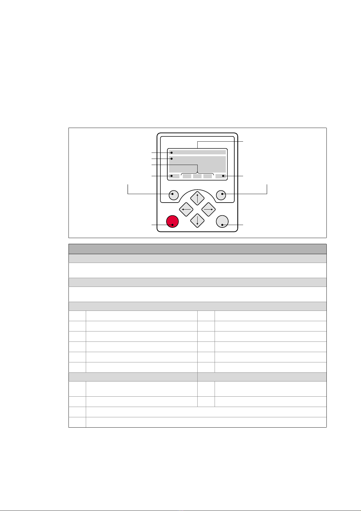
stop run
Headline
Triple-line display
Current function
right function key
Current function
left function key
LCD display
Device state
In manual control mode:
Start motor
In manual control mode:
Stop motor
2.3 General notes on parameters
_ _ _ _ _ _ _ _ _ _ _ _ _ _ _ _ _ _ _ _ _ _ _ _ _ _ _ _ _ _ _ _ _ _ _ _ _ _ _ _ _ _ _ _ _ _ _ _ _ _ _ _ _ _ _ _ _ _ _ _ _ _ _ _
2.3.1 Changing the parameterisation with the keypad
Simply connect the diagnosis terminal to the diagnostic interface being located on the top of the
device.
• The connecting cable can also be connected to the diagnostic interface during operation and
removed again.
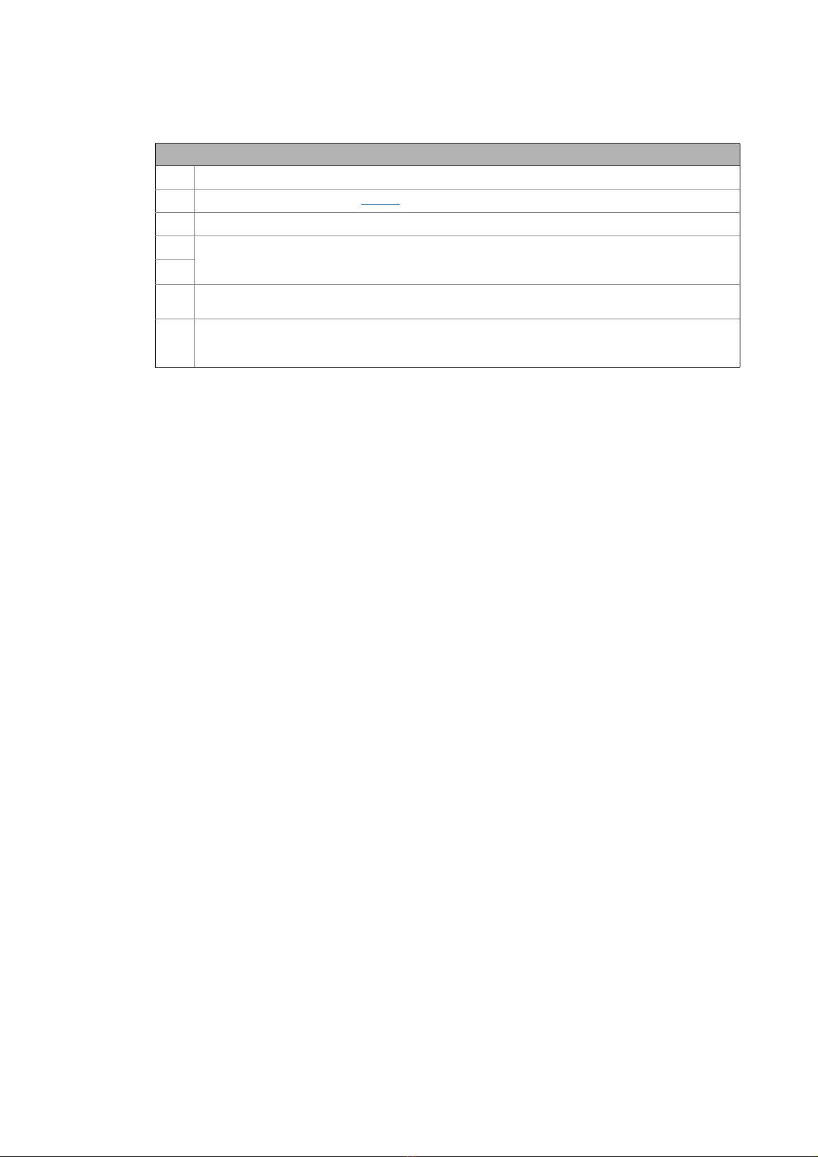
Keypad display and control elements
LCD display
Headline
In the menu level: Menu name
In the parameter level: Parameter name
Three-part display
In the menu level: List of available menus
In the parameter level: Code/subcode and setting or actual value
Device status
Inverter is switched on
Inverter is enabled
Inverter is inhibited
Quick stop active
Current limit exceeded
Speed controller 1 in the limitation
Function - left function key Function - right function key
Change parameter setting
(change to editing mode)
Back to main menu
Parameter can only be changed when the inverter is inhibited
Save all parameter settings in the memory module safe against mains failure
Pulse inhibit active
System fault active
"Fault" device status is active
"Trouble" device status is active
"TroubleQSP" device status is active
A warning is indicated
Accept change in the inverter
(no saving with mains failure protection
Abort (discard change)
)
Lenze · 8400 motec · Reference manual · DMS 10.0 EN · 08/2019 · TD06 25
Page 26
2 Introduction: Parameterising the inverter
2.3 General notes on parameters
_ _ _ _ _ _ _ _ _ _ _ _ _ _ _ _ _ _ _ _ _ _ _ _ _ _ _ _ _ _ _ _ _ _ _ _ _ _ _ _ _ _ _ _ _ _ _ _ _ _ _ _ _ _ _ _ _ _ _ _ _ _ _ _
Control elements
Execute the function assigned to the function key (see LCD display)
Execute the stop function set in C00469 (Lenze setting: Inhibit inverter)
Deactivate stop function again (Lenze setting: Enable inverter again)
In the menu level: Select menu/submenu
In the parameter level: Select parameter
In the editing mode: Change marked digits or select list entry
In the menu level: Select submenu/change to parameter level
In the editing mode: Cursor to the right
In the menu level: One menu level higher (if available)
In the parameter level: Back to the menu level
In the editing mode: Cursor to the left
Menu structure
In the keypad, the parameters are classified into various menus and submenus.
•The USER menu includes a selection of frequently used parameters.
•The Code list contains all parameters.
•The Go to param function enables you to reach the corresponding parameter directly.
•The Logbook logs all errors and their chronological history.
•The Diagnostics menu contains diagnostic/display parameters for displaying device-internal
process factors, current actual values and status messages.
26
Lenze · 8400 motec · Reference manual · DMS 10.0 EN · 08/2019 · TD06
Page 27
2 Introduction: Parameterising the inverter
Load Lenze setting
C00002/001
Off / Finished
EDIT
Par1 8400 protec
SAVE
Code list
Go To Param
USER - Menu
Fixed setpoint 1
C00039/001
40.00 %
EDIT
Fixed setpoint 2
60.00 %
EDIT
C00039/002
Fixed setpoint 2
C00039/002
ESC
60.00 %
OK
1.
2.
3.
5.
4.
6.
2.3 General notes on parameters
_ _ _ _ _ _ _ _ _ _ _ _ _ _ _ _ _ _ _ _ _ _ _ _ _ _ _ _ _ _ _ _ _ _ _ _ _ _ _ _ _ _ _ _ _ _ _ _ _ _ _ _ _ _ _ _ _ _ _ _ _ _ _ _
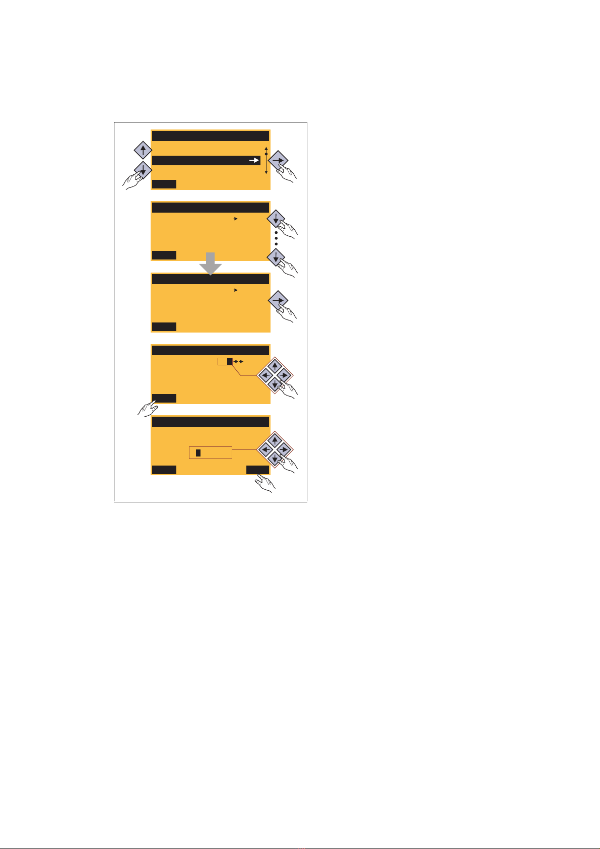
General operation
1. Use the / navigation keys to select the
desired menu.
•Use the / navigation keys to reach a
higher/lower menu level.
•Use the function key to return to the
main menu.
2. Use the / navigation keys to select the
parameter to be set within a submenu.
3. In order to select another subcode in case of a
parameter with subcodes:
• Press the navigation key to change to the
editing mode for the subcode.
• Use the navigation keys to set the desired
subcode.
4. Use the function key to switch over to the
editing mode.
5. Use the navigation keys to set the desired value.
6. Use the function key to accept the change
and to leave the editing mode.
•Use the function key to leave the editing
mode without accepting the change.
[2-2] Example: Changing parameters with the keypad
Lenze · 8400 motec · Reference manual · DMS 10.0 EN · 08/2019 · TD06 27
Page 28
2 Introduction: Parameterising the inverter
2.3 General notes on parameters
_ _ _ _ _ _ _ _ _ _ _ _ _ _ _ _ _ _ _ _ _ _ _ _ _ _ _ _ _ _ _ _ _ _ _ _ _ _ _ _ _ _ _ _ _ _ _ _ _ _ _ _ _ _ _ _ _ _ _ _ _ _ _ _
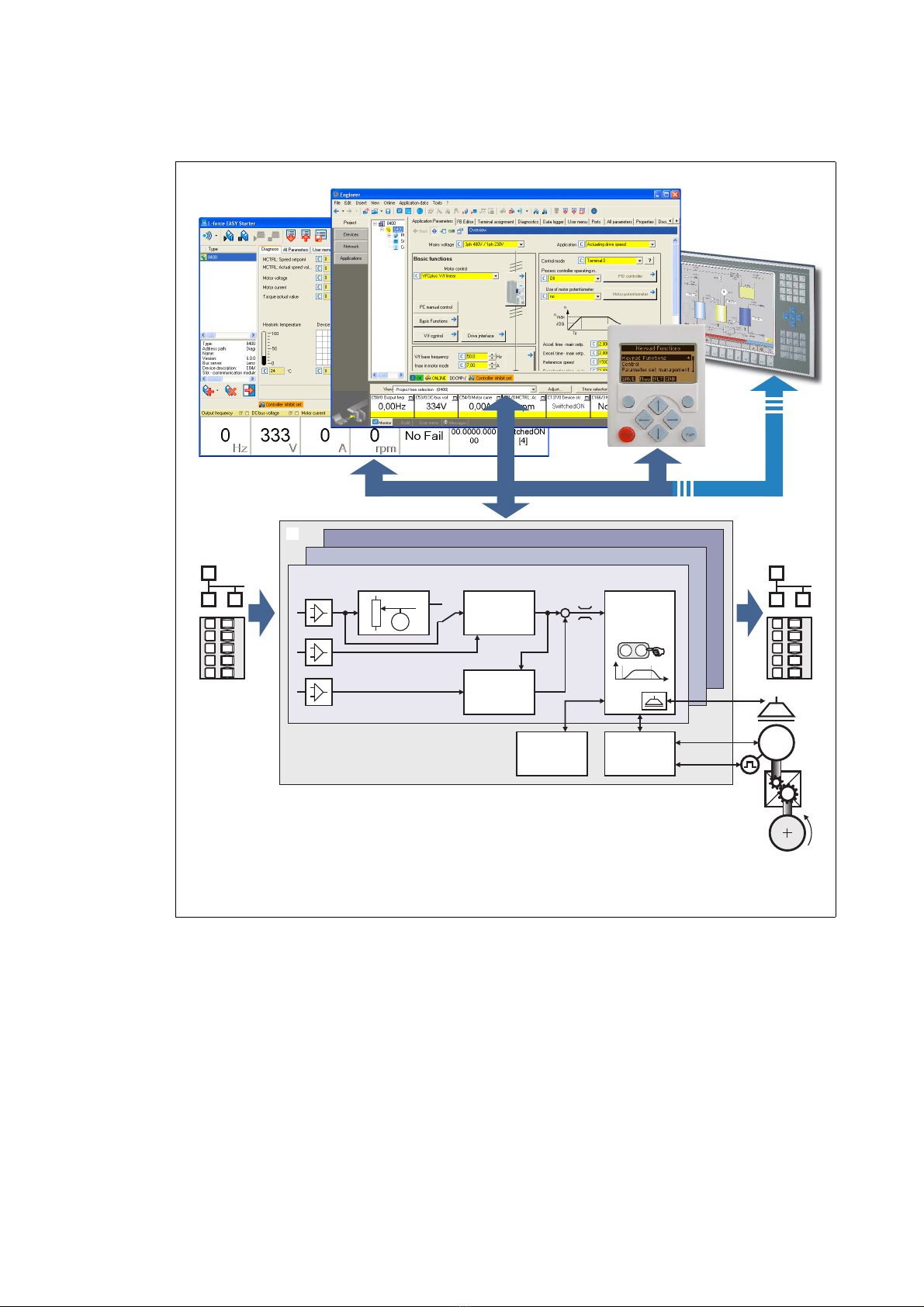
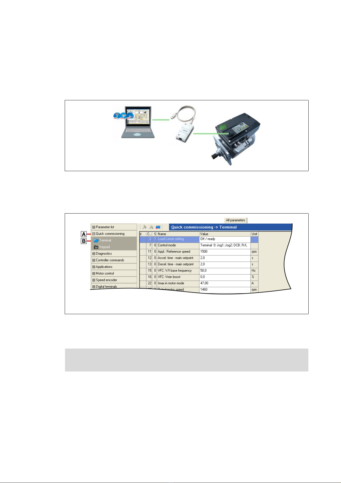
2.3.2 Change parameter settings with PC and Lenze software
For communication between the PC (including the L-force »EASY Starter« or L-force »Engineer«
software) and the inverter, the USB diagnostic adapter can for instance be used, see the following
illustration. The USB diagnostic adapter is the connection between the PC (free USB port) and the
inverter (diagnostic interface).
[2-3] Exemplary constellation for parameterising the inverter
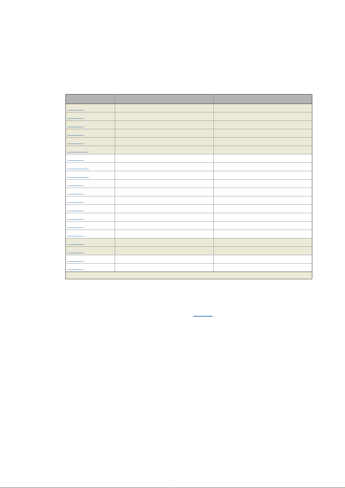
The All parameters tab in the »EASY Starter« and the »Engineer« provides a quick access to all
parameters of the inverter.
The given categories and subcategories correspond 1:1 to the menus and submenus of the keypad:
Category
Subcategories
[2-4] All parameters tab in the »Engineer«
Moreover, the »Engineer« provides a commissioning interface on the Application parameters tab
where you can commission the application in a few steps.
28
Detailed information on how to handle the »Engineer« can be found in the integrated
online help that you can call with the [F1] function key.
Lenze · 8400 motec · Reference manual · DMS 10.0 EN · 08/2019 · TD06
Page 29
2 Introduction: Parameterising the inverter
2.3 General notes on parameters
_ _ _ _ _ _ _ _ _ _ _ _ _ _ _ _ _ _ _ _ _ _ _ _ _ _ _ _ _ _ _ _ _ _ _ _ _ _ _ _ _ _ _ _ _ _ _ _ _ _ _ _ _ _ _ _ _ _ _ _ _ _ _ _
2.3.3 User menu for quick access to frequently used parameters
When a system is installed, parameters must be changed time and again until the system runs
satisfactorily. The user menu of the inverter contains a selection of frequently used parameters to
be able to access and change these parameters quickly:
Parameters Name Lenze setting
C00051 MCTRL: Actual speed value -
C00053 DC-bus voltage -
C00054 Motor current -
C00061 Heatsink temperature -
C00137 Device status -
C00166/3 Mess. - status det. error -
C00011 Appl.: Reference speed 1500 rpm
C00039/1
C00039/2
C00012 Acceleration time - main setpoint 2.0 s
C00013
C00015
C00016
C00022
C00120
C00087
C00099 Firmware version -
C00200 Firmware product type -
C00105
C00173
Greyed out = display parameter
Preset setpoint 1 40.0 %
Preset setpoint 2 60.0 %
Deceleration time - main setpoint 2.0 s
VFC: V/f base frequency 50 Hz
VFC: Vmin boost 0.0 %
Imax in motor mode depending on the device power
Setting of motor overload (I2xt) 100.00 %
Rated motor speed 1460 rpm
Decel. time - quick stop 5.0 s
Mains voltage 0: "3ph 400V"
Tip!
The user menu can be freely configured in C00517
In the »Engineer«, you can configure the user menu comfortably via the User menu tab (see
»Engineer« online help).
Lenze · 8400 motec · Reference manual · DMS 10.0 EN · 08/2019 · TD06 29
.
Page 30

2 Introduction: Parameterising the inverter
2.4 Handling the memory module
_ _ _ _ _ _ _ _ _ _ _ _ _ _ _ _ _ _ _ _ _ _ _ _ _ _ _ _ _ _ _ _ _ _ _ _ _ _ _ _ _ _ _ _ _ _ _ _ _ _ _ _ _ _ _ _ _ _ _ _ _ _ _ _
2.4 Handling the memory module
Danger!
After power-off, wait at least three minutes before working on the inverter. When
removing the memory module, ensure that the inverter is deenergised.
All parameters of the drive system are saved non-volatilely on the memory module. These include
the parameters of the inverter and communication-relevant parameters for the communication
unit used.
The plug-in version is especially suited for
• restoring an application after replacing a device.
• duplicating identical drive tasks within the frequency inverter series8400 motec, e.g. by using
the optionally available EPM Programmer.
Note!
• When the device is switched on, all parameters are automatically loaded from the
memory module to the main memory of the inverter.
• When the DIP1 switch on the S1 DIP switch is in the "ON" position, the inverter
works with the settings made via DIP switches S1 and S2 and displays them in the
corresponding codes.
• The 8400 BaseLine and 8400 motec inverters use the same (grey) memory module.
When handling the memory module, a distinction is drawn between the following scenarios:
Delivery status
• The memory module is plugged into the EPM slot of the drive unit.
• The Lenze setting of the parameters is stored in the memory module.
• The memory module is available as a spare part - without any data.
During operation
• Parameter sets can be saved manually.
• Parameter sets can be loaded manually.
• Parameter changes can be saved automatically.
The memory module can be shifted between these inverters, but the inverter must be
parameterised newly afterwards.
30
Lenze · 8400 motec · Reference manual · DMS 10.0 EN · 08/2019 · TD06
Page 31

2 Introduction: Parameterising the inverter
2.4 Handling the memory module
_ _ _ _ _ _ _ _ _ _ _ _ _ _ _ _ _ _ _ _ _ _ _ _ _ _ _ _ _ _ _ _ _ _ _ _ _ _ _ _ _ _ _ _ _ _ _ _ _ _ _ _ _ _ _ _ _ _ _ _ _ _ _ _
Replacement of the inverter
• In the event of a device replacement, the entire parameter data of an axis can be copied to the
replacement device by "taking along" the memory module, so that additional PC or diagnosis
terminal operations are not required.
• When replacing the inverter, the versions of the old and new device are of importance. Before
data are actually transferred, the versions are checked internally. As a general principle, the
following applies:
• Parameter sets of old devices with V 1.0 can be processed on new devices ≥ V1.0
(downward compatibility).
• Parameters of devices with higher versions are not supported on devices with lower versions.
An error message will be issued if the parameter set versions of the two devices are not
compatible.
Saving the parameters in the memory module safe against mains failure
Inverter parameter changes via the »Engineer«, the diagnosis terminal, or a master control via
fieldbus communication will be lost after mains switching of the inverter unless the settings have
been explicitly saved.
You have several options to avoid data loss by saving the parameter sets in the memory module:
• Automatic saving of parameter changes
• Manual saving of parameter settings
Parameter set transfer using the »Engineer«
When an online connection to the inverter has been established, the following transfer functions
can directly be executed via the Toolbar or the Online menu using the L-force »Engineer«:
Symbol Menu command Shortcut
Download parameter set <F5>
Upload parameter set from device <F7>
Save parameter set
( 67)
( 67)
Tip!
Detailed information on parameter set transfers using the »Engineer« can be found in the
»Engineer« online help.
Lenze · 8400 motec · Reference manual · DMS 10.0 EN · 08/2019 · TD06 31
Page 32

2 Introduction: Parameterising the inverter
2.5 Device identification
_ _ _ _ _ _ _ _ _ _ _ _ _ _ _ _ _ _ _ _ _ _ _ _ _ _ _ _ _ _ _ _ _ _ _ _ _ _ _ _ _ _ _ _ _ _ _ _ _ _ _ _ _ _ _ _ _ _ _ _ _ _ _ _
2.5 Device identification
For device identification, any device name (e.g. wheel drive) with max 32 characters can be set in
C00199/1
2.5.1 Automatic acceptance of the device name in the »Engineer«
If a device name is assigned in C00199/1 and the inverter in the »Engineer« is added to the project
via the Insert Insert device detected online... function, the device name stored in C00199/1
wheel drive) is used as device designation in the Project view instead of the type (8400 motec):
This mechanism also functions in reverse direction:
If you rename the inverter in the project view via <F2>, you will be asked afterwards if you want to
take over the changed name in C00199/1
for the inverter and saved in the memory module with mains failure protection.
(here:
:
32
Lenze · 8400 motec · Reference manual · DMS 10.0 EN · 08/2019 · TD06
Page 33

3 Commissioning
_ _ _ _ _ _ _ _ _ _ _ _ _ _ _ _ _ _ _ _ _ _ _ _ _ _ _ _ _ _ _ _ _ _ _ _ _ _ _ _ _ _ _ _ _ _ _ _ _ _ _ _ _ _ _ _ _ _ _ _ _ _ _ _
3 Commissioning
The 8400 motec inverter is commissioned in one of the following ways:
• Commissioning via PC / »Engineer«
• The »Engineer« provides for convenient access to all parameters of the 8400 motec inverter
and hence offers full flexibility in the commissioning process.
• Commissioning with diagnosis terminal
(If only a few parameters have to be adapted)
With regard to this, please observe the Note
for the SLVC control mode, which is provided from version V09.00.00 onwards.
• Commissioning via the DIP switches/potentiometers at the 8400 motec
(for simple applications)
This chapter provides information on how to commission the 8400 motec using the »Engineer«.
concerning the simplified commissioning process
Information on how to commission the 8400 motec via the DIP switches/
potentiometers can be found in the mounting instructions!
Information on how to commission the 8400 motec using the diagnosis terminal can be
found in the hardware manual!
Lenze · 8400 motec · Reference manual · DMS 10.0 EN · 08/2019 · TD06 33
Page 34

3 Commissioning
3.1 Safety instructions with regard to commissioning
_ _ _ _ _ _ _ _ _ _ _ _ _ _ _ _ _ _ _ _ _ _ _ _ _ _ _ _ _ _ _ _ _ _ _ _ _ _ _ _ _ _ _ _ _ _ _ _ _ _ _ _ _ _ _ _ _ _ _ _ _ _ _ _
3.1 Safety instructions with regard to commissioning
General safety instructions
In order to prevent injury to persons or damage to material assets
• check before connecting the mains voltage
• the wiring for completeness, short circuit, and earth fault
• the "emergency stop" function of the entire system
• that the motor circuit configuration (star/delta) is adapted to the output voltage of the
inverter
• the in-phase connection of the motor
• The direction of rotation or the encoder (if available)
• check the setting of the most important drive parameters before enabling the controller
• the V/f rated frequency must be adapted to the motor circuit configuration!
• the drive parameters relevant for your application must be set correctly!
• the configuration of the I/O terminals must be adapted to the wiring!
• ensure that there are no active speed setpoints before enabling the controller
.
:
Danger!
By default, the RFR control input is connected with a bridge to +24 V, meaning that the
inverter is enabled!
• This input can also be used for switching on/off the drive. For this purpose, the bridge
must be replaced by cabling.
Safety instructions with regard to motor operation
Danger!
• For thermal reasons, continuous operation of self-ventilated motors at a low field
frequency and rated motor current is not permissible!
• In the Lenze setting, the Motor temperature monitoring (PTC)
• In the Lenze setting, the Brake resistor monitoring (I2xt)
the monitoring function causes a switch-off of the braking operation.
• With regard to the setting of the V/f base frequency (C00015
difference to the 8400 StateLine/HighLine/TopLine inverters:
In the case of 8400 motec, the reference voltage for the V/ base frequency is the rated
motor voltage (C00090
voltage).
) according to the motor nameplate (irrespective of the supply
is activated. The activation of
is activated. ( 200)
( 201)
), observe the following
34
Lenze · 8400 motec · Reference manual · DMS 10.0 EN · 08/2019 · TD06
Page 35

3 Commissioning
3.2 Preconditions for commissioning with the »Engineer«
_ _ _ _ _ _ _ _ _ _ _ _ _ _ _ _ _ _ _ _ _ _ _ _ _ _ _ _ _ _ _ _ _ _ _ _ _ _ _ _ _ _ _ _ _ _ _ _ _ _ _ _ _ _ _ _ _ _ _ _ _ _ _ _
3.2 Preconditions for commissioning with the »Engineer«
For commissioning, you need
• a PC that meets the following system requirements:
• a processor with 1.4 GHz or higher
• at least 512 MB RAM and 650 MB free hard disc space
• Microsoft® Windows® 2000 operating system (from service pack 2 onwards) or
Windows® XP
• the Lenze »Engineer« PC software
• a connection to the inverter (via the diagnostic interface or fieldbus)
Tip!
How to obtain/update the »Engineer« software:
• Download from the internet: The full version of the »Engineer StateLevel« is provided
free of charge in the internet:
http://www.Lenze.com
• Requesting the CDYou can also request the »Engineer« separately on CD free of charge
at your Lenze representative. See the "About Lenze" area on our homepage for e.g. the
corresponding German address.
Download Software downloads
3.3 Trouble-shooting during commissioning
When the »Engineer« is used, trouble during commissioning can be detected and eliminated
conveniently. Proceed as follows:
• Check whether error messages appear in the »Engineer«.
•On the Diagnostics tab, relevant actual states of the inverter and pending error messages are
displayed in a well-arranged visualisation.
• Check whether the DIP switches on the Drive Unit are set correctly.
• The »Engineer« serves to display the setting of the DIO switches S1 / S2 and the
potentiometers P1 - P3 on the Diagnostics tab by clicking the DIP switch button.
• Check the input terminals for their corresponding setpoints.
•The Terminal assignment tab displays the current input/output signals.
• Check the signal flow of the application.
• For this purpose, click the Signal flow button on the Application parameter tab. The displayed
signal flow shows active setpoints and their further processing.
Related topics:
Diagnostics & error management
Display of DIP switch positions
LED status display ( 313)
Error messages of the operating system
( 312)
( 317)
( 331)
Lenze · 8400 motec · Reference manual · DMS 10.0 EN · 08/2019 · TD06 35
Page 36

3 Commissioning
3.4 Commissioning wizard 8400
_ _ _ _ _ _ _ _ _ _ _ _ _ _ _ _ _ _ _ _ _ _ _ _ _ _ _ _ _ _ _ _ _ _ _ _ _ _ _ _ _ _ _ _ _ _ _ _ _ _ _ _ _ _ _ _ _ _ _ _ _ _ _ _
3.4 Commissioning wizard 8400
This function extension is supported by the »Engineer« from version 2.15 onwards!
The commissioning wizard 8400 serves to carry out a guided commissioning of the inverter based
on the Lenze setting of the parameters. The set parameters can then be saved in the inverter with
mains failure protection.
Note!
Take all the necessary safety precautions before you carry out the following
commissioning steps and switch the device on!
Safety instructions with regard to commissioning
How to carry out a guided commissioning using the »Engineer«:
1. Go to the Project view and select the 8400 motec inverter.
( 34)
2. Go online.
• After a connection to the inverter has been established, the following status is displayed
in the Status line:
3. Click the icon to open the commissioning wizard 8400 dialog box.
• Now the commissioning wizard guides you step by step through the setting of the
important parameters for a quick commissioning.
•The Next button can only be activated again after all parameter settings in the device
have been reset via the Load Lenze setting button.
36
Lenze · 8400 motec · Reference manual · DMS 10.0 EN · 08/2019 · TD06
Page 37

3 Commissioning
8400 motec
X61
X6
DIAG
U V W DO1 24O GNDNO COM AR AU GND
X3/X4
RFR DI1 DI2 DI3 DI4 DI5 DO1 24O GNDNO COM
M
3~
i
R
1k ... 10kWW
3.5 Commissioning of the "Actuating drive speed" technology application
_ _ _ _ _ _ _ _ _ _ _ _ _ _ _ _ _ _ _ _ _ _ _ _ _ _ _ _ _ _ _ _ _ _ _ _ _ _ _ _ _ _ _ _ _ _ _ _ _ _ _ _ _ _ _ _ _ _ _ _ _ _ _ _
3.5 Commissioning of the "Actuating drive speed" technology application
Note!
Take all the necessary safety precautions before you carry out the following
commissioning steps and switch the device on!
Safety instructions with regard to commissioning
System constellation
AR Reference voltage (10 V) for analog signals
AU Speed setpoint selection (slider of setpoint potentiometer R)
• Scaling: 10 V ≡ 100 % ≡ 1500 rpm
GND Ground potential (GND) for analog signals
RFR Controller enable
DIAG Diagnostic interface for connecting the USB diagnostic adapter
1
(for a 4-pole motor)
( 34)
[3-1] Block diagram for wiring the commissioning example for the "Actuating drive speed" application
Lenze · 8400 motec · Reference manual · DMS 10.0 EN · 08/2019 · TD06 37
Commissioning steps
Find a description of the commissioning steps of the "Actuating drive speed" technology application
below.
Please observe the sequence of the steps in the following chapters and follow them through
carefully. This will help you to commission your inverter quickly and as safely as possible:
( 39)
( 44)
( 44)
Prepare inverter for commissioning
Creating an »Engineer« project & going online
Parameterising the motor control
Parameterise application
( 42)
( 38)
( 40)
Save parameter settings safe against mains failure
Enabling the inverter and selecting the speed
Page 38

3 Commissioning
3.5 Commissioning of the "Actuating drive speed" technology application
_ _ _ _ _ _ _ _ _ _ _ _ _ _ _ _ _ _ _ _ _ _ _ _ _ _ _ _ _ _ _ _ _ _ _ _ _ _ _ _ _ _ _ _ _ _ _ _ _ _ _ _ _ _ _ _ _ _ _ _ _ _ _ _
3.5.1 Prepare inverter for commissioning
1. Wiring the power and control terminals
• Use the mounting instructions supplied with the inverter in order to connect the power and
control terminals correctly.
• Assign the digital inputs so that your application can be displayed by one of the
preconfigured control modes (C00007
Control mode DI1 DI2 DI3 DI4 DI5
Terminals 0 JOG 1/3 JOG 2/3 DCB Cw/Ccw BrkRelease
Terminals 2 JOG 1/3 JOG 2/3 QSP Cw/Ccw BrkRelease
Terminals 11 Cw/Ccw DCB MPotUp MPotDown BrkRelease
Terminal 16 JOG 1/3 JOG 2/3 Cw/QSP Ccw/QSP BrkRelease
Abbreviations used:
JOG Selection of fixed setpoints 1 ... 3 parameterised in C00039/1...3
DCB Manual DC-injection braking
Cw/Ccw CW/CCW rotation
QSP Quick stop
MPotUp Motor potentiometer: Increase speed
MPotDown Motor potentiometer: Reduce speed
Cw/QSP Fail-safe selection of the direction of rotation in connection with quick stop
Ccw/QSP
BrkRelease Release holding brake manually
• In the Lenze setting, the brake control is switched off (not active).
Set operating mode in C02580
) for terminal control:
Assignment of the digital terminals
.
2. Drive Unit: Check DIP switch S1 and DIP switch S2.
• DIP switch S1/DIP1 must be set to "OFF" in order that no parameters of the memory module
are overwritten when the device is started.
•See display parameters C01911
and C01912 for details.
3. Communication Unit CANopen or PROFIBUS: Set DIP switch S3.
• See display parameters C00349 (CANopen) or C13920 (PROFIBUS) for details.
4. Position the drive unit carefully onto the communication unit and fix it using the four screws.
5. Inhibit inverter: Set RFR terminal to LOW level or open the contact.
6. Switch on voltage supply of the inverter.
• Information on some operating states can be quickly obtained via the two-colored LED
display on the top of the device. LED status display
( 313)
7. establish a connection to the inverter, e.g. via a USB diagnostic adapter:
• Remove the cover of the diagnostic interface on the top of the device and connect the USB
diagnostic adapter to the diagnostic interface.
• establish a connection between the USB diagnostic adapter and the PC via a free USB port.
38
Lenze · 8400 motec · Reference manual · DMS 10.0 EN · 08/2019 · TD06
Page 39

3 Commissioning
3.5 Commissioning of the "Actuating drive speed" technology application
_ _ _ _ _ _ _ _ _ _ _ _ _ _ _ _ _ _ _ _ _ _ _ _ _ _ _ _ _ _ _ _ _ _ _ _ _ _ _ _ _ _ _ _ _ _ _ _ _ _ _ _ _ _ _ _ _ _ _ _ _ _ _ _
3.5.2 Creating an »Engineer« project & going online
You can find detailed information on the general use of the »Engineer« in the online help
which you can call with [F1].
• The chapter "Working with projects" describes, among other things, all options of the
Start-up wizard which are available to create a new »Engineer« project.
The following steps serve to describe a general method for creating a project with the Select
component from catalogue option. For this purpose, individual components ( inverter, motor, etc.)
are selected from selection lists.
1. Start »Engineer«.
2. Create a new project with the Start-up wizard and the Select component from catalogue option:
•In the Component step, select the 8400 motec inverter.
• Select the available communication option in the device modules dialog step.
• Select the "actuating drive speed" application in the Application dialog step.
• Select the other components (motor/gearbox) to be added to the project in the Other
components dialog step.
3. Go online.
• After a connection to the inverter has been established, the following status is displayed in
the Status line:
4. Download parameter set.
• This command serves to overwrite the current parameter settings in the inverter by
parameter settings of the »Engineer« project.
Lenze · 8400 motec · Reference manual · DMS 10.0 EN · 08/2019 · TD06 39
Page 40

3 Commissioning
3.5 Commissioning of the "Actuating drive speed" technology application
_ _ _ _ _ _ _ _ _ _ _ _ _ _ _ _ _ _ _ _ _ _ _ _ _ _ _ _ _ _ _ _ _ _ _ _ _ _ _ _ _ _ _ _ _ _ _ _ _ _ _ _ _ _ _ _ _ _ _ _ _ _ _ _
3.5.3 Parameterising the motor control
1. Select the Application parameters tab from the Workspace.
• The motor control parameters, among other things, can be found on the left:
2. In the Motor control list field (C00006
), select the desired motor control.
Note!
In the Lenze setting, the V/f characteristic control (VFCplus) with linear characteristic is
set in C00006
• V/f characteristic control (VFCplus) is a motor control mode for classic frequency
inverter applications on the basis of a simple and robust control procedure for the
operation of machines with a linear or quadratic load torque characteristic (e.g. fans).
• The presettings of the parameters ensure that the inverter is immediately ready for
operation and the motor works adequately without further parameterisation if an
inverter and a 50 Hz asynchronous machine with matching performances are
assigned to each other.
3. Adapt the motor control parameters:
Parameters Lenze setting Information
V/f base frequency
(C00015)
Imax in motor mode
(C00022
Vmin boost
(C00016
)
)
as motor control.
Value Unit
50.0 Hz Adapting the V/f base frequency ( 108)
47.00 A Optimising the Imax controller
0.0 % Adapting the Vmin boost
( 110)
( 109)
40
Lenze · 8400 motec · Reference manual · DMS 10.0 EN · 08/2019 · TD06
Page 41

3 Commissioning
3.5 Commissioning of the "Actuating drive speed" technology application
_ _ _ _ _ _ _ _ _ _ _ _ _ _ _ _ _ _ _ _ _ _ _ _ _ _ _ _ _ _ _ _ _ _ _ _ _ _ _ _ _ _ _ _ _ _ _ _ _ _ _ _ _ _ _ _ _ _ _ _ _ _ _ _
Tip!
Also compare the other information on the nameplate to the motor data set in the inverter.
You can find further information in the chapter entitled "Motor selection/Motor data
( 87)
Recommendations for the following application cases:
• If the inverter and motor show great differences in terms of performance:
set the Imax limit (in motor mode) in C00022
• If a higher starting torque is required:
In idle state of the motor, set the Vmin boost in C00016
motor current flows at a field frequency of f = 3 Hz (display in C00058
• If a high torque must be provided at small speeds without feedback:
Select "Sensorless vector control (SLVC) as motor control mode in C00006
Related topics:
Motor control (MCTRL)
( 85)
to twice the rated motor current.
in such a way that the rated
).
.
".
Selecting the control mode
V/f characteristic control (VFCplus)
Sensorless vector control (SLVC)
( 97)
( 135)
( 103)
Lenze · 8400 motec · Reference manual · DMS 10.0 EN · 08/2019 · TD06 41
Page 42

3 Commissioning
3.5 Commissioning of the "Actuating drive speed" technology application
_ _ _ _ _ _ _ _ _ _ _ _ _ _ _ _ _ _ _ _ _ _ _ _ _ _ _ _ _ _ _ _ _ _ _ _ _ _ _ _ _ _ _ _ _ _ _ _ _ _ _ _ _ _ _ _ _ _ _ _ _ _ _ _
3.5.4 Parameterise application
The application parameters can be found on the right side of the Application parameter tab:
1. Select the required control mode in the Control mode (C00007
• The corresponding wiring diagram is displayed in a pop-up window if you click the button
right to the list field.
• For a detailed description, see the chapter "Terminal assignment of the control modes
( 240)
2. Optional
• For this purpose, select the desired operating mode in the L_PCTRL_1: Operating mode list
• For a detailed description see the L_PCTRL_1
• Go to the parameterisation dialog of the process controller via the Process controller button.
3. Optional
• For this purpose, select "1: On" in the L_MPot_1: Use list field (C00806
• For a detailed description see the L_MPot_1
• Go to the parameterisation dialog of the motor potentiometer via the Motor potentiometer
: Use process controller.
field (C00242
: Use motor potentiometer.
button.
).
function block. ( 499)
function block. ( 488)
) list field.
".
).
42
Lenze · 8400 motec · Reference manual · DMS 10.0 EN · 08/2019 · TD06
Page 43

3 Commissioning
3.5 Commissioning of the "Actuating drive speed" technology application
_ _ _ _ _ _ _ _ _ _ _ _ _ _ _ _ _ _ _ _ _ _ _ _ _ _ _ _ _ _ _ _ _ _ _ _ _ _ _ _ _ _ _ _ _ _ _ _ _ _ _ _ _ _ _ _ _ _ _ _ _ _ _ _
4. Adapt the application parameters:
Parameters Lenze setting Information
Value Unit
Accel. time - main setpoint
(C00012
Decel. time - main setpoint
(C00013
Reference speed
(C00011
Decel. time - quick stop
(C00105
Preset setpoint 1
(C00039/1
Preset setpoint 2
(C00039/2
Preset setpoint 3
(C00039/3
)
)
)
)
)
)
)
2.0 s The setpoint is led via a ramp function generator with
2.0 s
1500 rpm All speed setpoint selections are provided in % and
5.0 s If quick stop is requested, motor control is decoupled
40.0 % A fixed setpoint for the setpoint generator can be
60.0 %
80.0 %
linear characteristic. The ramp function generator
converts setpoint step-changes at the input into a ramp.
L_NSet_1
always refer to the reference speed set in C00011
The motor reference speed is indicated on the motor
nameplate.
from the setpoint selection and, within the deceleration
time parameterised in C00105
a standstill (n
Activate/deactivate quick stop
activated instead of the main setpoint via the selection
inputs bJogSpeed1 and bJogSpeed2.
• Fixed setpoints are selected in [%] based on the
reference speed (C00011
L_NSet_1
( 492)
=0).
act
( 492)
, the motor is brought to
( 68)
).
.
Tip!
•Click the Signal flow button to go down one dialog level to the signal flow of the
application with further possible parameter settings. See chapter "Basic signal flow
( 228)
• The preconfigured I/O connection in the selected control mode can be changed via
configuration parameters. See chapter "User-defined terminal assignment
More detailed informaton on the technology application:
TA "Actuating drive speed"
Interface description
wDriveControl control word
Terminal assignment of the control modes
Setting parameters (short overview)
Pre-assignment of the application
( 227)
( 232)
( 238)
( 240)
( 245)
( 246)
".
". ( 217)
Lenze · 8400 motec · Reference manual · DMS 10.0 EN · 08/2019 · TD06 43
Page 44

3 Commissioning
3.5 Commissioning of the "Actuating drive speed" technology application
_ _ _ _ _ _ _ _ _ _ _ _ _ _ _ _ _ _ _ _ _ _ _ _ _ _ _ _ _ _ _ _ _ _ _ _ _ _ _ _ _ _ _ _ _ _ _ _ _ _ _ _ _ _ _ _ _ _ _ _ _ _ _ _
3.5.5 Save parameter settings safe against mains failure
In order to prevent parameter settings carried out in the device from being lost by mains switching,
you have to explicitly save the parameter set with mains failure protection in the device.
• Saving parameter set
3.5.6 Enabling the inverter and selecting the speed
Stop!
Before stipulating a speed setpoint, check whether the brake in the form of a holding
brake on the motor shaft has been released!
Note!
If the controller is enabled at mains connection and C00142 has activated the "Inhibit at
power-on" auto-start option (Lenze setting), the inverter remains in the
"ReadyToSwitchOn
In order to change to the "SwitchedOn
Set RFR terminal to LOW level.
" state.
" status, controller enable must first be cancelled:
If the inverter is in the "SwitchedOn" state:
1. Enable inverter: Set RFR terminal to HIGH level.
2. Select speed:
• In the "Terminals 0" by selecting a voltage at the analog input or by selecting a fixed setpoint
via the digital inputs DI1/DI2.
DI1 DI2 Speed selection
LOW LOW The main speed setpoint is selected via the analog input 1
•Scaling: 10V ≡ 100 % reference speed (C00011
HIGH LOW The fixed setpoint 1 (C00039/1
• Lenze setting: 40 % of the reference speed (C00011
LOW HIGH The fixed setpoint 2 (C00039/2
• Lenze setting: 60 % of the reference speed (C00011
HIGH HIGH The fixed setpoint 3 (C00039/3
• Lenze setting: 80 % of the reference speed (C00011
) is used as main speed setpoint.
) is used as main speed setpoint.
) is used as main speed setpoint.
)
)
)
)
44
Note!
Observe the actual speed value (display in C00051) and the LED status display on the
inverter.
Lenze · 8400 motec · Reference manual · DMS 10.0 EN · 08/2019 · TD06
Page 45

3 Commissioning
8400 motec
X61
X6
DIAG
U V W DO1 24O GNDNO COM AR AU GND
X3/X4
RFR DI1 DI2 DI3 DI4 DI5 DO1 24O GNDNO COM
t [s]
0
1
QSP
Cw
Ccw
-
DI1
DI2
DI1
DI2
v [m/s]
C00039/3
C00012
C00012
C00013
C00039/3
C00013
Cw
Ccw
Cw
Ccw
M
3~
i
0
1
0
0
1
1
3.6 Commissioning of the "Switch-off positioning" technology application
_ _ _ _ _ _ _ _ _ _ _ _ _ _ _ _ _ _ _ _ _ _ _ _ _ _ _ _ _ _ _ _ _ _ _ _ _ _ _ _ _ _ _ _ _ _ _ _ _ _ _ _ _ _ _ _ _ _ _ _ _ _ _ _
3.6 Commissioning of the "Switch-off positioning" technology application
Note!
Take all the necessary safety precautions before you carry out the following
commissioning steps and switch the device on!
Safety instructions with regard to commissioning
System constellation
( 34)
[3-2] Block diagram for wiring of the commissioning example for the "Switch-off positioning" technology application
RFR Controller enable
DI1 Initiator connection for stop function 1
DI2 Initiator connection for stop function 2
DI3 Quick stop for CW rotation / selection of switch-off position 1
DI4 Quick stop for CCW rotation / selection of switch-off position 2
DIAG Diagnostic interface for connecting the USB diagnostic adapter
Lenze · 8400 motec · Reference manual · DMS 10.0 EN · 08/2019 · TD06 45
Page 46

3 Commissioning
3.6 Commissioning of the "Switch-off positioning" technology application
_ _ _ _ _ _ _ _ _ _ _ _ _ _ _ _ _ _ _ _ _ _ _ _ _ _ _ _ _ _ _ _ _ _ _ _ _ _ _ _ _ _ _ _ _ _ _ _ _ _ _ _ _ _ _ _ _ _ _ _ _ _ _ _
Functional principle of a switch-off positioning without
In case of the switch-off positioning without
"Terminals 2
1. Set DI3 to HIGH level to activate CW rotation.
2. The drive accelerates along the acceleration ramp (C00012
C00039/3
3. After the contact DI1 is reached, the drive is led to the target position along the deceleration
ramp (C00013
4. Reset DI3 to LOW level and set DI4 to HIGH level to activate CCW rotation now.
5. The drive is accelerated along the acceleration ramp (C00012
C00039/3
6. After the contact DI2 is reached, the drive is led to the target position along the deceleration
ramp (C00013
Note: If DI3 and
is led to standstill with quick stop (QSP).
" control mode:
.
) and comes to a standstill there.
.
) and comes to a standstill there.
DI4 are reset to LOW level before the target position has been reached, the drive
pre-switch off shown above, it makes sense to use the
pre-switch off
) up to the traversing speed set in
) up to the traversing speed set in
Tip!
• In order to avoid positioning inaccuracy due to signal propagation delays, the initiators
can be directly evaluated by the inverter. Limit switch evaluation can be configured in
the inverter. In code C00488/x
from level evaluation to edge evaluation.
• In order to prevent unintended movements of the load in the target position, the use of
a holding brake is recommended as an alternative to DC-injection braking (limited
torque).
you can change the method of detecting position signals
Commissioning steps
As shown in illustration [3-2]
off positioning" application without
Please observe the sequence of the steps in the following chapters and follow them through
carefully. This will help you to commission your inverter quickly and as safely as possible:
Prepare inverter for commissioning
Creating an »Engineer« project & going online
Parameterising the motor control
Parameterise application
Save parameter settings safe against mains failure
Enable inverter and test application
, below find a description of the commissioning steps of the "Switch-
pre-switch off.
( 47)
( 48)
( 49)
( 51)
( 53)
( 53)
46
Lenze · 8400 motec · Reference manual · DMS 10.0 EN · 08/2019 · TD06
Page 47

3 Commissioning
NO
COM
AR
AU/AI
GND
RFR
DI1
DI2
DI3
DI4
DI5
DO1
24O
GND
X3/X4
Speed setpoint
Enable controller / reset error message
Stop function 1
Stop function 2
Cw rotat. / QSP/ selection: switch-off pos. 1
Ccw rotat. / QSP/ selection: switch-off pos. 2
Manual release of the holding brake
DriveFail
DriveReady
3.6 Commissioning of the "Switch-off positioning" technology application
_ _ _ _ _ _ _ _ _ _ _ _ _ _ _ _ _ _ _ _ _ _ _ _ _ _ _ _ _ _ _ _ _ _ _ _ _ _ _ _ _ _ _ _ _ _ _ _ _ _ _ _ _ _ _ _ _ _ _ _ _ _ _ _
3.6.1 Prepare inverter for commissioning
1. Wiring the power and control terminals
• Use the mounting instructions supplied with the inverter in order to connect the power and
control terminals correctly.
• In case of the application shown in illustration [3-2]
switch off, wiring according to the "Terminals 2
, switch-off positioning without pre-
" control mode makes sense:
2. Drive Unit: Check DIP switch S1 and DIP switch S2.
• DIP switch S1/DIP1 must be set to "OFF" in order that no parameters of the memory module
are overwritten when the device is started.
•See display parameters C01911
and C01912 for details.
3. Communication Unit CANopen or PROFIBUS: Set DIP switch S3.
• See display parameters C00349 (CANopen) or C13920 (PROFIBUS) for details.
4. Position the drive unit carefully onto the communication unit and fix it using the four screws.
5. Inhibit inverter: Set RFR terminal to LOW level or open the contact.
6. Switch on voltage supply of the inverter.
• Information on some operating states can be quickly obtained via the two-colored LED
display on the top of the device. LED status display
( 313)
7. establish a connection to the inverter, e.g. via a USB diagnostic adapter:
• Remove the cover of the diagnostic interface on the top of the device and connect the USB
diagnostic adapter to the diagnostic interface.
• establish a connection between the USB diagnostic adapter and the PC via a free USB port.
Lenze · 8400 motec · Reference manual · DMS 10.0 EN · 08/2019 · TD06 47
Page 48

3 Commissioning
3.6 Commissioning of the "Switch-off positioning" technology application
_ _ _ _ _ _ _ _ _ _ _ _ _ _ _ _ _ _ _ _ _ _ _ _ _ _ _ _ _ _ _ _ _ _ _ _ _ _ _ _ _ _ _ _ _ _ _ _ _ _ _ _ _ _ _ _ _ _ _ _ _ _ _ _
3.6.2 Creating an »Engineer« project & going online
You can find detailed information on the general use of the »Engineer« in the online help
which you can call with [F1].
• The chapter "Working with projects" describes, among other things, all options of the
Start-up wizard which are available to create a new »Engineer« project.
The following steps serve to describe a general method for creating a project with the Select
component from catalogue option. For this purpose, individual components ( inverter, motor, etc.)
are selected from selection lists.
1. Start »Engineer«.
2. Create a new project with the Start-up wizard and the Select component from catalogue option:
•In the Component step, select the 8400 motec inverter.
• Select the available communication option in the device modules dialog step.
•In the Application step, select the "Switch-off positioning" application. (The application can
also be selected any time afterwards via the Application parameter tab or C00005
• Select the other components (motor/gearbox) to be added to the project in the Other
components dialog step.
.)
3. Go online.
• After a connection to the inverter has been established, the following status is displayed in
the Status line:
4. Transfer parameter set to the device.
• This command serves to overwrite the current parameter settings in the inverter by
parameter settings of the »Engineer« project.
48
Lenze · 8400 motec · Reference manual · DMS 10.0 EN · 08/2019 · TD06
Page 49

3 Commissioning
3.6 Commissioning of the "Switch-off positioning" technology application
_ _ _ _ _ _ _ _ _ _ _ _ _ _ _ _ _ _ _ _ _ _ _ _ _ _ _ _ _ _ _ _ _ _ _ _ _ _ _ _ _ _ _ _ _ _ _ _ _ _ _ _ _ _ _ _ _ _ _ _ _ _ _ _
3.6.3 Parameterising the motor control
1. Select the Application parameters tab from the Workspace.
• The motor control parameters, among other things, can be found on the left:
2. In the Motor control list field (C00006
), select the desired motor control.
Note!
In the Lenze setting, the V/f characteristic control (VFCplus) with linear characteristic is
set in C00006
• V/f characteristic control (VFCplus) is a motor control mode for classic frequency
inverter applications on the basis of a simple and robust control procedure for the
operation of machines with a linear or quadratic load torque characteristic (e.g. fans).
• The presettings of the parameters ensure that the inverter is immediately ready for
operation and the motor works adequately without further parameterisation if an
inverter and a 50 Hz asynchronous machine with matching performances are
assigned to each other.
3. Adapt the motor control parameters:
Parameters Lenze setting Information
V/f base frequency
(C00015)
Imax in motor mode
(C00022
Vmin boost
(C00016
)
)
as motor control.
Value Unit
50.0 Hz Adapting the V/f base frequency ( 108)
47.00 A Optimising the Imax controller
0.0 % Adapting the Vmin boost
( 110)
( 109)
Lenze · 8400 motec · Reference manual · DMS 10.0 EN · 08/2019 · TD06 49
Page 50

3 Commissioning
3.6 Commissioning of the "Switch-off positioning" technology application
_ _ _ _ _ _ _ _ _ _ _ _ _ _ _ _ _ _ _ _ _ _ _ _ _ _ _ _ _ _ _ _ _ _ _ _ _ _ _ _ _ _ _ _ _ _ _ _ _ _ _ _ _ _ _ _ _ _ _ _ _ _ _ _
Tip!
Also compare the other information on the nameplate to the motor data set in the inverter.
You can find further information in the chapter entitled "Motor selection/Motor data
( 87)
Recommendations for the following application cases:
• If the inverter and motor show great differences in terms of performance:
set the Imax limit (in motor mode) in C00022
• If a higher starting torque is required:
In idle state of the motor, set the Vmin boost in C00016
motor current flows at a field frequency of f = 3 Hz (display in C00058
• If a high torque must be provided at small speeds without feedback:
Select "Sensorless vector control (SLVC) as motor control mode in C00006
Related topics:
Motor control (MCTRL)
( 85)
to twice the rated motor current.
in such a way that the rated
).
.
".
Selecting the control mode
V/f characteristic control (VFCplus)
Sensorless vector control (SLVC)
( 97)
( 103)
( 135)
50
Lenze · 8400 motec · Reference manual · DMS 10.0 EN · 08/2019 · TD06
Page 51

3 Commissioning
3.6 Commissioning of the "Switch-off positioning" technology application
_ _ _ _ _ _ _ _ _ _ _ _ _ _ _ _ _ _ _ _ _ _ _ _ _ _ _ _ _ _ _ _ _ _ _ _ _ _ _ _ _ _ _ _ _ _ _ _ _ _ _ _ _ _ _ _ _ _ _ _ _ _ _ _
3.6.4 Parameterise application
The application parameters can be found on the right side of the Application parameter tab:
1. In the Application list field (C00005
• After the "Switch-off positioning" application is selected, the contents of the tab change, e.g.
the Process controller and Motor potentiometer buttons are not shown any more.
2. In the Control mode list field (C00007
off positioning without
• The corresponding wiring diagram is displayed in a pop-up window if you click the button
right to the list field.
• For a detailed description, see the chapter "Terminal assignment of the control modes
( 272)
pre-switch off the "Terminals 2" control mode must be selected.
), select the "switch-off positioning".
) and in case of illustration [3-2], for the shown switch-
".
Lenze · 8400 motec · Reference manual · DMS 10.0 EN · 08/2019 · TD06 51
Page 52

3 Commissioning
3.6 Commissioning of the "Switch-off positioning" technology application
_ _ _ _ _ _ _ _ _ _ _ _ _ _ _ _ _ _ _ _ _ _ _ _ _ _ _ _ _ _ _ _ _ _ _ _ _ _ _ _ _ _ _ _ _ _ _ _ _ _ _ _ _ _ _ _ _ _ _ _ _ _ _ _
3. Adapt the application parameters:
Parameters Lenze setting Information
Value Unit
Accel. time - main setpoint
(C00012
Decel. time - main setpoint
(C00013
Reference speed
(C00011
Decel. time - quick stop
(C00105
Preset setpoint 1
(C00039/1
Preset setpoint 2
(C00039/2
Preset setpoint 3
(C00039/3
)
)
)
)
)
)
)
2.0 s The setpoint is led via a ramp function generator with
2.0 s
1500 rpm All speed setpoint selections are provided in % and
5.0 s If quick stop is requested, motor control is decoupled
40.0 % Fixed setpoints are selected in [%] based on the
60.0 %
80.0 %
linear characteristic. The ramp function generator
converts setpoint step-changes at the input into a ramp.
Note: These settings only apply if no other ramp times
have been selected at the FB L_NSet_1
always refer to the reference speed set in C00011
The motor reference speed is indicated on the motor
nameplate.
from the setpoint selection and, within the deceleration
time parameterised in C00105
a standstill (n
Activate/deactivate quick stop
reference speed (C00011
Fixed setpoint 2 must be smaller than fixed setpoint 3!
Otherwise, the drive will be started with a low speed
and accelerated after the pre-switch off.
act
=0).
).
!
, the motor is brought to
( 68)
.
Tip!
•Click the Signal flow button to go down one dialog level to the signal flow of the
application with further possible parameter settings. See chapter "Basic signal flow
( 268)
• The preconfigured I/O connection in the selected control mode can be changed via
configuration parameters. See chapter "User-defined terminal assignment
". ( 217)
• Low-jerk traversing profiles can be implemented by means of S-shaped ramps.
• In the case of high breakaway torques combined with horizontal motion sequences,
"Sensorless vector control (SLVC)" can be used as motor control (C00006
).
More detailed informaton on the technology application:
TA "Switch-off positioning"
wDriveControl control word
Terminal assignment of the control modes
Setting parameters (short overview)
Pre-assignment of the application
( 264)
( 270)
( 272)
( 279)
( 280)
".
52
Lenze · 8400 motec · Reference manual · DMS 10.0 EN · 08/2019 · TD06
Page 53

3 Commissioning
3.6 Commissioning of the "Switch-off positioning" technology application
_ _ _ _ _ _ _ _ _ _ _ _ _ _ _ _ _ _ _ _ _ _ _ _ _ _ _ _ _ _ _ _ _ _ _ _ _ _ _ _ _ _ _ _ _ _ _ _ _ _ _ _ _ _ _ _ _ _ _ _ _ _ _ _
3.6.5 Save parameter settings safe against mains failure
In order to prevent parameter settings carried out in the device from being lost by mains switching,
you have to explicitly save the parameter set with mains failure protection in the device.
• Save parameter set.
3.6.6 Enable inverter and test application
Stop!
Before stipulating a speed setpoint, check whether the brake in the form of a holding
brake on the motor shaft has been released!
Note!
If the controller is enabled at mains connection and C00142 has activated the "Inhibit at
power-on" auto-start option (Lenze setting), the inverter remains in the
"ReadyToSwitchOn
In order to change to the "SwitchedOn
Set RFR terminal to LOW level.
If the inverter is in the "SwitchedOn" state:
1. Enable inverter: Set RFR terminal to HIGH level.
2. Select the respective control signals via the digital inputs.
" state.
" status, controller enable must first be cancelled:
Note!
Observe the actual speed value (display in C00051) and the LED status display on the
inverter.
Lenze · 8400 motec · Reference manual · DMS 10.0 EN · 08/2019 · TD06 53
Page 54

3 Commissioning
3.7 PC manual control
_ _ _ _ _ _ _ _ _ _ _ _ _ _ _ _ _ _ _ _ _ _ _ _ _ _ _ _ _ _ _ _ _ _ _ _ _ _ _ _ _ _ _ _ _ _ _ _ _ _ _ _ _ _ _ _ _ _ _ _ _ _ _ _
3.7 PC manual control
This function extension is supported by the »Engineer« from version 2.13 onwards!
For the purpose of testing and demonstration and when an online connection has been established,
the PC manual control enables the manual control of various drive functions from the »Engineer«.
Supported drive functions:
• Speed control (follow speed setpoint)
• Activate/deactivate quick stop
More control functions:
• Reset error message
• Set digital/analog outputs (in preparation)
Diagnostic functions:
• Display of the actual speed value and motor current (as time characteristic)
• Display of the current device status
• Display of the status determining error
• Display of the status of the digital/analog inputs (in preparation)
Activate PC manual control
Stop!
PC manual control must be explicitly activated by the user.
If PC manual control is activated, the inverter is inhibited via device command (C00002/
16) first.
Note!
With active PC manual control:
The online connection between PC and controller is monitored by the inverter.
• When the online connection is interrupted for more than 2 s, the "Fault" error
response is triggered, i.e. the motor becomes torqueless and is coasting unless it is
already at a standstill.
PC manual control provides the Motion Control Kernel and the motor interface with all
required control signals and setpoint signals.
• The available application (function block interconnection) is now decoupled from
these interfaces, but is continued to be processed and remains unchanged.
• It does not matter what type of motor control is set in C00006
.
54
Lenze · 8400 motec · Reference manual · DMS 10.0 EN · 08/2019 · TD06
Page 55

3 Commissioning
3.7 PC manual control
_ _ _ _ _ _ _ _ _ _ _ _ _ _ _ _ _ _ _ _ _ _ _ _ _ _ _ _ _ _ _ _ _ _ _ _ _ _ _ _ _ _ _ _ _ _ _ _ _ _ _ _ _ _ _ _ _ _ _ _ _ _ _ _
How to activate the PC manual control:
1. If an online connection to the inverter has not been established yet:
Go online.
2. Select the Application parameters tab from the Workspace.
3. Go to the Overview dialog level and click the "PC manual control" button.
• First, the following safety note is displayed:
•Click the Cancel button to abort the action and close the dialog box.
4. To acknowledge the note and activate PC manual control:
Click the Activate PC manual control button.
• The inverter is inhibited via device command (C00002/16
•The PC manual control operator dialog is displayed.
).
Lenze · 8400 motec · Reference manual · DMS 10.0 EN · 08/2019 · TD06 55
Page 56

3 Commissioning
3.7 PC manual control
_ _ _ _ _ _ _ _ _ _ _ _ _ _ _ _ _ _ _ _ _ _ _ _ _ _ _ _ _ _ _ _ _ _ _ _ _ _ _ _ _ _ _ _ _ _ _ _ _ _ _ _ _ _ _ _ _ _ _ _ _ _ _ _
PC manual control - operator dialog
The PC manual control operator control serves to simply make the drive rotate in the "speed
follower" mode without the need to set control parameters or feedback systems.
Note!
PC manual control can be exited any time by clicking the Close button.
If you exit the PC manual control function, the inverter is inhibited via device command
(C00002/16
standstill yet.
), i.e. the motor goes to a torqueless state and coasts if it is not already at a
56
Lenze · 8400 motec · Reference manual · DMS 10.0 EN · 08/2019 · TD06
Page 57

3 Commissioning
3.7 PC manual control
_ _ _ _ _ _ _ _ _ _ _ _ _ _ _ _ _ _ _ _ _ _ _ _ _ _ _ _ _ _ _ _ _ _ _ _ _ _ _ _ _ _ _ _ _ _ _ _ _ _ _ _ _ _ _ _ _ _ _ _ _ _ _ _
How to easily rotate the motor:
1. Set the desired speed setpoint in [%] based on the reference speed, e.g. directly in the
Setpoint PC input field or via the slider.
•Via the -- / 0 / ++ buttons, the currently set speed setpoint can be reduced/increased in
steps of 10 percent or set to zero.
•Via the Set setpoint A/B buttons, the speed setpoint can be set to a previously set
constant value A/B.
2. To start the speed follower:
Enable the inverter via the Enable controller button.
• Please observe that the inverter will not be enabled if other sources of controller inhibit
(e.g. RFR terminal) are active.
• The enabled drive now follows the defined speed setpoint.
• In order to prevent shocks or overload at higher setpoint changes, the speed setpoint is
lead via a linear ramp generator with adjustable acceleration/deceleration time.
•Via the Inhibit controller button, the inverter can be inhibited again, i.e. the motor
becomes torqueless and is coasting unless it already is at standstill.
Further functions:
•If the Set quick stop (QSP) button is clicked, the motor is braked to a standstill within the
deceleration time parameterised in C00105
•Via the Deactivate quick stop (QSP) button, the quick stop can be deactivated.
•Via the << CCW and CW >> buttons, the direction of rotation can be changed.
.
Lenze · 8400 motec · Reference manual · DMS 10.0 EN · 08/2019 · TD06 57
Page 58

3 Commissioning
Stop
DI3
DI4
DI5
DO1
24O
GND
bRLQCw
bRLQCcw
Enable switchbox
3.8 Control via Field Package ("key-operated switch operation")
_ _ _ _ _ _ _ _ _ _ _ _ _ _ _ _ _ _ _ _ _ _ _ _ _ _ _ _ _ _ _ _ _ _ _ _ _ _ _ _ _ _ _ _ _ _ _ _ _ _ _ _ _ _ _ _ _ _ _ _ _ _ _ _
3.8 Control via Field Package ("key-operated switch operation")
This function extension is only available from version 04.00.00!
Stop!
If manual control is switched off again via key-operated switch, the control of the drive
will be immediately taken over by the terminal or bus control. Available starting
commands are directly accepted unless the controller is inhibited.
In the 8400 motec device version with Field Package, both operator buttons are connected to the
digital inputs DI3, DI4 and DI5 and provide the following function:
Key-operated switch: Activate manual control
Left/right switch: Counter-clockwise rotation (Ccw) - Stop - clockwise rotation (Cw)
[3-3] Field Package functionality
• During operation, the potentiometer P1 serves to adjust the motor speed steplessly within the
range of 0 ... 100 % of the reference speed (C00011
• A different setpoint source can be selected via the configuration parameter C00700/4
• The acceleration/deceleration time can be set in C00461/1
).
.
.
Note!
If the manual control is activated via key-operated switch, the
LA_NCtrl.bRemoteControlActive output signal is set to TRUE.
The key-operated switch operation is activated via C00460
= 1.
58
Lenze · 8400 motec · Reference manual · DMS 10.0 EN · 08/2019 · TD06
Page 59

3 Commissioning
v(t)
t
t
TRUE
FALSE
DI3
LocalSetValue (P1)
LocalSetValue (P1)
0
t
TRUE
FALSE
DI4
t
TRUE
FALSE
DI5
C00461/1
C00461/1
C00461/1
C00461/1
v(t)
t
t
TRUE
FALSE
DI3
LocalSetValue (P1)
0
t
t
TRUE
FALSE
DI5
C00461/1
C00461/1
LED
C00105
01
QSP
QSP
LED
C00105
Firmware-Version < 05.00.00: max. 5 s
3.8 Control via Field Package ("key-operated switch operation")
_ _ _ _ _ _ _ _ _ _ _ _ _ _ _ _ _ _ _ _ _ _ _ _ _ _ _ _ _ _ _ _ _ _ _ _ _ _ _ _ _ _ _ _ _ _ _ _ _ _ _ _ _ _ _ _ _ _ _ _ _ _ _ _
[3-4] Example: Manual control
Special cases
•Special case - direction of rotation is preselected and manual control is switched on via keyoperated switch: The drive is stopped via quick stop. The blue LED status display is blinking to
call the user's attention to the operating error.
• The rotation direction switch has to be first brought into "stop" position before the drive will
be ramped up to setpoint speed.
•Special case - direction of rotation of rotation is preselected and manual control is switched
off via key-operated switch: The drive is stopped via quick stop. The blue LED status display is
blinking during quick stop. When the drive has reached standstill, the quick stop function is
stopped and the drive is again guided to the speed specified by the application.
• Up to and including version 04.xx.xx, the QSP ramp in C00105
After 5 s, the quick stop function is aborted and the drive is again led to the speed specified
by the application.
• From version 05.00.00 onwards, longer QSP ramps are possible.
must be set to maximally 5 s.
Setpoint speed and ramps from the application
[3-5] Example: Special cases regarding manual control
Lenze · 8400 motec · Reference manual · DMS 10.0 EN · 08/2019 · TD06 59
Page 60

3 Commissioning
3.8 Control via Field Package ("key-operated switch operation")
_ _ _ _ _ _ _ _ _ _ _ _ _ _ _ _ _ _ _ _ _ _ _ _ _ _ _ _ _ _ _ _ _ _ _ _ _ _ _ _ _ _ _ _ _ _ _ _ _ _ _ _ _ _ _ _ _ _ _ _ _ _ _ _
Note!
When loading the Lenze setting to the inverter, reset the field package functionality
afterwards using the »Engineer« (see the following instructions).
Starting from version 06.00.00, loading the Lenze setting does not change the C00460
service code anymore.
How to reset the Field Package functionality with the »Engineer«
(e.g. after loading the Lenze setting):
1. Show service codes in the »Engineer«:
• Execute the Extras Options command to open the Options dialog box.
• Go to the Service tab and activate the Show invisible parameters option.
2. Go to the All parameters tab and set the C00460
Package functionality.
The links of the digital inputs DI3, DI4 and DI5 via the configuration parameters C00621
and C00701
sure to not assign more functions to these three digital inputs if the Field Package
functionality is used.
are evaluated independently of the Field Package functionality. Hence, make
service code to "1: On" to activate the Field
60
Lenze · 8400 motec · Reference manual · DMS 10.0 EN · 08/2019 · TD06
Page 61

4 Device control (DCTRL)
_ _ _ _ _ _ _ _ _ _ _ _ _ _ _ _ _ _ _ _ _ _ _ _ _ _ _ _ _ _ _ _ _ _ _ _ _ _ _ _ _ _ _ _ _ _ _ _ _ _ _ _ _ _ _ _ _ _ _ _ _ _ _ _
4 Device control (DCTRL)
This chapter provides information on internal device control as well as the device commands which
can be executed via the subcodes of C00002
• The device control causes the inverter to take defined device statuses.
• The device control provides a multitude of status information in many ways:
• Optically via the LED status display
• As text messages in the Logbook
• As process signals via the outputs of the LS_DriveInterface
• Via diagnostic / display parameters which are included in the »Engineer« parameter list as
well as in the Diagnostics category in the keypad.
.
on the top side of the device. ( 313)
. ( 323)
system block. ( 539)
Note!
The device states of the inverter are based on the operating states of the CiA402
standard. Device state machine and device states
( 72)
Lenze · 8400 motec · Reference manual · DMS 10.0 EN · 08/2019 · TD06 61
Page 62

4 Device control (DCTRL)
_ _ _ _ _ _ _ _ _ _ _ _ _ _ _ _ _ _ _ _ _ _ _ _ _ _ _ _ _ _ _ _ _ _ _ _ _ _ _ _ _ _ _ _ _ _ _ _ _ _ _ _ _ _ _ _ _ _ _ _ _ _ _ _
How to get to the parameterisation dialog of the device control:
1. »Engineer« Go to the Project view and select the 8400 motec inverter.
2. Select the Application parameters tab from the Workspace.
3. Go to the Overview dialog level and click the Drive interface button.
Parameterisation dialog in the »Engineer«
The parameterisation dialog shows the input / output signals and the internal signal flow of the
LS_DriveInterface
system block which displays the device control in the application:
Range / Meaning Display parameter
Display of the internal state machine and the current device status C00137
Display of all active sources of a controller inhibit C00158
Display of all active sources of a quick stop C00159
Display of the status word of the device control C00150
62 Lenze · 8400 motec · Reference manual · DMS 10.0 EN · 08/2019 · TD06
Page 63

4 Device control (DCTRL)
4.1 Device commands (C00002/x)
_ _ _ _ _ _ _ _ _ _ _ _ _ _ _ _ _ _ _ _ _ _ _ _ _ _ _ _ _ _ _ _ _ _ _ _ _ _ _ _ _ _ _ _ _ _ _ _ _ _ _ _ _ _ _ _ _ _ _ _ _ _ _ _
4.1 Device commands (C00002/x)
In the following subchapters, the device commands of the inverter are described, which are
provided in the subcodes of C00002
online connection has been established, or, as an alternative, using the keypad.
The device commands enable direct control of the inverter, the organisation of parameter sets as
well as the call of diagnostic services.
Regarding the execution of the device commands, a distinction is drawn between:
• Device commands which have an immediate effect on control (e.g. "Activate quick stop")
• After being called in C00002/x
("On" or "Off).
• Device commands with longer execution duration (several seconds)
• After being called in C00002/x
"Work in progress".
• The execution of the device command has not finished successfully until the "Off / ready"
status information is provided in C00002/x
• In the event of an error, the "Action cancelled" status information is provided in C00002/x
this case, further details can be obtained from the status of the device command executed
last which is displayed in C00003
and which can be executed from the »Engineer« when an
, these device commands provide static status information
, these device commands provide the status information
.
. In
.
Note!
• Before activating device commands by a master control, wait for the "Ready" signal of
the inverter.
• The device will reject a write process to C00002/x
message.
• C00003
displays the status of the device command that was executed last.
if the value is >1 and issue an error
Detailed information on the various device commands can be found in the following
subchapters.
• Before you follow the instructions provided, ensure that you have selected the
inverter in the Project view.
Lenze · 8400 motec · Reference manual · DMS 10.0 EN · 08/2019 · TD06 63
Page 64

4 Device control (DCTRL)
4.1 Device commands (C00002/x)
_ _ _ _ _ _ _ _ _ _ _ _ _ _ _ _ _ _ _ _ _ _ _ _ _ _ _ _ _ _ _ _ _ _ _ _ _ _ _ _ _ _ _ _ _ _ _ _ _ _ _ _ _ _ _ _ _ _ _ _ _ _ _ _
Short overview of device commands
C00002
Subcode:
* Subcodes which are not listed are reserved for future extensions.
Device command Controller inhibit
required
1 Load Lenze setting
2 Load parameter set 1
7 Save parameter set 1
Save parameter settings
11 Save all parameter sets
Save parameter settings
12 Import EPM data
16 Enable/inhibit inverter
17 Activate/deactivate quick stop
19 Reset error
21 Delete logbook
23 Identify motor parameters
26 CAN reset node
27 Device search function
(from version 04.00.00)
Status information
dynamic
dynamic
dynamic
dynamic
Static
Static
Static
Static
Static
dynamic
Static
Static
Activate device command
When an online connection has been established, simply use the »Engineer« to activate a device
command by selecting the corresponding option from the Parameters tab in C00002/x
"1: On / start").
("0: off" or
• Alternatively, the device command can also be activated via e.g. keypad or through a master
control by writing to C00002/x
.
• Some of the frequently used device commands (such as "Save parameter set") can also be
executed via the Toolbar icons of the »Engineer« when an online connection has been
established:
64
Symbol Function
Enable inverter
Inhibit inverter
Save parameter set (for 8400: Save all parameter sets)
Device search function
(from version 04.00.00)
Note!
Device commands that can be executed via the Toolbar of the »Engineer« always affect
the element currently selected in the Project view including all subelements!
•If no inverter but a system module is selected in the Project view, the corresponding
device command will be activated in all lower-level inverters having an online
connection with the »Engineer«.
Before the desired action is carried out, a confirmation prompt appears first, asking
whether the action is really to be carried out.
Lenze · 8400 motec · Reference manual · DMS 10.0 EN · 08/2019 · TD06
Page 65

4 Device control (DCTRL)
4.1 Device commands (C00002/x)
_ _ _ _ _ _ _ _ _ _ _ _ _ _ _ _ _ _ _ _ _ _ _ _ _ _ _ _ _ _ _ _ _ _ _ _ _ _ _ _ _ _ _ _ _ _ _ _ _ _ _ _ _ _ _ _ _ _ _ _ _ _ _ _
4.1.1 Load Lenze setting
The C00002/1 = "1: On / start" device command resets the parameters to the Lenze setting which
are saved in the inverter firmware.
• Can only be executed if the controller is inhibited; otherwise, the feedback C00002/1
access - controller inhibit" will be returned.
• All parameter changes made since the last saving of the parameter set will get lost!
• This device command has an effect on the settings of the parameters of the operating system,
application and module.
="6: No
Note!
When the Lenze setting C00002/1 is loaded, all communication parameters are reset as
well. After the mains is switched on, the Lenze setting is accepted and the inverter might
not be accessible anymore via the communication module.
From version 10.00.00 onwards, C01004
to prevent all communication parameters from being reset when the Lenze setting
C00002/1
• In order that the communication parameters are not reset while loading the Lenze
setting, you must always set C01004
is loaded.
(Load Lenze setting without C00002/1) serves
:Bit 0 = 1 before mains switching.
How to load the Lenze setting:
1. If the inverter is enabled, it must be inhibited, e.g. by executing the "Enable/Inhibit
inverter" device command "(C00002/16
2. Execute the "Load Lenze setting" device command:
C00002/1
The load process may take a couple of seconds. After the device command has been called
in C00002/1
returned.
="1:On / start"
, a dynamic status information ("Work in progress" "Off / Ready") is
="0:Off/ready").
Lenze · 8400 motec · Reference manual · DMS 10.0 EN · 08/2019 · TD06 65
Page 66

4 Device control (DCTRL)
4.1 Device commands (C00002/x)
_ _ _ _ _ _ _ _ _ _ _ _ _ _ _ _ _ _ _ _ _ _ _ _ _ _ _ _ _ _ _ _ _ _ _ _ _ _ _ _ _ _ _ _ _ _ _ _ _ _ _ _ _ _ _ _ _ _ _ _ _ _ _ _
4.1.2 Load parameter set 1
The C00002/2 = "1: On / start" device command reloads all parameters from the memory module to
the inverter.
• The DIP switches are not used anymore to overwrite data.
• Can only be executed if the controller is inhibited; otherwise, the feedback C00002/2
access - controller inhibit" will be returned.
• All parameter changes made since the last saving of the parameter set will get lost!
• This device command has an effect on the settings of the parameters of the operating system,
application and module.
="6: No
Note!
• When the device is switched on, all parameters are automatically loaded from the
memory module to the main memory of the inverter.
• When the DIP switches are active (DIP switch S1/DIP1 = "ON"), the inverter works
with the settings made via the DIP switches and displays them in the
corresponding codes.
• The inverter has a parameter set.
• Up to 16 freely selectable parameters can be switched over via the basic Parameter
change-over function. ( 290)
How to load the parameter set 1 from the memory module:
1. If the inverter is enabled, it must be inhibited, e.g. by executing the "Enable/Inhibit
inverter" device command "(C00002/16
2. Execute the "Load parameter set 1" device command:
C00002/2
The load process may take a couple of seconds. After the device command has been called
in C00002/2
returned.
="1:On/start"
, a dynamic status information ("Work in progress" "Off / Ready") is
="0:Off/ready").
66
Lenze · 8400 motec · Reference manual · DMS 10.0 EN · 08/2019 · TD06
Page 67

4 Device control (DCTRL)
4.1 Device commands (C00002/x)
_ _ _ _ _ _ _ _ _ _ _ _ _ _ _ _ _ _ _ _ _ _ _ _ _ _ _ _ _ _ _ _ _ _ _ _ _ _ _ _ _ _ _ _ _ _ _ _ _ _ _ _ _ _ _ _ _ _ _ _ _ _ _ _
4.1.3 Save parameter settings
If parameter settings are changed in the inverter, those changes will be lost after mains switching
of the inverter unless the settings have been saved explicitly.
Note!
How to prevent a data loss:
• Do not switch off the supply voltage during the saving process.
• Only unplug the memory module if the device is switched off.
Manual saving of parameter settings
The C00002/7
mains failure to the memory module of the inverter.
Automatic saving of parameter changes
= "1: On / start" device command saves the current parameter settings safe against
Stop!
Activating this function is not permissible if parameters are changed very frequently
(e.g. in case of cyclic writing of parameters via a bus system).
The maximum service life of the memory module amounts to one million writing cycles.
Make sure that this value will not be reached.
When you select "1: active" in C00141/1
is saved automatically in the memory module. Thus, manual saving of parameter sets is not
required anymore.
4.1.4 Import EPM data
The C00002/12 = "1: On / start" device command activates the automatic import of parameters
from the memory module after the error message "PS04: Par.set incompatible".
•The C00002/12
, automatic saving is activated and every parameter change
= "0: Off / ready" device command deactivates this function again.
Lenze · 8400 motec · Reference manual · DMS 10.0 EN · 08/2019 · TD06 67
Page 68

4 Device control (DCTRL)
4.1 Device commands (C00002/x)
_ _ _ _ _ _ _ _ _ _ _ _ _ _ _ _ _ _ _ _ _ _ _ _ _ _ _ _ _ _ _ _ _ _ _ _ _ _ _ _ _ _ _ _ _ _ _ _ _ _ _ _ _ _ _ _ _ _ _ _ _ _ _ _
4.1.5 Enable/inhibit inverter
The C00002/16 = "1: On / start" device command enables the inverter, provided that no other
source of an inverter inhibit is active.
The C00002/16
stages in the inverter are inhibited and the speed/current controllers of the motor control are reset.
• The motor becomes torqueless and coasts down.
• When the controller is inhibited, the status output bCInhActive of the LS_DriveInterface
block is set to TRUE.
• When the controller inhibit request is reset, the drive synchronises to the actual speed. For this
purpose,
• If the flying restart circuit is activated in C00990
C00991
function ( 171)
• In the case of an operation with feedback, the actual speed is read out by the encoder system.
= "0: Off / ready" device command inhibits the inverter again, i.e. the power output
is used for the synchronisation to the rotary or standing drive. Flying restart
Tip!
• The inverter can also be enabled or inhibited via the and toolbar icons.
• C00158
inhibit.
4.1.6 Activate/deactivate quick stop
The C00002/17 = "1: On / start" device command activates the quick stop function, i.e. the motor
control is separated from the setpoint selection, and within the deceleration time parameterised
inC00105
the motor is brought to a standstill (n
provides a bit coded representation of all active sources/triggers of a controller
, the flying restart function parameterised in
=0).
act
system
Parameters Information Lenze setting
Value Unit
C00105 Decel. time - quick stop 2.000 s
• The motor is kept at a standstill during closed-loop operation.
• A pulse inhibit (CINH) is set if the auto-DCB function has been activated via C00019
The C00002/17
no other source of a quick stop is active.
= "0: Off / ready" device command deactivates the quick stop again, provided that
Tip!
C00159
displays a bit code of active sources/causes for the quick stop.
.
68
Lenze · 8400 motec · Reference manual · DMS 10.0 EN · 08/2019 · TD06
Page 69

4 Device control (DCTRL)
4.1 Device commands (C00002/x)
_ _ _ _ _ _ _ _ _ _ _ _ _ _ _ _ _ _ _ _ _ _ _ _ _ _ _ _ _ _ _ _ _ _ _ _ _ _ _ _ _ _ _ _ _ _ _ _ _ _ _ _ _ _ _ _ _ _ _ _ _ _ _ _
4.1.7 Reset error
The C00002/19 = "1: On / start" device command acknowledges an existing error message if the
error cause has been eliminated and thus the error is no longer pending.
• After the reset (acknowledgement) of the current error, further errors may be pending which
must also be reset.
• The status determining error is displayed in C00168
.
Tip!
An error message can also be acknowledged by activating the Reset error button in the
Diagnostics tab.
In the Lenze setting, switching RFR causes also causes an error acknowledgement (see
configuration parameter C00701/2
Detailed information on error messages can be found in the "Diagnostics & error
management" chapter. ( 312)
).
4.1.8 Delete logbook
The C00002/21 = "1: On / start" device command deletes all logbook entries.
Tip!
To display the logbook in the »Engineer«, click the Logbook button on the Diagnostics tab.
In the Logbook dialog box, it is also possible to delete all logbook entries by clicking the
Delete button.
Detailed information on the logbook can be found in the "Diagnostics & error
management" chapter. ( 312)
Lenze · 8400 motec · Reference manual · DMS 10.0 EN · 08/2019 · TD06 69
Page 70

4 Device control (DCTRL)
4.1 Device commands (C00002/x)
_ _ _ _ _ _ _ _ _ _ _ _ _ _ _ _ _ _ _ _ _ _ _ _ _ _ _ _ _ _ _ _ _ _ _ _ _ _ _ _ _ _ _ _ _ _ _ _ _ _ _ _ _ _ _ _ _ _ _ _ _ _ _ _
4.1.9 Identify motor parameters
The C00002/23 = "1: On / start" device command performs automatic identification of the motor
parameters.
• The device command is only executed if the inverter is in the "SwitchedOn
• In order to identify the motor parameters, the inverter must be enabled after this device
command.
• After that it changes to the "MotorIdent
• After successful identification, it changes back to the "SwitchedOn
• The motor model implemented in the 8400 motec cannot be used to identify a synchronous
motor.
•If the "SLPSM: Sensorless PSM" motor control has been selected in C00006
automatically shown in C00002/23
Tip!
For identifying a synchronous motor, you can use e.g. an 8400 HighLine. Afterwards, the
detected data has to be transferred manually to the 8400 motec. Please contact your Lenze
service partner if you need support in this matter.
Detailed information on automatic identification of motor parameters can be found in the
"Automatic motor data identification
4.1.10 CAN reset node
The C00002/26 = "1: On / start" device command reinitialises the CAN interface of the "CAN"
communication unit, which is required after e.g. changing the data transfer rate, the node address,
or identifiers.
" state.
" device state.
" device status.
, "5: No access" is
.
" subchapter on motor control (MCTRL). ( 95)
Detailed information on the "CAN" communication unit can be found in the
corresponding online help and in the communication manual (KHB).
70
Lenze · 8400 motec · Reference manual · DMS 10.0 EN · 08/2019 · TD06
Page 71

4 Device control (DCTRL)
4.1 Device commands (C00002/x)
_ _ _ _ _ _ _ _ _ _ _ _ _ _ _ _ _ _ _ _ _ _ _ _ _ _ _ _ _ _ _ _ _ _ _ _ _ _ _ _ _ _ _ _ _ _ _ _ _ _ _ _ _ _ _ _ _ _ _ _ _ _ _ _
4.1.11 Device search function
This function extension is only available from version 04.00.00!
In some applications where inverters are housed in a spacious plant, it is often difficult to locate a
device connected online, for instance to carry out maintenance work on this device. There is an
established online connection with the inverter, but you do not know where the inverter is located
physically.
The C00002/27
• The LED status display at the front of the device flashes blue for the time set in C00181/1
function then switches off automatically.
• If the device command is executed again within the set time period, the duration is extended
accordingly.
• The setting C00002/27
• Adjustable time period: 0 ... 6000 s (Lenze setting: 5 s)
= "1: On / start" device command serves to carry out an "optical location":
. The
= "0: Off / ready" serves to abort or switch off the function.
Tip!
The device search function can also be activated via the toolbar icon.
Lenze · 8400 motec · Reference manual · DMS 10.0 EN · 08/2019 · TD06 71
Page 72

4 Device control (DCTRL)
ReadyTo
SwitchOn
3
SwitchedOn
4
Operation
Enabled
5
Trouble
7
0
SafeTorqueOff
10
0
MotorIdent
2
1
Warning
Fault
8
Init
1
Power on
4.2 Device state machine and device states
_ _ _ _ _ _ _ _ _ _ _ _ _ _ _ _ _ _ _ _ _ _ _ _ _ _ _ _ _ _ _ _ _ _ _ _ _ _ _ _ _ _ _ _ _ _ _ _ _ _ _ _ _ _ _ _ _ _ _ _ _ _ _ _
4.2 Device state machine and device states
The behaviour of the inverter is mainly determined by the current device status within the device
state machine. Which device status is active and which device status is next depends on certain
control signals (e.g. for controller inhibit and quick stop) and status parameters.
Device state machine
Grey field: Pulse inhibit
Can be reached from all statuses.
"Warning" contradicts the definition of a device status. In fact, it is a message which is to call attention to
the device status the warning exists for.
"Warning" can occur in parallel to other device states.
• The arrows between the device states mark possible state changes.
• The digits stand for the status ID (see table below).
72
Lenze · 8400 motec · Reference manual · DMS 10.0 EN · 08/2019 · TD06
Page 73

4 Device control (DCTRL)
4.2 Device state machine and device states
_ _ _ _ _ _ _ _ _ _ _ _ _ _ _ _ _ _ _ _ _ _ _ _ _ _ _ _ _ _ _ _ _ _ _ _ _ _ _ _ _ _ _ _ _ _ _ _ _ _ _ _ _ _ _ _ _ _ _ _ _ _ _ _
• The change from one state to another is done in a 1 ms cycle. If, at the same time, several state
change requests exist, the state with the higher priority is processed first (see the following
table).
•The C00137
• C00150
displays the current device status.
(status word) provides a bit coded representation of the current device status via bits
8 ... 11 (see table below).
ID Device status
(Display in C00137
0 - (Reserved) - 0 0 0 0 -
1 Init
2 MotorIdent
3 ReadyToSwitchOn
4 SwitchedOn
5 OperationEnabled
6 - (Reserved) - 0 1 1 0 -
7 Trouble
8 Fault
9 - (Reserved) - 1 0 0 1 -
10 SafeTorqueOff
11 - (Reserved) - 1 0 1 1 -
... ... ... ... ...
15 - (Reserved) - 1 1 1 1 -
)
Priority
1=lowest
6=highest
- 0 0 0 1 Initialisation active
- 0 0 1 0 Motor parameter identification is
4 0011Device is ready to start
3 0 1 0 0 Device is switched on
1 0101Operation
2 0111Trouble active
6 1000Error active
5 1 0 1 0 Safe torque off is active
Bit 11 Bit 10 Bit 9 Bit 8
Status bits
(Display in C00150
)
Meaning
active
[4-1] Device statuses, priorities, and meaning of the status bits in the status word
Lenze · 8400 motec · Reference manual · DMS 10.0 EN · 08/2019 · TD06 73
Page 74

4 Device control (DCTRL)
4.2 Device state machine and device states
_ _ _ _ _ _ _ _ _ _ _ _ _ _ _ _ _ _ _ _ _ _ _ _ _ _ _ _ _ _ _ _ _ _ _ _ _ _ _ _ _ _ _ _ _ _ _ _ _ _ _ _ _ _ _ _ _ _ _ _ _ _ _ _
4.2.1 Init
LED status display Display in C00137 Display in status word 1 (C00150)
Bit 11 Bit 10 Bit 9 Bit 8
Init 0001
The "Init" device status
• is the inverter's status directly after the supply voltage has been switched on.
• is the state in which the operating system is initialised.
• is the state in which all device components (power section, communication unit, etc) are
identified.
• is the state in which the parameters are imported from the memory module.
• is the state in which the settings of the DIP switches are read in and parameters are overwritten.
• is the state in which it is checked whether the DC-bus voltage is within the tolerance zone and
the precharge relay is closed.
• is the state in which the inverter is inhibited, i.e. there is no voltage output at the motor
terminals.
• is the state in which communication via fieldbus or diagnostic interface is not working yet.
• is the state in which the application is not processed yet.
• is the state in which the monitoring mode is not active yet.
• is the state in which the inverter cannot be parameterised yet and no device commands can be
carried out yet.
Note!
If the initialisation is completed, it changes automatically to the "ReadyToSwitchOn"
device state.
74
Lenze · 8400 motec · Reference manual · DMS 10.0 EN · 08/2019 · TD06
Page 75

4 Device control (DCTRL)
4.2 Device state machine and device states
_ _ _ _ _ _ _ _ _ _ _ _ _ _ _ _ _ _ _ _ _ _ _ _ _ _ _ _ _ _ _ _ _ _ _ _ _ _ _ _ _ _ _ _ _ _ _ _ _ _ _ _ _ _ _ _ _ _ _ _ _ _ _ _
4.2.2 MotorIdent
LED status display Display in C00137 Display in status word 1 (C00150)
Bit 11 Bit 10 Bit 9 Bit 8
MotorIdent 0010
The "MotorIdent" device state
• is the state which the inverter is in if, in the "SwitchedOn
parameters" device command is activated and the inverter is enabled.
• the application remains active.
• all system interfaces (IO, bus systems, etc.) remain active.
• error monitoring remains active
• the inverter is controlled independently of the setpoint sources.
" status, the "Identify motor
Stop!
During the motor parameter identification process, the inverter does not respond to
setpoint changes or control processes, (e.g. speed setpoints, quick stop, torque
limitations).
After the motor parameter identification is completed, the status changes back to "SwitchedOn
Tip!
Detailed information on motor parameter identification can be found in the "Automatic
motor data identification" subchapter on motor control. ( 95)
4.2.3 SafeTorqueOff
LED status display Display in C00137 Display in status word 1 (C00150)
In the "SafeTorqueOff" device state
• the controller can only be if the used communication unit has the safety option and
of the two channels SIA/SIB of the safe input is set to LOW level.
• the next transaction to the "ReadyToSwitchOn
".
Bit 11 Bit 10 Bit 9 Bit 8
SafeTorqueOff 1010
at least one
" state takes place.
Detailed and important information on the integrated safety system can be found in the
hardware manual!
Lenze · 8400 motec · Reference manual · DMS 10.0 EN · 08/2019 · TD06 75
Page 76

4 Device control (DCTRL)
4.2 Device state machine and device states
_ _ _ _ _ _ _ _ _ _ _ _ _ _ _ _ _ _ _ _ _ _ _ _ _ _ _ _ _ _ _ _ _ _ _ _ _ _ _ _ _ _ _ _ _ _ _ _ _ _ _ _ _ _ _ _ _ _ _ _ _ _ _ _
4.2.4 ReadyToSwitchOn
LED status display Display in C00137 Display in status word 1 (C00150)
Bit 11 Bit 10 Bit 9 Bit 8
ReadyToSwitchOn 0011
The "ReadyToSwitchOn" device state
• is the state which the inverter is in after the initialisation process has been completed
successfully.
• is the state which the inverter is also in after "Trouble
reset.
• is the state which the inverter is also in if bit 0 ("SwitchOn") in the MCI/CAN control word is not
set.
• Display parameter for MCI/CAN control word: C00136/1
• Configuration parameter for MCI/CAN control word: C00700/5
• is the state in which I/O signals are evaluated.
• is the state in which the monitoring modes are active.
• is the state in which the inverter can be parameterised.
• the application is basically executable.
• prevents in the Lenze setting the auto-start option " Inhibit at power-on" activated in C00142
from changing to the "SwitchedOn
Danger!
If the "Inhibit at power-on" auto-start option has been deactivated in C00142, the
"ReadyToSwitchOn status switches directly to the "SwitchedOn
connection.
Auto-start option "Inhibit at power-on"
" state.
( 81)
" "Fault", or "SafeTorqueOff" has been
"
" status after mains
76
Lenze · 8400 motec · Reference manual · DMS 10.0 EN · 08/2019 · TD06
Page 77

4 Device control (DCTRL)
4.2 Device state machine and device states
_ _ _ _ _ _ _ _ _ _ _ _ _ _ _ _ _ _ _ _ _ _ _ _ _ _ _ _ _ _ _ _ _ _ _ _ _ _ _ _ _ _ _ _ _ _ _ _ _ _ _ _ _ _ _ _ _ _ _ _ _ _ _ _
4.2.5 SwitchedOn
LED status display Display in C00137 Display in status word 1 (C00150)
Bit 11 Bit 10 Bit 9 Bit 8
SwitchedON 0100
The "SwitchedOn" device state
• is the state which the inverter is in if the user has inhibited the inverter (and no error is pending).
• is the state in which I/O signals are evaluated.
• is the state in which the monitoring modes are active.
• is the state in which the inverter can be parameterised.
• the application is basically executable.
• it can be changed to the "OperationEnabled
" state by deactivating the controller inhibit.
Tip!
C00158
inhibit.
provides a bit coded representation of all active sources/triggers of a controller
Depending on certain conditions, a status change takes place based on the "SwitchedOn" device
status:
Change condition Changeover to the device status
Control bit "EnableOperation" in control word wDriveControl = "1"
AND terminal RFR = HIGH level (controller enable)
Control bit "SwitchOn" = "0". ReadyToSwitchOn
Motor parameter identification requested. MotorIdent
Undervoltage in the DC bus. Trouble/Fault (depending on C00600/1)
Error with error response "Trouble" occurs. Trouble
Related topics:
wDriveControl control word
( 238)
OperationEnabled
Lenze · 8400 motec · Reference manual · DMS 10.0 EN · 08/2019 · TD06 77
Page 78

4 Device control (DCTRL)
4.2 Device state machine and device states
_ _ _ _ _ _ _ _ _ _ _ _ _ _ _ _ _ _ _ _ _ _ _ _ _ _ _ _ _ _ _ _ _ _ _ _ _ _ _ _ _ _ _ _ _ _ _ _ _ _ _ _ _ _ _ _ _ _ _ _ _ _ _ _
4.2.6 OperationEnabled
LED status display Display in C00137 Display in status word 1 (C00150)
Bit 11 Bit 10 Bit 9 Bit 8
OperationEnabled 0 1 0 1
The "OperationEnabled" state
• is the state which the inverter is in if controller inhibit is deactivated and no trouble ("Trouble")
or fault ("Fault") is pending.
• the operation is enabled and the motor follows the setpoint defined by the active application
(with sensorless vector control only after magnetisation has been completed).
Depending on certain conditions, a status change takes place based on the "OperationEnabled"
device status.
Change condition Changeover to the device status
Control bit "EnableOperation" in control word wDriveControl = "0"
OR terminal RFR = LOW level (controller inhibit).
Control bit "SwitchOn" = "0". ReadyToSwitchOn
Undervoltage in the DC bus. Trouble/Fault (depending on C00600/1)
Error with error response "Trouble" occurs. Trouble
SwitchedOn
Related topics:
wDriveControl control word
( 238)
78
Lenze · 8400 motec · Reference manual · DMS 10.0 EN · 08/2019 · TD06
Page 79

4 Device control (DCTRL)
4.2 Device state machine and device states
_ _ _ _ _ _ _ _ _ _ _ _ _ _ _ _ _ _ _ _ _ _ _ _ _ _ _ _ _ _ _ _ _ _ _ _ _ _ _ _ _ _ _ _ _ _ _ _ _ _ _ _ _ _ _ _ _ _ _ _ _ _ _ _
4.2.7 Trouble
LED status display Display in C00137 Display in status word 1 (C00150)
Bit 11 Bit 10 Bit 9 Bit 8
Trouble 0111
The "Trouble" device state
• is the state which the inverter is in if a monitoring function has caused a "Trouble" error
response.
• the motor has no torque (is coasting) due to the inhibit of the inverter.
Note!
The "Trouble" device status is automatically exited if the error cause has been removed.
If in C00142
inhibit is required before this status can be abandoned.
the "Inhibit at trouble" is activated, explicit deactivation of the controller
Depending on certain conditions a status change takes place based on the "Trouble" device status.
Change condition Changeover to the device status
The error cause is no longer active. ReadyToSwitchOn
Control bit "EnableOperation" in control word wDriveControl = "1"
AND terminal RFR = HIGH level (controller enable)
AND the message has been cancelled.
Control bit "EnableOperation" in control word wDriveControl = "0"
OR terminal RFR = LOW level (controller inhibit)
AND the message has been cancelled.
Related topics:
wDriveControl control word
Basics on error handling in the inverter
Error messages of the operating system
( 238)
( 312)
( 331)
OperationEnabled
SwitchedOn
Lenze · 8400 motec · Reference manual · DMS 10.0 EN · 08/2019 · TD06 79
Page 80

4 Device control (DCTRL)
4.2 Device state machine and device states
_ _ _ _ _ _ _ _ _ _ _ _ _ _ _ _ _ _ _ _ _ _ _ _ _ _ _ _ _ _ _ _ _ _ _ _ _ _ _ _ _ _ _ _ _ _ _ _ _ _ _ _ _ _ _ _ _ _ _ _ _ _ _ _
4.2.8 Fault
LED status display Display in C00137 Display in status word 1 (C00150)
Bit 11 Bit 10 Bit 9 Bit 8
Fault 1000
The "Fault" device state
• is the state which the inverter is in if a monitoring function has caused a "Fault" error response.
• the motor has no torque (is coasting) due to the inhibit of the inverter.
The error must explicitly be reset ("acknowledged") in order to exit the device state, e.g. by the
device command "Reset error
" or via the control bit "ResetFault" in the control word wDriveControl.
Note!
If an undervoltage in the DC bus of the inverter occurs (error message "LU"), the device
changes to the "Trouble
" status.
An additional error of higher priority leads the device into the "Fault
According to the Device state machine
status after acknowledging the error although the undervoltage is still available!
If the "Inhibit at fault" auto-start option has been activated in C00142
deactivation of the controller inhibit is required before the status can be abandoned.
Related topics:
wDriveControl control word
Basics on error handling in the inverter
Error messages of the operating system
( 238)
, the device changes to the "ReadyToSwitchOn"
( 312)
( 331)
" status.
, explicit
80
Lenze · 8400 motec · Reference manual · DMS 10.0 EN · 08/2019 · TD06
Page 81

4 Device control (DCTRL)
4.3 Auto-start option "Inhibit at power-on"
_ _ _ _ _ _ _ _ _ _ _ _ _ _ _ _ _ _ _ _ _ _ _ _ _ _ _ _ _ _ _ _ _ _ _ _ _ _ _ _ _ _ _ _ _ _ _ _ _ _ _ _ _ _ _ _ _ _ _ _ _ _ _ _
4.3 Auto-start option "Inhibit at power-on"
prevents in the Lenze setting the auto-start option "Inhibit at power-on" activated in C00142 " from
changing to the "SwitchedOn
" state.
Danger!
When the auto-start option "Inhibit at power-on" is deactivated, the motor can directly
start after power-on if the controller is enabled!
The following three cases describe the behaviour of the inverter after mains connection depending
on whether the controller is enabled and the set auto-start option. Here, it is assumed that after
mains connection, no errors and trouble occur in the inverter and the "EnableOperation" control bit
in the wDriveControl is set to "1".
Lenze · 8400 motec · Reference manual · DMS 10.0 EN · 08/2019 · TD06 81
Page 82

4 Device control (DCTRL)
1: Init
3: ReadyToSwitchOn
4: SwitchedOn
5: OperationEnabled
C00137
t
t
0
1
RFR
t
0
1
t
Trouble
7:Trouble
1: Init
3: ReadyToSwitchOn
4: SwitchedOn
5: OperationEnabled
C00137
t
t
0
1
RFR
t
0
1
t
Fault
8:Fault
1: Init
3: ReadyToSwitchOn
4: SwitchedOn
5: OperationEnabled
C00137
t
t
0
1
RFR
t
0
1
t
Unterspannung
7:Trouble
4.3 Auto-start option "Inhibit at power-on"
_ _ _ _ _ _ _ _ _ _ _ _ _ _ _ _ _ _ _ _ _ _ _ _ _ _ _ _ _ _ _ _ _ _ _ _ _ _ _ _ _ _ _ _ _ _ _ _ _ _ _ _ _ _ _ _ _ _ _ _ _ _ _ _
Case 1: No controller enable at mains connection
If the controller is not enabled at mains connection, the inverter remains in the "SwitchedOn
status. Only with the controller enable, the device changes to the "OperationEnabled
" status,
independent of the set auto-start option:
Case 2: Controller enable at mains connection and "Inhibit at power-on" activated
If the controller is enabled at mains connection and the auto-start option "Inhibit at power-on" is
activated, the inverter remains in the "ReadyToSwitchOn
" status. For changing to the "SwitchedOn"
status, the controller enable must first be deactivated. Only when the controller is enabled again
afterwards, the status changes to "OperationEnabled
":
"
Case 3: Controller enable at mains connection and "Inhibit at power-on" deactivated
If in C00142
changes from "ReadyToSwitchOn
connection with an enabled controller:
the autostart option "Inhibit at power-on" is deactivated (bit 0 = 0), the status first
" to "SwitchedOn" and then to "OperationEnabled" after mains
82
Lenze · 8400 motec · Reference manual · DMS 10.0 EN · 08/2019 · TD06
Page 83

4 Device control (DCTRL)
4.4 Energy saving mode
_ _ _ _ _ _ _ _ _ _ _ _ _ _ _ _ _ _ _ _ _ _ _ _ _ _ _ _ _ _ _ _ _ _ _ _ _ _ _ _ _ _ _ _ _ _ _ _ _ _ _ _ _ _ _ _ _ _ _ _ _ _ _ _
4.4 Energy saving mode
This function extension is available from version 09.00.00 and higher!
In energy saving mode, the energy demand of the inverter can be adapted to the most diverse
environments and applications.
Via C01704
consumption of energy results for the inverter:
• inhibiting the power output stages (controller inhibit)
• entering the energy saving mode using quick stop
• switching off the LEDs
• switching off all outputs
If the energy-saving mode is not desired, C01704
operating status.
The functions for the energy saving mode provide the basis for implementing the PROFIenergy
PROFINET profile.
, various functions can be utilised in a user-defined fashion so that a minimum
provides the possibility of inhibiting this
Tip!
Detailed information about the PROFIenergy PROFINET profile can be obtained from the
PROFINET specifications.
Lenze · 8400 motec · Reference manual · DMS 10.0 EN · 08/2019 · TD06 83
Page 84

4 Device control (DCTRL)
Saving Mode
Operational
t
0
1
Eng-Mode
0
0
1
1
QSP
CINH
TtOTPmTtP
5 ms
Pause-Req
Pause-End
4.4 Energy saving mode
_ _ _ _ _ _ _ _ _ _ _ _ _ _ _ _ _ _ _ _ _ _ _ _ _ _ _ _ _ _ _ _ _ _ _ _ _ _ _ _ _ _ _ _ _ _ _ _ _ _ _ _ _ _ _ _ _ _ _ _ _ _ _ _
Activating / deactivating the energy saving mode
To transfer the information to the FB application, the operating system requires a delay time of 5 ms.
TtP Time to pause (C01702/1
Time required for entering the energy saving mode.
TPm Time pause min (C01701/1
Minimum time for which the inverter is to remain in energy saving mode.
TtO Time to operate (C01703/1
Time required for exiting the energy-saving mode.
The energy saving mode is activated via the PROFIenergy PROFINET profile as follows:
)
)
)
1. Via a "Pause-Req" command, entry to the energy-saving mode is requested.
• At the same time, a dead time is transferred with the command.
2. If the idle time requested takes longer than the sum of the times set in C1701/1
C1703/1
, the inverter enters the energy-saving mode.
, C1702/1, and
3. Via a "Pause-End" command, this operating status can be exited again.
84
Lenze · 8400 motec · Reference manual · DMS 10.0 EN · 08/2019 · TD06
Page 85

5 Motor control (MCTRL)
_ _ _ _ _ _ _ _ _ _ _ _ _ _ _ _ _ _ _ _ _ _ _ _ _ _ _ _ _ _ _ _ _ _ _ _ _ _ _ _ _ _ _ _ _ _ _ _ _ _ _ _ _ _ _ _ _ _ _ _ _ _ _ _
5 Motor control (MCTRL)
This chapter provides information on the parameter setting of the inverter's internal motor control.
Topics:
Special features of the 8400 motec
Basic settings:
Motor selection/Motor data
Selecting the control mode
Defining current and speed limits
Description of the motor control types:
V/f characteristic control (VFCplus)
V/f characteristic control - energy-saving (VFCplusEco)
V/f control (VFCplus + encoder)
Sensorless vector control (SLVC)
Sensorless control for synchronous motors (SLPSM)
Parameterisable additional functions:
Selection of switching frequency
Flying restart function
DC-injection braking
Slip compensation
Oscillation damping
Mass inertia precontrol
Further topics:
Encoder/feedback system
Braking operation/brake energy management
Power and energy display
Monitoring
Lenze · 8400 motec · Reference manual · DMS 10.0 EN · 08/2019 · TD06 85
Page 86

5 Motor control (MCTRL)
5.1 Special features of the 8400 motec
_ _ _ _ _ _ _ _ _ _ _ _ _ _ _ _ _ _ _ _ _ _ _ _ _ _ _ _ _ _ _ _ _ _ _ _ _ _ _ _ _ _ _ _ _ _ _ _ _ _ _ _ _ _ _ _ _ _ _ _ _ _ _ _
5.1 Special features of the 8400 motec
In contrast to other Lenze inverters, the 8400 motec inverter has a reduced DC-bus capacity. This
entails some specific characteristics that the user must take into consideration.
The closed design of the 8400 motec inverter and the heat input of the motor increase the internal
temperature. However, the use of film capacitors in the DC bus provides for a very long service life.
The used capacitors have a lower capacity. This causes the following:
• Less energy can be stored in the DC bus.
• The DC-bus voltage increases faster during braking operation.
• The DC-bus voltage has a higher voltage ripple.
• The medium DC-bus voltage is slightly reduced.
• The inverter cannot be connected to the 1-phase mains.
• The oscillation damping in C00234
The voltage ripple in the DC bus must not be transmitted to the motor. Otherwise a varying torque
would be caused. The compensation of the voltage ripple causes the maximum motor voltage to
only reach 88 % of the mains voltage (see also display of the motor voltage in C00052
has to be adapted if the machine is not under load.
).
The reduced energy absorption of the DC bus may cause special measures to be taken for braking
loads . This can con cern e.g. t he use of an external b rake resis tor or the cho ice of a lar ger decele ratio n
time.
86
Lenze · 8400 motec · Reference manual · DMS 10.0 EN · 08/2019 · TD06
Page 87

5 Motor control (MCTRL)
5.2 Motor selection/Motor data
_ _ _ _ _ _ _ _ _ _ _ _ _ _ _ _ _ _ _ _ _ _ _ _ _ _ _ _ _ _ _ _ _ _ _ _ _ _ _ _ _ _ _ _ _ _ _ _ _ _ _ _ _ _ _ _ _ _ _ _ _ _ _ _
5.2 Motor selection/Motor data
The motor data term comprises all parameters that only depend on the motor and that only
characterise the electrical behaviour of the machine. The motor data are independent of the
application in which the inverter and the motor are used.
Proceed as follows to open the dialog for parameterising the motor data:
1. »Engineer« Go to the Project view and select the 8400 motec inverter.
2. Select the Application parameters tab from the Workspace.
3. Go to the Overview dialog level and click the following button:
Lenze · 8400 motec · Reference manual · DMS 10.0 EN · 08/2019 · TD06 87
Page 88

5 Motor control (MCTRL)
5.2 Motor selection/Motor data
_ _ _ _ _ _ _ _ _ _ _ _ _ _ _ _ _ _ _ _ _ _ _ _ _ _ _ _ _ _ _ _ _ _ _ _ _ _ _ _ _ _ _ _ _ _ _ _ _ _ _ _ _ _ _ _ _ _ _ _ _ _ _ _
Parameterisation dialog in the »Engineer«
•Via the From Motor Catalogue button, the motor catalogue can be opened, especially to select
a Lenze motor.
•Via the From inverter... button, the motor data set in the inverter can be copied to the
»Engineer« when an online connection has been established.
•Via the Identification run... button, various motor data can be automatically identified when an
online connection to the inverter has been established. If you are not using a Lenze motor, we
recommend an identification run to accept the motor data Automatic motor data
identification ( 95)
•The Encoder tab serves to make the settings for the encoder/feedback system if
available.Encoder/feedback system
Selecting a motor from the motor catalogue in the »Engineer« ( 93)
( 181)
88
Lenze · 8400 motec · Reference manual · DMS 10.0 EN · 08/2019 · TD06
Page 89

5 Motor control (MCTRL)
5.2 Motor selection/Motor data
_ _ _ _ _ _ _ _ _ _ _ _ _ _ _ _ _ _ _ _ _ _ _ _ _ _ _ _ _ _ _ _ _ _ _ _ _ _ _ _ _ _ _ _ _ _ _ _ _ _ _ _ _ _ _ _ _ _ _ _ _ _ _ _
Note!
Saving the motor data with mains failure protection
Sensorless vector control in particular requires the motor data parameters to be set. The
motor data comprise the data of the motor nameplate and the data of the motor
equivalent circuit.
If the motor has been selected via the »Engineer« motor catalogue or the motor data
have been adapted offline using the »Engineer«, all motor data must be copied to the
inverter and saved to the memory module with mains failure protection afterwards
(device commandC00002/11
Simplified commissioning for the SLVC control mode
From version 09.00.00:
If a Lenze motor is used, entering the "C86" motor number on the nameplate into
parameter C00086
By this action, the following parameters are set automatically:
C00006
(SLVC), C00143, and calculation of parameters C00015, C00016, C00021.
suffices.
) when an online connection has been established.
Furthermore: C00081, C00084, C00085, C00087, C00088, C00089, C00090, C00091,
C00092
Motor data
In the parameterisation dialog, the data of the motor nameplate for the selected motor are
displayed under "Motor data".
Parameters Information
C00081
C00087 Rated motor speed
C00088
C00089
C00090 Rated motor voltage
C00091
Actual values
When an online connection to the inverter has been established, the following actual values are
displayed in the parameterisation dialog under "Actual values":
Parameters Information
C00051 Actual speed value
C00052 Motor voltage
C00053 DC-bus voltage
C00054 Motor current
C00066 Thermal motor load (I2xt)
Greyed out = display parameter
Rated motor power
Rated motor current
Rated motor frequency
Motor cos ϕ
Lenze · 8400 motec · Reference manual · DMS 10.0 EN · 08/2019 · TD06 89
Page 90

5 Motor control (MCTRL)
5.2 Motor selection/Motor data
_ _ _ _ _ _ _ _ _ _ _ _ _ _ _ _ _ _ _ _ _ _ _ _ _ _ _ _ _ _ _ _ _ _ _ _ _ _ _ _ _ _ _ _ _ _ _ _ _ _ _ _ _ _ _ _ _ _ _ _ _ _ _ _
Adapting motor data manually
If a third party manufacturer's motor is used, the displayed motor data can exactly be adapted to
the real motor by clicking the From project... button and selecting the "Own motor settings" entry
from the Motor selection dialog box afterwards. For this purpose, the data of the motor nameplate
and the equivalent circuit diagram must be available.
Tip!
For a better concentricity factor, we recommend to perform motor parameter
identification of the third party manufacturer's motor first. The motor parameters can be
manually adapted afterwards.
Improving the concentricity factor includes
• the adjustment of the inverter error characteristic to the drive system and
• the knowledge of the motor cable resistance.
Both factors are determined in the course of motor parameter identification.
Automatic motor data identification
( 95)
90
Lenze · 8400 motec · Reference manual · DMS 10.0 EN · 08/2019 · TD06
Page 91

5 Motor control (MCTRL)
U
min
%[] RSΩ[]I
NennMot
A[]
085, 100 %[]⋅
400 V[]
-------------------------------------
⋅⋅=
5.2 Motor selection/Motor data
_ _ _ _ _ _ _ _ _ _ _ _ _ _ _ _ _ _ _ _ _ _ _ _ _ _ _ _ _ _ _ _ _ _ _ _ _ _ _ _ _ _ _ _ _ _ _ _ _ _ _ _ _ _ _ _ _ _ _ _ _ _ _ _
Other motor data
Click the Other motor data... button and go to the Other motor data dialog box including the motor
equivalent circuit:
Parameters Information ASM PSM
C00084
C00085
C00095
C00092
C00015
C00021
C00075
C00076
C00273
C00016
C00070/3
C00071/3
C00011
C00022
C00982
C00073
Motor stator resistance
Motor stator leakage inductance
Motor magnetising current
Motor magnetising inductance
VFC: V/f base frequency
Slip compensation
Vp current controller
Ti current controller
Moment of inertia
VFC: Vmin boost
SLPSM: Vp speed controller
SLPSM: Ti speed controller
Appl.: Reference speed
Imax in motor mode
VFC-ECO: Voltage reduction ramp
Vp Imax controller
Note!
Calculation of parameter C00016 is based on the formula:
Lenze · 8400 motec · Reference manual · DMS 10.0 EN · 08/2019 · TD06 91
Page 92

5 Motor control (MCTRL)
5.2 Motor selection/Motor data
_ _ _ _ _ _ _ _ _ _ _ _ _ _ _ _ _ _ _ _ _ _ _ _ _ _ _ _ _ _ _ _ _ _ _ _ _ _ _ _ _ _ _ _ _ _ _ _ _ _ _ _ _ _ _ _ _ _ _ _ _ _ _ _
Tip!
Generally, a synchronous motor without speed feedback can also be operated with the V/
f characteristic control (VFCplus) control mode. The parameters for this control mode (e.g.
V/f base frequency) thus also have an according influence on synchronous motors.
92
Lenze · 8400 motec · Reference manual · DMS 10.0 EN · 08/2019 · TD06
Page 93

5 Motor control (MCTRL)
5.2 Motor selection/Motor data
_ _ _ _ _ _ _ _ _ _ _ _ _ _ _ _ _ _ _ _ _ _ _ _ _ _ _ _ _ _ _ _ _ _ _ _ _ _ _ _ _ _ _ _ _ _ _ _ _ _ _ _ _ _ _ _ _ _ _ _ _ _ _ _
5.2.1 Selecting a motor from the motor catalogue in the »Engineer«
If you tick the Motor control field in the "Other components" dialog when the inverter is inserted
into the project, the motor for the inverter can be selected from the motor catalogue in another
dialog:
• Alternatively, the motor can be inserted into the project at a later time via the Insert a
component command.
•Go to the Application parameters tab in the Overview Motor data dialog level and click the
From motor catalogue... button to also reach the motor catalogue for the selection of another
motor.
Lenze · 8400 motec · Reference manual · DMS 10.0 EN · 08/2019 · TD06 93
Page 94

5 Motor control (MCTRL)
5.2 Motor selection/Motor data
_ _ _ _ _ _ _ _ _ _ _ _ _ _ _ _ _ _ _ _ _ _ _ _ _ _ _ _ _ _ _ _ _ _ _ _ _ _ _ _ _ _ _ _ _ _ _ _ _ _ _ _ _ _ _ _ _ _ _ _ _ _ _ _
Accepting the default values of the motor
If a motor is selected from the motor catalogue at a later time, the Use motor's default values dialog
box is displayed afterwards which includes all motor data of the selected motor. Please select here
which of the default values are to be copied to the inverter:
Tip!
If a third party manufacturer's motor is used, select a Lenze motor from the motor
catalogue first which is similar in terms of current, voltage and speed rating. Adapt the
preselected motor data exactly to the real motor afterwards.
94
Lenze · 8400 motec · Reference manual · DMS 10.0 EN · 08/2019 · TD06
Page 95

5 Motor control (MCTRL)
5.2 Motor selection/Motor data
_ _ _ _ _ _ _ _ _ _ _ _ _ _ _ _ _ _ _ _ _ _ _ _ _ _ _ _ _ _ _ _ _ _ _ _ _ _ _ _ _ _ _ _ _ _ _ _ _ _ _ _ _ _ _ _ _ _ _ _ _ _ _ _
5.2.2 Automatic motor data identification
Via the "Identify motor parameters" device command (C00002/23), the inverter characteristic, the
influences of the motor cable, and the motor parameters listed in the table below can be identified
automatically:
Parameters Information ASM PSM
C00015
C00016
C00021
C00084
C00085
C00092
C00095 Motor magnetising current
V/f base frequency
V
boost
min
Slip compensation
Motor stator resistance
Motor stator leakage inductance
Motor magnetising inductance
Danger!
During motor parameter identification, the motor is energised via the outputs U, V and
W of the inverter!
Stop!
If motor parameter identification is aborted, unstable drive behaviour may be the result!
Note!
• We strongly recommend motor parameter identification before the initial
commissioning of the sensorless vector control (SLVC).
• The motor parameter identification must be carried out when the motor is cold!
• The load machine may remain connected. Holding brakes, if present, may remain in
the braking position.
• With an idling motor, a small angular offset may occur at the motor shaft.
• The amplitude of the rated motor current (C00088
resistance. If the rated motor current amounts to less than 60 % of the rated inverter
current, at least 60 % of the rated inverter current will be injected to ensure sufficient
motor parameter identification accuracy.
) is injected to identify the stator
Lenze · 8400 motec · Reference manual · DMS 10.0 EN · 08/2019 · TD06 95
Page 96

5 Motor control (MCTRL)
5.2 Motor selection/Motor data
_ _ _ _ _ _ _ _ _ _ _ _ _ _ _ _ _ _ _ _ _ _ _ _ _ _ _ _ _ _ _ _ _ _ _ _ _ _ _ _ _ _ _ _ _ _ _ _ _ _ _ _ _ _ _ _ _ _ _ _ _ _ _ _
How to carry out automatic motor parameter identification:
1. Inhibit the inverter if it is enabled, e.g. via the C00002/16
signal at the RFR terminal.
2. Wait until the drive is at standstill.
3. Transfer the nameplate data to the following codes:
• C00081
• C00087
• C00088
• C00089
• C00090
• C00091
4. Start motor parameter identification via the C00002/23
5. Inverter is re-enabled.
• Motor parameter identification starts.
• The motor parameter identification takes approx. 30 s.
• The identification is completed if the "0: Off / ready" message is displayed in C00002/23
6. Inhibit inverter again.
: Rated motor power
: Rated motor speed
: Rated motor current (according to the connection method /)
: Rated motor frequency (according to the connection method /)
: Rated motor voltage (according to the connection method /)
: Motor cos ϕ
Note!
device command, or with a LOW
device command.
.
Motor parameter identification may be aborted by the inverter if a special motor (e.g.
mid-frequency motor) is used or if there is a large deviation between inverter and motor
power.
Another cause for the abort of the motor parameter identification could be the
implausibility of the entered nameplate data, e.g. the entry P = 0 kW for the motor
power.
96
Lenze · 8400 motec · Reference manual · DMS 10.0 EN · 08/2019 · TD06
Page 97

5 Motor control (MCTRL)
5.3 Selecting the control mode
_ _ _ _ _ _ _ _ _ _ _ _ _ _ _ _ _ _ _ _ _ _ _ _ _ _ _ _ _ _ _ _ _ _ _ _ _ _ _ _ _ _ _ _ _ _ _ _ _ _ _ _ _ _ _ _ _ _ _ _ _ _ _ _
5.3 Selecting the control mode
The 8400 motec inverter supports various modes for motor control (open loop or closed loop).
• The V/f characteristic control (VFCplus) is preset with a linear characteristic.
• The control mode can be selected in the »Engineer« on the Application parameter tab via the
Motor control (C00006
) list field:
•A click on the Motor control... button leads you to the parameterisation dialog of the selected
motor control.
Tip!
In order to make the selection of the motor control easier, we provide a selection help with
recommendations and alternatives for standard applications in the subchapter entitled
"Selection help
The following section briefly describe the control modes. A reference to more details can be found
at the end of each section.
". ( 100)
Lenze · 8400 motec · Reference manual · DMS 10.0 EN · 08/2019 · TD06 97
Page 98

5 Motor control (MCTRL)
5.3 Selecting the control mode
_ _ _ _ _ _ _ _ _ _ _ _ _ _ _ _ _ _ _ _ _ _ _ _ _ _ _ _ _ _ _ _ _ _ _ _ _ _ _ _ _ _ _ _ _ _ _ _ _ _ _ _ _ _ _ _ _ _ _ _ _ _ _ _
V/f characteristic control (VFCplus)
The V/f characteristic control (VFCplus) is a motor control mode for standard frequency inverter
applications based on a simple and robust control process which is suitable for the operation of
machines with linear or square-law load torque characteristic (e.g. fans). Furthermore, this motor
control mode is also suitable for special motors. Due to the low parameterisation effort,
commissioning of such applications is fast and easy.
The V
behaviour are dimensioned for machines with power adaptations to the inverter in the Lenze
setting.
V/f characteristic control (VFCplus) ( 103)
Energy-saving V/f characteristic control (VFCplusEco)
In contrast to the V/f characteristic control mode (VFCplus), this motor control mode uses a cosϕ
control in partial load operational range to automatically reduce the power loss in the machine
(energy optimisation).
The motor data required for the cosϕ control and the V
(C00021
adaptations to the inverter in the Lenze setting.
The required motor data (motor rotor resistance, motor stator resistance, motor stator leakage
inductance and mutual motor inductance) only affect the extent of energy optimisation but not the
stability.
-boost (C00016) and slip compensation (C00021) required for optimising the drive
min
boost (C00016) and slip compensation
min
) required for optimising the drive behaviour are dimensioned for machines with power
In case of applications with dynamically very high sudden load variations from the unloaded
operation, this motor control mode should not be used since a motor stalling cannot be excluded.
Energy optimisation for dynamic applications is not possible with this motor control mode.
V/f characteristic control - energy-saving (VFCplusEco) ( 114)
V/f control (VFCplus + encoder)
From version 02.00.00
The V/f control can be selected for operating asynchronous motors with speed feedback. With this
motor control, a slip regulator can be additionally parameterised which adjusts the actual speed
value dynamically to the speed setpoint.
V/f control (VFCplus + encoder)
( 124)
98
Lenze · 8400 motec · Reference manual · DMS 10.0 EN · 08/2019 · TD06
Page 99

5 Motor control (MCTRL)
5.3 Selecting the control mode
_ _ _ _ _ _ _ _ _ _ _ _ _ _ _ _ _ _ _ _ _ _ _ _ _ _ _ _ _ _ _ _ _ _ _ _ _ _ _ _ _ _ _ _ _ _ _ _ _ _ _ _ _ _ _ _ _ _ _ _ _ _ _ _
Sensorless vector control (SLVC)
Sensorless (field-oriented) vector control is based on a decoupled, separate control for the torqueproducing and the field-producing current component. In addition, the actual speed is
reconstructed by means of a motor model so that a speed sensor is not required.
In comparison to the V/f characteristic control without feedback, the following can be achieved by
means of sensorless vector control SLVC:
• A higher maximum torque throughout the entire speed range
• A higher speed accuracy
• A higher concentricity factor
• A higher level of efficiency
• The implementation of torque-actuated operation with speed limitation
• The limitation of the maximum torque in motor and generator mode for speed-actuated
operation
Tip!
If a high torque without feedback is to be provided at small speeds, we recommend the
"Sensorless vector control" motor control mode.
Sensorless vector control (SLVC) ( 135)
Sensorless control for synchronous motors (SLPSM)
From version 03.01.00
This sensorless control enables an encoderless control of synchronous motors. The process is based
on field-oriented control within a higher speed range (e.g. > 10 % of the rated motor speed). The
actual speed value and rotor position are reconstructed via a motor model.
Standard applications for this control type are pumps and fans, horizontal materials handling and
simple positioning technology.
Sensorless control for synchronous motors (SLPSM)
( 145)
Lenze · 8400 motec · Reference manual · DMS 10.0 EN · 08/2019 · TD06 99
Page 100

5 Motor control (MCTRL)
5.3 Selecting the control mode
_ _ _ _ _ _ _ _ _ _ _ _ _ _ _ _ _ _ _ _ _ _ _ _ _ _ _ _ _ _ _ _ _ _ _ _ _ _ _ _ _ _ _ _ _ _ _ _ _ _ _ _ _ _ _ _ _ _ _ _ _ _ _ _
5.3.1 Selection help
To ease the selection the motor control, the following table contains recommendations and
alternatives to standard applications.
Application Motor control (C00006)
blue = with speed feedback
grey = alternative
With constant load 6 VFCplus: V/f linear
7 VFCplus: V/f linear + encoder
4 SLVC: Vector control
11 VFCplusEco: V/f energy-saving
With extremely alternating loads 6 VFCplus: V/f linear
7 VFCplus: V/f linear + encoder
4 SLVC: Vector control
With high starting duty 4 SLVC: Vector control
7 VFCplus: V/f linear + encoder
6 VFCplus: V/f linear
With speed control (speed feedback) 7 VFCplus: V/f linear + encoder
With high dynamic performance e.g. for positioning and
infeed drives
Torque limitation 4 SLVC: Vector control
With torque limitation (power control) 6 VFCplus: V/f linear
Three-phase reluctance motor/sliding rotor motor/motor
with permanently assigned frequency/voltage characteristic
Synchronous machine 3 SLPSM: Sensorless PSM
Pump and fan drives with quadratic load characteristic 11 VFCplusEco: V/f energy-saving
horizontal materials handling technology 11 VFCplusEco: V/f energy-saving
Simple hoists 6 VFCplus: V/f linear
Winder/unwinder with dancer position control 7 VFCplus: V/f linear + encoder
7 VFCplus: V/f linear + encoder
7 VFCplus: V/f linear + encoder
4 SLVC: Vector control
6 VFCplus: V/f linear
8 VFCplus: V/f quadr
4 SLVC: Vector control
9 VFCplus: V/f quadr + encoder
8 VFCplus: V/f quadr
4 SLVC: Vector control
7 VFCplus: V/f linear + encoder
100
Lenze · 8400 motec · Reference manual · DMS 10.0 EN · 08/2019 · TD06
 Loading...