

Page 1
EDK84AZESRx
.H:l
L−force Drives
Montageanleitung
Mounting Instructions
Instructions de montage
Instrucciones para el montaje
Istruzioni per il montaggio
8400 3.3 ... 29 A
Ä.H:lä
E84AZESRxxxxxx
Funk−Entstörfilter
RFI filter
Filtre antiparasite
Filtro RFI
Filtro RFI
l
Page 2

, Lesen Sie zuerst diese Anleitung und die Dokumentation zum Grundgerät,
bevor Sie mit den Arbeiten beginnen!
Beachten Sie die enthaltenen Sicherheitshinweise.
, Please read these instructions and the documentation of the standard
device before you start working!
Observe the safety instructions given therein!
, Lire le présent fascicule et la documentation relative à l’appareil de base
avant toute manipulation de l’équipement !
Respecter les consignes de sécurité fournies.
, Lea estas instrucciones y la documentación del equipo básico antes de
empezar a trabajar.
Observe las instrucciones de seguridad indicadas.
, Prima di iniziare qualsiasi intervento, leggere le presenti istruzioni e la
documentazione relativa al dispositivo di base.
Osservare le note di sicurezza.
Page 3
E84ZESR101
Page 4
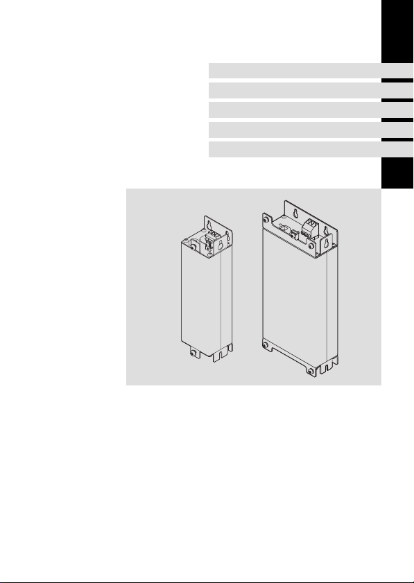
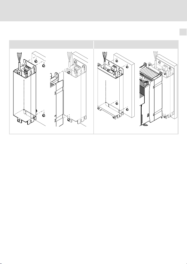
Lieferumfang
Pos. Beschreibung
Funk−Entstörfilter E84AZESRxxxxxx
0
Montageanleitung
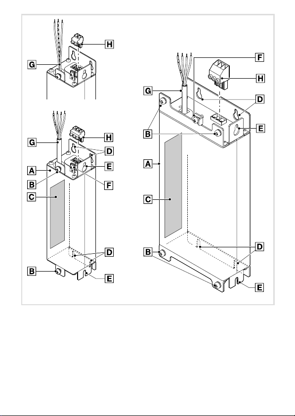
Elemente am Filter
Pos. Beschreibung
Funk−Entstörfilter
0
Befestigung des Antriebsreglers bei Standardmontage
1
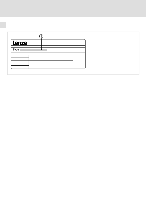
Typenschild
2
Befestigung Standardmontage (Unterbau−Montage)
3
Befestigung Montagevariante (Nebenbau−Montage)
4
PE−Anschluss
5
Anschlussleitung zum Antriebsregler
6
Netz−Anschlussklemme
7
0Abb. 0Tab. 0
Page 5

Inhalt i
1 Über diese Dokumentation 6. . . . . . . . . . . . . . . . . . . . . . . . . . . . . . . . . . . . . . . . . .
Dokumenthistorie 6. . . . . . . . . . . . . . . . . . . . . . . . . . . . . . . . . . . . . . . . . . . . . . . . . .
Verwendete Konventionen 7. . . . . . . . . . . . . . . . . . . . . . . . . . . . . . . . . . . . . . . . . .
Verwendete Hinweise 8. . . . . . . . . . . . . . . . . . . . . . . . . . . . . . . . . . . . . . . . . . . . . . .
2 Sicherheitshinweise 10. . . . . . . . . . . . . . . . . . . . . . . . . . . . . . . . . . . . . . . . . . . . . . . .
Restgefahren 10. . . . . . . . . . . . . . . . . . . . . . . . . . . . . . . . . . . . . . . . . . . . . . . . . . . . . .
3 Produktbeschreibung 12. . . . . . . . . . . . . . . . . . . . . . . . . . . . . . . . . . . . . . . . . . . . . . .
4 Technische Daten 15. . . . . . . . . . . . . . . . . . . . . . . . . . . . . . . . . . . . . . . . . . . . . . . . . .
Allgemeine Daten und Einsatzbedingungen 15. . . . . . . . . . . . . . . . . . . . . . . . . . .
Bemessungsdaten 17. . . . . . . . . . . . . . . . . . . . . . . . . . . . . . . . . . . . . . . . . . . . . . . . . .
Mechanische Daten 19. . . . . . . . . . . . . . . . . . . . . . . . . . . . . . . . . . . . . . . . . . . . . . .
5 Mechanische Installation 21. . . . . . . . . . . . . . . . . . . . . . . . . . . . . . . . . . . . . . . . . . . .
Standardmontage 22. . . . . . . . . . . . . . . . . . . . . . . . . . . . . . . . . . . . . . . . . . . . . . . . .
Montagevariante 24. . . . . . . . . . . . . . . . . . . . . . . . . . . . . . . . . . . . . . . . . . . . . . . . . .
6 Elektrische Installation 26. . . . . . . . . . . . . . . . . . . . . . . . . . . . . . . . . . . . . . . . . . . . . .
Wichtige Hinweise 26. . . . . . . . . . . . . . . . . . . . . . . . . . . . . . . . . . . . . . . . . . . . . . . . .
Anschlussplan 29. . . . . . . . . . . . . . . . . . . . . . . . . . . . . . . . . . . . . . . . . . . . . . . . . . . . .
Anschlussdaten 30. . . . . . . . . . . . . . . . . . . . . . . . . . . . . . . . . . . . . . . . . . . . . . . . . . . .
Montageschritte 32. . . . . . . . . . . . . . . . . . . . . . . . . . . . . . . . . . . . . . . . . . . . . . . . . . .
EDK84AZESRx DE/EN/FR/ES/IT 2.0
l
5
Page 6

1 Über diese Dokumentation
Dokumenthistorie
1 Über diese Dokumentation
Informationen zur Gültigkeit
Diese Anleitung ist gültig für
ƒ Funk−Entstörfilter E84AZESRxxxxLD
ƒ Funk−Entstörfilter E84AZESRxxxxLL
ƒ Funk−Entstörfilter E84AZESRxxxxSD
Zielgruppe
Diese Dokumentation richtet sich an qualifiziertes Fachpersonal nach IEC 60364.
Qualifiziertes Fachpersonal sind Personen, die für die auszuführenden Tätigkeiten bei der
Aufstellung, Montage, Inbetriebsetzung und dem Betrieb des Produkts über entsprechende
Qualifikationen verfügen.
I Tipp!
Informationen und Hilfsmittel rund um die Lenze−Produkte finden Sie im
Download−Bereich unter
http://www.Lenze.com
Dokumenthistorie
Materialnummer Version Beschreibung
.H:l 2.0 11/2011 TD00 Ergänzt:
13313390 1.0 08/2009 TD29 Erstausgabe
E84AZESR3024SD
E84AZESR3024LD
E84AZESR1534SD
6
l
EDK84AZESRx DE/EN/FR/ES/IT 2.0
Page 7
Über diese Dokumentation
Verwendete Konventionen
Verwendete Konventionen
Informationsart Auszeichnung Beispiele/Hinweise
Zahlenschreibweise
Dezimaltrennzeichen
Warnhinweise
UL−Warnhinweise
UR−Warnhinweise
Textauszeichnung
Programmname » « PC−Software
Symbole
Seitenverweis
Punkt Es wird generell der Dezimalpunkt
J
O
^
verwendet.
Zum Beispiel: 1234.56
Werden nur in der englischen Sprache
verwendet.
Zum Beispiel: »Engineer«, »Global
Drive Control« (GDC)
Verweis auf eine andere Seite mit zusätzlichen Informationen
Zum Beispiel:
^ 16 = siehe Seite 16
1
EDK84AZESRx DE/EN/FR/ES/IT 2.0
l
7
Page 8

1 Über diese Dokumentation
Verwendete Hinweise
Verwendete Hinweise
Um auf Gefahren und wichtige Informationen hinzuweisen, werden in dieser Dokumentation folgende Piktogramme und Signalwörter verwendet:
Sicherheitshinweise
Aufbau der Sicherheitshinweise:
} Gefahr!
(kennzeichnet die Art und die Schwere der Gefahr)
Hinweistext
(beschreibt die Gefahr und gibt Hinweise, wie sie vermieden werden kann)
Piktogramm und Signalwort Bedeutung
Gefahr von Personenschäden durch gefährliche elektrische Spannung
{ Gefahr!
} Gefahr!
( Stop!
Hinweis auf eine unmittelbar drohende Gefahr, die den
Tod oder schwere Verletzungen zur Folge haben kann,
wenn nicht die entsprechenden Maßnahmen getroffen
werden.
Gefahr von Personenschäden durch eine allgemeine Gefahrenquelle
Hinweis auf eine unmittelbar drohende Gefahr, die den
Tod oder schwere Verletzungen zur Folge haben kann,
wenn nicht die entsprechenden Maßnahmen getroffen
werden.
Gefahr von Sachschäden
Hinweis auf eine mögliche Gefahr, die Sachschäden zur
Folge haben kann, wenn nicht die entsprechenden Maßnahmen getroffen werden.
8
l
EDK84AZESRx DE/EN/FR/ES/IT 2.0
Page 9

Anwendungshinweise
Piktogramm und Signalwort Bedeutung
Über diese Dokumentation
Verwendete Hinweise
1
) Hinweis!
I Tipp!
,
Spezielle Sicherheitshinweise und Anwendungshinweise für UL und UR
Piktogramm und Signalwort Bedeutung
J Warnings!
O Warnings!
Wichtiger Hinweis für die störungsfreie Funktion
Nützlicher Tipp für die einfache Handhabung
Verweis auf andere Dokumentation
Sicherheitshinweis oder Anwendungshinweis für den
Betrieb eines UL−approbierten Geräts in UL−approbierten
Anlagen.
Möglicherweise wird das Antriebssystem nicht UL−gerecht betrieben, wenn nicht die entsprechenden Maßnahmen getroffen werden.
Sicherheitshinweis oder Anwendungshinweis für den
Betrieb eines UR−approbierten Geräts in UL−approbierten
Anlagen.
Möglicherweise wird das Antriebssystem nicht UL−gerecht betrieben, wenn nicht die entsprechenden Maßnahmen getroffen werden.
EDK84AZESRx DE/EN/FR/ES/IT 2.0
l
9
Page 10

2 Sicherheitshinweise
Restgefahren
2 Sicherheitshinweise
Restgefahren
{ Gefahr!
Gefährliche elektrische Spannung
Alle Leistungsanschlüsse führen bis zu 3 Minuten nach Netz−Ausschalten
gefährliche elektrische Spannung.
Mögliche Folgen:
ƒ Tod oder schwere Verletzungen beim Berühren der Leistungsanschlüsse.
Schutzmaßnahmen:
ƒ Vor Arbeiten an den Leistungsanschlüssen Netz abschalten und
mindestens 3 Minuten warten.
ƒ Prüfen, ob alle Leistungsanschlüsse spannungsfrei sind.
10
l
EDK84AZESRx DE/EN/FR/ES/IT 2.0
Page 11

Sicherheitshinweise
Restgefahren
O Warnings!
Conditions of Acceptability:
ƒ Appliance filters inherently have considerable leakage current to the
grounding conductor. The leakage current is to be measured in the end
product to determine compliance with the end use requirements.
ƒ The filters shall be provided with an overall enclosure suitable for the
applicable end product requirements. Mounting means should be
considered in the end use application.
ƒ These filters have been judged on the basis of the required spacings in the
Standard for Electromagnetic Interference Filters, UL 1283, Fifth Edition.
ƒ The suitablity of the grounding means in conjuction with the filter, shall be
evaluated in the end use product.
ƒ Electrical spacings between uninsulated dead metal parts should be in
accordance with the end use application.
ƒ The components were submitted and tested with a maximum
manufacturer’s recommended ambient 45°C as indicated. Suitability of
these devices for use in a higher ambient needs to be determined in the
end use application.
ƒ The suitability of filter leads, strain relief and lead terminations shall be
considered in the end use application.
ƒ The Abnormal Operation Test (Par. 32, UL 1283), (limited short circuit test)
was not conducted. Suitability of this device to comply with this
requirement shall be considered in the end use application.
2
EDK84AZESRx DE/EN/FR/ES/IT 2.0
l
11
Page 12
3 Produktbeschreibung
3 Produktbeschreibung
Identifikation
E84ZESR009
12
l
EDK84AZESRx DE/EN/FR/ES/IT 2.0
Page 13
Produktbeschreibung 3
Typenschlüssel E84 A ZES x xxx x xx
Produktreihe
Gerätegeneration
Zubehör
Filtertyp
R = Funk−Entstörfilter
M = Netzfilter
Maximale Leistung des Grundgeräts
z. B. 751 = 75 × 10
z. B. 222 = 22 × 102 = 2.2 kW
Netzspannung
2 = 1/PE AC 230 V
4 = 3/PE AC 400 V
Variante
LL = Low leakage
SD = Short distance
LD = Long distance
LDN001 = Long distance für erh. Bemessungsleistung
1
= 0.75 kW
Einsetzbarkeit
Die Verwendung dieses Filters ist zulässig mit Geräten der Produktreihe 8400 ab der Typenschildbezeichnung:
EDK84AZESRx DE/EN/FR/ES/IT 2.0
l
13
Page 14

3 Produktbeschreibung
Typ Hardware−Stand Typ Hardware−Stand
E84AVxxx2512
E84AVxxx3712
E84AVxxx7512
E84AVxxx1522
E84AVxxx2222
E84AVxxx3714
E84AVxxx5514
E84AVxxx7514
VA
Zuordnung Filter ˘ Grundgerät
Funk−Entstörfilter Antriebsregler
Typ Gerätegröße Typ Gerätegröße
E84AZESR3712LL
E84AZESR3712SD
E84AZESR3712LD
E84AZESR7512LL
E84AZESR7512SD
E84AZESR7512LD
E84AZESR2222LL
E84AZESR2222SD
E84AZESR2222LD
E84AZESR7514SD
E84AZESR7514LD
E84AZESR2224SD
E84AZESR2224LD
E84AZESR3024SD
E84AZESR3024LD
E84AZESR5524SD
E84AZESR5524LD
E84AZESR1534SD
E84AZESR1534LD
GG1
GG2
GG3
GG2
GG3
GG3 E84AVxxx3024xxS GG3
GG4
GG5
E84AVxxx1524
E84AVxxx2224
E84AVxxx3024
E84AVxxx4024
E84AVxxx5524
E84AVxxx7524
E84AVxxx1134
E84AVxxx1534
E84AVxxx2512
E84AVxxx3712
E84AVxxx5512
E84AVxxx7512
E84AVxxx1122
E84AVxxx1522
E84AVxxx2222
E84AVxxx3714
E84AVxxx5514
E84AVxxx7514
E84AVxxx1124
E84AVxxx1524
E84AVxxx2224
E84AVxxx3024xx0
E84AVxxx4024
E84AVxxx5524
E84AVxxx7524
E84AVxxx1134
E84AVxxx1534
VA
GG1
GG2
GG3
GG2
GG3
GG4
GG5
14
l
EDK84AZESRx DE/EN/FR/ES/IT 2.0
Page 15

Allgemeine Daten und Einsatzbedingungen
4 Technische Daten
Allgemeine Daten und Einsatzbedingungen
Allgemeine Daten
Normen
Approbation
Personenschutz und Geräteschutz
Schutzart
Isolationsfestigkeit EN 61800−5−1
UL 1283 Standard for Electromagnetic Interference Filters
EN 60529
NEMA 250 Berührschutz nach
(File No. E70122) for USA and Canada
IP20 Nicht im Anschlussbe-
Typ 1
< 2000 m Aufstellhöhe: Überspannungskategorie III
> 2000 m Aufstellhöhe: Überspannungskategorie II
Technische Daten
reich der Klemmen
4
EDK84AZESRx DE/EN/FR/ES/IT 2.0
l
15
Page 16
4 Technische Daten
Allgemeine Daten und Einsatzbedingungen
Einsatzbedingungen
Umgebungsbedingungen
Klimatisch
Lagerung IEC/EN 60721−3−1 1K3 (−25 ... +55 °C)
Transport IEC/EN 60721−3−2 2K3 (−25 ... +70 °C)
Betrieb IEC/EN 60721−3−3 3K3 (−10 ... +55 °C)
Feuchtebeanspruchung
Verschmutzung EN 61800−5−1 Verschmutzungsgrad 2
Aufstellhöhe < 4000 m üNN
Mechanisch
Rüttelfestigkeit (9.81 m/s2 = 1 g)
Transport
Betrieb
Elektrisch
Netzanschluss
Netzsystem
TT, TN (mit geerdetem Stern-
IT Betrieb nicht zulässig.
EN 61800−2 Feuchteklasse 3K3 (ohne Betauung; mittlere re-
IEC/EN 60721−3−2 2M2
EN 61800−5−1
Germanischer Lloyd 5 ... 13.2 Hz: Amplitude ±1 mm
EN 61800−5−1
punkt)
lative Feuchte 85 %)
> 1000 m üNN die Leistung um 5 %/1000 m reduzieren.
2 ... 9 Hz: Amplitude 3.5 mm
10 ... 200 Hz: beschleunigungsfest bis 10 m/s
200 ... 500 Hz: beschleunigungsfest bis 15 m/s
13.2 ... 100 Hz: beschleunigungsfest bis 0.7 g
10 ... 57 Hz: Amplitude 0.075 mm
57 ... 150 Hz: beschleunigungsfest bis 10 m/s
Betrieb uneingeschränkt erlaubt.
2
2
2
Montagebedingungen
Einbauort
Einbaulage Vertikal
Einbaufreiräume ^ 21
16
Im Schaltschrank
l
EDK84AZESRx DE/EN/FR/ES/IT 2.0
Page 17
Technische Daten
Bemessungsdaten
Bemessungsdaten
Grundlage der Daten
Spannung Spannungsbereich Frequenzbereich
Netz U
1/PE AC 230 180 − 0 % ... 264 + 0 % 45 ... 65
3/PE AC 400/500 320 − 0 % ... 550 + 0 % 45 ... 65
[V] U
LN
[V] f [Hz]
LN
4
Spannung Frequenz
Typ [V] [Hz] [A] [A]
E84AZESR3712xx 230 50/60 5.0 3.5 1
E84AZESR7512xx 230 50/60 9.0 6.5 1
E84AZESR2222xx 230 50/60 22 16.5 1
E84AZESR7514xx 400 50/60 3.3 2.4 3
E84AZESR2224xx 400 50/60 7.3 5.4 3
E84AZESR3024xx 400 50/60 9.8 5.4 3
E84AZESR5524xx 400 50/60 18 13.5 3
E84AZESR1534xx 400 50/60 29 21.8 3
max.
+45 °C
Strom
max.
+55 °C
Phasenzahl
Temperatur im Schaltschrank
EDK84AZESRx DE/EN/FR/ES/IT 2.0
l
17
Page 18
4 Technische Daten
Bemessungsdaten
Verlustleistung Verlustleistung
Typ PV [W] Typ PV [W]
E84AZESR3712LL 2.1 E84AZESR7514SD 1.5
E84AZESR3712SD 1.7 E84AZESR7514LD 1.5
E84AZESR3712LD 2.3 E84AZESR2224SD 7.4
E84AZESR7512LL 6.7 E84AZESR2224LD 7.2
E84AZESR7512SD 5.5 E84AZESR3024SD 11.8
E84AZESR7512LD 7.5 E84AZESR3024LD 9.7
E84AZESR2222LL 14.1 E84AZESR5524SD 25.0
E84AZESR2222SD 14.1 E84AZESR5524LD 14.0
E84AZESR2222LD 8.7 E84AZESR1534SD 24.0
E84AZESR1534LD 30.0
18
l
EDK84AZESRx DE/EN/FR/ES/IT 2.0
Page 19
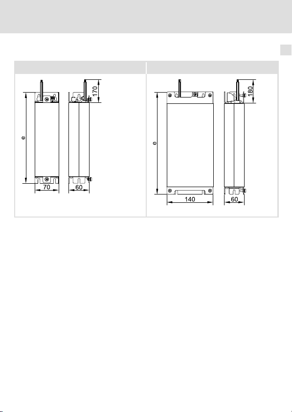
Technische Daten
Mechanische Daten
Gerätegröße GG1 − GG3 Gerätegröße GG4 − GG5
E84ZESR103 E84ZESR104
Alle Maße in Millimeter.
Mechanische Daten
4
EDK84AZESRx DE/EN/FR/ES/IT 2.0
l
19
Page 20
4 Technische Daten
Mechanische Daten
e
[mm] [kg]
E84AZESR3712xx 212 0.8
E84AZESR7512xx
E84AZESR7514xx 1.1
E84AZESR2222LL
E84AZESR2222SD 1.6
E84AZESR2222LD 1.3
E84AZESR2224SD 1.4
E84AZESR2224LD 1.2
E84AZESR3024SD 1.5
E84AZESR3024LD 1.3
E84AZESR5524SD
E84AZESR5524LD 2.4
E84AZESR1534SD
E84AZESR1534LD 3.3
262
317
306
361
1.0
1.6
3.1
2.9
20
l
EDK84AZESRx DE/EN/FR/ES/IT 2.0
Page 21

Mechanische Installation 5
5 Mechanische Installation
) Hinweis!
Das Filter kann in zwei Varianten montiert werden. Dadurch ergeben sich
unterschiedliche Einbaumaße.
ƒ Standardmontage: Das Filter wird unter das Grundgerät montiert.
ƒ Nebenbau−Montage: Bei geringer Schaltschranktiefe wird das Filter um 90°
gedreht, links neben das Grundgerät montiert.
EDK84AZESRx DE/EN/FR/ES/IT 2.0
l
21
Page 22
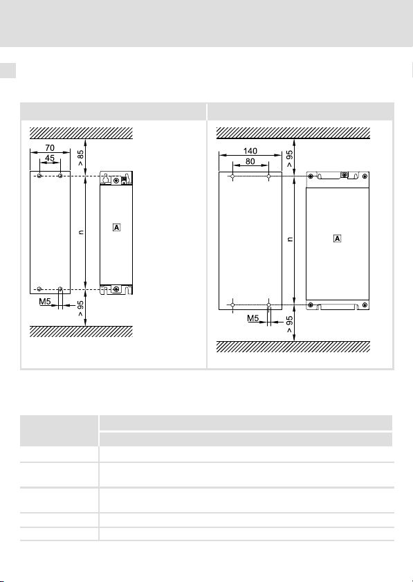
5 Mechanische Installation
Standardmontage
Standardmontage
Bohrplan
Gerätegröße GG1 − GG3 Gerätegröße GG4 − GG5
E84AZESR010 E84AZESR022
Alle Maße in Millimeter.
Unterbaufilter
0
n
[mm]
E84AZESR3712xx 190
E84AZESR7512xx
E84AZESR7514xx
E84AZESR2222xx
E84AZESR2224xx
E84AZESR5524xx 285
E84AZESR1534xx 340
240
295
22
l
EDK84AZESRx DE/EN/FR/ES/IT 2.0
Page 23
Mechanische Installation
Standardmontage
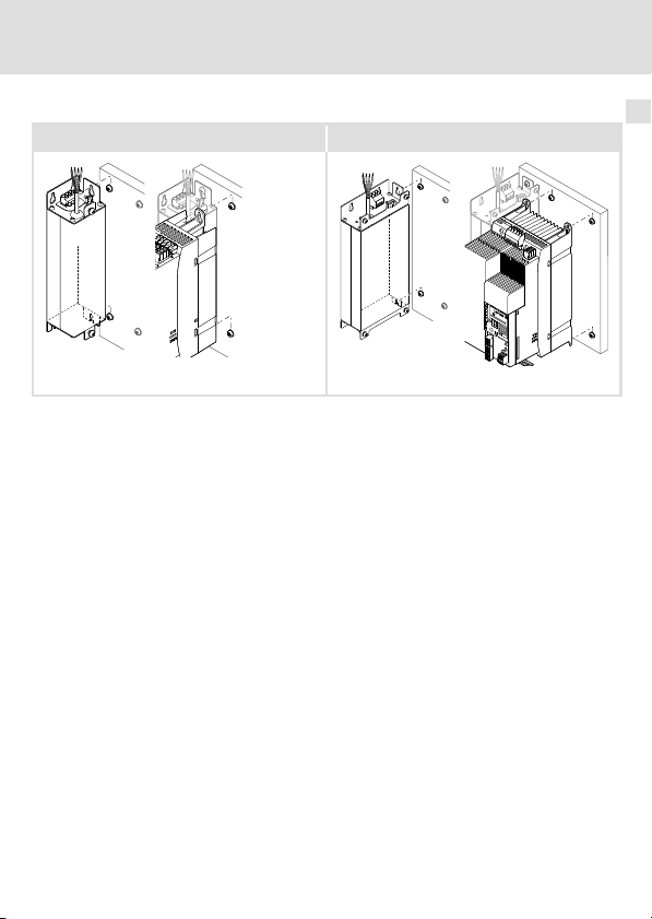
Montageschritte
Gerätegröße GG1 − GG3 Gerätegröße GG4 − GG5
E84AZESR007 E84AZESR020
So gehen Sie bei der Montage vor:
1. Bereiten Sie auf der Montageplatte M5−Gewindebohrungen vor und bestücken Sie
diese mit Schrauben und Unterlegscheiben.
– Vier Kombischrauben M5 oder Innensechskantschrauben M5 mit
Unterlegscheiben verwenden.
– Schrauben noch nicht ganz eindrehen.
2. Montieren Sie das Filter auf die vorbereitete Montageplatte.
– Schrauben vorerst nur handfest anziehen.
3. Lösen Sie die beiden Kombischrauben für die Befestigung des Grundgerätes auf dem
Filter.
– Zwei Kombischrauben M5 × 14 mm.
4. Montieren Sie das Grundgerät auf das Filter und ziehen Sie die Schrauben fest an.
– Beachten Sie dabei die Hinweise in der Dokumentation zum Grundgerät.
– Anzugsmoment: 3.4 Nm (30 lb−in)
5. Montieren Sie ggf. weitere Einheiten vor.
6. Richten Sie alle Einheiten miteinander aus.
7. Schrauben Sie alle Einheiten auf der Montageplatte fest.
– Anzugsmoment: 3.4 Nm (30 lb−in)
5
EDK84AZESRx DE/EN/FR/ES/IT 2.0
l
23
Page 24
5 Mechanische Installation
Montagevariante
Montagevariante
Bohrplan
Gerätegröße GG1 − GG3 Gerätegröße GG4 − GG5
E84AZESR011 E84AZESR023
Alle Maße in Millimeter.
Nebenbaufilter
0
Grundgerät
1
n n1
[mm]
E84AZESR3712xx 190 180
E84AZESR7512xx
E84AZESR7514xx
E84AZESR2222xx
E84AZESR2224xx
E84AZESR5524xx 285 285
E84AZESR1534xx 340 340
240 230
295 285
24
l
EDK84AZESRx DE/EN/FR/ES/IT 2.0
Page 25
Mechanische Installation
Montagevariante
Montageschritte
Gerätegröße GG1 − GG3 Gerätegröße GG4 − GG5
E84AZESR008 E84AZESR021
So gehen Sie bei der Montage vor:
1. Bereiten Sie auf der Montageplatte Gewindebohrungen M5 vor und bestücken Sie
diese mit Schrauben und Unterlegscheiben.
– Für Filter zwei Kombischrauben M5 oder Innensechskantschrauben M5 mit
Unterlegscheiben.
– Für Grundgerät zwei Kombischrauben M5 oder Innensechskantschrauben M5 mit
Unterlegscheiben.
– Schrauben noch nicht ganz eindrehen.
2. Entfernen Sie am Filter die beiden Kombischrauben zur Befestigung des
Grundgerätes
3. Montieren Sie das Filter auf der vorbereiteten Montageplatte.
– Schrauben vorerst nur handfest anziehen.
4. Montieren Sie das Grundgerät auf der vorbereiteten Montageplatte.
– Beachten Sie dabei die Hinweise in der Dokumentation zum Grundgerät.
– Schrauben vorerst nur handfest anziehen.
5. Montieren Sie ggf. weitere Einheiten vor.
6. Richten Sie alle Einheiten miteinander aus.
7. Schrauben Sie alle Einheiten auf der Montageplatte fest.
– Anzugsmoment: 3.4 Nm (30 lb−in)
5
EDK84AZESRx DE/EN/FR/ES/IT 2.0
l
25
Page 26

6 Elektrische Installation
Wichtige Hinweise
6 Elektrische Installation
Wichtige Hinweise
{ Gefahr!
Gefährliche elektrische Spannung
Alle Leistungsanschlüsse führen bis zu 3 Minuten nach Netz−Ausschalten
gefährliche elektrische Spannung.
Mögliche Folgen:
ƒ Tod oder schwere Verletzungen beim Berühren der Leistungsanschlüsse.
Schutzmaßnahmen:
ƒ Vor Arbeiten an den Leistungsanschlüssen Netz abschalten und
mindestens 3 Minuten warten.
ƒ Prüfen, ob alle Leistungsanschlüsse spannungsfrei sind.
{ Gefahr!
Gefährliche elektrische Spannung
Bei den Varianten E84AZESxxxxxSD und E84AZESxxxxxLD beträgt der
Ableitstrom gegen Erde (PE) > 3.5 mA AC bzw. > 10 mA DC.
Mögliche Folgen:
ƒ Tod oder schwere Verletzungen beim Berühren des Gerätes im Fehlerfall.
Schutzmaßnahmen:
ƒ Die in der EN 61800−5−1 geforderten Maßnahmen umsetzen.
Insbesondere:
– Festinstallation
– PE−Anschluss normgerecht ausführen (PE−Leiterdurchmesser ³ 10 mm
oder PE−Leiter doppelt auflegen)
2
26
l
EDK84AZESRx DE/EN/FR/ES/IT 2.0
Page 27

Elektrische Installation
Wichtige Hinweise
( Stop!
Kein Geräteschutz gegen zu hohe Netzspannung
Der Netzeingang ist intern nicht abgesichert.
Mögliche Folgen:
ƒ Zerstörung des Gerätes bei zu hoher Netzspannung.
Schutzmaßnahmen:
ƒ Beachten Sie die maximal zulässige Netzspannung.
ƒ Sichern Sie das Gerät netzseitig fachgerecht gegen Netzschwankungen
und Spannungsspitzen ab.
6
EDK84AZESRx DE/EN/FR/ES/IT 2.0
l
27
Page 28
6 Elektrische Installation
Wichtige Hinweise
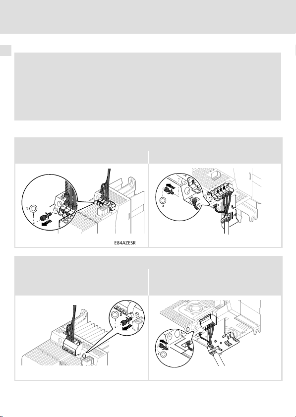
) Hinweis!
Beim Einsatz der Filtertypen E84AZESRxxxxLL oder E84AZESRxxxxSD sind
besondere Maßnahmen erforderlich:
Entfernen Sie am Grundgerät jeweils netzseitig und motorseitig die
Kontaktschraube für die erdseitige Funkentstörung, damit die zugesicherten
Eigenschaften der Grundgerät−Filter−Kombination eingehalten werden.
So entfernen Sie die Kontaktschraube:
Gerätegröße GG1 − GG3
netzseitig motorseitig
E84AZESR006 E84AZESR014
Gerätegröße GG4 − GG5
netzseitig motorseitig
(nicht mit E84AZESR1534SD)
28
E84AZESR055 E84AZESR060
l
EDK84AZESRx DE/EN/FR/ES/IT 2.0
Page 29
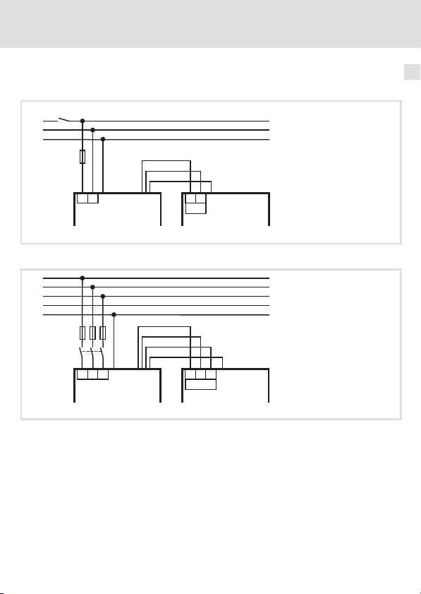
Anschlussplan
ƒ 1 N/PE AC 230 V:
K1
L1
N
PE
F1
L1
E84AZESRxxxxxx E84AVxxxxxx
ƒ 3 /PE AC 400 V:
L1
L2
L3
N
PE
F1...F3
K1
L1
E84AZESxxxxxxx E84AVxxxxxx
L' (BK)
N' (BK)
PE (GN/YE)
PE PE
L3 L3
PE PE
L1NN
X100
L1' (BK)
L2' (BK)
L3' (BK)
PE (GN/YE)
L1L2 L2
X100
Elektrische Installation
Anschlussplan
8400GG032
8400GG033
6
EDK84AZESRx DE/EN/FR/ES/IT 2.0
l
29
Page 30

6 Elektrische Installation
Anschlussdaten
Anschlussdaten
ƒ 1 N/PE AC 230 V:
Netz−Anschlussklemme Beschreibung
Gerätegröße GG1 − GG3
L1NAnschluss der Netzphase und des Null-
+
E84ZESR013
leiters.
Anschluss des netzseitigen Schutzleiters.
L1, N
[mm2]
[AWG]
E84AZESR3712xx
E84AZESR7512xx
E84AZESR2222xx
Anschlussleitung zum Antriebsregler Beschreibung
Gerätegröße GG1 − GG3
e84ZESR012
1 2.5
18 12
1 6
18 10
30
[Nm]
[mm] [mm2]
[lb−in]
0.5
4.4
0.5
4.4
7
8
L1’N’Filter−Ausgangsleiter (Litze mit Ade-
rendhülsen, Farbe BK).
Ausgangsseitiger Schutzleiter (Litze mit
PE
Aderendhülse, Farbe GN/YE).
l
PE/+
[AWG]
1 2.5
18 12
1 6
18 10
[Nm]
[lb−in]
1.7
15
1.7
15
EDK84AZESRx DE/EN/FR/ES/IT 2.0
[mm]
10
10
Page 31

Elektrische Installation
ƒ 3 /PE AC 400 V:
Netz−Anschlussklemme Beschreibung
Gerätegröße GG1 − GG3 Gerätegröße GG4 − GG5
L1
Anschluss der Netzphasen.
L2
L3
Anschluss des netzseitigen Schutzlei-
+
ters.
E84ZESR015 E84ZESR026
Anschlussdaten
6
L1, L2, L3
[mm2]
[AWG]
E84AZESR7514xx
E84AZESR2224xx
E84AZESR5524xx
E84AZESR1534xx
Anschlussleitung zum Antriebsregler Beschreibung
Gerätegröße GG1 − GG3 Gerätegröße GG4 − GG5
e84ZESR014 e84ZESR027
EDK84AZESRx DE/EN/FR/ES/IT 2.0
1 2.5
18 12
1 6
18 10
1 ... 16
18 ... 6
[Nm]
[mm] [mm2]
[lb−in]
0.5
4.4
0.5
4.4
2.0
17.7
7
10
10
L1’
Filter−Ausgangsleiter (Litze mit Ader-
endhülsen, Farbe BK).
L2’
L3’
PE Ausgangsseitiger Schutzleiter (Litze mit
Aderendhülse, Farbe GN/YE).
l
[AWG]
1 2.5
18 12
1 6
18 10
1 ... 4
18 ... 12
PE/+
[Nm]
[lb−in]
17.7
17.7
[mm]
1.7
2.0
2.0
10
15
10
10
31
Page 32

6 Elektrische Installation
Montageschritte
Montageschritte
So schließen Sie das Filter an:
1. Filter−Ausgangsleitung an die Klemmenleiste X100 am Grundgerät anschließen.
2. Netzleitung an die Netz−Anschlussklemme des Filters anschließen.
3. Netzseitigen Schutzleiter an Schutzleiter−Schraube montieren.
– Der PE−Anschluss muss nach EN 61800−5−1 ausgeführt werden.
32
l
EDK84AZESRx DE/EN/FR/ES/IT 2.0
Page 33

Elektrische Installation
Montageschritte
6
EDK84AZESRx DE/EN/FR/ES/IT 2.0
l
33
Page 34

Scope of supply
Pos. Description
RFI filters E84AZESRxxxxxx
0
Mounting Instructions
Elements on the filter
Pos. Description
RFI filter
0
Fastening of the controller in case of standard mounting
1
Nameplate
2
Fastening in case of standard mounting (footprint mounting)
3
Fastening in case of a mounting variant (side−by−side mounting)
4
PE connection
5
Connecting cable to the controller
6
Mains terminal
7
0Abb. 0Tab. 0
Page 35

Contents i
1 About this documentation 36. . . . . . . . . . . . . . . . . . . . . . . . . . . . . . . . . . . . . . . . . . .
Document history 36. . . . . . . . . . . . . . . . . . . . . . . . . . . . . . . . . . . . . . . . . . . . . . . . . .
Conventions used 37. . . . . . . . . . . . . . . . . . . . . . . . . . . . . . . . . . . . . . . . . . . . . . . . . .
Notes used 38. . . . . . . . . . . . . . . . . . . . . . . . . . . . . . . . . . . . . . . . . . . . . . . . . . . . . . . .
2 Safety instructions 40. . . . . . . . . . . . . . . . . . . . . . . . . . . . . . . . . . . . . . . . . . . . . . . . .
Residual hazards 40. . . . . . . . . . . . . . . . . . . . . . . . . . . . . . . . . . . . . . . . . . . . . . . . . . .
3 Product description 42. . . . . . . . . . . . . . . . . . . . . . . . . . . . . . . . . . . . . . . . . . . . . . . . .
4 Technical data 45. . . . . . . . . . . . . . . . . . . . . . . . . . . . . . . . . . . . . . . . . . . . . . . . . . . . .
General data and operating conditions 45. . . . . . . . . . . . . . . . . . . . . . . . . . . . . . .
Rated data 47. . . . . . . . . . . . . . . . . . . . . . . . . . . . . . . . . . . . . . . . . . . . . . . . . . . . . . . .
Mechanical data 49. . . . . . . . . . . . . . . . . . . . . . . . . . . . . . . . . . . . . . . . . . . . . . . . . .
5 Mechanical installation 51. . . . . . . . . . . . . . . . . . . . . . . . . . . . . . . . . . . . . . . . . . . . .
Standard mounting 52. . . . . . . . . . . . . . . . . . . . . . . . . . . . . . . . . . . . . . . . . . . . . . . . .
Mounting variant 54. . . . . . . . . . . . . . . . . . . . . . . . . . . . . . . . . . . . . . . . . . . . . . . . . .
6 Electrical installation 56. . . . . . . . . . . . . . . . . . . . . . . . . . . . . . . . . . . . . . . . . . . . . . .
Important notes 56. . . . . . . . . . . . . . . . . . . . . . . . . . . . . . . . . . . . . . . . . . . . . . . . . . .
Connection plan 59. . . . . . . . . . . . . . . . . . . . . . . . . . . . . . . . . . . . . . . . . . . . . . . . . . .
Connection data 60. . . . . . . . . . . . . . . . . . . . . . . . . . . . . . . . . . . . . . . . . . . . . . . . . . .
Mounting steps 62. . . . . . . . . . . . . . . . . . . . . . . . . . . . . . . . . . . . . . . . . . . . . . . . . . . .
EDK84AZESRx DE/EN/FR/ES/IT 2.0
l
35
Page 36

1 About this documentation
Document history
1 About this documentation
Validity information
These instructions are valid for
ƒ RFI filter E84AZESRxxxxLD
ƒ RFI filter E84AZESRxxxxLL
ƒ RFI filter E84AZESRxxxxSD
Target group
This documentation is directed at qualified skilled personnel according to IEC 60364.
Qualified skilled personnel are persons who have the required qualifications to carry out all
activities involved in installing, mounting, commissioning, and operating the product.
I Tip!
Information and auxiliary devices around the Lenze products can be found in
the download area at
http://www.Lenze.com
Document history
Material number Version Description
.H:l 2.0 11/2011 TD00 Supplemented:
13313390 1.0 08/2009 TD29 First edition
E84AZESR3024SD
E84AZESR3024LD
E84AZESR1534SD
36
l
EDK84AZESRx DE/EN/FR/ES/IT 2.0
Page 37

About this documentation
Conventions used
Conventions used
Type of information Identification Examples/notes
Spelling of numbers
Decimal separator
Warnings
UL warnings
UR warnings
Text
Program name » « PC software
Icons
Page reference
Point In general, the decimal point is used.
J
For instance: 1234.56
Are only given in English.
O
For example: »Engineer«, »Global
Drive Control« (GDC)
^
Reference to another page with
additional information
For instance: ^ 16 = see page 16
1
EDK84AZESRx DE/EN/FR/ES/IT 2.0
l
37
Page 38

1 About this documentation
Notes used
Notes used
The following pictographs and signal words are used in this documentation to indicate
dangers and important information:
Safety instructions
Structure of safety instructions:
} Danger!
(characterises the type and severity of danger)
Note
(describes the danger and gives information about how to prevent dangerous
situations)
Pictograph and signal word Meaning
Danger of personal injury through dangerous electrical
voltage.
{ Danger!
} Danger!
( Stop!
Reference to an imminent danger that may result in
death or serious personal injury if the corresponding
measures are not taken.
Danger of personal injury through a general source of
danger.
Reference to an imminent danger that may result in
death or serious personal injury if the corresponding
measures are not taken.
Danger of property damage.
Reference to a possible danger that may result in
property damage if the corresponding measures are not
taken.
38
l
EDK84AZESRx DE/EN/FR/ES/IT 2.0
Page 39

Application notes
Pictograph and signal word Meaning
About this documentation
Notes used
1
) Note!
I Tip!
,
Special safety instructions and application notes for UL and UR
Pictograph and signal word Meaning
J Warnings!
O Warnings!
Important note to ensure troublefree operation
Useful tip for simple handling
Reference to another documentation
Safety or application note for the operation of a
UL−approved device in UL−approved systems.
Possibly the drive system is not operated in compliance
with UL if the corresponding measures are not taken.
Safety or application note for the operation of a
UR−approved device in UL−approved systems.
Possibly the drive system is not operated in compliance
with UL if the corresponding measures are not taken.
EDK84AZESRx DE/EN/FR/ES/IT 2.0
l
39
Page 40

2 Safety instructions
Residual hazards
2 Safety instructions
Residual hazards
{ Danger!
Dangerous electrical voltage
All power terminals remain live for up to three minutes after mains
disconnection.
Possible consequences:
ƒ Death or severe injuries when touching the power terminals.
Protective measures:
ƒ Switch off the power supply and wait for at least three minutes before
working on the power terminals.
ƒ Make sure that all power terminals are deenergised.
40
l
EDK84AZESRx DE/EN/FR/ES/IT 2.0
Page 41

Safety instructions
Residual hazards
O Warnings!
Conditions of Acceptability:
ƒ Appliance filters inherently have considerable leakage current to the
grounding conductor. The leakage current is to be measured in the end
product to determine compliance with the end use requirements.
ƒ The filters shall be provided with an overall enclosure suitable for the
applicable end product requirements. Mounting means should be
considered in the end use application.
ƒ These filters have been judged on the basis of the required spacings in the
Standard for Electromagnetic Interference Filters, UL 1283, Fifth Edition.
ƒ The suitablity of the grounding means in conjuction with the filter, shall be
evaluated in the end use product.
ƒ Electrical spacings between uninsulated dead metal parts should be in
accordance with the end use application.
ƒ The components were submitted and tested with a maximum
manufacturer’s recommended ambient 45°C as indicated. Suitability of
these devices for use in a higher ambient needs to be determined in the
end use application.
ƒ The suitability of filter leads, strain relief and lead terminations shall be
considered in the end use application.
ƒ The Abnormal Operation Test (Par. 32, UL 1283), (limited short circuit test)
was not conducted. Suitability of this device to comply with this
requirement shall be considered in the end use application.
2
EDK84AZESRx DE/EN/FR/ES/IT 2.0
l
41
Page 42

3 Product description
3 Product description
Identification
E84ZESR009
42
l
EDK84AZESRx DE/EN/FR/ES/IT 2.0
Page 43

Product description 3
Type code E84 A ZES x xxx x xx
Product range
Version
Accessories
Filter type
R = RFI filter
M = Mains filter
Maximum power of the standard device
e.g. 751 = 75 × 10
e.g. 222 = 22 × 102 = 2.2 kW
Mains voltage
2 = 1/PE AC 230 V
4 = 3/PE AC 400 V
Variant
LL = Low leakage
SD = Short distance
LD = Long distance
LDN001 = Long distance for increased rated power
1
= 0.75 kW
Application range
This filter may be used together with the controllers of the 8400 product range from the
following nameplate data:
EDK84AZESRx DE/EN/FR/ES/IT 2.0
l
43
Page 44

3 Product description
Type Hardware version Type Hardware version
E84AVxxx2512
E84AVxxx3712
E84AVxxx7512
E84AVxxx1522
E84AVxxx2222
E84AVxxx3714
E84AVxxx5514
E84AVxxx7514
VA
Assignment of filters to standard devices
RFI filter Controller
Type Device size Type Device size
E84AZESR3712LL
E84AZESR3712SD
E84AZESR3712LD
E84AZESR7512LL
E84AZESR7512SD
E84AZESR7512LD
E84AZESR2222LL
E84AZESR2222SD
E84AZESR2222LD
E84AZESR7514SD
E84AZESR7514LD
E84AZESR2224SD
E84AZESR2224LD
E84AZESR3024SD
E84AZESR3024LD
E84AZESR5524SD
E84AZESR5524LD
E84AZESR1534SD
E84AZESR1534LD
GG1
GG2
GG3
GG2
GG3
GG3 E84AVxxx3024xxS GG3
GG4
GG5
E84AVxxx1524
E84AVxxx2224
E84AVxxx3024
E84AVxxx4024
E84AVxxx5524
E84AVxxx7524
E84AVxxx1134
E84AVxxx1534
E84AVxxx2512
E84AVxxx3712
E84AVxxx5512
E84AVxxx7512
E84AVxxx1122
E84AVxxx1522
E84AVxxx2222
E84AVxxx3714
E84AVxxx5514
E84AVxxx7514
E84AVxxx1124
E84AVxxx1524
E84AVxxx2224
E84AVxxx3024xx0
E84AVxxx4024
E84AVxxx5524
E84AVxxx7524
E84AVxxx1134
E84AVxxx1534
VA
GG1
GG2
GG3
GG2
GG3
GG4
GG5
44
l
EDK84AZESRx DE/EN/FR/ES/IT 2.0
Page 45

General data and operating conditions
4 Technical data
General data and operating conditions
General data
Standards
Approbation
Protection of persons and device protection
Enclosure
Insulation resistance EN 61800−5−1
UL 1283 Standard for Electromagnetic Interference Filters
EN 60529
NEMA 250 Protection against accidental contact according
Technical data
(File No. E70122) for USA and Canada
IP20 Not in the wire range
to type 1
< 2000 m site altitude: overvoltage category III
> 2000 m site altitude: overvoltage category II
of the terminals
4
EDK84AZESRx DE/EN/FR/ES/IT 2.0
l
45
Page 46

4 Technical data
General data and operating conditions
Operating conditions
Ambient conditions
Climatic
Storage IEC/EN 60721−3−1 1K3 (−25 ... +55 °C)
Transport IEC/EN 60721−3−2 2K3 (−25 ... +70 °C)
Operation IEC/EN 60721−3−3 3K3 (−10 ... +55 °C)
Permissible
humidity
Pollution EN 61800−5−1 Degree of pollution 2
Site altitude < 4000 m amsl
Mechanical
Vibration resistance (9.81 m/s2 = 1 g)
Transport
Operation
Electrical
Mains connection
Power system
TT, TN (with earthed neutral) Operation is permitted without any restrictions.
IT Operation is not permissible.
EN 61800−2 Humidity class 3K3 (without condensation;
IEC/EN 60721−3−2 2M2
EN 61800−5−1
Germanischer Lloyd 5 ... 13.2 Hz: amplitude ±1 mm
EN 61800−5−1
average relative humidity 85 %)
Above 1000 m amsl reduce the power by
5 %/ 1000 m.
2 ... 9 Hz: amplitude 3.5 mm
10 ... 200 Hz: acceleration resistant up to 10 m/s
200 ... 500 Hz: acceleration resistant up to
2
15 m/s
13.2 ... 100 Hz: acceleration resistant up to 0.7 g
10 ... 57 Hz: amplitude 0.075 mm
57 ... 150 Hz: acceleration resistant up to 10 m/s
2
2
Mounting conditions
Mounting place
Mounting position Vertical
Free space ^ 51
46
In the control cabinet
l
EDK84AZESRx DE/EN/FR/ES/IT 2.0
Page 47

Technical data
Rated data
Rated data
Basis of the data
Voltage Voltage range Frequency range
Mains V
1/PE AC 230 180 − 0 % ... 264 + 0 % 45 ... 65
3/PE AC 400/500 320 − 0 % ... 550 + 0 % 45 ... 65
[V] V
LN
[V] f [Hz]
LN
4
Voltage Frequency
Type [V] [Hz] [A] [A]
E84AZESR3712xx 230 50/60 5.0 3.5 1
E84AZESR7512xx 230 50/60 9.0 6.5 1
E84AZESR2222xx 230 50/60 22 16.5 1
E84AZESR7514xx 400 50/60 3.3 2.4 3
E84AZESR2224xx 400 50/60 7.3 5.4 3
E84AZESR3024xx 400 50/60 9.8 5.4 3
E84AZESR5524xx 400 50/60 18 13.5 3
E84AZESR1534xx 400 50/60 29 21.8 3
max.
+45 °C
Current
max.
+55 °C
Number of
Temperature in the control cabinet
EDK84AZESRx DE/EN/FR/ES/IT 2.0
l
phases
47
Page 48

4 Technical data
Rated data
Power loss Power loss
Type PV [W] Type PV [W]
E84AZESR3712LL 2.1 E84AZESR7514SD 1.5
E84AZESR3712SD 1.7 E84AZESR7514LD 1.5
E84AZESR3712LD 2.3 E84AZESR2224SD 7.4
E84AZESR7512LL 6.7 E84AZESR2224LD 7.2
E84AZESR7512SD 5.5 E84AZESR3024SD 11.8
E84AZESR7512LD 7.5 E84AZESR3024LD 9.7
E84AZESR2222LL 14.1 E84AZESR5524SD 25.0
E84AZESR2222SD 14.1 E84AZESR5524LD 14.0
E84AZESR2222LD 8.7 E84AZESR1534SD 24.0
E84AZESR1534LD 30.0
48
l
EDK84AZESRx DE/EN/FR/ES/IT 2.0
Page 49

Mechanical data
Device size GG1 − GG3 Device size GG4 − GG5
E84ZESR103 E84ZESR104
All dimensions in millimetres.
Technical data
Mechanical data
4
EDK84AZESRx DE/EN/FR/ES/IT 2.0
l
49
Page 50

4 Technical data
Mechanical data
e
[mm] [kg]
E84AZESR3712xx 212 0.8
E84AZESR7512xx
E84AZESR7514xx 1.1
E84AZESR2222LL
E84AZESR2222SD 1.6
E84AZESR2222LD 1.3
E84AZESR2224SD 1.4
E84AZESR2224LD 1.2
E84AZESR3024SD 1.5
E84AZESR3024LD 1.3
E84AZESR5524SD
E84AZESR5524LD 2.4
E84AZESR1534SD
E84AZESR1534LD 3.3
262
317
306
361
1.0
1.6
3.1
2.9
50
l
EDK84AZESRx DE/EN/FR/ES/IT 2.0
Page 51

Mechanical installation 5
5 Mechanical installation
) Note!
The filter can be mounted in two ways. From this result different mounting
dimensions.
ƒ Standard mounting: The filter is mounted underneath the standard device.
ƒ Side−by−side mounting: In case of a low depth of the control cabinet, the
filter is rotated by 90° and mounted to the left side of the standard device.
EDK84AZESRx DE/EN/FR/ES/IT 2.0
l
51
Page 52

5 Mechanical installation
Standard mounting
Standard mounting
Drilling pattern
Device size GG1 − GG3 Device size GG4 − GG5
E84AZESR010 E84AZESR022
All dimensions in millimetres.
Footprint filter
0
n
[mm]
E84AZESR3712xx 190
E84AZESR7512xx
E84AZESR7514xx
E84AZESR2222xx
E84AZESR2224xx
E84AZESR5524xx 285
E84AZESR1534xx 340
240
295
52
l
EDK84AZESRx DE/EN/FR/ES/IT 2.0
Page 53

Mechanical installation
Standard mounting
Mounting steps
Device size GG1 − GG3 Device size GG4 − GG5
E84AZESR007 E84AZESR020
Proceed as follows for installation:
1. Prepare M5 threaded holes on the mounting plate and equip them with screws and
washers.
– Use four M5 screw and washer assemblies or M5 hexagon socket screws with
washers.
– Do not yet tighten the screws.
2. Mount the filter onto the prepared mounting plate.
– Only tighten the screws hand−tight.
3. Loosen the two screw and washer assemblies to fix the standard device on the filter.
– Two M5 × 14 mm screw and washer assemblies.
4. Mount the standard device onto the filter and tighten the screws.
– Observe the instructions in the documentation for the standard device.
– Tightening torque: 3.4 Nm (30 lb−in)
5. If necessary, preassemble additional units.
6. Align all units.
7. Screw all units onto the mounting plate.
– Tightening torque: 3.4 Nm (30 lb−in)
5
EDK84AZESRx DE/EN/FR/ES/IT 2.0
l
53
Page 54

5 Mechanical installation
Mounting variant
Mounting variant
Drilling pattern
Device size GG1 − GG3 Device size GG4 − GG5
E84AZESR011 E84AZESR023
All dimensions in millimetres.
Side−by−side filter
0
Standard device
1
n n1
[mm]
E84AZESR3712xx 190 180
E84AZESR7512xx
E84AZESR7514xx
E84AZESR2222xx
E84AZESR2224xx
E84AZESR5524xx 285 285
E84AZESR1534xx 340 340
240 230
295 285
54
l
EDK84AZESRx DE/EN/FR/ES/IT 2.0
Page 55

Mechanical installation
Mounting variant
Mounting steps
Device size GG1 − GG3 Device size GG4 − GG5
E84AZESR008 E84AZESR021
Proceed as follows for installation:
1. Prepare M5 threaded holes on the mounting plate and equip them with screws and
washers.
– Two M5 screw and washer assemblies or M5 hexagon socket screws with washers
for the filter.
– Two M5 screw and washer assemblies or M5 hexagon socket screws with washers
for the standard device.
– Do not yet tighten the screws.
2. Remove the screw and washer assemblies from the filter to fix the standard device.
3. Mount the filter onto the prepared mounting plate.
– Only tighten the screws hand−tight.
4. Mount the standard device onto the prepared mounting plate.
– Observe the instructions in the documentation for the standard device.
– Only tighten the screws hand−tight.
5. If necessary, preassemble additional units.
6. Align all units.
7. Screw all units onto the mounting plate.
– Tightening torque: 3.4 Nm (30 lb−in)
5
EDK84AZESRx DE/EN/FR/ES/IT 2.0
l
55
Page 56

6 Electrical installation
Important notes
6 Electrical installation
Important notes
{ Danger!
Dangerous electrical voltage
All power terminals remain live for up to three minutes after mains
disconnection.
Possible consequences:
ƒ Death or severe injuries when touching the power terminals.
Protective measures:
ƒ Switch off the power supply and wait for at least three minutes before
working on the power terminals.
ƒ Make sure that all power terminals are deenergised.
{ Danger!
Hazardous electrical voltage
For the variants E84AZESxxxxxSDand E84AZESxxxxxLD the discharge current
to PE is > 3.5 mA AC or > 10 mA DC.
Possible consequences:
ƒ Death or severe injuries when touching the device in case of a fault.
Protective measures:
ƒ Implement the measures required in EN 61800−5−1, especially:
– Fixed installation
– The PE connection must comply with the standards (PE conductor
diameter ³ 10 mm
2
or use a double PE conductor)
56
l
EDK84AZESRx DE/EN/FR/ES/IT 2.0
Page 57

Electrical installation
Important notes
( Stop!
No device protection if the mains voltage is too high
The mains input is not internally fused.
Possible consequences:
ƒ Destruction of the device if the mains voltage is too high.
Protective measures:
ƒ Observe the maximally permissible mains voltage.
ƒ Fuse the device correctly on the supply side against mains fluctuations and
voltage peaks.
6
EDK84AZESRx DE/EN/FR/ES/IT 2.0
l
57
Page 58

6 Electrical installation
Important notes
) Note!
When the filter types E84AZESRxxxxLL or E84AZESRxxxxSD are used, special
measures are required:
Remove the contact screws for interference suppression on the supply side and
the motor side of the standard device to ensure the features of the standard
device/filter combination.
How to remove the contact screw:
Device size GG1 − GG3
supply side motor side
E84AZESR006 E84AZESR014
Device size GG4 − GG5
supply side motor side
(except with E84AZESR1534SD)
58
E84AZESR055 E84AZESR060
l
EDK84AZESRx DE/EN/FR/ES/IT 2.0
Page 59

Connection plan
ƒ 1 N/PE AC 230 V:
K1
L1
N
PE
F1
L1
E84AZESRxxxxxx E84AVxxxxxx
ƒ 3 /PE AC 400 V:
L1
L2
L3
N
PE
F1...F3
K1
L1
E84AZESxxxxxxx E84AVxxxxxx
L' (BK)
N' (BK)
PE (GN/YE)
PE PE
L3 L3
PE PE
L1NN
X100
L1' (BK)
L2' (BK)
L3' (BK)
PE (GN/YE)
L1L2 L2
X100
Electrical installation
Connection plan
8400GG032
8400GG033
6
EDK84AZESRx DE/EN/FR/ES/IT 2.0
l
59
Page 60

6 Electrical installation
Connection data
Connection data
ƒ 1 N/PE AC 230 V:
Netz−Anschlussklemme Beschreibung
Device size GG1 − GG3
L1NAnschluss der Netzphase und des
+
E84ZESR013
Nullleiters.
Anschluss des netzseitigen
Schutzleiters.
L1, N
[mm2]
[AWG]
E84AZESR3712xx
E84AZESR7512xx
E84AZESR2222xx
Connecting cable to the controller Description
Device size GG1 − GG3
e84ZESR012
1 2.5
18 12
1 6
18 10
60
[Nm]
[mm] [mm2]
[lb−in]
0.5
4.4
0.5
4.4
7
8
L1’N’Filter output conductor (lead with wire
PE
l
PE/+
[Nm]
[AWG]
1 2.5
18 12
1 6
18 10
end ferrules, colour BK).
Output−side PE conductor (lead with
wire end ferrule, colour GN/YE).
[lb−in]
EDK84AZESRx DE/EN/FR/ES/IT 2.0
[mm]
1.7
15
1.7
15
10
10
Page 61

ƒ 3 /PE AC 400 V:
Mains terminal Description
Device size GG1 − GG3 Device size GG4 − GG5
L1
L2
L3
+
E84ZESR015 E84ZESR026
Electrical installation
Connection data
Connection of the mains phase.
Connection of the PE conductor on the
supply side.
6
L1, L2, L3
[mm2]
[AWG]
E84AZESR7514xx
E84AZESR2224xx
E84AZESR5524xx
E84AZESR1534xx
Connecting cable to the controller Description
Device size GG1 − GG3 Device size GG4 − GG5
e84ZESR014 e84ZESR027
EDK84AZESRx DE/EN/FR/ES/IT 2.0
1 2.5
18 12
1 6
18 10
1 ... 16
18 ... 6
[Nm]
[mm] [mm2]
[lb−in]
0.5
4.4
0.5
4.4
2.0
17.7
7
10
10
L1’
L2’
L3’
PE Output−side PE conductor (lead with
l
PE/+
[Nm]
1.7
15
2.0
17.7
2.0
17.7
[mm]
10
10
10
[AWG]
1 2.5
18 12
1 6
18 10
1 ... 4
18 ... 12
Filter output conductor (lead with wire
end ferrules, colour BK).
wire end ferrule, colour GN/YE).
[lb−in]
61
Page 62

6 Electrical installation
Mounting steps
Mounting steps
How to connect the filter:
1. Connect the filter output cable to the X100 terminal strip at the standard device.
2. Connect the mains cable to the mains terminal of the filter.
3. Attach the PE conductor on the supply side to the PE conductor screw.
– The PE connection must comply with EN 61800−5−1.
62
l
EDK84AZESRx DE/EN/FR/ES/IT 2.0
Page 63

Electrical installation
Mounting steps
6
EDK84AZESRx DE/EN/FR/ES/IT 2.0
l
63
Page 64

Equipement livré
Pos. Description
Filtres antiparasites E84AZESRxxxxxx
0
Instructions de montage
Eléments du filtre
Pos. Description
Filtre antiparasite
0
Fixation du variateur en cas de montage standard
1
Plaque signalétique
2
Fixation pour montage standard (montage arrière)
3
Fixation pour variante de montage (montage latéral)
4
Raccordement PE
5
Câble de raccordement au variateur
6
Borne de raccordement au réseau
7
0Abb. 0Tab. 0
Page 65

Sommaire i
1 Présentation du document 66. . . . . . . . . . . . . . . . . . . . . . . . . . . . . . . . . . . . . . . . . . .
Historique du document 66. . . . . . . . . . . . . . . . . . . . . . . . . . . . . . . . . . . . . . . . . . . . .
Conventions utilisées 67. . . . . . . . . . . . . . . . . . . . . . . . . . . . . . . . . . . . . . . . . . . . . . .
Consignes utilisées 68. . . . . . . . . . . . . . . . . . . . . . . . . . . . . . . . . . . . . . . . . . . . . . . . .
2 Consignes de sécurité 70. . . . . . . . . . . . . . . . . . . . . . . . . . . . . . . . . . . . . . . . . . . . . . .
Dangers résiduels 70. . . . . . . . . . . . . . . . . . . . . . . . . . . . . . . . . . . . . . . . . . . . . . . . . .
3 Description du produit 72. . . . . . . . . . . . . . . . . . . . . . . . . . . . . . . . . . . . . . . . . . . . . .
4 Spécifications techniques 75. . . . . . . . . . . . . . . . . . . . . . . . . . . . . . . . . . . . . . . . . . .
Caractéristiques générales et conditions d’utilisation 75. . . . . . . . . . . . . . . . . . . .
Caractéristiques assignées 77. . . . . . . . . . . . . . . . . . . . . . . . . . . . . . . . . . . . . . . . . . .
Caractéristiques mécaniques 79. . . . . . . . . . . . . . . . . . . . . . . . . . . . . . . . . . . . . . . .
5 Installation mécanique 81. . . . . . . . . . . . . . . . . . . . . . . . . . . . . . . . . . . . . . . . . . . . . .
Montage standard 82. . . . . . . . . . . . . . . . . . . . . . . . . . . . . . . . . . . . . . . . . . . . . . . . . .
Variante de montage 84. . . . . . . . . . . . . . . . . . . . . . . . . . . . . . . . . . . . . . . . . . . . . . .
6 Installation électrique 86. . . . . . . . . . . . . . . . . . . . . . . . . . . . . . . . . . . . . . . . . . . . . . .
Remarques importantes 86. . . . . . . . . . . . . . . . . . . . . . . . . . . . . . . . . . . . . . . . . . . . .
Schéma de câblage 89. . . . . . . . . . . . . . . . . . . . . . . . . . . . . . . . . . . . . . . . . . . . . . . . .
Données de raccordement 90. . . . . . . . . . . . . . . . . . . . . . . . . . . . . . . . . . . . . . . . . . .
Opérations de montage 92. . . . . . . . . . . . . . . . . . . . . . . . . . . . . . . . . . . . . . . . . . . . .
EDK84AZESRx DE/EN/FR/ES/IT 2.0
l
65
Page 66

1 Présentation du document
Historique du document
1 Présentation du document
Validité
Le présent document s’applique au produit suivant :
ƒ Filtre antiparasite E84AZESRxxxxLD
ƒ Filtre antiparasite E84AZESRxxxxLL
ƒ Filtre antiparasite E84AZESRxxxxSD
Public visé
Cette documentation s’adresse à un personnel qualifié et habilité conformément à la
norme CEI 60364.
On entend par "personnel qualifié et habilité" des personnes compétentes en matière
d’installation, de montage, de mise en service et de fonctionnement du produit et
possédant les qualifications correspondant à leurs activités.
I Conseil !
Toutes les informations relatives aux produits Lenze peuvent être téléchargées
sur notre site à l’adresse suivante :
http://www.Lenze.com
Historique du document
Numéro de document Version Description
.H:l 2.0 11/2011 TD00 Ajout:
13313390 1.0 08/2009 TD29 Première édition
E84AZESR3024SD
E84AZESR3024LD
E84AZESR1534SD
66
l
EDK84AZESRx DE/EN/FR/ES/IT 2.0
Page 67

Présentation du document
Conventions utilisées
Conventions utilisées
Type d’information Aperçu Exemples/remarques
Représentation des chiffres
Caractère de séparation décimal
Consignes préventives
Consignes préventives UL
Consignes préventives UR
Mise en évidence de texte
Nom de programme » « Logiciel pour PC
Symboles
Renvoi
Point Le point décimal est généralement
J
utilisé.
Exemple : 1234.56
Uniquement en anglais
O
Exemple : »Engineer«, »Global Drive
Control« (GDC)
^
Renvoi à une autre page contenant
des informations complémentaires
Exemple :
^ 16 = voir page 16
1
EDK84AZESRx DE/EN/FR/ES/IT 2.0
l
67
Page 68

1 Présentation du document
Consignes utilisées
Consignes utilisées
Pour indiquer des risques et des informations importantes, la présente documentation
utilise les mots et symboles suivants :
Consignes de sécurité
Présentation des consignes de sécurité
} Danger !
(Le pictogramme indique le type de risque.)
Explication
(L’explication décrit le risque et les moyens de l’éviter.)
Pictogramme et mot associé Explication
Situation dangereuse pour les personnes en raison d’une
tension électrique élevée
{ Danger !
} Danger !
( Stop !
Indication d’un danger imminent qui peut avoir pour
conséquences des blessures mortelles ou très graves en
cas de non−respect des consignes de sécurité
correspondantes
Situation dangereuse pour les personnes en raison d’un
danger d’ordre général
Indication d’un danger imminent qui peut avoir pour
conséquences des blessures mortelles ou très graves en
cas de non−respect des consignes de sécurité
correspondantes
Risques de dégâts matériels
Indication d’un risque potentiel qui peut avoir pour
conséquences des dégâts matériels en cas de non−respect
des consignes de sécurité correspondantes
68
l
EDK84AZESRx DE/EN/FR/ES/IT 2.0
Page 69

Consignes d’utilisation
Pictogramme et mot associé Explication
Présentation du document
Consignes utilisées
1
) Remarque
importante !
I Conseil !
,
Consignes de sécurité et d’utilisation spécifiques selon UL et UR
Pictogramme et mot associé Signification
J Warnings !
O Warnings !
Remarque importante pour assurer un fonctionnement
correct
Conseil utile pour faciliter la mise en uvre
Renvoi à une autre documentation
Consigne de sécurité ou d’utilisation pour le
fonctionnement d’un appareil homologué UL dans des
installations homologuées UL
Le système d’entraînement risque de ne pas être utilisé
selon les directives UL si des mesures correspondantes ne
sont pas prévues.
Consigne de sécurité ou d’utilisation pour le
fonctionnement d’un appareil homologué UR dans des
installations homologuées UL
Le système d’entraînement risque de ne pas être utilisé
selon les directives UL si des mesures correspondantes ne
sont pas prévues.
EDK84AZESRx DE/EN/FR/ES/IT 2.0
l
69
Page 70

2 Consignes de sécurité
Dangers résiduels
2 Consignes de sécurité
Dangers résiduels
{ Danger !
Tension électrique dangereuse
Les raccordements de puissance sont encore sous tension jusqu’à 3 minutes
après la coupure réseau.
Risques encourus
ƒ Mort ou blessures graves en cas de contact accidentel avec les
raccordements de puissance.
Mesures de protection
ƒ Avant toute intervention au niveau des raccordements de puissance,
couper l’alimentation et attendre au moins 3 minutes.
ƒ S’assurer que tous les raccordements de puissance sont hors tension.
70
l
EDK84AZESRx DE/EN/FR/ES/IT 2.0
Page 71

Consignes de sécurité
Dangers résiduels
O Warnings !
Conditions of Acceptability:
ƒ Appliance filters inherently have considerable leakage current to the
grounding conductor. The leakage current is to be measured in the end
product to determine compliance with the end use requirements.
ƒ The filters shall be provided with an overall enclosure suitable for the
applicable end product requirements. Mounting means should be
considered in the end use application.
ƒ These filters have been judged on the basis of the required spacings in the
Standard for Electromagnetic Interference Filters, UL 1283, Fifth Edition.
ƒ The suitablity of the grounding means in conjuction with the filter, shall be
evaluated in the end use product.
ƒ Electrical spacings between uninsulated dead metal parts should be in
accordance with the end use application.
ƒ The components were submitted and tested with a maximum
manufacturer’s recommended ambient 45°C as indicated. Suitability of
these devices for use in a higher ambient needs to be determined in the
end use application.
ƒ The suitability of filter leads, strain relief and lead terminations shall be
considered in the end use application.
ƒ The Abnormal Operation Test (Par. 32, UL 1283), (limited short circuit test)
was not conducted. Suitability of this device to comply with this
requirement shall be considered in the end use application.
2
EDK84AZESRx DE/EN/FR/ES/IT 2.0
l
71
Page 72

3 Description du produit
3 Description du produit
Identification
E84ZESR009
72
l
EDK84AZESRx DE/EN/FR/ES/IT 2.0
Page 73

Description du produit 3
Codification des types E84 A ZES x xxx x xx
Série d’appareils
Génération d’appareils
Accessoires
Type de filtre
R = filtre antiparasite
M = filtre réseau
Puissance maximale de l’appareil de base
Ex. : 751 = 75 × 101 = 0,75 kW
Ex. : 222 = 22 × 10
Tension réseau
2 = 1/PE AC 230 V
4 = 3/PE AC 400 V
Variante
LL = Low leakage
SD = Short distance
LD = Long distance
LDN001 = Long distance pour puissance assignée accrue
Utilisation
L’utilisation de ce filtre est autorisée pour les appareils de la série 8400 à partir de la version
suivante (voir plaque signalétique) :
2
= 2,2 kW
EDK84AZESRx DE/EN/FR/ES/IT 2.0
l
73
Page 74

3 Description du produit
Type Version matérielle Type Version matérielle
E84AVxxx2512
E84AVxxx3712
E84AVxxx7512
E84AVxxx1522
E84AVxxx2222
E84AVxxx3714
E84AVxxx5514
E84AVxxx7514
VA
Combinaisons filtre ˘ appareil de base
Filtre antiparasite Variateur de vitesse
Type Taille d’appareil Type Taille d’appareil
E84AZESR3712LL
E84AZESR3712SD
E84AZESR3712LD
E84AZESR7512LL
E84AZESR7512SD
E84AZESR7512LD
E84AZESR2222LL
E84AZESR2222SD
E84AZESR2222LD
E84AZESR7514SD
E84AZESR7514LD
E84AZESR2224SD
E84AZESR2224LD
E84AZESR3024SD
E84AZESR3024LD
E84AZESR5524SD
E84AZESR5524LD
E84AZESR1534SD
E84AZESR1534LD
GG1
GG2
GG3
GG2
GG3
GG3 E84AVxxx3024xxS GG3
GG4
GG5
E84AVxxx1524
E84AVxxx2224
E84AVxxx3024
E84AVxxx4024
E84AVxxx5524
E84AVxxx7524
E84AVxxx1134
E84AVxxx1534
E84AVxxx2512
E84AVxxx3712
E84AVxxx5512
E84AVxxx7512
E84AVxxx1122
E84AVxxx1522
E84AVxxx2222
E84AVxxx3714
E84AVxxx5514
E84AVxxx7514
E84AVxxx1124
E84AVxxx1524
E84AVxxx2224
E84AVxxx3024xx0
E84AVxxx4024
E84AVxxx5524
E84AVxxx7524
E84AVxxx1134
E84AVxxx1534
VA
GG1
GG2
GG3
GG2
GG3
GG4
GG5
74
l
EDK84AZESRx DE/EN/FR/ES/IT 2.0
Page 75

Caractéristiques générales et conditions d’utilisation
Spécifications techniques
4 Spécifications techniques
Caractéristiques générales et conditions d’utilisation
Caractéristiques générales
Normes
Approbation
Sécurité des personnes et protection de l’appareil
Indice de protection
Résistance
d’isolement
UL 1283 Standard for Electromagnetic Interference Filters
EN 60529
NEMA 250 Protection contre les contacts accidentels de
EN 61800−5−1
(File No. E70122) for USA and Canada
IP20 Pas dans la plage de
type 1
Altitude d’implantation< 2000 m : catégorie de
surtension III
Altitude d’implantation> 2000 m : catégorie de
surtension II
raccordement des
bornes
4
EDK84AZESRx DE/EN/FR/ES/IT 2.0
l
75
Page 76

4 Spécifications techniques
Caractéristiques générales et conditions d’utilisation
Conditions d’utilisation
Conditions ambiantes
Conditions climatiques
Stockage CEI/EN 60721−3−1 Classe 1K3 (−25 ... +55 °C)
Transport CEI/EN 60721−3−2 Classe 2K3 (−25 ... +70 °C)
Fonctionnement CEI/EN 60721−3−3 Classe 3K3 (−10 ... +55 °C)
Humidité
admissible
Pollution
ambiante
admissible
Altitude
d’implantation
Mécanique
Résistance aux chocs (9.81 m/s2 = 1 g)
Transport
Fonctionnemen
t
Electricité
Alimentation réseau
Type de réseau
TT, TN (avec point neutre mis à la
IT Fonctionnement non autorisé.
EN 61800−2 Classe 3K3 (sans condensation ; humidité
EN 61800−5−1 Degré de pollution 2
IEC/EN 60721−3−2 2M2
EN 61800−5−1
Germanischer Lloyd 5 ... 13.2 Hz: amplitude ±1 mm
EN 61800−5−1
terre)
relative moyenne : 85 %)
< 4000 m au−dessus du niveau de la mer
> 1000 m au−dessus du niveau de la mer, réduire
la puissance de 5 %/ 1000 m.
2 ... 9 Hz: amplitude 3.5 mm
10 ... 200 Hz: résistance à l’accélération jusqu’à
2
10 m/s
200 ... 500 Hz: résistance à l’accélération jusqu’à
2
15 m/s
13.2 ... 100 Hz: résistance à l’accélération jusqu’à
0.7 g
10 ... 57 Hz: amplitude 0.075 mm
57 ... 150 Hz: résistance à l’accélération jusqu’à
2
10 m/s
Fonctionnement autorisé sans restriction
76
l
EDK84AZESRx DE/EN/FR/ES/IT 2.0
Page 77

Spécifications techniques
Caractéristiques assignées
Conditions de montage
Emplacement de
montage
Position de montage Verticale
Espaces de montage ^ 81
Caractéristiques assignées
Données de base
Tension Plage de tension Plage de
Réseau U
1/PE CA 230 180 − 0 % ... 264 + 0 % 45 ... 65
3/PE CA 400/500 320 − 0 % ... 550 + 0 % 45 ... 65
[V] U
LN
Armoire électrique
[V] f [Hz]
LN
fréquence
4
Tension Fréquence
Type [V] [Hz] [A] [A]
E84AZESR3712xx 230 50/60 5.0 3.5 1
E84AZESR7512xx 230 50/60 9.0 6.5 1
E84AZESR2222xx 230 50/60 22 16.5 1
E84AZESR7514xx 400 50/60 3.3 2.4 3
E84AZESR2224xx 400 50/60 7.3 5.4 3
E84AZESR3024xx 400 50/60 9.8 5.4 3
E84AZESR5524xx 400 50/60 18 13.5 3
E84AZESR1534xx 400 50/60 29 21.8 3
+45 °C
max.
Courant
+55 °C
max.
Nombre de
Température dans l’armoire électrique
EDK84AZESRx DE/EN/FR/ES/IT 2.0
l
phases
77
Page 78

4 Spécifications techniques
Caractéristiques assignées
Puissance dissipée Puissance dissipée
Type PV [W] Type PV [W]
E84AZESR3712LL 2.1 E84AZESR7514SD 1.5
E84AZESR3712SD 1.7 E84AZESR7514LD 1.5
E84AZESR3712LD 2.3 E84AZESR2224SD 7.4
E84AZESR7512LL 6.7 E84AZESR2224LD 7.2
E84AZESR7512SD 5.5 E84AZESR3024SD 11.8
E84AZESR7512LD 7.5 E84AZESR3024LD 9.7
E84AZESR2222LL 14.1 E84AZESR5524SD 25.0
E84AZESR2222SD 14.1 E84AZESR5524LD 14.0
E84AZESR2222LD 8.7 E84AZESR1534SD 24.0
E84AZESR1534LD 30.0
78
l
EDK84AZESRx DE/EN/FR/ES/IT 2.0
Page 79

Spécifications techniques
Caractéristiques mécaniques
Caractéristiques mécaniques
Taille d’appareil GG1 − GG3 Taille d’appareil GG4 − GG5
E84ZESR103 E84ZESR104
Cotes en [mm]
4
EDK84AZESRx DE/EN/FR/ES/IT 2.0
l
79
Page 80

4 Spécifications techniques
Caractéristiques mécaniques
e
[mm] [kg]
E84AZESR3712xx 212 0.8
E84AZESR7512xx
E84AZESR7514xx 1.1
E84AZESR2222LL
E84AZESR2222SD 1.6
E84AZESR2222LD 1.3
E84AZESR2224SD 1.4
E84AZESR2224LD 1.2
E84AZESR3024SD 1.5
E84AZESR3024LD 1.3
E84AZESR5524SD
E84AZESR5524LD 2.4
E84AZESR1534SD
E84AZESR1534LD 3.3
262
317
306
361
1.0
1.6
3.1
2.9
80
l
EDK84AZESRx DE/EN/FR/ES/IT 2.0
Page 81

Installation mécanique 5
5 Installation mécanique
) Remarque importante !
Le filtre peut être monté de deux façons différentes. Les cotes
d’encombrement varient selon la variante choisie.
ƒ Montage standard : le filtre est monté sous l’appareil de base.
ƒ Montage latéral : si la profondeur de l’armoire électrique est réduite, le
filtre est tourné à 90° et monté à gauche de l’appareil de base.
EDK84AZESRx DE/EN/FR/ES/IT 2.0
l
81
Page 82

5 Installation mécanique
Montage standard
Montage standard
Plan de perçage
Taille d’appareil GG1 − GG3 Taille d’appareil GG4 − GG5
E84AZESR010 E84AZESR022
Cotes en [mm]
Filtre montage arrière
0
n
[mm]
E84AZESR3712xx 190
E84AZESR7512xx
E84AZESR7514xx
E84AZESR2222xx
E84AZESR2224xx
E84AZESR5524xx 285
E84AZESR1534xx 340
240
295
82
l
EDK84AZESRx DE/EN/FR/ES/IT 2.0
Page 83

Installation mécanique
Montage standard
Opérations de montage
Taille d’appareil GG1 − GG3 Taille d’appareil GG4 − GG5
E84AZESR007 E84AZESR020
Procéder aux opérations de montage suivantes :
1. Préparer les trous taraudés M5 sur la plaque de montage et les équiper de vis et de
rondelles.
– Utiliser quatre vis cruciformes M5 ou à six pans creux M5 avec rondelle
incorporée.
– Visser légèrement les vis, mais pas encore à fond.
2. Monter le filtre sur la plaque de montage préparée.
– Serrer les vis, mais pas encore à fond.
3. Desserrer les deux vis cruciformes pour la fixation de l’appareil de base sur le filtre.
– Deux vis cruciformes M5 × 14 mm.
4. Monter l’appareil de base sur le filtre et serrer les vis à fond.
– Respecter les consignes indiquées dans la documentation sur l’appareil de base.
– Couple de serrage : 3.4 Nm (30 lb−in)
5. Eventuellement, monter d’autres appareils.
6. Aligner tous les appareils.
7. Visser à fond tous les appareils sur la plaque de montage.
– Couple de serrage : 3.4 Nm (30 lb−in)
5
EDK84AZESRx DE/EN/FR/ES/IT 2.0
l
83
Page 84

5 Installation mécanique
Variante de montage
Variante de montage
Plan de perçage
Taille d’appareil GG1 − GG3 Taille d’appareil GG4 − GG5
E84AZESR011 E84AZESR023
Cotes en [mm]
Filtre latéral
0
Appareil de base
1
n n1
[mm]
E84AZESR3712xx 190 180
E84AZESR7512xx
E84AZESR7514xx
E84AZESR2222xx
E84AZESR2224xx
E84AZESR5524xx 285 285
E84AZESR1534xx 340 340
240 230
295 285
84
l
EDK84AZESRx DE/EN/FR/ES/IT 2.0
Page 85

Installation mécanique
Variante de montage
Opérations de montage
Taille d’appareil GG1 − GG3 Taille d’appareil GG4 − GG5
E84AZESR008 E84AZESR021
Procéder aux opérations de montage suivantes :
1. Préparer les trous taraudés M5 sur la plaque de montage et les équiper de vis et de
rondelles.
– Pour le filtre, utiliser deux vis cruciformes M5 ou à six pans creux avec rondelle
incorporée M5.
– Pour l´appareil de base, utiliser deux vis cruciformes M5 ou à six pans creux avec
rondelle incorporée M5.
– Visser légèrement les vis, mais pas encore à fond.
2. Sur le filtre, retirer les deux vis cruciformes pour la fixation de l’appareil de base.
3. Monter le filtre sur la plaque de montage préparée.
– Serrer les vis, mais pas encore à fond.
4. Monter l’appareil de base sur la plaque de montage préparée.
– Respecter les consignes indiquées dans la documentation sur l’appareil de base.
– Serrer les vis, mais pas encore à fond.
5. Eventuellement, monter d’autres appareils.
6. Aligner tous les appareils.
7. Visser à fond tous les appareils sur la plaque de montage.
– Couple de serrage : 3.4 Nm (30 lb−in)
5
EDK84AZESRx DE/EN/FR/ES/IT 2.0
l
85
Page 86

6 Installation électrique
Remarques importantes
6 Installation électrique
Remarques importantes
{ Danger !
Tension électrique dangereuse
Les raccordements de puissance sont encore sous tension jusqu’à 3 minutes
après la coupure réseau.
Risques encourus
ƒ Mort ou blessures graves en cas de contact accidentel avec les
raccordements de puissance.
Mesures de protection
ƒ Avant toute intervention au niveau des raccordements de puissance,
couper l’alimentation et attendre au moins 3 minutes.
ƒ S’assurer que tous les raccordements de puissance sont hors tension.
{ Danger !
Tension électrique dangereuse
Sur les variantes E84AZESxxxxxSDet E84AZESxxxxxLD, le courant de fuite sur
PE est > 3.5 mA CA ou > 10 mA CC.
Risques encourus :
ƒ Mort ou blessures graves en cas de contact accidentel avec l’appareil en
défaut
Mesures de protection :
ƒ Mettre en oeuvre les mesures prescrites par la norme EN 61800−5−1,
notamment :
– une installation fixe
– le raccordement PE conformément à la norme (section de câble PE
³ 10 mm
2
ou double raccordement du câble PE)
86
l
EDK84AZESRx DE/EN/FR/ES/IT 2.0
Page 87

Installation électrique
Remarques importantes
( Stop !
Appareil non protégé contre une tension réseau trop élevée
Il n’y a pas de protection intégrée de l’entrée réseau.
Risques encourus :
ƒ Dommage irréversible de l’appareil en cas de tension réseau trop élevée
Mesures de protection :
ƒ Respecter la tension réseau maximale admissible.
ƒ Protéger l’appareil de manière adaptée côté réseau contre les fluctuations
du réseau et les pointes de tension.
6
EDK84AZESRx DE/EN/FR/ES/IT 2.0
l
87
Page 88

6 Installation électrique
Remarques importantes
) Remarque importante !
Pour l’utilisation de filtres de type E84AZESRxxxxLL ou E84AZESRxxxxSD,
prévoir des mesures particulières :
Sur l’appareil de base, retirer côté réseau et côté moteur la vis de contact
destinée à éviter les perturbations liées à la terre. Les caractéristiques
garanties de la combinaison appareil de base − filtre pourront ainsi être
maintenues.
Pour retirer la vis de contact :
Tailles d’appareil GG1 − GG3
côté réseau côté moteur
E84AZESR006 E84AZESR014
Tailles d’appareil GG4 − GG5
côté réseau côté moteur
(à part avec E84AZESR1534SD)
88
E84AZESR055 E84AZESR060
l
EDK84AZESRx DE/EN/FR/ES/IT 2.0
Page 89

Schéma de câblage
ƒ 1 N/PE AC 230 V:
K1
L1
N
PE
F1
PE PE
L1
E84AZESRxxxxxx E84AVxxxxxx
ƒ 3 /PE AC 400 V:
L1
L2
L3
N
PE
F1...F3
K1
L3 L3
L1
E84AZESxxxxxxx E84AVxxxxxx
L' (BK)
N' (BK)
PE (GN/YE)
L1NN
X100
L1' (BK)
L2' (BK)
L3' (BK)
PE (GN/YE)
PE PE
L1L2 L2
X100
Installation électrique
Schéma de câblage
8400GG032
8400GG033
6
EDK84AZESRx DE/EN/FR/ES/IT 2.0
l
89
Page 90

6 Installation électrique
Données de raccordement
Données de raccordement
ƒ 1 N/PE AC 230 V:
Borne de raccordement au réseau Description
Taille d’appareil GG1 − GG3
L1NRaccordement de la phase réseau et du
+
E84ZESR013
fil du neutre
Raccordement du conducteur de
protection côté réseau
L1, N
[mm2]
[AWG]
E84AZESR3712xx
E84AZESR7512xx
E84AZESR2222xx
Câble de raccordement au variateur Description
Taille d’app. GG1 − GG3
e84ZESR012
1 2.5
18 12
1 6
18 10
90
[Nm]
[mm] [mm2]
[lb−in]
0.5
4.4
0.5
4.4
7
8
L1’N’Conducteur de sortie du filtre (cordon
PE
l
PE/+
[Nm]
[AWG]
1 2.5
18 12
1 6
18 10
avec embouts, couleur BK)
Conducteur de protection côté sortie
(cordon avec embouts, couleur GN/YE)
[lb−in]
EDK84AZESRx DE/EN/FR/ES/IT 2.0
[mm]
1.7
1.7
10
15
10
15
Page 91

Installation électrique
ƒ 3 /PE AC 400 V:
Borne de raccordement au réseau Description
Taille d’app. GG1 − GG3 Taille d’app. GG4 − GG5
L1
L2
L3
+
E84ZESR015 E84ZESR026
Données de raccordement
Raccordement des phases réseau
Raccordement du conducteur de
protection côté réseau
6
L1, L2, L3
[mm2]
[AWG]
E84AZESR7514xx
E84AZESR2224xx
E84AZESR5524xx
E84AZESR1534xx
Câble de raccordement au variateur Description
Taille d’app. GG1 − GG3 Taille d’app. GG4 − GG5
e84ZESR014 e84ZESR027
EDK84AZESRx DE/EN/FR/ES/IT 2.0
1 2.5
18 12
1 6
18 10
1 ... 16
18 ... 6
[Nm]
[mm] [mm2]
[lb−in]
0.5
4.4
0.5
4.4
2.0
17.7
7
10
10
L1’
L2’
L3’
PE Conducteur de protection côté sortie
l
PE/+
[Nm]
1.7
15
2.0
17.7
2.0
17.7
[mm]
10
10
10
[AWG]
1 2.5
18 12
1 6
18 10
1 ... 4
18 ... 12
Conducteur de sortie du filtre (cordon
avec embouts, couleur BK)
(cordon avec embouts, couleur GN/YE)
[lb−in]
91
Page 92

6 Installation électrique
Opérations de montage
Opérations de montage
Pour raccorder le filtre, procéder comme suit :
1. Brancher le câble de sortie du filtre sur la borne X100 de l’appareil de base.
2. Brancher le câble réseau sur le bornier de raccordement réseau du filtre.
3. Monter le conducteur de protection côté réseau à l’aide de la vis prévue à cet effet.
– Le raccordement PE doit être réalisé conformément à la norme EN 61800−5−1.
92
l
EDK84AZESRx DE/EN/FR/ES/IT 2.0
Page 93

Installation électrique
Opérations de montage
6
EDK84AZESRx DE/EN/FR/ES/IT 2.0
l
93
Page 94

Contenido del suministro
Pos. Descripción
Filtro RFI E84AZESRxxxxxx
0
Instrucciones para el montaje
Elementos del filtro
Pos. Descripción
Filtro RFI
0
Sujeción del convertidor en el montaje estándar
1
Placa de características
2
Sujeción montaje estándar (montaje por debajo)
3
Sujeción variante de montaje (montaje lateral)
4
Conexión PE
5
Cable de conexión al convertidor
6
Borne de conexión a red
7
0Abb. 0Tab. 0
Page 95

Contenido i
1 Acerca de esta documentación 96. . . . . . . . . . . . . . . . . . . . . . . . . . . . . . . . . . . . . . . .
Historia del documento 96. . . . . . . . . . . . . . . . . . . . . . . . . . . . . . . . . . . . . . . . . . . . .
Convenciones utilizadas 97. . . . . . . . . . . . . . . . . . . . . . . . . . . . . . . . . . . . . . . . . . . . .
Indicaciones utilizadas 98. . . . . . . . . . . . . . . . . . . . . . . . . . . . . . . . . . . . . . . . . . . . . .
2 Instrucciones de seguridad 100. . . . . . . . . . . . . . . . . . . . . . . . . . . . . . . . . . . . . . . . . . .
Peligros residuales 100. . . . . . . . . . . . . . . . . . . . . . . . . . . . . . . . . . . . . . . . . . . . . . . . . .
3 Descripción del producto 102. . . . . . . . . . . . . . . . . . . . . . . . . . . . . . . . . . . . . . . . . . . .
4 Datos técnicos 105. . . . . . . . . . . . . . . . . . . . . . . . . . . . . . . . . . . . . . . . . . . . . . . . . . . . .
Datos generales y condiciones de uso 105. . . . . . . . . . . . . . . . . . . . . . . . . . . . . . . . .
Datos nominales 107. . . . . . . . . . . . . . . . . . . . . . . . . . . . . . . . . . . . . . . . . . . . . . . . . . .
Datos mecánicos 109. . . . . . . . . . . . . . . . . . . . . . . . . . . . . . . . . . . . . . . . . . . . . . . . . .
5 Instalación mecánica 111. . . . . . . . . . . . . . . . . . . . . . . . . . . . . . . . . . . . . . . . . . . . . . . .
Montaje estándar 112. . . . . . . . . . . . . . . . . . . . . . . . . . . . . . . . . . . . . . . . . . . . . . . . . .
Variante de montaje 114. . . . . . . . . . . . . . . . . . . . . . . . . . . . . . . . . . . . . . . . . . . . . . .
6 Instalación eléctrica 116. . . . . . . . . . . . . . . . . . . . . . . . . . . . . . . . . . . . . . . . . . . . . . . .
Indicaciones importantes 116. . . . . . . . . . . . . . . . . . . . . . . . . . . . . . . . . . . . . . . . . . . .
Esquema de conexiones 119. . . . . . . . . . . . . . . . . . . . . . . . . . . . . . . . . . . . . . . . . . . . .
Datos de conexión 120. . . . . . . . . . . . . . . . . . . . . . . . . . . . . . . . . . . . . . . . . . . . . . . . . .
Pasos para el montaje 122. . . . . . . . . . . . . . . . . . . . . . . . . . . . . . . . . . . . . . . . . . . . . . .
EDK84AZESRx DE/EN/FR/ES/IT 2.0
l
95
Page 96

1 Acerca de esta documentación
Historia del documento
1 Acerca de esta documentación
Vigencia de la información
Este manual es de aplicación para
ƒ Filtro RFI E84AZESRxxxxLD
ƒ Filtro RFI E84AZESRxxxxLL
ƒ Filtro RFI E84AZESRxxxxSD
Grupo objetivo
Esta documentación va dirigida a personal experto y cualificado según IEC 60364.
Personal experto cualificado son aquellas personas que disponen de las cualificaciones
adecuadas para realizar los trabajos necesarios para la instalación, montaje, puesta en
marcha y operación del producto.
I ¡Sugerencia!
Encontrará información y recursos sobre los productos de Lenze en el área de
descargas de
http://www.Lenze.com
Historia del documento
Número de material Versión Descripción
.H:l 2.0 11/2011 TD00 Complementado:
13313390 1.0 08/2009 TD29 Primera edición
E84AZESR3024SD
E84AZESR3024LD
E84AZESR1534SD
96
l
EDK84AZESRx DE/EN/FR/ES/IT 2.0
Page 97

Acerca de esta documentación
Convenciones utilizadas
Convenciones utilizadas
Tipo de información Marcación Ejemplos/indicaciones
Escritura de números
Separación de decimales
Advertencias
Advertencias UL
Advertencias UR
Resalte del texto
Nombre del programa » « Software para PC
Símbolos
Referencia cruzada
Punto Por norma general se utiliza el punto
J
para los decimales.
Por ejemplo: 1234.56
Sólo se utilizan en idioma inglés.
O
Por ejemplo: »Engineer«, »Global
Drive Control« (GDC)
^
Referencia a otra página en la que se
encontrará información adicional.
Por ejemplo:
página 16
^ 16 = véase la
1
EDK84AZESRx DE/EN/FR/ES/IT 2.0
l
97
Page 98

1 Acerca de esta documentación
Indicaciones utilizadas
Indicaciones utilizadas
Para indicar peligros e información importante, se utilizan en esta documentación los
siguientes términos indicativos y símbolos:
Instrucciones de seguridad
Estructura de las instrucciones de seguridad:
} ¡Peligro!
(indican el tipo y la gravedad del peligro)
Texto indicativo
(describe el peligro y da instrucciones para evitarlo)
Pictograma y término indicativo Significado
Riesgo de daños personales por voltaje eléctrico
{ ¡Peligro!
} ¡Peligro!
( ¡Alto!
Instrucciones de uso
Pictograma y término indicativo Significado
Indica un peligro inminente que puede causar la muerte o
lesiones graves si no se toman las medidas adecuadas.
Riesgo de daños personales por una fuente de riesgo
general
Indica un peligro inminente que puede causar la muerte o
lesiones graves si no se toman las medidas adecuadas.
Peligro de daños materiales
Indica un posible riesgo que puede ocasionar daños
materiales si no se toman las medidas adecuadas.
) ¡Aviso!
I ¡Sugerencia!
,
98
Nota importante para el funcionamiento sin fallos
Sugerencia útil para facilitar la operación
Referencia a otra documentación
l
EDK84AZESRx DE/EN/FR/ES/IT 2.0
Page 99

Acerca de esta documentación
Instrucciones de seguridad y de uso especiales para UL y UR
Pictograma y término indicativo Significado
Instrucción de seguridad o de uso para la utilización de un
equipo con aprobación UL en instalaciones con
J Warnings !
O Warnings !
aprobación UL.
Posiblemente el sistema de accionamiento no funcionará
según UL si no se toman las medidas adecuadas.
Instrucción de seguridad o de uso para la utilización de un
equipo con aprobación UR en instalaciones con
aprobación UL.
Posiblemente el sistema de accionamiento no funcionará
según UL si no se toman las medidas adecuadas.
Indicaciones utilizadas
1
EDK84AZESRx DE/EN/FR/ES/IT 2.0
l
99
Page 100

2 Instrucciones de seguridad
Peligros residuales
2 Instrucciones de seguridad
Peligros residuales
{ ¡Peligro!
Tensión eléctrica peligrosa
Todas las conexiones de potencia conducen una tensión eléctrica peligrosa
tras la desconexión de la red durante 3 minutos.
Posibles consecuencias:
ƒ Muerte o lesiones peligrosas al entrar en contacto con las conexiones de
potencia.
Medidas de protección:
ƒ Antes de realizar cualquier trabajo en las conexiones de potencia,
desconecte la red y espere como mínimo 3 minutos.
ƒ Compruebe si las conexiones de red están libres de tensión.
100
l
EDK84AZESRx DE/EN/FR/ES/IT 2.0
 Loading...