


Owner Handbook

Dear Customer,
Congratulations on your choice of a LANCIA.
We have written this handbook to help you get to know all the features of your car and use it in the best possible way.
You should read it right through before taking to the road for the first time.
You will find information, tips and important warnings regarding the driving of your car to help you derive the maximum from the technological features of your LANCIA. You will discover its features and details, along with essential information, advice and warnings for correct use, driving safety and maintenance of your LANCIA.
Read the warnings and indications, marked with the following symbols:
personal safety;
car safety;
environmental protection.
The attached Warranty Booklet lists the services that LANCIA offers to customers:
– the Warranty Certificate with terms and conditions for maintaining its validity
–the range of additional services available to LANCIA Customers.
We are sure that these will help you harmonise with your new car and further appreciate it and the care provided by the people at LANCIA.
Enjoy the read. Happy motoring!
This Owner Handbook describes all the versions of the LANCIA Musa.
As a consequence, you should only consider the information which is related to the engine and bodywork version of the car you have purchased.

SAFETY AND PROTECTING THE ENVIRONMENT
Safety and respect for the environment have been the guidelines which have inspired LANCIA Musa design from the very start.
Thanks to this approach, LANCIA Musa has passed very stringent safety tests.
It is top in its class and is probably ahead of future models.
Furthermore, the continuous search for new, effective solutions for better environmental protection makes LANCIA Musa a model to be imitated also from this point of view.
All versions are equipped with environmental protection devices which abate harmful exhaust gas emissions well beyond the limits established by the laws in force.
PROTECTING THE ENVIRONMENT
The design and production methods of the LANCIA Musa have been developed with concern to the traditional performance and safety aspects, taking into account the increasingly more urgent issues related to environmental protection and conservation.
The chosen materials, techniques and devices are the result of a work which allows to drastically limit harmful effects on the environmental and comply with the strictest international standards.

USE OF ENVIRONMENTAL-FRIENDLY MATERIALS
All components of the LANCIA Musa are asbestos-free. Padding and the climate control system are free from CFC (chlorofluorocarbon), the gases deemed responsible for the destruction of the ozone layer. Paint and bolt corrosion protections are cadmium-free and safe for the air and water.
EMISSION REDUCTION DEVICES (petrol engines)
Three-way catalytic converter
The exhaust system is equipped with a catalyser made of noble metal alloys. It is accommodated in a stainless steel container which can withstand high operating temperatures.
The catalyser converts unburnt hydrocarbons, carbon oxide and nitrogen oxides contained in exhaust gases (the harmful gas content in exhaust is also limited by the electronic injection and ignition system), turning them into nonpolluting compounds.
Due to the high temperature reached during operation of the catalytic converter, it is advisable not to park the car over flammable materials (paper, oil, dry grass, dry leaves, etc.).
Lambda sensors
The lambda sensors detect the oxygen content in exhaust gases. The signal transmitted by the lambda sensors is used by the injection and ignition system electronic control unit to adjust the air-fuel mixture.
Anti-evaporation system
It is impossible to prevent the formation of petrol vapours, even when the engine is off. For this reason, a system has been developed with traps the vapours in a special activate carbon canister.
The vapours are sucked in and burnt in the engine during operation.

EMISSION REDUCTION DEVICES (Multijet engines)
Oxidising catalytic converter
The device converts the polluting substances contained in exhaust gases (carbon oxide, unburnt hydrocarbons and particulate) into harmless substances, reducing the smokiness and the typical smell of diesel engines.
The catalytic converter consists of a stainless steel metallic casing which contains a wasp nest ceramic body on which the noble metal used for the catalysing action is applied.
Exhaust gas recirculation system (E.G.R.)
This device recirculates (i.e. reuses) part of the exhaust gases. The percentages depends on the conditions of use of the engine.
It is used to control nitrogen oxide emissions, when needed.

VERY IMPORTANT
REFUELLING
Petrol engines: refuel with unleaded petrol with an octane rating (RON) of 95 or higher only.
KMultijet engines: only refuel with diesel fuel conforming to the European specification EN590.
The use of other products or mixtures may damage the engine beyond repair and consequently cause lapse of warranty in relation to the damage caused.
STARTING THE ENGINE
Petrol engines: make sure that the handbrake is engaged; set the gearshift lever to neutral; fully depress the clutch without pressing the accelerator, then turn the ignition key to AVV and release it as soon as the engine has started.
Multijet engines: Turn the ignition key to MARand wait for the warning lights Y e m to go out; turn the ignition key AVVand release it as soon as the engine starts.
PARKING ON FLAMMABLE MATERIAL
The catalytic converter develops high temperature during operation. Do not park on grass, dry leaves, pine needles or other flammable material: fire risk.
RESPECTING THE ENVIRONMENT
The car is fitted with a system that allows continuous diagnosis of the components correlated with emissions to ensure better respect for the environment.

ELECTRIC ACCESSORIES
If, after buying the car, you decide to add |
electric accessories (that will gradually drain the battery), |
|
visit a Lancia Dealership. They can calculate the overall electric requirement and check that the car’s |
|
|
electric system can support the required load. |
|
|
CODE card
Keep the card in a safe place, non in the car. Have the electronic code printed on the CODE card with you at all times. You will need it to start the engine in an emergency.
SCHEDULED SERVICING
Correct maintenance of the car is essential for ensuring it stays in tip-top condition and safeguards its safety features, its environmental friendliness and low running costs for a long time to come.
THE OWNER’S HANDBOOK CONTAINS…
... important information, advise and warnings for correct use, driving safety and maintenance of your car in time. Pay special attention to the symbols " (personal safety) # (environmental protection) â (car integrity).
Refer to the “Warning lights and messages” chapter in this handbook if the message “see Handbook” appears on the display.

DASHBOARD AND CONTROLS
DASHBOARD ........................................................ |
8 |
INSTRUMENT PANEL.......................................... |
10 |
SYMBOLS ............................................................. |
11 |
THE LANCIA CODE SYSTEM.............................. |
11 |
KEY KIT AND DOOR LOCKING SYSTEM .......... |
13 |
IGNITION SWITCH ............................................. |
20 |
INSTRUMENTS ................................................... |
21 |
MULTIFUNCTIONAL DISPLAY |
|
(ON TWO-LINE MODAL PANEL)........................ |
22 |
MULTIFUNCTIONAL DISPLAY |
|
(ON THREE-LINE COMFORT PANEL) ............... |
25 |
ADJUSTING THE SEATS ..................................... |
38 |
HEAD RESTRAINTS ........................................... |
44 |
ADJUSTING THE STEERING WHEEL ............... |
45 |
REAR VIEW MIRRORS ........................................ |
46 |
CLIMATE CONTROL SYSTEM ........................... |
47 |
MANUAL CLIMATE CONTROL SYSTEM ........... |
48 |
AUTOMATIC TWO-ZONE CLIMATE CONTROL |
|
SYSTEM................................................................ |
52 |
EXTERNAL LIGHTS ........................................... |
62 |
CLEANING THE WINDOWS ............................... |
64 |
CRUISE CONTROL ............................................. |
67 |
CEILING LIGHTS ................................................ |
69 |
LIGHT CONTROL BUTTONS .............................. |
71 |
FUEL CUT OFF SWITCH..................................... |
72 |
INTERIOR EQUIPMENT ..................................... |
73 |
SMOKER’S KIT..................................................... |
75 |
SUN VISORS ........................................................ |
76 |
SUNROOF ............................................................ |
76 |
WINDOW WINDERS ............................................ |
78 |
BOOT ................................................................... |
80 |
BONNET .............................................................. |
82 |
ROOF RAILS ........................................................ |
83 |
HEADLIGHTS ..................................................... |
84 |
ABS SYSTEM ....................................................... |
85 |
EOBD SYSTEM .................................................... |
86 |
GSI SYSTEM ......................................................... |
87 |
SOUND SYSTEM ................................................. |
87 |
ACCESSORIES PURCHASED BY THE OWNER . |
88 |
“DUAL DRIVE” ELECTRIC POWER STEERING |
|
SYSTEM ............................................................... |
89 |
PARK SENSOR ..................................................... |
90 |
REFUELLING ...................................................... |
92 |
PROTECTING THE ENVIRONMENT ................. |
94 |
DASHBOARD |
AND |
CONTROLS |
SAFETY |
|
|
STARTING |
AND DRIVING |
|
WARNING |
LIGHTS AND |
MESSAGES |
IN AN |
EMERGENCY |
|
MAINTENANCE |
AND CARE |
|
TECHNICAL |
SPECIFICA- |
TIONS |
INDEX |
|
|
7

DASHBOARD |
AND |
CONTROLS |
|
|
SAFETY |
|
STARTING |
AND DRIVING |
WARNING |
LIGHTS AND |
MESSAGES |
|
IN AN |
EMERGENCY |
|
MAINTENANCE |
AND CARE |
TECHNICAL |
SPECIFICA- |
TIONS |
|
|
INDEX |
DASHBOARD
The presence and position of the controls, instruments and gauges may vary depending on the version.
There are several solutions for the central upper and lower console according to the chosen customisations: see the following figures.
fig. 1 |
L0D0374m |
1. Side air vents - 2. Left stalk- 3. Left upper box - 4. Right stalk - 5. Central air vents - 6. Instrument panel - 7. Right upper box - 8. Oddment compartment 9 Passenger airbag - 10. HVAC controls - 11. Control buttons 12 Sound system (for versions/markets, where provided) - 13. Ignition switch - 14. Driver airbag - 15. Cruise control (for versions/markets, where provided).
8

fig. 2 |
L0D0231m |
|
fig. 3 |
L0D0232m |
|
fig. 4 |
L0D0359m |
|
fig. |
5 |
L0D0234m |
|
||
fig. |
6 |
L0D0235m |
|
Upper central console:
with fixed oddment compartment A-fig. 2 and extractable component (DIN) B-fig. 2 for installing the sound system;
with sound system fig. 3.
with Connect Nav+ fig. 4.
Lower central console:
with manual climate control system
B-fig. 5;
with two-zone automatic climate control system C-fig. 6.
DASHBOARD |
AND |
CONTROLS |
SAFETY |
|
|
STARTING |
AND DRIVING |
|
WARNING |
LIGHTS AND |
MESSAGES |
IN AN |
EMERGENCY |
|
MAINTENANCE |
AND CARE |
|
TECHNICAL |
SPECIFICA- |
TIONS |
INDEX |
|
|
9
DASHBOARD |
AND |
CONTROLS |
|
|
SAFETY |
|
STARTING |
AND DRIVING |
WARNING |
LIGHTS AND |
MESSAGES |
|
IN AN |
EMERGENCY |
|
MAINTENANCE |
AND CARE |
TECHNICAL |
SPECIFICA- |
TIONS |
|
|
INDEX |
INSTRUMENT PANEL |
|
Modal fig. 7 |
|
A – Speedometer |
|
B – Fuel level gauge with reserve warning light |
|
C – Engine coolant temperature gauge and hot |
|
engine coolant warning light |
|
D – Rev counter |
|
E – Multifunctional display |
|
c m Warning lights for Multijet versions only |
fig. 7 |
|
Comfort fig. 8
A – Speedometer
B – Fuel level gauge with reserve warning light
C – Engine coolant temperature gauge and hot engine coolant warning light
D – Rev counter
E – Reconfigurable multifunctional display
c m Warning lights for Multijet versions only
fig. 8
L0D0372m
L0D0010m
10

SYMBOLS
Special coloured labels have been attached near or actually on some of the components of your car. These labels bear symbols that remind you of the precautions to be taken as regards that particular component.
The plate summarising the symbols used can be found under the bonnet fig. 9.
fig. 9 |
L0D0375m |
|
THE LANCIA CODE SYSTEM
This is an electrical engine locking system which increases protection from attempted theft of the car. It is automatically activated when the ignition key is extracted.
Each key contains an electronic device which modulates the signal emitted during ignition by an antenna incorporated in the ignition device. This signal is the ‘password’ which changes at each ignition and which the control unit uses to recognise the key and allow ignition.
DASHBOARD |
AND |
CONTROLS |
SAFETY |
|
|
STARTING |
AND DRIVING |
|
WARNING |
LIGHTS AND |
MESSAGES |
IN AN |
EMERGENCY |
|
MAINTENANCE |
AND CARE |
|
TECHNICAL |
SPECIFICA- |
TIONS |
INDEX |
|
|
11
DASHBOARD |
AND |
CONTROLS |
|
|
SAFETY |
|
STARTING |
AND DRIVING |
WARNING |
LIGHTS AND |
MESSAGES |
|
IN AN |
EMERGENCY |
|
MAINTENANCE |
AND CARE |
TECHNICAL |
SPECIFICA- |
TIONS |
|
|
INDEX |
OPERATION
Each time the car is started turning the ignition key to MAR, the Lancia CODE system control unit sends a recognition code to the engine control unit to activate the functions. The code is sent only if the Lancia CODE system control unit has recognised the code transmitted from the key. Each time the ignition key is turned to STOP, the Lancia CODE system deactivates the functions of the engine electronic control unit.
If the code has not been recognised correctly, the warning light Y turns on on the display.
In this case, turn the key to STOP and then back to MAR; try with the other keys provided if the problem persists. Contact a Lancia Dealership if you still cannot start the engine.
IMPORTANT Each key has its own code which must be stored by the system electronic control unit. Contact a Fiat Dealership to have new keys (up to eight) stored.
Warning light Y coming on when driving
If the warning light Yturns on, this means that the system is running a self-test (for example for a voltage drop).
If the fault persists, contact a Lancia Dealership.
The electronic components inside the key may be damaged if the key is submitted to sharp knocks.
12

KEY KIT AND DOOR LOCKING SYSTEM
CODE CARD Fig. 10
(for versions/markets, where provided)
The car is delivered the keys and a CODE card which bears the following information:
the mechanical key code B to be given to the Lancia Dealership when ordering duplicate keys.
IMPORTANT In order to ensure perfect efficiency of the electronic devices contained inside the keys, they should never be exposed to direct sunlight.
fig. 10 |
L0D0376m |
|
fig. 11a |
L0D0377m |
|
fig. 11b |
(for versions/markets, |
L0D0491m |
|
where provided)
fig. 12 |
L0D0246m |
|
All the keys and the CODE card must be handed over to the new owner when selling the car.
MAIN KEY WITH REMOTE CONTROL fig. 11
The metal insert of the key A retracts into the grip.
The key operates:
the ignition switch;
the door lock on drive side;
operation of the emergency front and rear door lock release system D-fig. 12 from the outside for use the electric system is not working (e.g. flat battery);
operation of the child lock E-fig. 12 on rear doors.
Press button B-fig. 11 to open the metallic part A.
DASHBOARD |
AND |
CONTROLS |
SAFETY |
|
|
STARTING |
AND DRIVING |
|
WARNING |
LIGHTS AND |
MESSAGES |
IN AN |
EMERGENCY |
|
MAINTENANCE |
AND CARE |
|
TECHNICAL |
SPECIFICA- |
TIONS |
INDEX |
|
|
13

DASHBOARD |
AND |
CONTROLS |
|
|
SAFETY |
|
STARTING |
AND DRIVING |
WARNING |
LIGHTS AND |
MESSAGES |
|
IN AN |
EMERGENCY |
|
MAINTENANCE |
AND CARE |
TECHNICAL |
SPECIFICA- |
TIONS |
|
|
INDEX |
To insert the metallic part A back in the grip:
hold button B pressed
move the metallic part A
release button B and then turn the metal insert A until it clicks.
Button Ë is used to open the doors, tailgate and fuel flap (where provided).
Button Á is used to lock the doors, tailgate and fuel flap (where provided).
Button R is used for remote opening the tailgate.
WARNING
Only press button B with the key away from your body, specifically from your eyes
and from objects which could get damaged (e.g. your clothes). Do not leave the key unattended, because someone, a child especially, may accidentally press the button while handling the key.
Unlocking the doors and the tailgate
Press button Ëbriefly: this will release the doors, the tailgate, the fuel flap; the internal ceiling light will come on and the direction indicators will blink twice.
The doors are automatically unlocked when the fuel inertia switch trips.
By using the “Setup Menu” of the multifunctional display (see the specific paragraph in the “Dashboard and controls” chapter), the system can be set so that only the driver’s door is unlocked when button Ë is pressed.
IMPORTANT Powerful radio transmissions not related to the car (e.g. mobile phones, amateur radios, etc.) may interfere with the frequency of the remote control. Remote control operation may be impaired.
Unlocking the doors and the tailgate
Press button Ábriefly: this will release the doors, the tailgate, the fuel flap; the internal ceiling light will come on and the direction indicators will blink twice.
14

fig. 13 |
L0D0417m |
|
Deterrent LED indications
When locking the doors, the deterrent LED on the button A-fig. 13 lights up for about 3 seconds and than starts flashing (deterrence function). Once doors are locked, if one or more doors or the tailgate are not closed correctly, the led and direction indicators start flashing quickly.
IMPORTANT Strong radio transmission outside the vehicle (e.g. mobile phones, amateur radios, etc.) may interfere with the frequency of the remote control. Remote control operation may be impaired.
Opening the tailgate with the remote control
Hold button R pressed to unlock (open) the tailgate. The opening of the tailgate is signalled by the direction indicators flashing twice; when it is closed there is one flash.
IMPORTANT Strong radio transmission outside the vehicle (e.g. mobile phones, amateur radios, etc.) may interfere with the frequency of the remote control. Remote control operation may be impaired.
Door locking from the inside
With the doors closed, press button A-fig. 13 on the central dashboard to lock or unlock the doors.
IMPORTANT If the door is not correctly closed or if a fault is present in the system, the door locking device from inside the car will not work.
The device will resume normal operation after removing the cause of the fault.
Only the doors used to get out of the car will be unlocked if the door lock button inside the car is pressed
by mistake. The tailgate will remain locked. Press the lock/unlock buttons to realign the system.
DASHBOARD |
AND |
CONTROLS |
SAFETY |
|
|
STARTING |
AND DRIVING |
|
WARNING |
LIGHTS AND |
MESSAGES |
IN AN |
EMERGENCY |
|
MAINTENANCE |
AND CARE |
|
TECHNICAL |
SPECIFICA- |
TIONS |
INDEX |
|
|
15

DASHBOARD |
AND |
CONTROLS |
|
|
SAFETY |
|
STARTING |
AND DRIVING |
WARNING |
LIGHTS AND |
MESSAGES |
|
IN AN |
EMERGENCY |
|
MAINTENANCE |
AND CARE |
TECHNICAL |
SPECIFICA- |
TIONS |
|
|
INDEX |
fig. 14a |
L0D0379m |
|
Replacing the remote control battery Fig. 14
To replace the battery, proceed as follows:
press button A and open the metal insert B;
turn the screw C to using a fine bit screwdriver;
take out the battery case D and replace the battery E respecting its polarity;
refit the battery case D inside the key and lock it by turning the screw C.
fig. 14b (for versions/markets, whereL0D0492m provided)
Request for additional remote controls
The system may recognise up to 8 remote controls. Should a new remote control be necessary, contact a Lancia Dealership, taking with you the CODE card, a personal identity document and the car’s ownership documents.
Used batteries are harmful to the environment. They should be disposed of as specified by law in the spe-
cial containers provided, or take them to the Lancia Dealership, which will deal with their disposal.
MECHANICAL KEY (SPARE) fig, 15
The metal insert of the key E-fig. 15 is fixed.
The key operates:
the ignition switch;
the door lock on drive side;
operation of the door safety device in case of electric system failure (e.g. flat battery);
operation of the child lock on rear doors.
16

fig. 15 |
L0D0380m |
|
WARNING
Only press button B with the key away from your body, specifically from your eyes
and from objects which could get damaged (e.g. your clothes). Do not leave the key unattended, because someone, a child especially, may accidentally press the button while handling the key.
Changing the remote control cover fig. 16
(for versions/markets, where provided)
Proceed as shown in the figure to replace the remove control cover.
fig. 16
L0D0380m
DASHBOARD |
AND |
CONTROLS |
SAFETY |
|
|
STARTING |
AND DRIVING |
|
WARNING |
LIGHTS AND |
MESSAGES |
IN AN |
EMERGENCY |
|
MAINTENANCE |
AND CARE |
|
TECHNICAL |
SPECIFICA- |
TIONS |
INDEX |
|
|
17
DASHBOARD |
AND |
CONTROLS |
|
|
SAFETY |
|
STARTING |
AND DRIVING |
WARNING |
LIGHTS AND |
MESSAGES |
|
IN AN |
EMERGENCY |
|
MAINTENANCE |
AND CARE |
TECHNICAL |
SPECIFICA- |
TIONS |
|
|
INDEX |
The main functions that can be activated with the keys (with or without remote control) are the following:
Type of key |
Unlocking the doors |
Locking the doors |
Unlocking the |
|
|
from the outside |
tailgate |
|
|
|
|
Spare |
Turn key |
Turn key |
|
mechanical |
anticlockwise |
clockwise |
|
key |
(driver’s side) |
(driver’s side) |
|
|
Turn key |
Turn key |
|
|
anticlockwise |
clockwise |
|
Main key with |
(driver’s side) |
(driver’s side) |
|
|
|
|
|
remote control |
|
|
|
|
Press briefly |
Press briefly |
|
button Ë |
button Á |
Direction indicators |
2 blinks |
blinks once |
flash (for key |
|
|
with remote |
|
|
control only) |
|
|
Deterrence led |
Turning off |
Steady for approximately |
|
|
3 seconds and then |
|
|
deterrent blinking |
Hold pressed button R
(for longer than two seconds)
2 blinks
Deterrence led
Press button Ë to open the fuel flap.
18
WARNING |
Operation of the child lock |
A-fig. 19 is only guaran- |
teed if the lock is turned and snaps |
into horizontal position 1. |
fig. 17 |
L0D0101m |
|
CHILD LOCK fig. 17
To prevent opening the rear doors from the inside.
This device can be engaged only with rear doors open.
position 1 - device on (door locked);
position 2 - device off (door can be opened from the passenger’s compartment).
The device A stays on even if the doors are unlocked by the centralised system.
IMPORTANT Always use this device when transporting children.
IMPORTANT After engaging the child lock on both rear doors, check for proper engagement by trying to open a rear door with the internal handle.
WARNING
Release of the child lock A-fig. 17 is only guaranteed if the lock is turned and snaps
into the vertical position 2.
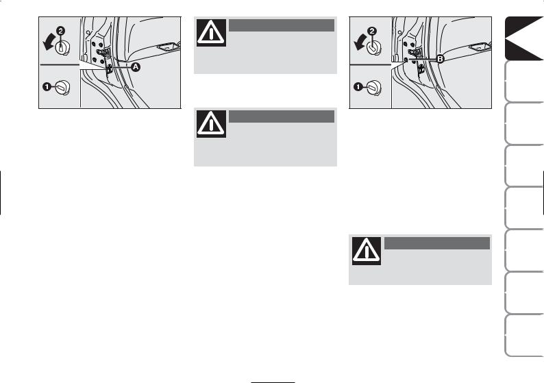
EMERGENCY DOOR UNLOCKING DEVICE fig. 18
The doors are provided with a device for locking all the door using the lock in case of a power fault.
Proceed as follows to lock the doors:
insert the ignition key in lock B
turn the device to position 1 and close the door.
fig. 18 |
L0D0247 |
|
To reopen the doors:
insert the key in the lock on driver’s side and turn it anticlockwise
open the driver’s door
operate the door levers from the inside of the vehicle for the remaining doors.
WARNING
Do not operate the child lock and the door handle
at the same time.
DASHBOARD |
AND |
CONTROLS |
SAFETY |
|
|
STARTING |
AND DRIVING |
|
WARNING |
LIGHTS AND |
MESSAGES |
IN AN |
EMERGENCY |
|
MAINTENANCE |
AND CARE |
|
TECHNICAL |
SPECIFICA- |
TIONS |
INDEX |
|
|
19
DASHBOARD |
AND |
CONTROLS |
|
|
SAFETY |
|
STARTING |
AND DRIVING |
WARNING |
LIGHTS AND |
MESSAGES |
|
IN AN |
EMERGENCY |
|
MAINTENANCE |
AND CARE |
TECHNICAL |
SPECIFICA- |
TIONS |
|
|
INDEX |
20
IGNITION SWITCH
The key can be turned to 3 different positions:
STOP: engine off, key extractable, steering locked. Some electric devices (e.g. sound system, central door locking system, etc.) may work.
MAR: driving position. All electric devices may work.
AVV: engine starting (unstable position).
The ignition switch is fitted with a safety system that, in the event the engine is not started, turns back the ignition key to STOP before repeating the starting operation.
fig. 19 |
L0D0021m |
|
WARNING
Under no circumstances should aftermarket operations involving steering system or
steering column modifications (e.g.: installation of alarm) be carried out that could badly affect performance and safety. This also causes the warranty to become null and void and results in vehicle noncompliance with type-approval requirements.
WARNING
If the ignition device is tampered with (e.g.: attempted theft), have it checked over by a Lancia Dealership as soon as
possible.
WARNING
Always remove the key when you leave your car to prevent someone from accidentally operating the controls. Remember to apply the handbrake. Engage first gear if the car is parked uphill or reverse if the car is parked downhill. Never leave children un-
attended in the car.
STEERING LOCK
Engagement
When the key is in position STOP, remove the key and turn the steering wheel until it is locked.
Switching off
Rock the steering wheel slightly as you turn the ignition key to MAR.
WARNING
Never extract the key while the vehicle is moving. The steering wheel would be locked as soon as the steering wheel is turned. This also applies to when the car is
towed.

INSTRUMENTS
SPEEDOMETER Fig. 20
This indicates the vehicle speed.
REV COUNTER Fig. 21
This indicates the engine revolution per minute.
IMPORTANT The electronic injection control system gradually shuts off the flow of fuel when the engine is ‘overrevving’ resulting in a gradual loss of engine power.
When the engine is idling, the rev counter may indicate a gradual or sudden increase of the speed.
This is normal and does not indicate a fault. It may be caused, for example, by the operation of the climate control system or fan. In these case, a slow change in engine speed is used to protect the battery charge.
fig. 20 |
L0D0241m |
fig. 22 |
L0D0023m |
|
|
fig. 21 |
L0D0242m |
|
FUEL LEVEL GAUGE Fig. 22
The instrument shows the litres of fuel contained in the tank (see the “Refuelling” paragraph for a description).
fig. 23 |
L0D0024m |
|
The reserve warning light A turns on to indicate that approximately 6 litres of fuel are left in the tank.
Do not travel with the tank nearly empty: lack of fuel supply could damage the catalyser.
DASHBOARD |
AND |
CONTROLS |
SAFETY |
|
|
STARTING |
AND DRIVING |
|
WARNING |
LIGHTS AND |
MESSAGES |
IN AN |
EMERGENCY |
|
MAINTENANCE |
AND CARE |
|
TECHNICAL |
SPECIFICA- |
TIONS |
INDEX |
|
|
21

DASHBOARD |
AND |
CONTROLS |
|
|
SAFETY |
|
STARTING |
AND DRIVING |
WARNING |
LIGHTS AND |
MESSAGES |
|
IN AN |
EMERGENCY |
|
MAINTENANCE |
AND CARE |
TECHNICAL |
SPECIFICA- |
TIONS |
|
|
INDEX |
ENGINE
COOLANT TEMPERATURE GAUGE fig. 23
Warning light A indicates overheating of the engine coolant. In this case, stop the engine and contact a Lancia Dealership. This shows the temperature of the engine coolant fluid and starts working when the fluid temperature exceeds approx. 50°C. In normal conditions, the needle may point to different positions according to use and the engine cooling system management.
IMPORTANT The needle will point to the lowest value of the scale (low temperature) and warning light A will light up to indicate a fault in the system. Go to a Lancia Dealership to have the system checked.
MULTIFUNCTIONAL DISPLAY
(on two-line modal panel)
The car can be equipped with the multifunction display for showing useful information necessary when driving according to settings.
If the needle reaches the red area, stop the engine immediately and contact a Lancia Dealership.
fig. 24 |
L0D0497m |
|
“STANDARD” SCREEN fig. 24
The standard screen shows the following information:
AOdometer (kilometres or miles travelled)
B Clock (always displayed, even with key extracted and front doors closed)
CHeadlight adjustment (only with dipped beam headlights on)
D Gear shift suggestion.
NOTE When opening one of the front doors, the display will turn on and show for a few seconds the clock and the kilometres or miles covered.
22

fig. 25 |
L0D0384m |
|
CONTROL BUTTONS fig. 25
+To scroll the menu and the next options or to increase the displayed value.
MODE Press briefly to access the menu and/or go to next screen or to confirm the required menu option.
Hold pressed to go back to the standard screen.
–To scroll the menu and the previous options or to decrease the displayed value.
NOTE Buttons + and – activate different functions according to the following situations.
SET-UP MENU
The “Set-up Menu” is used for the following adjustments and/or settings:
SETTING THE CLOCK
SETTING THE BUZZER VOLUME
SETTING THE SPEED LIMIT
SETTING THE UNIT OF MEASUREMENT.
Setting the clock
The clock is set to 24 hours when the car is delivered.
Proceed as follows to set the required time:
repeatedly press MODE to display “Hour”;
press + to increase one minute;
press – to decrease one minute;
Hold buttons + or – pressed for a few seconds to run the clock forwards or backwards rapidly until the buttons are released.
Hold button MODE pressed for longer than two seconds to confirm the change made to the time.
Setting the buzzer volume
To set the desired volume, proceed as follows:
repeatedly press MODE to display “bUZZ”;
press + to increase the volume;
press – to decrease the volume;
Hold button MODE pressed for longer than two seconds to confirm the change made.
Setting the speed limit
A speed limit can be set and the system will inform the drive when the limit is exceeded by means of an indication on the display and the buzzer. Proceed as follows to set:
This function is “OFF” when the car is delivered.
DASHBOARD |
AND |
CONTROLS |
SAFETY |
|
|
STARTING |
AND DRIVING |
|
WARNING |
LIGHTS AND |
MESSAGES |
IN AN |
EMERGENCY |
|
MAINTENANCE |
AND CARE |
|
TECHNICAL |
SPECIFICA- |
TIONS |
INDEX |
|
|
23

DASHBOARD |
AND |
CONTROLS |
|
|
SAFETY |
|
STARTING |
AND DRIVING |
WARNING |
LIGHTS AND |
MESSAGES |
|
IN AN |
EMERGENCY |
|
MAINTENANCE |
AND CARE |
TECHNICAL |
SPECIFICA- |
TIONS |
|
|
INDEX |
Proceed as follows to select:
repeatedly press MODE until “SPEEd” appears;
press + to increase the value corresponding to speed (the maximum limit is 250 km/h);
press – to decrease the value corresponding to speed (the limit is 30 km/h under which it switches to “OFF”);
to confirm the setting, hold button MODE pressed for longer than two seconds.
Setting the unit of measurement
Proceed as follows to set the required unit of measurement (kilometres or miles):
repeatedly press MODE to display
Unit”;
press button + or – to change the unit of measurement;
to confirm the setting, hold button MODE pressed for longer than two seconds.
Fuel inertia
switch tripped indication
The indication appears automatically if the fuel inertia switch trips follow a collision of considerable severity.
The switch cuts off fuel feed.
See the “Fuel inertia switch” chapter for more information.
WARNING
If after the “FPSon” message appears, you smell fuel or see leaks from the fuel sys-
tem, do not reset the switch to avoid fine risk.
24

MULTIFUNCTIONAL DISPLAY
(on three-line comfort panel)
The car can be equipped with the multifunction display for showing useful information necessary when driving according to settings.
“STANDARD” SCREEN fig. 26
The standard screen shows the following information:
ADate / Odometer (covered km or miles).
B Clock (always displayed, even with ignition key removed and front doors closed).
C External temperature.
fig. 26 |
L0D0496m |
|
DHeadlight adjustment (only with dipped beam headlights on).
E Gear shift suggestion.
NOTE When opening one of the front doors, the display will turn on and show for a few seconds the clock and the kilometres or miles covered.
fig. 27 |
L0C0384m |
|
CONTROL BUTTONS fig. 27
+To scroll the menu and the next options or to increase the displayed value.
MODE Press briefly to access the menu and/or go to next screen or to confirm the required menu option.
Hold pressed to go back to the standard screen.
–To scroll the menu and the previous options or to decrease the displayed value.
NOTE Buttons + and – activate different functions according to the following situations.
DASHBOARD |
AND |
CONTROLS |
SAFETY |
|
|
STARTING |
AND DRIVING |
|
WARNING |
LIGHTS AND |
MESSAGES |
IN AN |
EMERGENCY |
|
MAINTENANCE |
AND CARE |
|
TECHNICAL |
SPECIFICA- |
TIONS |
INDEX |
|
|
25

DASHBOARD |
AND |
CONTROLS |
|
|
SAFETY |
|
STARTING |
AND DRIVING |
WARNING |
LIGHTS AND |
MESSAGES |
|
IN AN |
EMERGENCY |
|
MAINTENANCE |
AND CARE |
TECHNICAL |
SPECIFICA- |
TIONS |
|
|
INDEX |
Headlight adjustment (only
with dipped beam headlights on).
– when the standard page is displayed, this is used to adjust the headlights (see the “Headlights” paragraph in this chapter).
Set-up menu
– for scrolling the menu up and down;
–to increase or decrease values during settings.
SET-UP MENU Fig. 28
The menu comprises a series of functions arranged in a “circular fashion” which can be selected through buttons + and – to access the different select operations and settings (setup) given in the following paragraphs.
The setup menu is activated by pressing briefly button MODE.
Single presses on buttons + and – will scroll the setup menu options.
Handling modes are different according to the characteristic of the option selected.
NOTE Only the following functions can be adjusted/set on the Instrument Panel display if the Connect Nav+ system is present: “Lights”, “Speed limit”, “Light sensor” (for versions/ markets, where provided), “Belt buzzer” and “Passenger airbag”. The other functions are shown on the Connect Nav+ system display. Set and adjustment them there.
Selecting a menu option
–briefly press button MODE to select the menu option that needs to be changed.
–press buttons + and – (by single presses) to select the new setting;
–briefly press button MODE to store the new setting and at the same time go back to the previously selected menu option.
Selecting “Date” and “Clock”:
–briefly press button MODE to select the first value to be changed (e.g. hours /minutes or year / month / day).
–press buttons + and – (by single presses) to select the new setting;
–briefly press button MODE to store the new setting and go to the next setup menu option: if this is the last one you will go back to the previously selected option of the main menu.
Hold the
button MODE pressed to:
– quit set-up and to save only the changes stored by the user (and confirmed by pressing button MODE).
The setup menu environment is timed. Only the changes saved by the user by briefly pressing MODE).ill be saved when the menu is automatically closed.
26

Example:
Deutsch
Italiano |
English |
|
|
Português |
Español |
|
|
|
Français |
On the standard screen, briefly press MODE to start browsing. Press + or – browse within the menu. NOTE Only the short menu may be accessed for reasons of safety while the car is moving (“Brightness” and “Speed Limit”). Stop the car to access the full menu. On car equipped with Connect Nav+, many functions are displayed on the navigator readout.
Example:
Day
Year Month
|
|
|
|
|
+ |
+ |
|
|
MODE |
|
|
|
|
|
|
|
button |
||
|
|
|
|
+ |
– |
– |
|
|
pressed |
|
|
|
|
+ |
|
briefly |
|||
MODE |
|
|
|
– |
TRIP B |
|
|
|
|
|
|
|
LIGHT SENSOR |
SET CLOCK |
– |
|
|
||
button |
|
|
+ |
|
|
||||
pressed |
|
|
|
|
|
|
|
|
|
briefly |
|
|
– |
SPEED LIMIT |
|
CLOCK MODE |
– |
+ |
|
|
|
|
|
|
|
||||
|
+ |
– |
QUIT MENU |
|
|
SET DATE |
|
– |
|
|
|
|
|
|
|||||
|
|
|
|
|
|
|
|
||
|
|
|
|
|
|
|
|
|
+ |
PASSENGER AIRBAG
+ |
– |
|
|
|
SERVICE |
+ |
– |
|
BELT BUZZER
(*) (for versions/markets, where provided)
 – BUTTON VOLUME
KEY
–
+
UNIT DIST. |
|
|
– |
CONSUMPTION |
+ |
|
|
– |
|
TEMP. UNIT |
|
+ |
BUZZER VOLUME |
LANGUAGE |
|
|
– |
– |
|
|
+ |
||
|
+ |
||
fig. 28 |
+ |
||
|
– |
+ |
|
(*) This function may only be displayed after the SBR system is deactivated by a Lancia Dealership.
SAFETY |
|
|
STARTING |
AND DRIVING |
|
WARNING |
LIGHTS AND |
MESSAGES |
IN AN |
EMERGENCY |
|
MAINTENANCE |
AND CARE |
|
TECHNICAL |
SPECIFICA- |
TIONS |
INDEX |
|
|
27

DASHBOARD |
AND |
CONTROLS |
|
|
SAFETY |
|
STARTING |
AND DRIVING |
WARNING |
LIGHTS AND |
MESSAGES |
|
IN AN |
EMERGENCY |
|
MAINTENANCE |
AND CARE |
TECHNICAL |
SPECIFICA- |
TIONS |
|
|
INDEX |
Speed limit
This function is used to set the car speed limit (km/h or mph); the driver is immediately alerted when this limit is exceeded (see section “Warning lights and messages”).
To set the desired speed limit, proceed as follows:
–briefly press MODE, the message (speed limit) will appear on the display.
–press button + or – to select speed limit activation (On) or deactivation
(Off);
– if the function has been activated (On), press buttons + or – to select the required speed limit and then press MODE to confirm.
NOTE The speed may be set in the range from 30 to 250 km/h, or from 20 to 155 mph according to the previously chosen unit (see “Setting the distance unit”) described below. The setting will increase/decrease by five units each time button + / – is pressed. Hold button + / – pressed to increase/decrease the setting rapidly. Complete the setting by briefly pressing the button when you approach the required setting.
– briefly press button MODE to go back to the menu screen or hold the button pressed to go back to the standard screen without storing the settings.
To cancel the setting, proceed as follows:
–briefly press button MODE: (On) will flash on the display;
–press button +: (Off) will flash on the display;
–briefly press button MODE to go back to the menu screen or hold the button pressed to go back to the standard screen without storing the settings.
28

Adjusting the automatic headlight sensor sensitivity (light sensor)
(for versions/markets, where provided)
This function is used to adjust the dusk sensor sensitivity to three levels (level 1 = minimum, level 2 = medium, level 3 = maximum); higher the sensitivity, lower the quantity of external light needed to switch the headlights on. The device is set to level “2” when the car is delivered.
Proceed as follows to set:
–briefly press button MODE, the previously set level will flash on the display;
–press button + or – for setting;
–briefly press button MODE to go back to the menu screen or hold the button pressed to go back to the standard screen without storing the settings.
Turning Trip B on/off (Trip B)
This function may be used to activate (On) or deactivate (Off) the Trip B (partial trip).
For further information see “Trip computer”.
Proceed as follows to turn on and off:
–briefly pressMODE ON or OFF flashes on the display (according to the previous setting);
–press button + or – for setting;
–briefly press button MODE to go back to the menu screen or hold the button pressed to go back to the standard screen without storing the settings.
Setting the clock (Set clock)
This function is used to set the clock.
To carry out the adjustment, proceed as follows:
–briefly press button MODE: the “hours” will flash on the display;
–press button + or – to set;
–briefly press button MODE: “minutes” will start flashing on the display;
–press button + or – to set;
NOTE The setting will increase or decrease by one unit each time + or – is pressed. Hold the button pressed to increase/decrease the setting rapidly. Complete the setting by briefly pressing the button when you approach the required setting.
– briefly press button MODE to go back to the menu screen or hold the button pressed to go back to the standard screen without storing the settings.
DASHBOARD |
AND |
CONTROLS |
SAFETY |
|
|
STARTING |
AND DRIVING |
|
WARNING |
LIGHTS AND |
MESSAGES |
IN AN |
EMERGENCY |
|
MAINTENANCE |
AND CARE |
|
TECHNICAL |
SPECIFICA- |
TIONS |
INDEX |
|
|
29
 Loading...