


Dear Customer,
We would like to congratulate and thank you for selecting LANCIA.
We have written this handbook to help you get familiar with all the features of your car.
You should read it right through before taking the road for the first time.
You will find information, tips and important warnings regarding the driving of your car to help you derive the best performance from the technological features of your LANCIA. The booklet also provides a description of special features and tips as well as essential information for correct care, maintenance, safety of car driving and use and preservation of your LANCIA over time.
You are recommended to carefully read the warnings and indications, marked with the respective symbols, at the end of the page:
personal safety;
the car integrity;
environmental protection.
The enclosed Warranty Booklet lists the services that LANCIA offers to its Customers:
-the Warranty Certificate with terms and conditions for maintaining its validity;
-the range of additional services available to LANCIA Customers.
We are confident that these instructions will help you become familiar with the car and appreciate your new car and LANCIA after-sales staff who will be at your service.
Best regards and happy motoring!
This Owner Handbook describes all LANCIA Musa versions. As a consequence, you should only consider the information which is related to the engine and bodywork version of the car you have purchased.

SAFETY AND ENVIRONMENTAL PROTECTION
Safety and environmental protection are the guidelines that have inspired the LANCIA Musa project from its very beginning.
This approach has enabled LANCIA Musa to successfully pass the extremely strict safety tests to which it was subjected.
For this reason, the car has reached the maximum levels in its category and has probably been a precursor of future parameters.
The continuous search for new and efficient solutions in terms of environmental protection makes LANCIA Musa a model to be followed suit.
All the versions are equipped with environmental protection devices which reduce hazardous emissions of exhaust gases at levels that go beyond the limits established by the existing regulations.
ENVIRONMENTAL PROTECTION
LANCIA Musa has been designed and manufactured having the traditional aspects of performances and safety as the major targets, but also keeping in mind the increasingly pressing issues relating to environmental protection and safeguard.
The selected materials, techniques and special devices installed are the result of a process that enables dramatic reduction of hazardous environmental impact, at the same time ensuring compliance with the strictest international standards.

USE OF ENVIRONMENT-FRIENDLY MATERIALS
None of the components installed on LANCIA Musa contains asbestos. The padding and air conditioning system are CFC-free (Chlorofluorocarbons), these gases being reliable for the depletion of the ozone layer. Dying agents and anticorrosion coating of the bolts and screws no longer contain cadmium, which pollutes the air and waterbeds.
EMISSION-REDUCING DEVICES (petrol engines)
Three-way catalytic converter (catalytic converter)
The exhaust system features a catalyst made with alloys of noble metals. It is installed in a stainless steel housing which is resistant to high operating temperatures.
The catalyst converts the unburnt hydrocarbons, carbon oxide and nitrogen oxides that are present in the exhaust gases (although in small quantities thanks to electronic injection ignition systems) into non-polluting compounds.
As the catalytic converter reaches high temperatures during car operation, we recommend that the car should not be parked on materials that may pose a risk of flammability (e.g. paper, fuel oils, dry grass or leaves, etc.).
Lambda sensors
These sensors (Lambda) detect the oxygen content in the exhaust gases. Lambda sensors produce a signal which is used by the electronic control unit of the injection and ignition system for regulating the air-fuel mix.
Fuel evaporation system
Even when the engine is not running, it is not possible to prevent the formation of petrol vapours. For this reason, a system has been developed to “catch” these vapours in a special activated carbon vessel.
While the engine is running, these vapours are aspirated and delivered to combustion.

EMISSION-REDUCING DEVICES (Multijet engines)
Oxidising catalytic converter
It is used to convert the polluting substances in the exhaust gases (carbon oxide, unburnt hydrocarbons and particulate) into harmless substances by reducing the smoke opacity index and the typical smell of exhaust gases produced by diesel engines.
The catalyst converter comprises a stainless steel metal enclosure which contains a ceramic honey-comb body on which the noble metal, having a catalyst function, is installed.
Exhaust gas recirculation system (E.G.R.)
It is used to recirculate, i.e. recycle, a portion of the exhaust gases in percentage terms that change according to the engine operating conditions.
When necessary, it is used to check the emissions of nitrogen oxides.

MUST BE READ!
REFUELLING
Petrol engines: exclusively refuel the car with unleaded petrol having a RON that must not be below 95.
KMultijet engines: exclusively refuel the car with vehicle propulsion diesel fuel conforming to the European specification EN590.
The use of other products or mixtures may damage the engine beyond repair and consequently cause the warranty to be void depending on the damage caused.
ENGINE STARTING
Petrol engines: make sure that the handbrake is engaged; set the gearshift lever to neutral; fully depress the clutch without pressing the accelerator, then turn the ignition key to AVV and release it as soon as the engine has started.
Multijet engines: turn the ignition key to MAR and wait until the warning lights Y and m go off. Then , turn the ignition key to AVV and release it as soon as the engine has started.
PARKING ON FLAMMABLE MATERIAL
The catalytic converter develops high temperature during operation. Do not park on grass, dry leaves,pine needles or other flammable material: fire risk.
ENVIRONMENTAL PROTECTION
The car is fitted with a system that allows continuous diagnosis of the emission-related components to ensure better respect of the environment.

ELECTRICAL ACCESSORIES |
|
|
If, after buying the car, you decide to add accessories that require electrical |
power supply |
|
(that will gradually drain the battery), address the Lancia Dealership. They can calculate the overall |
||
electrical absorption and check that the car electric system can support the required load. |
|
|
CODE card
Keep it in a safe place, not in the car. We recommend that you should always carry the electronic code provided on the CODE card with you, in case you need to perform an emergency start.
SCHEDULED SERVICING
Correct car maintenance is essential for ensuring that the car stays in tip-top condition and safeguards its safety features, its environmental friendliness and low running costs for a long time to come.
THE OWNER’S MANUAL CONTAINS…
... important information, advise and warnings for correct use, driving safety and maintenance of your car over time. Special attention must be paid to the symbols provided " (safety of persons) # (environmental protection) â (car integrity).
If the multifunction display shows a message reading “See handbook”, you should refer to the section “Warning lights and messages” in this handbook.

DASHBOARD AND CONTROLS
DASHBOARD ........................................................ |
8 |
INSTRUMENT PANEL.......................................... |
10 |
SYMBOLS ............................................................. |
11 |
THE LANCIA CODE SYSTEM.............................. |
11 |
THE KEY AND DOOR LOCKING KIT ................. |
13 |
IGNITION DEVICE .............................................. |
20 |
INSTRUMENTS ................................................... |
21 |
MULTIFUNCTIONAL DISPLAY |
|
(on two-line modal panel)...................................... |
22 |
MULTIFUNCTIONAL DISPLAY |
|
(on three-line modal panel).................................... |
25 |
ADJUSTING THE SEATS ..................................... |
38 |
HEAD RESTRAINTS ............................................ |
44 |
ADJUSTING THE STEERING WHEEL ............... |
45 |
REARVIEW MIRRORS .......................................... |
46 |
HEATING/CLIMATE CONTROL SYSTEM .......... |
47 |
MANUAL CLIMATE CONTROL SYSTEM ........... |
48 |
AUTOMATIC CLIMATE CONTROL |
|
SYSTEM (TWO-ZONE) ....................................... |
52 |
EXTERNAL LIGHTS ........................................... |
62 |
WINDOW WASHING ............................................ |
64 |
CRUISE CONTROL ............................................. |
67 |
CEILING LIGHTS................................................. |
69 |
LIGHT CONTROL BUTTONS .............................. |
71 |
FUEL CUT-OFF INERTIAL SWITCH................... |
72 |
INTERNAL EQUIPMENT .................................... |
73 |
SMOKERS KIT...................................................... |
75 |
SUN VISORS ......................................................... |
76 |
SUNROOF ............................................................ |
76 |
POWER WINDOWS ............................................. |
78 |
BOOT .................................................................... |
80 |
BONNET ............................................................... |
82 |
ROOF BARS .......................................................... |
83 |
HEADLIGHTS ...................................................... |
84 |
ABS SYSTEM ....................................................... |
85 |
EOBD SYSTEM .................................................... |
86 |
SOUND SYSTEM .................................................. |
87 |
ACCESSORIES PURCHASED BY THE OWNER .. |
88 |
“DUALDRIVE” ELECTRIC POWER |
|
STEERING SYSTEM ............................................ |
89 |
PARKING SENSORS ............................................ |
90 |
REFUELLING ...................................................... |
92 |
ENVIRONMENTAL PROTECTION ..................... |
94 |
DASHBOARD |
AND CONTROLS |
|
SAFETY |
DEVICES |
|
STARTING |
AND |
DRIVING |
WARNING |
LIGHTS AND |
MESSAGES |
IN AN |
EMERGENCY |
|
MAINTENANCE |
AND CARE |
|
TECHNICAL |
SPECIFICATIONS |
|
INDEX |
|
|
7
|
DASHBOARD |
AND CONTROLS |
|
SAFETY |
DEVICES |
STARTING |
AND |
DRIVING |
WARNING |
LIGHTS AND |
MESSAGES |
|
IN AN |
EMERGENCY |
|
MAINTENANCE |
AND CARE |
|
TECHNICAL |
SPECIFICATIONS |
|
|
INDEX |
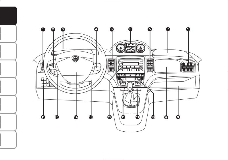
DASHBOARD
The presence and position of the controls, instruments and indicators may vary according to the different versions.
The upper and lower central panel offers several solutions according to the Customer’s requirements (see the illustrations below).
fig. 1
L0D0374m
1. Side air vents - 2. Left stalk - 3. Upper left-hand glove box - 4. Right stalk - 5. Central air vents - 6. Instrument panel - 7. Upper right-hand glove box - 8. Glove box compartment - 9. Passenger’s airbag - 10. Controls for heating/ventilation/ climate control - 11. Control buttons - 12. Sound system (where provided) - 13. Ignition converter - 14. Driver’s airbag -
15. Cruise control (where provided).
8

fig. 2 |
L0D0231m |
|
fig. 3 |
L0D0232m |
|
fig. 4 |
L0D0359m |
|
Upper central panel:
with fixed glove box compartment, A-fig. 2, and extractable compartment (DIN), B-fig. 2, for audio system installation;
with required auto system, fig. 3;
with Connet Nav+, fig. 4;
Lower central panel:
fig. |
5 |
L0D0234m |
|
||
fig. |
6 |
L0D0235m |
|
with manual climate control system,
B-fig. 5;
with automatic two-zone climate control system, C-fig. 6.
DASHBOARD |
AND CONTROLS |
|
SAFETY |
DEVICES |
|
STARTING |
AND |
DRIVING |
WARNING |
LIGHTS AND |
MESSAGES |
IN AN |
EMERGENCY |
|
MAINTENANCE |
AND CARE |
|
TECHNICAL |
SPECIFICATIONS |
|
INDEX |
|
|
9
|
DASHBOARD |
AND CONTROLS |
|
SAFETY |
DEVICES |
STARTING |
AND |
DRIVING |
WARNING |
LIGHTS AND |
MESSAGES |
|
IN AN |
EMERGENCY |
|
MAINTENANCE |
AND CARE |
|
TECHNICAL |
SPECIFICATIONS |
|
|
INDEX |
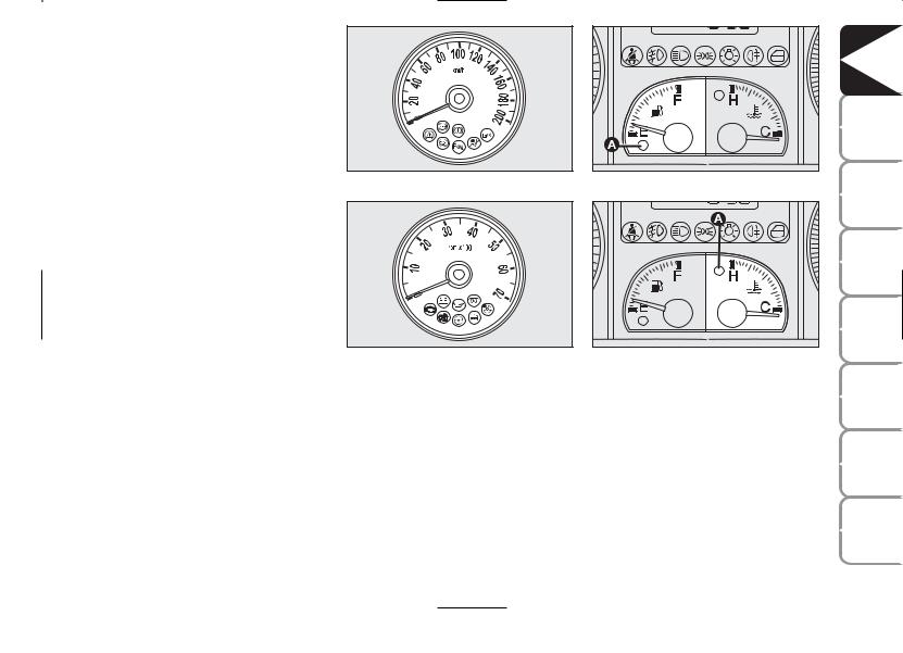
INSTRUMENT PANEL |
|
|
Modal panel |
|
|
A - Speedometer (speed indicator) |
|
|
B – Fuel level gauge with reserve warning light |
|
|
C – Engine coolant temperature gauge and |
|
|
excessive temperature warning light |
|
|
D - Rev. counter |
|
|
E - Multifunctional display |
|
|
c m Warning lights installed on Multijet versions |
fig. 7 |
|
only |
||
|
Comfort
A - Speedometer (speed indicator)
B – Fuel level gauge with reserve warning light
C – Engine coolant temperature gauge and excessive temperature warning light
D - Rev. counter
E - Reconfigurable multifunctional display
c m Warning lights installed on Multijet versions only
fig. 8
L0D0372m
L0D0010m
10
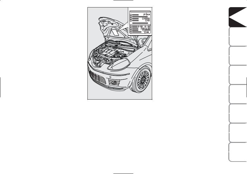
SYMBOLS
Special coloured labels have been attached near or actually on some of the components of your car. These labels bear symbols that draw your warning to the precautions required when handling the component in question.
The plate summarising the symbols used can be found under the bonnet, fig. 9.
fig. 9 |
L0D0375m |
|
THE LANCIA CODE SYSTEM
This is an electrical engine locking system which increases protection against attempted theft of the car. It is automatically activated when the ignition key is extracted.
Each key contains an electronic device which modulates the signal emitted during ignition by an antenna built in the ignition device. This signal is the ‘password’, which changes at each ignition and is used by the control unit to acknowledge the key and allow ignition.
DASHBOARD |
AND CONTROLS |
|
SAFETY |
DEVICES |
|
STARTING |
AND |
DRIVING |
WARNING |
LIGHTS AND |
MESSAGES |
IN AN |
EMERGENCY |
|
MAINTENANCE |
AND CARE |
|
TECHNICAL |
SPECIFICATIONS |
|
INDEX |
|
|
11
|
DASHBOARD |
AND CONTROLS |
|
SAFETY |
DEVICES |
STARTING |
AND |
DRIVING |
WARNING |
LIGHTS AND |
MESSAGES |
|
IN AN |
EMERGENCY |
|
MAINTENANCE |
AND CARE |
|
TECHNICAL |
SPECIFICATIONS |
|
|
INDEX |
OPERATION
Each time the car is started by turning the ignition key to MAR, the Lancia CODE system control unit sends an acknowledgement code to the engine control unit to deactivate the inhibitor. The code is sent only if the control unit of the Lancia CODE system has acknowledged the code received from the key. Each time the ignition key is turned to STOP, the Lancia CODE system deactivates the functions of the electronic engine control unit.
If, during ignition, the code is not correctly recognized, a warning light Yis lit on the instrument panel.
In this case, turn the key to STOP and then back to MAR. Try with the other keys provided if the problem persists. If the engine will not start up after this operation contact the Lancia Dealership.
IMPORTANT Each key has its own code which must be stored by the system ECU. Contact the Lancia Dealership to have new keys (up to max. eight) with the code stored in them.
Warningdriving light Ycoming on when
If the warning light Yturns on, the system is running a self-test (such as following a voltage failure). If the problem persists, contact the Lancia Dealership.
The electronic components inside the key may be damaged if the key is submitted to sharp knocks.
12
THE KEY AND DOOR LOCKING KIT
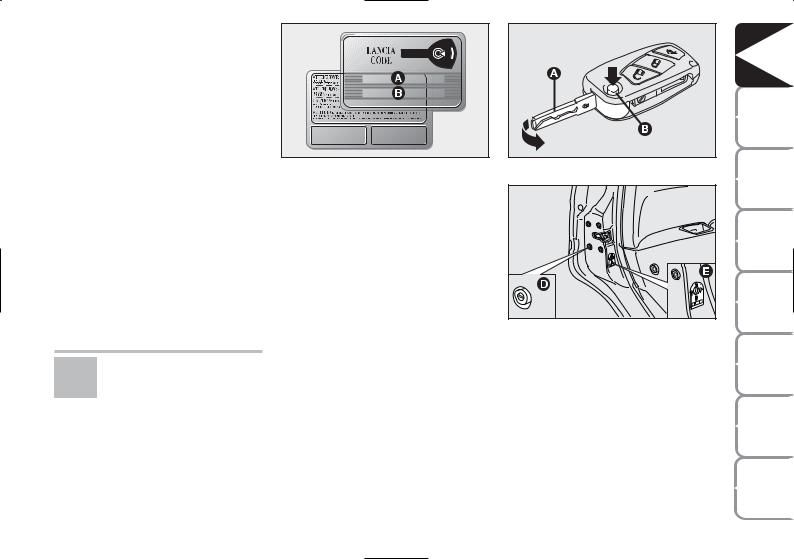
CODE CARD Fig. 10 (Optional for versions/markets where applicable)
The car is delivered with the ignition key and the CODE card which bears the following data:
the mechanical key code B to be given to the Lancia Dealership when ordering duplicate keys.
IMPORTANT In order to ensure perfect efficiency of the electronic devices inside the keys, they should never be exposed to direct sunlight.
All the keys and the CODE card must be handed over to the new owner when selling the car.
fig. 10 |
L0D0376m |
|
MAIN KEY WITH REMOTE CONTROL fig. 11
The metal insert of the key A is recessed in the grip.
The key operates:
the ignition switch;
the lock of the door on the driver’s side;
the lock/release device of the fuel flap (on versions equipped with a lockable fuel plug)
fig. 11 |
L0D0377m |
|
|
fig. 12 |
L0D0246m |
|
engagement of the device, D-fig. 12, for locking external opening of the front and rear doors when the electric system does not work (e.g. the battery is down);
engagement of the child safety lock device, E-fig. 12, installed on the rear doors.
Button B-fig. 11 enables opening of the metal insert A.
DASHBOARD |
AND CONTROLS |
|
SAFETY |
DEVICES |
|
STARTING |
AND |
DRIVING |
WARNING |
LIGHTS AND |
MESSAGES |
IN AN |
EMERGENCY |
|
MAINTENANCE |
AND CARE |
|
TECHNICAL |
SPECIFICATIONS |
|
INDEX |
|
|
13

|
DASHBOARD |
AND CONTROLS |
|
SAFETY |
DEVICES |
STARTING |
AND |
DRIVING |
WARNING |
LIGHTS AND |
MESSAGES |
|
IN AN |
EMERGENCY |
|
MAINTENANCE |
AND CARE |
|
TECHNICAL |
SPECIFICATIONS |
|
|
INDEX |
To refit metal insert A, proceed as follows:
Press button B and hold it pressed.
move the metal insert A.
Release button B and turn the metal insert A until hearing the click that indicates correct locking.
The button Ëactivates the release device for doors, tailgate and fuel flap (where provided).
The button Áactivates the release device for doors, tailgate and fuel flap (where provided).
The button R activates opening of the tailgate.
WARNING
Press button B-fig. 11 only after moving the key away from your body, especially your
eyes, and from objects which could get damaged (e.g. your clothes). Do not leave the key unattended, because someone, a child especially, may accidentally press the button while handling the key.
Door and tailgate lock release
Short pressure on button Ë: lock release of doors, tailgate and fuel flap, timed switching on of the internal ceiling lights and double flashing of direction indicators.
Door locks are automatically released in case of intervention of the inertial fuel cut-off switch.
Use the “Setup Menu” of the multifunctional reconfigurable display (see the dedicated paragraph in section “Dashboard and Controls”) to set the system in such a way that only the door on the driver’s side is released when pressing button Ë.
fig. 13 |
L0D0378m |
|
IMPORTANT The remote control frequency may be disturbed by radio transmissions outside the car (e.g. cellular phones, radio amateurs, etc.). If this is the case, the remote control may operate incorrectly.
Door and tailgate locking
Short pressure on button Á: remote lock of doors, tailgate and fuel flap, switching off of the internal ceiling lights and single flashing of direction indicators.
14
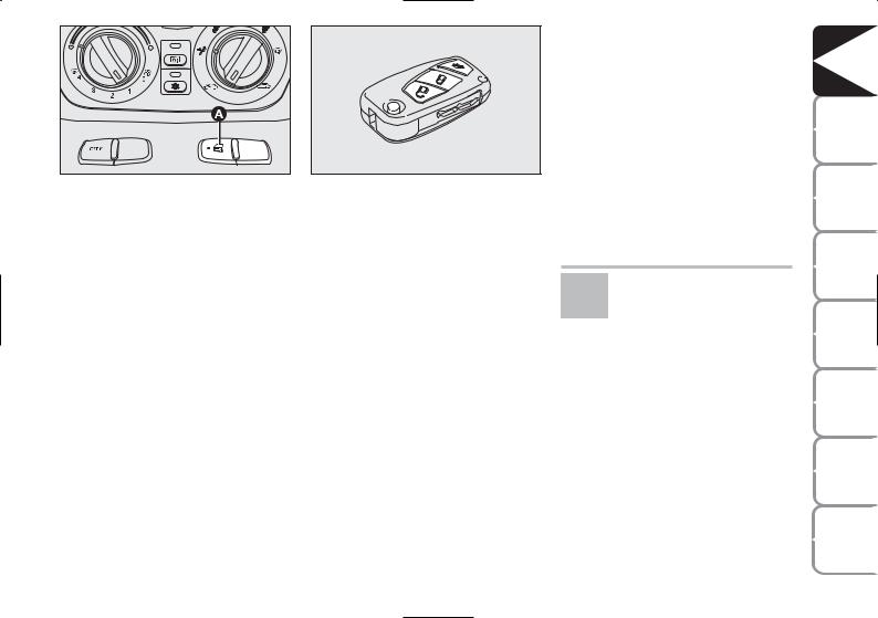
fig. 14 |
L0D0417m |
|
Deterrence led indications
When locking the doors, the deterrence LED A-fig. 14 on the button switches on for about 3 seconds. Then, it starts flashing (deterrence function). If one or more than one door or the tailgate does not close correctly when locking it, the LED and direction indicators start flashing quickly.
IMPORTANT The remote control frequency may be disturbed by radio transmissions outside the car (e.g. cellular phones, radio amateurs, etc.). If this is the case, the remote control may operate incorrectly.
fig. 15 |
L0D0378m |
|
Remote tailgate opening fig. 15
Press the button R , and hold it pressed, to release (open) the tailgate remotely. Tailgate opening is indicated by double flashing of the direction indicators; tailgate closing by single flashing.
IMPORTANT The remote control frequency may be disturbed by radio transmissions outside the car (e.g. cellular phones, radio amateurs, etc.). If this is the case, the remote control may operate incorrectly.
Door locking from the inside
Keep the doors locked and press the button A-fig. 14 positioned at the centre of the dashboard to either lock or release the doors.
IMPORTANT If one door is not correctly locked, or a system fault occurs, doors cannot be locked from the inside.
After eliminating the cause of the problem, the device resumes regular operation.
If the button for locking doors from the inside is accidentally pressed, only the doors opened for getting out
of the car are released; the tailgate remains locked. For system reset press the lock/release buttons again.
DASHBOARD |
AND CONTROLS |
|
SAFETY |
DEVICES |
|
STARTING |
AND |
DRIVING |
WARNING |
LIGHTS AND |
MESSAGES |
IN AN |
EMERGENCY |
|
MAINTENANCE |
AND CARE |
|
TECHNICAL |
SPECIFICATIONS |
|
INDEX |
|
|
15

|
DASHBOARD |
AND CONTROLS |
|
SAFETY |
DEVICES |
STARTING |
AND |
DRIVING |
WARNING |
LIGHTS AND |
MESSAGES |
|
IN AN |
EMERGENCY |
|
MAINTENANCE |
AND CARE |
|
TECHNICAL |
SPECIFICATIONS |
|
|
INDEX |
fig. 16 |
L0D0379m |
|
Replacing the battery of the key with remote control fig. 16
Battery replacement:
press button A and bring the metal insert B to the “open” position;
turn the screw C using a fine bit screwdriver;
take out the battery case D and replace the battery E respecting its polarity;
fit the battery case D back inside the key and lock it turning screw
C.
Request for additional remote controls
The system acknowledges up to 8 remote controls. Should a new remote control be necessary, contact a Lancia Dealership and be ready to present the CODE card, a personal identity document and the car’s ownership documents.
Used batteries are harmful to the environment. They should be disposed of as specified by law in special
containers or taken to a Lancia Dealership, which will take care of their disposal.
16
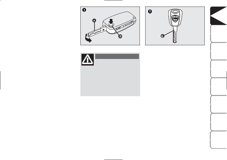
(SPARE) MECHANICAL KEY, fig. 17-18
Depending on the version, the car is either supplied with a recessed key 1 or fixed key 2.
The metal insert A of the key 1 is recessed in the grip.
The button B activates opening of the metal insert A.
The metal insert A is placed back in the grip as follows.
Press button B and hold it pressed.
Move the metal insert A.
Release button B and turn the metal insert A until hearing the click that indicates correct locking.
fig. 17 |
L0D0014m |
|
WARNING
Only press button B with the key away from your body, specifically from your eyes
and from objects which could get damaged (e.g. your clothes). Do not leave the key unattended, because someone, a child especially, may accidentally press the button while handling the key.
fig. 18 |
L0D0380m |
|
The keys are used to activate:
the ignition switch;
the lock of the door on the driver’s side;
the fuel flap lock/release (on versions supplied with a lockable plug)
engagement of the child safety lock device when the electric system does not work (e.g. when the battery is down);
engagement of the child safety lock device on the rear doors.
DASHBOARD |
AND CONTROLS |
|
SAFETY |
DEVICES |
|
STARTING |
AND |
DRIVING |
WARNING |
LIGHTS AND |
MESSAGES |
IN AN |
EMERGENCY |
|
MAINTENANCE |
AND CARE |
|
TECHNICAL |
SPECIFICATIONS |
|
INDEX |
|
|
17
|
DASHBOARD |
AND CONTROLS |
|
SAFETY |
DEVICES |
STARTING |
AND |
DRIVING |
WARNING |
LIGHTS AND |
MESSAGES |
|
IN AN |
EMERGENCY |
|
MAINTENANCE |
AND CARE |
|
TECHNICAL |
SPECIFICATIONS |
|
|
INDEX |
The main functions that can be activated with the keys (with or without remote control) are the following:
Type of key |
Door lock release |
Door locking |
Unlocking the |
|
|
from the outside |
tailgate |
|
|
|
|
Spare |
Turn the key |
Turn the key |
|
mechanical |
anticlockwise |
clockwise |
|
key |
(driver’s side) |
(driver’s side) |
|
|
Turn the key |
Turn the key |
|
|
anticlockwise |
clockwise |
|
Main key |
(driver’s side) |
(driver’s side) |
|
|
|
|
|
with remote control |
|
|
|
|
Short pressing |
Short pressing of |
Prolonged button pressing |
|
of button Ë |
button Á |
(for over 2 seconds) R |
Direction indicators flashing |
blinks twice |
blinks once |
blinks twice |
|
|
|
|
(only when key |
|
|
|
has remote control) |
|
|
|
Deterrence led |
Switching off |
Steady for |
Deterrence led |
|
|
approximately 3 seconds |
|
|
|
and then |
|
|
|
deterrent blinking |
|
Pressing button Ë activates opening of the fuel flap.
18
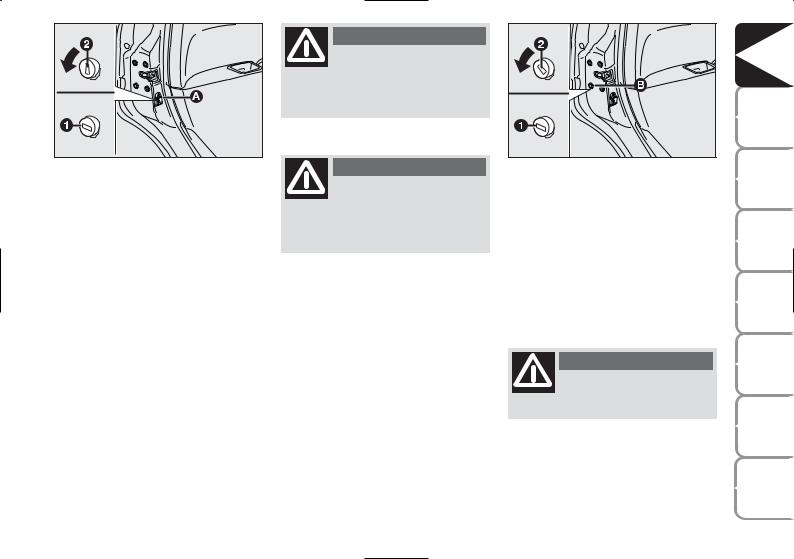
fig. 19 |
L0D0101m |
|
CHILD LOCK SYSTEM fig. 19
This device prevents opening of the rear doors from the inside.
This device can be engaged only with rear doors open.
position 1 - engaged (door locked);
position 2 - disengaged (door can be opened from the inside).
The device A stays on even if the doors are unlocked by the centralised system.
IMPORTANT Always use this device when transporting children.
IMPORTANT After engaging the child lock on both rear doors, check for proper engagement by trying to open a rear door with the internal handle.
WARNING
Engagement of the child lock system A-fig. 19 is ensured exclusively if the revolving
plug is rotated until the correct horizontal position (1) is reached.
WARNING
Disengagement of the child lock system A-fig. 19 is ensured exclusively if the revolving
plug is rotated until the correct vertical position (2) is reached.
EMERGENCY DEVICE FOR EXTERNAL DOOR LOCKING fig. 20
The doors are fitted with an emergency device to lock them when there is no power.
In this case, the car doors are locked as follows.
Fit the ignition key into the revolving plug B.
Turn the device to position 1 and close the door.
fig. 20 |
L0D0247 |
|
The doors are opened as follows.
Fit the key into the revolving plug of the door lock on the driver’s side and turn it anticlockwise.
Open the door on the driver’s side.
Sit in the car and open the remaining doors using the stalks of the opening handles.
WARNING
Do not engage the child lock system simultaneously
with the door opening stalk.
DASHBOARD |
AND CONTROLS |
|
SAFETY |
DEVICES |
|
STARTING |
AND |
DRIVING |
WARNING |
LIGHTS AND |
MESSAGES |
IN AN |
EMERGENCY |
|
MAINTENANCE |
AND CARE |
|
TECHNICAL |
SPECIFICATIONS |
|
INDEX |
|
|
19
|
DASHBOARD |
AND CONTROLS |
|
SAFETY |
DEVICES |
STARTING |
AND |
DRIVING |
WARNING |
LIGHTS AND |
MESSAGES |
|
IN AN |
EMERGENCY |
|
MAINTENANCE |
AND CARE |
|
TECHNICAL |
SPECIFICATIONS |
|
|
INDEX |
20
IGNITION DEVICE
The key can be turned to 3 different positions:
STOP: engine off, key extractable, steering locked. Some electrical devices (e.g. sound system, power windows, etc.) work regularly.
MAR: driving position. All electrical devices work regularly.
AVV: engine starting (unstable position).
The ignition switch is fitted with an electronic safety system that turns the ignition key back to position STOP if the engine will not start, before repeating the starting operation.
fig. 21 |
L0D0021m |
|
WARNING
Under no circumstances should aftermarket works be carried out, because they may
cause tampering with the driving system or steering column (e.g. installation of anti-theft device), which may lead to reduced system performances and loss of the warranty as well as safety-specific problems and non-compliance with the car typeapproval.
WARNING
If the ignition system is tampered with (e.g. after an attempted theft), address a Lancia Dealership to have the system
checked before starting off.
WARNING
Always remove the key from the car when leaving it in order to prevent accidental en-
gagement of the controls. Remember to engage the handbrake. Engage first gear if the car is parked uphill or reverse if the car is parked downhill. Never leave children unattended in the car.
STEERING COLUMN LOCK
Engagement
When the key is in position STOP, remove the key and turn the steering wheel until it is locked.
Disengagement
Rock the steering wheel slightly as you turn the ignition key to MAR.
WARNING
Never extract the key while the car is moving. The steering wheel would be locked as soon as
the steering wheel is turned. This also applies to cases in which the car is towed.
INSTRUMENTS
SPEEDOMETER fig. 22
It shows the car speed.
REV. COUNTER fig. 23
It shows the engine revolutions per minute.
IMPORTANT The electronic injection control system gradually shuts off the flow of fuel when the engine is “overrevving”, thus causing a gradual loss of engine power.
When the engine is idling, the rev counter may indicate a gradual or sudden increase of the speed.
This is normal and does not indicate a fault. It may be caused, for example, by the operation of the climate control system or fan. In these cases, a slow change in engine speed is used to protect the battery charge.
fig. 22 |
L0D0241m |
fig. 24 |
L0D0023m |
|
|
fig. 23 |
L0D0242m |
|
FUEL LEVEL GAUGE fig. 24
This gauge gives an indication of the litres of fuel in the tank (see the information provided in paragraph “Refuelling the car”).
fig. 25 |
L0D0024m |
|
The reserve warning light A turns on to indicate that approximately 6 litres of fuel are left in the tank.
Do not travel with the tank nearly empty: lack of fuel supply could damage the catalyser.
DASHBOARD |
AND CONTROLS |
|
SAFETY |
DEVICES |
|
STARTING |
AND |
DRIVING |
WARNING |
LIGHTS AND |
MESSAGES |
IN AN |
EMERGENCY |
|
MAINTENANCE |
AND CARE |
|
TECHNICAL |
SPECIFICATIONS |
|
INDEX |
|
|
21
|
DASHBOARD |
AND CONTROLS |
|
SAFETY |
DEVICES |
STARTING |
AND |
DRIVING |
WARNING |
LIGHTS AND |
MESSAGES |
|
IN AN |
EMERGENCY |
|
MAINTENANCE |
AND CARE |
|
TECHNICAL |
SPECIFICATIONS |
|
|
INDEX |
ENGINE COOLANT TEMPERATURE GAUGE fig. 25
Warning light A turns on to indicate that the temperature of the engine coolant has remarkably increased. In this case, stop the engine and go to a Lancia Dealership. This shows the temperature of the engine coolant fluid and starts working when the fluid temperature exceeds approx. 50°C. In regular operating conditions the needle moves to the different positions allowed inside the gauge according to the car operating conditions and management of the engine cooling system.
IMPORTANT If the needle gets positioned at the beginning of the scale (temperature low) and the warning light A is on, a failure has occurred in the system. If this is the case, go to a Lancia Dealership to have the system checked.
MULTIFUNCTIONAL DISPLAY
(on two-line modal panel)
The car can be equipped with a multifunction display that shows useful information for car driving according to the settings made.
If the needle indicating the engine coolant temperature reaches the red area, stop the engine immediately and con-
tact a Lancia Dealership.
fig. 26 |
L0D0027m |
|
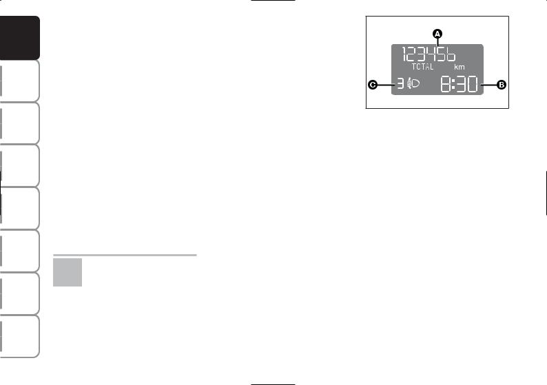
“STANDARD” SCREEN fig. 26
The standard screen shows the following information:
AOdometer (viewing of covered km or miles)
BTime (always displayed, even with ignition key removed and front doors closed)
CHeadlight aiming position (only with dipped beam headlights on).
NOTE When opening one of the front doors, the display turns on and shows the clock and the kilometres or miles covered for a few seconds.
22
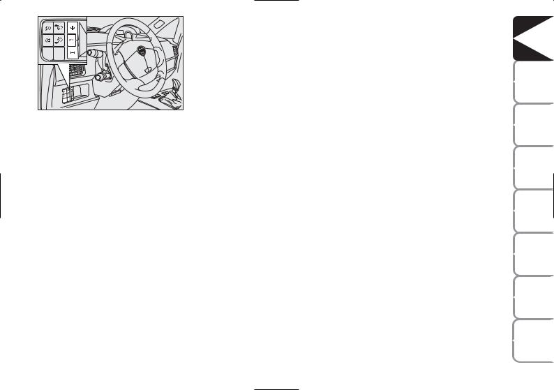
fig. 27 |
L0D0384m |
|
CONTROL BUTTONS fig. 27
+To scroll the next items on the displayed menu and the related options or increase the displayed value.
MODE Press briefly to access the menu and/or go to next screen or confirm the required menu option.
Hold pressed to go back to the standard screen.
–To scroll the previous items on the displayed menu and the related options or reduce the displayed value.
NOTE Buttons + and – activate different functions according to the following situations.
SETUP MENU
The “Setup Menu” is used to make the following settings and/or adjustments:
ADJUSTING THE CLOCK
ADJUSTING THE BUZZER VOLUME
SETTING THE SPEED LIMIT
SETTING THE UNIT
Adjusting the clock
The car is delivered with the clock adjusted for 24 hours.
To set the required time proceed as follows:
press the button MODE several times until the text “Hour” appears;
press the button + to increase the time by one minute;
press the button – to reduce the time by one minute;
Hold the buttons + or – pressed for a few seconds to automatically start quick increase or reduction of the time until the buttons are released.
Press the button MODE and hold it pressed for over 2 seconds to confirm the time change.
Adjusting the buzzer volume
To adjust the desired volume proceed as follows:
press the button MODE several times until the text “bUZZ” appears;
press the button + to increase the volume;
press the button – to reduce the volume;
press the button MODE and hold it pressed for over 2 seconds to confirm the volume change.
Indication that the set peed limit has been exceeded
Proceed as described below to set a reference car speed value beyond which the system warns the driver about this by displaying a message and starting the buzzer.
The car is delivered with this function in “OFF”mode.
DASHBOARD |
AND CONTROLS |
|
SAFETY |
DEVICES |
|
STARTING |
AND |
DRIVING |
WARNING |
LIGHTS AND |
MESSAGES |
IN AN |
EMERGENCY |
|
MAINTENANCE |
AND CARE |
|
TECHNICAL |
SPECIFICATIONS |
|
INDEX |
|
|
23
|
DASHBOARD |
AND CONTROLS |
|
SAFETY |
DEVICES |
STARTING |
AND |
DRIVING |
WARNING |
LIGHTS AND |
MESSAGES |
|
IN AN |
EMERGENCY |
|
MAINTENANCE |
AND CARE |
|
TECHNICAL |
SPECIFICATIONS |
|
|
INDEX |
Set this function as follows:
press the button MODE several times until the text “SPEED” appears;
press the button + to increase the speed value (max. limit being 250 Km/h);
press the button – to reduce the speed value (min. limit being 30 Km/h below which the system goes back to “OFF” mode);
press the button MODE and hold it pressed for over 2 seconds to confirm the speed setting.
Setting the unit
To set the required unit (kilometres or miles) proceed as follows:
press the button MODE several times until the text “Unit” appears;
press the button + or – to change the unit;
press the button MODE and hold it pressed for over 2 seconds to confirm the unit setting.
Viewing of the
fuel cut-off inertial switch tripping
The screen automatically appears whenever the fuel cut-off inertial switch trips after a significant collision.
This switch stops fuel supply.
See the information provided in the dedicated chapter “Fuel cut-off inertial switch”.
WARNING
If, after the message “FPSon” appears, you smell fuel or see leaks from the fuel
supply system, do not reset the switch to avoid the risk of starting a fire.
24
MULTIFUNCTIONAL DISPLAY
(on three-line comfort panel)
The car can be equipped with a multifunction display that shows useful information for car driving according to the settings made.
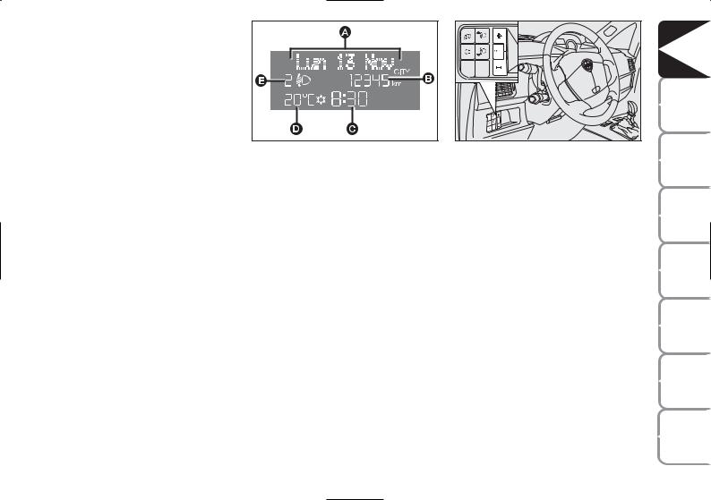
“STANDARD” SCREEN fig. 29
The standard screen shows the following information:
A Date
BOdometer (viewing of covered km or miles)
CTime (always displayed, even with ignition key removed and front doors closed)
fig. 29 |
L0D09000m |
|
D External temperature
EHeadlight aiming position (only with dipped beam headlights on)
NOTE When opening one of the front doors, the display turns on and shows the clock and the kilometres or miles covered for a few seconds.
fig. 30 |
L0C0384m |
|
CONTROL BUTTONS fig. 30
+To scroll the next items on the displayed menu and the related options or increase the displayed value.
MODE Press briefly to access the menu and/or go to next screen or confirm the required menu option.
Hold pressed to go back to the standard screen.
–To scroll the previous items on the displayed menu and the related options or reduce the displayed value.
NOTE Buttons + and – activate different functions according to the following situations.
DASHBOARD |
AND CONTROLS |
|
SAFETY |
DEVICES |
|
STARTING |
AND |
DRIVING |
WARNING |
LIGHTS AND |
MESSAGES |
IN AN |
EMERGENCY |
|
MAINTENANCE |
AND CARE |
|
TECHNICAL |
SPECIFICATIONS |
|
INDEX |
|
|
25

|
DASHBOARD |
AND CONTROLS |
|
SAFETY |
DEVICES |
STARTING |
AND |
DRIVING |
WARNING |
LIGHTS AND |
MESSAGES |
|
IN AN |
EMERGENCY |
|
MAINTENANCE |
AND CARE |
|
TECHNICAL |
SPECIFICATIONS |
|
|
INDEX |
Adjustment of
headlight aiming device (only with dipped beam headlights on)
- when the standard screen is enabled, the headlight aiming device can be regulated (refer to paragraph “Headlights” in this section).
Setup menu
-to scroll the previous and next items in the menu;
-to increase or decrease values during setting operations.
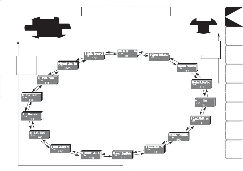
SETUP MENU fig. 31
The menu comprises a series of functions arranged in a cycle which can be selected through buttons + and – to access the different “select” operations and settings (setup) described in the following paragraphs.
The setup menu is activated by pressing briefly button MODE.
Intermittent pressing of buttons + and
– enables scrolling of the setup menu options.
Handling modes are different according to the characteristic of the option selected.
NOTE If the Connect Nav+ system is installed, only the following functions can be adjusted/set from the Instrument Panel: “Brightness”, “Speed Beep”, Light Sensors” (where provided), “Seat belt Buzzer” and “Passenger’s Airbag”. The other functions are displayed on the Connect Nav+ system which is used to adjust/set them.
Selecting a menu option
–Briefly press button MODE to select the menu option that needs to be changed.
–Press buttons + and – (by single pressing) to select the new setting.
–Briefly press button MODE to store the new setting and at the same time go back to the previously selected menu option.
Selecting the “Set Date” and “Set time”
–Briefly press button MODE to select the first value to be changed (e.g. hours /minutes or year / month / day).
–Press buttons + and – (by single pressing) to select the new setting.
–Briefly press button MODE to store the new setting and at the same time go to the next setup menu option. If the processed option is the last one, the system brings you back to the previously selected option of the main menu.
Prolonged pressing of the button MODE enables:
– exiting the setup menu page and saving of the changes already stored by the driver (and confirmed by briefly pressing the button MODE).
The setup menu page is timed. Only the changes saved by the user by briefly pressing MODE are saved when the menu is automatically closed.
26
Example:
Deutsch
Italiano |
English |
|
|
Português |
Español |
|
|
|
Français |
From the standard screen, briefly press button MODE to start browsing. Press + or – to browse within the menu. NOTE Only the short menu may be accessed for reasons of safety while the car is moving (“Brightness” and “Speed Beep” settings). Stop the car to access the full menu. In cars equipped with a Connect Nav+ system, many functions are viewed from the navigator display.
Example:
Day
Year |
Month |
|
|
|
|
|
|
|
|
|
|
|
|
|
|
MODE |
|
|
|
|
|
|
|
|
|
|
+ |
+ |
|
|
|
brief |
button |
|
|
|
|
|
|
+ |
|
– |
|
– |
|
+ |
|
pressing |
|
MODE |
|
|
|
|
|
|
TRIP B |
|
|
|
|
||||
|
|
|
|
– |
LIGHT SENS. |
CLOCK |
SETTING |
|
|
|
|
||||
brief |
button |
|
|
|
|
|
|
|
|
||||||
|
|
+ |
|
|
|
|
– |
|
|
|
|
||||
pressing |
|
|
|
|
|
|
|
|
|
|
|
|
|
||
|
|
|
|
|
– |
SPEED BEEP. |
|
|
|
CLOCK MODE |
– |
+ |
|
||
|
|
|
|
|
|
|
|
|
|
|
|
|
|
|
|
|
|
+ |
– |
|
EXITING THE MENU |
|
|
|
|
|
|
|
|
|
|
|
|
|
|
|
|
|
|
SETTING THE DATE |
|
|
|||||
|
|
|
|
|
|
|
|
|
|
|
+ |
||||
|
|
|
|
|
|
|
|
|
|
|
– |
||||
|
|
|
|
BAG. PASS. |
|
|
|
|
|
|
|
|
|||
|
|
|
|
|
|
|
|
|
|
|
|
|
|
||
+ |
|
|
|
|
|
|
|
|
|
|
|
KEY |
|
|
|
– |
|
|
|
|
|
|
|
|
|
|
– |
|
|
||
|
|
|
|
|
|
|
|
|
|
|
|
+ |
|
||
|
|
|
SERVICE |
|
|
|
|
|
|
|
|
||||
|
|
|
|
|
|
|
|
|
|
|
|
||||
|
|
|
|
|
|
|
|
|
|
|
DIST. |
UNIT |
|
|
|
|
+ |
|
– |
BELT BUZZ. |
|
|
|
|
|
|
|
– |
|
|
|
|
|
|
(*) where provided |
|
|
|
|
|
|
|
|
|
|||
|
|
|
|
|
|
|
|
|
|
CONSUMPTION |
|
+ |
|
|
|
|
|
|
|
– |
VOL. BUTTONS |
|
|
|
TEMP. UNIT |
– |
|
|
|
|
|
|
|
|
+ |
|
|
|
|
|
|
(*) This function may only |
|||||
|
|
|
|
|
VOL. BUZZER |
|
LANGUAGE |
|
+ |
|
|||||
|
|
|
|
|
|
– |
|
– |
|
– |
|
|
be displayed after the SBR |
||
|
fig. 31 |
|
|
|
|
|
|
|
system is deactivated by a |
||||||
|
|
|
|
|
|
|
|
|
|
||||||
|
|
|
|
|
|
+ |
|
+ |
|
+ |
|
|
Lancia Dealership. |
|
|
|
|
|
|
|
|
|
|
|
|
|
|
|
|||
|
|
|
|
|
|
|
|
|
|
|
|
|
|
|
|
SAFETY |
DEVICES |
|
STARTING |
AND |
DRIVING |
WARNING |
LIGHTS AND |
MESSAGES |
IN AN |
EMERGENCY |
|
MAINTENANCE |
AND CARE |
|
TECHNICAL |
SPECIFICATIONS |
|
INDEX |
|
|
27

|
DASHBOARD |
AND CONTROLS |
|
SAFETY |
DEVICES |
STARTING |
AND |
DRIVING |
WARNING |
LIGHTS AND |
MESSAGES |
|
IN AN |
EMERGENCY |
|
MAINTENANCE |
AND CARE |
|
TECHNICAL |
SPECIFICATIONS |
|
|
INDEX |
Speed limit (Speed beep)
This function enables setting of the car speed limit (km/h or mph). When this limit is exceeded the driver is immediately alerted (see section “Warning lights and messages”).
To set the speed limit, proceed as follows:
–briefly press button MODE: the display will show the wording “Speed Beep”;
–press button + or – to select speed limit activation (On) or deactivation (Off);
–if the function is on, press buttons + or – to select the required speed limit and then press MODE to confirm.
NOTE The speed may be set in the range from 30 to 250 km/h, or from 20 to 155 mph according to the previously chosen unit (see “Setting the distance unit”) described below. The setting will increase/decrease by 5 units each time button + / – is pressed. Hold button +/– pressed to increase/decrease the setting rapidly. Complete the setting by briefly pressing the button when you approach the required value.
– briefly press button MODE to go back to the menu screen or press the button for a prolonged time to go back to the standard screen without storing the settings.
To cancel the setting, proceed as follows:
–briefly press button MODE: ON flashes on the display;
–press button +: OFF flashes on the display;
–briefly press button MODE to go back to the menu screen or press the button for a prolonged time to go back to the standard screen without storing the settings.
28

Adjusting the sensitivity of the automatic headlight sensor (Light sensor) (where provided)
This function is used to adjust the dusk sensor sensitivity according to three levels (level 1 = minimum, level 2 = medium, level 3 = maximum); the higher the sensitivity, the lower the quantity of external light needed to switch the headlights on. The car is delivered with this function set to level “2”.
To change this setting:
–briefly press button MODE: the previously set level flashes on the display;
–press button + or – for selecting the desired level;
–briefly press button MODE to go back to the menu screen or press the button for a prolonged time to go back to the standard screen without storing the settings.
Trip B On/Off (Trip B)
Through this option it is possible to activate (On) or deactivate (Off) the Trip B (partial trip) display.
For further information see section “Trip computer”.
For activation / deactivation, proceed as follows:
–briefly press button MODE: ON or OFF flashes on the display (according to previous setting);
–press button + or – for selecting the desired value;
–briefly press button MODE to go back to the menu screen or press the button for a prolonged time to go back to the standard screen without storing the settings.
Setting the clock (Set time)
This function enables setting of the clock.
To set the clock proceed as follows:
–briefly press button MODE: the display shows the “hours” flashing;
–press button + or – to set the clock;
–briefly press button MODE: “minutes”starts flashing on the display;
–press button + or – to set the clock.
NOTE The setting increases or decreases by one unit each time button + or – is pressed. Hold the button pressed to automatically start a quick increase/decrease of the set value.
Complete the setting by briefly pressing the button when the required setting is approached.
– briefly press button MODE to go back to the menu screen or press the button for a prolonged time to go back to the standard screen without storing the settings.
DASHBOARD |
AND CONTROLS |
|
SAFETY |
DEVICES |
|
STARTING |
AND |
DRIVING |
WARNING |
LIGHTS AND |
MESSAGES |
IN AN |
EMERGENCY |
|
MAINTENANCE |
AND CARE |
|
TECHNICAL |
SPECIFICATIONS |
|
INDEX |
|
|
29
 Loading...