

Page 1
OPTISWITCH 4000/5000
Technical Datasheet
Vibration level switches for liquids
• Operates up to 250°C / 480°F and 64 bar / 925 psi
• Pump dry-run detection
• High reliability due to permanent fault monitoring function
Page 2
OPTISWITCH 4000/5000 nnnnnnnnnnnnnnnnnnnnnnnnnnnnnnnnnnnnnnnnnnnnnnnnn
n
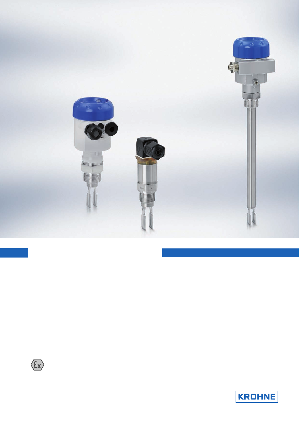
Universal liquid level switches
OPTISWITCH 4000/5000 series is a level sensor that uses a vibrating fork for detecting level. It is designed for
use in all liquids. It is not affected by foam and external vibration. It is also unaffected by variations of product
properties such as ε
1 OPTISWITCH 4000
2 OPTISWITCH 5100
3 OPTISWITCH 5200
, viscosity etc.
r
Highlights
• Output options: relay, transistor, NAMUR,
contactless electronic switch and 2-wire
• 5000 series: Plastic, aluminium or stainless
steel housings
• LED signal lamp for indicating the switching
condition (with plastic housing only)
• 5000 series: Large choice of materials for
wetted parts. This includes 316L, Hastelloy C4,
enamel, ECTFE and PFA.
• 5000 series. Probe length: 53...6000 mm /
2...236"
• Repeatability: +/-2 mm
• Thread connections G/NPT ¾; flange sizes from
DN25 PN40; Triclamp 1" or 2" and other
hygienic fittings
Industries
• Chemicals
• Food & Beverage
• Water & Wastewater
• Oil & Gas
Applications
• Reactors
• Hygienic and sanitary applications
• Process and storage tanks for liquids
• Dry-run and overfill protection
2
www.krohne.com
Page 3
Features and Options
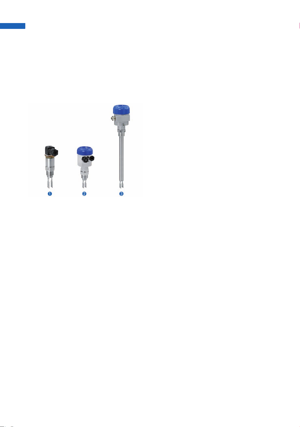
OPTISWITCH 4000 - The economical
version
Simple and robust measuring system, virtually
•
unaffected by the chemical and physical
properties of liquids
• Easily mountable in pipelines from DN 25,
vessels and tanks
• Outputs: contactless electronic switch or
transistor
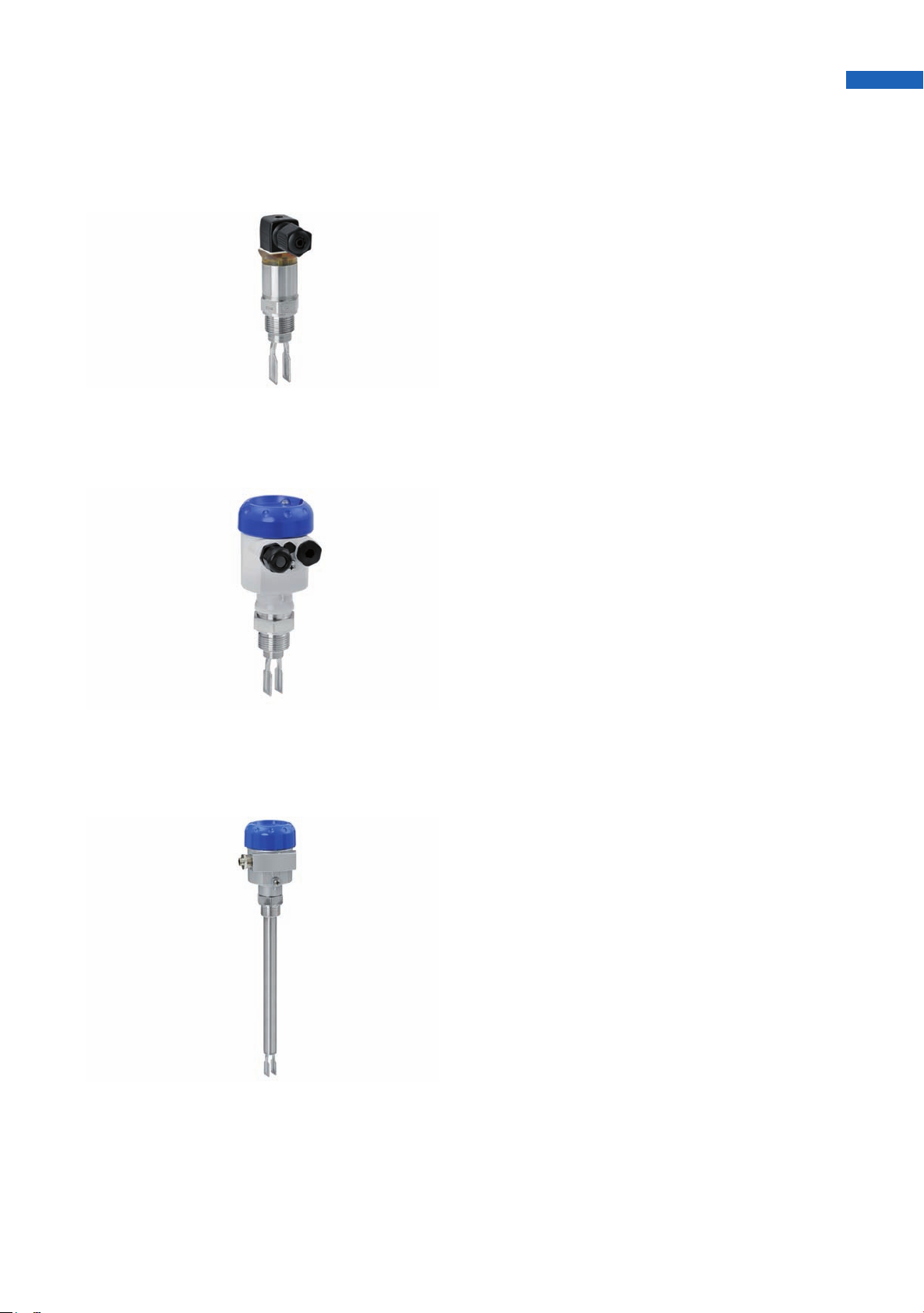
OPTISWITCH 5100, 5150 - The compact
version
• Standard or HT version, large array of process
fittings, housings and electronics
• Outputs: relay, transistor, 2wire, NAMUR or
contactless electronic switch
• Process connection option for high temperature
up to 250°C / 482°F
• With all relevant approvals (ATEX etc.)
• Version OPTISWITCH 5150 with polished tuning
fork e.g. for food processing
OPTISWITCH 5200, 5250 - The special
version with probe extension
• Standard or HT version, large array of process
fittings, housings and electronics
• Probe length up to 6000 mm / 236"
• Outputs: relay, transistor, 2wire, NAMUR or
contactless electronic switch
• Process connection option for high temperature
up to 250°C / 482°F
• With all relevant approvals (ATEX etc.)
• Version OPTISWITCH 5150 with polished tuning
fork e.g. for food processing
www.krohne.com
3
Page 4

OPTISWITCH 4000/5000 nnnnnnnnnnnnnnnnnnnnnnnnnnnnnnnnnnnnnnnnnnnnnnnnn
n
Technical data
OPTISWITCH 4000 C
Function
Measurement parameter Level detection of liquids
Measurement accuracy
Hysteresis Approx. 2 mm / 0.08" with vertical installation
Integration time Approx. 500 ms
Frequency Approx. 1200 Hz
Operating conditions
Temperature
Temperature
TemperatureTemperature
Ambient temperature on housing -40…+70°C / -40…+158°F
Storage and transport temperature -40…+80°C / -40…+176°F
Process temperature
Process temperature
Process temperatureProcess temperature
Standard -40…+100°C / -40…+212°F
High temperature version (optional) -40…+150°C / -40…+302°F
Temperature shock No limitation
Process pressure -1…64 bar / -14.5…928 psi
Viscosity (dynamic) 0.1...10.000 mPa s (requirement: with SG=1)
Density
>0.7 g/cm2 / >0.025 lbs/in
2
Materials
Wetted parts
Wetted parts
Wetted partsWetted parts
Process fitting – thread 316L
Gaskets Klingersil C-4400
Vibrating element 316L
Non-wetted parts
Non-wetted parts
Non-wetted partsNon-wetted parts
Housing 316L and plastic PEI
Surface quality
Surface quality
Surface qualitySurface quality
Standard
Hygienic version
Ra = approx. 3.2 μm / 1.26-4"
Ra < 0.8 μm / 3.15-5"
Process connection
Thread G¾ A; ¾ NPT; G1 A; 1 NPT
Hygienic fittings Bolting DN 25 PN 40; bolting DN 40 PN 40; Tri-Clamp 1"; Tri-Clamp 1½";
SMS
4
www.krohne.com
Page 5

Power Supply
Transistor output
Transistor output
Transistor outputTransistor output
Supply voltage 10…55 VDC
Power consumption Max. 0.5 W
Contactless electronic switch
Contactless electronic switch
Contactless electronic switchContactless electronic switch
Supply voltage 20…253 VAC, 50/60 Hz, 20…253 VDC
Power consumption Approx. 3 mA (via load circuit)
Operating elements
Operating elements
Operating elementsOperating elements
Control lamp Illuminated lens for indication of the switching condition.
Mode adjustment Min./max. adjustment through electrical connection
Electromechanical data
Electromechanical data
Electromechanical dataElectromechanical data
Plug connection 1x plug M12x1 or 1x plug DIN 43650
Screwed terminals For wire cross-section up to 1.5 mm²
Output
Transistor output
Transistor output Floating transistor output, overload and permanently shortcircuit-proof
Transistor outputTransistor output
Load current Max. 250 mA
Voltage loss Max. 1 V
Turn-on voltage Max. 55 VDC
Blocking current <10 μA
Modes (adjustable) Min. / max.
Delay time When immersed: approx. 0.5 s; when uncovered: approx. 1 s
Contactless electronic switch
Contactless electronic switch Contactless electronic switch
Contactless electronic switchContactless electronic switch
Modes (adjustable) Min. / max.
Delay time When immersed: approx. 0.5 s; when uncovered: approx. 1 s
Approvals
Protection category
Protection category
Protection categoryProtection category
Valve plug IP 65
Valve plug with IDC method of
termination
M12x1 plug connection (only with
transistor output)
Overvoltage category III
Protection class
Protection class
Protection classProtection class
Transistor output II
Contactless electronic switch I
CE conformity
CE conformity
CE conformityCE conformity
EMC (89/336/EEC) Emission EN 61326: 1997 (class B), immunity EN 61326: 1997/A1: 1998
LVD (73/23/EEC) EN 61010-1: 2001
SIL conformity OPTISWITCH fulfills the requirements of functional safety according to
IP 67
IP 66/IP 67
IEC 61508.
www.krohne.com
5
Page 6

OPTISWITCH 4000/5000 nnnnnnnnnnnnnnnnnnnnnnnnnnnnnnnnnnnnnnnnnnnnnnnnn
n
OPTISWITCH 5000 C series
Function
Measurement parameter Level detection of liquids
Design
Sensor length
Sensor length
Sensor lengthSensor length
OPTISWITCH 5100 C, 5150 C See chapter "Dimensions".
OPTISWITCH 5200 C, 5250 C
316L, 2.4610 (Hastelloy C4) 80...6000 mm / 3...236"
2.4610 (Hastelloy C4) enamelled 80...1500 mm / 3...59"
1.4435 (316L) ECTFE coated 80...3000 mm / 3...118"
1.4435 (316L) PFA coated 80...3000 mm / 3...118"
Measurement accuracy
Hysteresis Approx. 2 mm / 0.08" with vertical installation
Integration time Approx. 500 ms
Frequency Approx. 1200 Hz
Operating conditions
Temperature
Temperature
TemperatureTemperature
Ambient temperature on housing -40…+70°C / -40…+158°F
Storage and transport temperature -40…+80°C / -40…+176°F
Process temperature
Process temperature
Process temperatureProcess temperature
316L / Hastelloy C4 (2.4610) -50…+150°C / -58…+302°F
Process temperature with temperature
adapter
316L / Hastelloy C4 (2.4610) -50…+250°C / -58…+482°F
enamelled -50…+200°C / -58…+392°F
with ECTFE coating -50…+150°C / -58…+302°F
with PFA coating -50…+150°C / -58…+302°F
Temperature shock No limitation
Process pressure -1…64 bar / -14.5…928 psi
Viscosity (dynamic) 0.1...10.000 mPa s (requirement: with SG=1)
Density
Option
0.7...2.5 g/cm2 / 0.025...0.09 lbs/in2; 0.5...2.5 g/cm2 / 0.018...0.09 lbs/in2 by
switching over
6
www.krohne.com
Page 7

Materials
Wetted parts
Wetted parts
Wetted partsWetted parts
Process fitting – thread 316L; 2.4602 (Hastelloy C4)
Process fitting – flange 316L; 316L with Hastelloy C4 coating; steel enamelled; 316L with ECTFE
Gaskets Klingersil C-4400
Tuning fork 316L / 2.4610 (Hastelloy C4)
Extension tube ø21.3 mm / ø0.84" 316L; 2.4610 (Hastelloy C4); 2.4610 (Hastelloy C4) enamelled; 316L with
Non-wetted parts
Non-wetted parts
Non-wetted partsNon-wetted parts
Housing Plastic PBT (Polyester), Alu-die casting powder-coated, 316L
Gasket ring between housing and
housing cover
Peephole in housing cover PMMA (Makrolon)
Ground terminal 316L
Temperature adapter (Option) 316L
Gastight leadthrough (Option) 316L / glass
Surface quality
Surface quality
Surface qualitySurface quality
Standard (OPTISWITCH 5100 C, 5200 C) Ra = approx. 3.2 μm / 1.26-4"
Hygienic version
(OPTISWITCH 5150 C, 5250 C)
Coatings
Coatings
CoatingsCoatings
ECTFE Approx. 0.5…0.8 mm / 0.02…0.03"
PFA Approx. 0.3…0.5 mm / 0.01…0.02"
Enamel Approx. 0.8 mm / 0.03"
coating; 316L with PFA coating
ECTFE coating; 316L with PFA coating
NBR (stainless steel housing), silicone (Alu / plastic housing)
Ra < 0.8 μm / 3.15-5"
Process connection
Thread G¾ A; ¾ NPT; G1 A; 1 NPT
Flanges DIN: ≥DN25; ANSI: ≥1"
Hygienic fittings (OPTISWITCH 5150 C,
5250 C)
Bolting DN 40 PN 40; Tri-Clamp 1"; Tri-Clamp 1½" PN 10; cone DN 25 PN
40; Tuchenhagen Varivent DN 50 PN 10
Power Supply
Relay output
Relay output
Relay outputRelay output
Supply voltage 20…253 VAC, 50/60 Hz, 20…72 VDC (at U >60 VDC, the ambient temperature
Power consumption 1…8 VA (AC); ca. 1.3 W (DC)
Transistor output
Transistor output
Transistor outputTransistor output
Supply voltage 10…55 VDC
Power consumption Max. 0.5 W
Contactless electronic switch
Contactless electronic switch
Contactless electronic switchContactless electronic switch
Supply voltage 20…253 VAC, 50/60 Hz, 20…253 VDC
Power consumption Approx. 3 mA (via load circuit)
can be max. 50°C / 122°F)
www.krohne.com
7
Page 8

OPTISWITCH 4000/5000 nnnnnnnnnnnnnnnnnnnnnnnnnnnnnnnnnnnnnnnnnnnnnnnnn
n
Two-wire output
Two-wire output
Two-wire outputTwo-wire output
Supply voltage 10…36 VDC (via the signal conditioning instrument)
NAMUR output
NAMUR output
NAMUR outputNAMUR output
Supply voltage (standard
characteristics)
Open-circuit voltage U0 approx. 8.2 V
Shortcircuit current IU approx. 8.2 mA
Operating elements
Control lamp Control lamp (LED) for indication of the switching condition.
Density switch (electronics versions: relay, transistor, contactless electronic switch, two-wire, NAMUR outputs)
0.5
0.7
Mode switch (electronics versions: relay output, transistor output, contactless electronic switch)
A Max. detection or overfill protection
B Min. detection or dry run protection
Characteristics reversal (electronics version: NAMUR output)
Max. Falling characteristics (Low current when immersed)
Min. Rising characteristics (High current when immersed)
Electromechanical data
Cable entry/plug (dependent on the
version) - Single chamber housing
Screwed terminals For wire cross-section up to 1.5 mm²
For connection to amplifier according to NAMUR IEC 60947-5-6, approx.
8.2 V
0.5...2.5 g/cm2 / 0.018...0.9 oz/in
0.7...2.5 g/cm2 / 0.025...0.9 oz/in
1x cable entry M20x1.5 (cable ø5…9 mm), 1x blind stopper M20x1.5;
attached 1x cable entry M20x1.5 or 1x cable entry ½ NPT, 1x blind stopper
½ NPT, 1x cable entry ½ NPT
2
2
Output
Relay output
Relay output Relay output (DPDT), 2 floating spdts
Relay outputRelay output
Turn-on voltage Min.: 10 mV; max.: 253 VAC/DC
Switching current Min.: 10 μA; max.: 5 A AC, 1 A DC
Breaking capacity Max.: 1250 VA, 50 W
Contact material (relay contacts) AgCdO and Au plated
Modes (adjustable) Min. / max.
Delay time When immersed: approx. 0.5 s; when uncovered: approx. 1 s
Transistor output
Transistor output Floating transistor output, overload and permanently shortcircuit proof
Transistor outputTransistor output
Load current Max. 400 mA
Voltage loss Max. 1 V
Turn-on voltage Max. 55 VDC
Blocking current <10 μA
Modes (adjustable) Min. / max.
Delay time When immersed: approx. 0.5 s; when uncovered: approx. 1 s
Contactless electronic switch
Contactless electronic switch Contactless electronic switch
Contactless electronic switchContactless electronic switch
Modes (adjustable) Min. / max.
Delay time When immersed: approx. 0.5 s; when uncovered: approx. 1 s
8
www.krohne.com
Page 9

Two-wire output
Two-wire output
Two-wire outputTwo-wire output
Suitable signal conditioning instruments SU 501
Output signal
Min. mode Vibrating element uncovered: 16 mA ±1 mA; vibrating element covered:
8mA±1mA
Max. mode Vibrating element uncovered: 8 mA ±1 mA; vibrating element covered:
16 mA ±1mA
Fault signal <2 mA
Modes (adjustable) Min. / max. (changeover with the signal conditioning instrument)
Delay time When immersed: approx. 0.5 s; when uncovered: approx. 1 s
NAMUR output
NAMUR output Two-wire NAMUR output
NAMUR outputNAMUR output
Current consumption
Falling characteristics ≥2.2 mA uncovered / ≤1 mA covered
Rising characteristics ≤1 mA uncovered / ≥2.2 mA covered
Fault signal ≤1 mA
Necessary processing system NAMUR processing system according to IEC 60947-5-6
(EN 50227/DIN 19234)
Modes (NAMUR output adjustable to
falling or rising characteristics)
Min.: rising characteristics (High current when immersed); max.: falling
characteristics (Low current when immersed)
Approvals
ATEX ATEX II 1G, 1/2G, 2G EEx ia IIC T6 1
ATEX II 1/2G, 2G EEx d IIC T6 2
ATEX II 1/2D IP6X T
Ship approval GL & LR
WHG German Federal Water Act 3
Protection category IP 66/IP 67
Overvoltage category III
Protection class
Protection class
Protection classProtection class
Transistor output, two-wire output,
NAMUR output
Relay output, contactless electronic
switch
CE conformity
CE conformity
CE conformityCE conformity
EMC (89/336/EEC) Emission EN 61326/A1: 1998 (class B), susceptibility EN 61326: 1997/A1:
LVD (73/23/EEC) EN 61010-1: 1993
SIL conformity OPTISWITCH fulfills the requirements of functional safety according to
1 this approval is for 2-wire and NAMUR electronics. It can be combined with either WHG or with ship approval.
2 only for the plastic-coated aluminium housing with a ½ NPT cable gland. An optional temperature adapter can be used without a gas-
tight bushing.
3 only for contactless electronic switch, relay and transistor electronics.
II
I
1998
IEC 61508.
www.krohne.com
9
Page 10

OPTISWITCH 4000/5000 nnnnnnnnnnnnnnnnnnnnnnnnnnnnnnnnnnnnnnnnnnnnnnnnn
n
Dimensions and Weights
OPTISWITCH 4000 - Standard version:
From left to right: thread (M12x1, valve plug DIN 43650 and valve plug DIN 43650 with IDC
method of termination)
1 M12x1
2 Thread G¾ A, G1 A, ¾ NPT, 1 NPT
3 Switching point
10
www.krohne.com
Page 11

Dimensions in mm
a b c d e f g h L
[mm]
Thread G¾ A, G1 A, ¾ NPT or
1NPT (M12x1)
Thread G¾ A, G1 A, ¾ NPT or
1 NPT (valve plug DIN 43650)
Thread G¾ A,G1 A, ¾ NPT or
1 NPT(valve plug DIN 43650 with
IDC method of termination)
1 with G¾ A, ¾ NPT: 66 mm; with G1 A, 1 NPT: 69 mm
132.5 10.0 WS 32 - - 21.3 13.0 40.0 L 1
158.0 35.0 - 27.0 36.0 - - - -
165.0 42.0 - 28.0 42.0 - - - -
Dimensions in inches
a b c d e f g h L
Thread G¾ A, G1 A, ¾ NPT or 1
NPT (M12x1)
Thread G¾ A, G1 A, ¾ NPT or
1 NPT (valve plug DIN 43650)
Thread G¾ A, G1 A, ¾ NPT or
1 NPT(valve plug DIN 43650 with
IDC method of termination)
1 with G¾ A, ¾ NPT: 2.6"; with G1 A, 1 NPT: 2.7"
5.22 0.39 WS 32 - - 0.84 0.51 1.57 L 1
6.22 1.38 - 1.06 1.42 - - - -
6.50 1.65 - 1.10 1.65 - - - -
[inches]
www.krohne.com
11
Page 12

OPTISWITCH 4000/5000 nnnnnnnnnnnnnnnnnnnnnnnnnnnnnnnnnnnnnnnnnnnnnnnnn
n
OPTISWITCH 4000 - Hygienic version:
From left to right: Tri-Clamp (valve plug DIN 43650); Bolting (valve plug DIN 43650);
SMS 1145 (valve plug DIN 43650)
1 Switching point
12
www.krohne.com
Page 13

DImensions in mm
a b c L
[mm]
Tri-Clamp (valve plug DIN 43650) 101.0 13.0 40.0 L 1
Bolting (valve plug DIN 43650) 115.0 - - L 1
SMS 1145 (valve plug DIN 43650) 105.0 - - L 1
1 53 mm
Dimensions in inches
a b c L
[inches]
Tri-Clamp (valve plug DIN 43650) 3.98 0.51 1.57 L 1
Bolting (valve plug DIN 43650) 3.53 - - L 1
SMS 1145 (valve plug DIN 43650) 4.13 - - L 1
1 2.1"
www.krohne.com
13
Page 14

OPTISWITCH 4000/5000 nnnnnnnnnnnnnnnnnnnnnnnnnnnnnnnnnnnnnnnnnnnnnnnnn
n
OPTISWITCH 4000 - High temperature version:
From left to right: thread (M12x1, valve plug DIN 43650 and valve plug DIN 43650 with IDC
method of termination)
1 M12x1
2 Thread G¾ A, G1 A, ¾ NPT, 1 NPT
3 Switching point
www.krohne.com
14
Page 15

Dimensions in mm
a b c d e f g h L
[mm]
Thread G¾ A, G1 A, ¾ NPT or
1NPT (M12x1)
Thread G¾ A, G1 A, ¾ NPT or
1 NPT (valve plug DIN 43650)
Thread G¾ A, G1 A, ¾ NPT or
1 NPT (valve plug DIN 43650 with
IDC method of termination)
1 with G¾ A, ¾ NPT: 66 mm; with G1 A, 1 NPT: 69 mm
162.5 10.0 WS 32 - - 21.3 13.0 40.0 L 1
188.0 35.0 - 27.0 36.0 - - - -
182.0 42.0 - 28.0 42.0 - - - -
Dimensions in inches
a b c d e f g h L
Thread G¾ A, G1 A, ¾ NPT or
1NPT (M12x1)
Thread G¾ A, G1 A, ¾ NPT or
1 NPT (valve plug DIN 43650)
Thread G¾ A, G1 A, ¾ NPT or
1 NPT (valve plug DIN 43650 with
IDC method of termination)
1 with G¾ A, ¾ NPT: 2.6"; with G1 A, 1 NPT: 2.7"
6.40 0.39 WS 32 - - 0.84 0.51 1.57 L 1
7.40 1.38 - 1.06 1.42 - - - -
7.15 1.65 - 1.10 1.65 - - - -
[inches]
www.krohne.com
15
Page 16

OPTISWITCH 4000/5000 nnnnnnnnnnnnnnnnnnnnnnnnnnnnnnnnnnnnnnnnnnnnnnnnn
n
OPTISWITCH 5000 series - Housing
From left to right: Plastic, Stainless steel and Aluminium housing
1 M20x1,5 / ½ NPT
2 M20x1,5
Dimensions and Weights
Dimensions Weight Dimensions Weight
[mm] [kg] [inches] [lbs]
a b c a b c
Plastic Housing 69 Ø77 112 0.76 2.72 Ø3.0 4.41 1.68
Stainless steel housing 69 Ø77 117 1.53 2.72 Ø3.0 4.61 3.37
Aluminium housing 116 84 114 1.17 4.57 3.31 4.49 2.58
16
www.krohne.com
Page 17

OPTISWITCH 5100 C, 5150 C, 5200 C, 5250 C - Temperature adapter
Dimensions in mm and inches
a b a b
[mm] [inches]
Temperature adapter 178 Ø34 7 Ø1.34
www.krohne.com
17
Page 18

OPTISWITCH 4000/5000 nnnnnnnnnnnnnnnnnnnnnnnnnnnnnnnnnnnnnnnnnnnnnnnnn
n
OPTISWITCH 5100 C, 5150 C
c
b
a
d
123
b
a
b
b
a
e
b
a
1 Thread
2 Tri-Clamp (OPTISWITCH 5150)
3 Cone DN 25 (OPTISWITCH 5150)
4 Bolting DN 40 (OPTISWITCH 5150)
5 Flange
6 Gas-tight leadthrough
7 Temperature adapter
4
b
a
5
b
7
6
18
www.krohne.com
Page 19

Dimensions in mm
a b c d
[mm]
Thread 66 18.5 WS 32 (G¾A;
¾ NPT); WS 41
(G1A; 1 NPT)
Tri-Clamp (OPTISWITCH 5150) 53 36 - Cone DN 25 (OPTISWITCH 5150) 55 57 - Bolting DN 40 (OPTISWITCH 5150) 53 50 Ø33.7 Flange 53 19 - Gas-tight leadthrough - 34 - Temperature adapter - 178 - -
G¾A, ¾ NPT;
G1A, 1 NPT
Dimensions in inches
a b c d
[inches]
Thread 2.6 0.72 WS 32 (G¾A;
¾ NPT); WS 41
(G1A; 1 NPT)
Tri-Clamp (OPTISWITCH 5150) 2.09 1.41 - Cone DN 25 (OPTISWITCH 5150) 2.17 2.24 - Bolting DN 40 (OPTISWITCH 5150) 2.09 1.97 Ø1.33 Flange 2.09 0.75 - Gas-tight leadthrough - 1.34 - Temperature adapter - 7.0 - -
G¾A, ¾ NPT;
G1A, 1 NPT
www.krohne.com
19
Page 20

OPTISWITCH 4000/5000 nnnnnnnnnnnnnnnnnnnnnnnnnnnnnnnnnnnnnnnnnnnnnnnnn
n
OPTISWITCH 5200 C, 5250 C
1 Thread
2 Tri-Clamp (OPTISWITCH 5250)
3 Cone DN 25 (OPTISWITCH 5250)
4 Bolting DN 40 (OPTISWITCH 5250)
5 Flange
6 Gas-tight leadthrough
7 Temperature adapter
www.krohne.com
20
Page 21

Dimensions in mm
a b c d
[mm]
Thread L 1 18.5 WS 32 (G¾A;
¾ NPT); WS 41
(G1A; 1 NPT)
Tri-Clamp (OPTISWITCH 5250) L 1 36 - Cone DN 25 (OPTISWITCH 5250) L 1 57 - Bolting DN 40 (OPTISWITCH 5250) L 1 50 Ø33.7 Flange L 1 19 - Gas-tight leadthrough - 34 - Temperature adapter - 178 - -
1 Ordered sensor length
G3/4A, ¾ NPT;
G1A, 1 NPT
Dimensions in inches
a b c d
[inches]
Thread L 1 0.72 WS 32 (G¾A;
¾ NPT); WS 41
(G1A; 1 NPT)
Tri-Clamp (OPTISWITCH 5250) L 1 1.41 - Cone DN 25 (OPTISWITCH 5250) L 1 2.24 - Bolting DN 40 (OPTISWITCH 5250) L 1 1.97 Ø1.33 Flange L 1 0.75 - Gas-tight leadthrough - 1.34 - Temperature adapter - 7.0 - -
1 Ordered sensor length
G¾A, ¾ NPT;
G1A, 1 NPT
www.krohne.com
21
Page 22

OPTISWITCH 4000/5000 nnnnnnnnnnnnnnnnnnnnnnnnnnnnnnnnnnnnnnnnnnnnnnnnn
n
Notes
22
www.krohne.com
Page 23

Notes
www.krohne.com
23
Page 24

OPTISWITCH 4000/5000 nnnnnnnnnnnnnnnnnnnnnnnnnnnnnnnnnnnnnnnnnnnnnnnnn
n
KROHNE Product Overview
• Electromagnetic flowmeters • Level measuring instruments
• Variable area flowmeters • Pressure gauges
• Mass flowmeters • Temperature measuring instruments
• Ultrasonic flowmeters • Water solutions & analysis
• Vortex flowmeters • Oil and gas turnkey solutions
• Flow controllers
Addresses:
Great Britain
Germany
Northern sales office
KROHNE Messtechnik GmbH & Co. KG
Bremer Str. 133
D-21073 Hamburg
Phone:+49 (0)40 767 3340
Fax:+49 (0)40 767 33412
nord@krohne.de
ZIP code: 10000 - 29999, 49000 - 49999
Western and middle sales office
KROHNE Messtechnik GmbH & Co. KG
Ludwig-Krohne-Straße
D-47058 Duisburg
Phone:+49 (0)203 301 416
Fax:+49 (0)203 301 10416
west@krohne.de
ZIP code: 30000 - 34999, 37000 48000, 50000 - 53999, 57000 - 59999,
98000 - 99999
Southern sales office
KROHNE Messtechnik GmbH & Co. KG
Landsberger Str. 392
D-81241 Munich
Phone:+49 (0)89 121 5620
Fax:+49 (0)89 129 6190
sued@krohne.de
ZIP code: 0 - 9999, 80000 - 89999,
90000 - 97999
Southwestern sales office
KROHNE Messtechnik GmbH & Co. KG
Rüdesheimer Str. 40
D-65239 Hochheim/Main
Phone: +49(0)6146) 827 30
Fax:+49 (0)6146 827 312
rhein-main@krohne.de
ZIP code: 35000 - 36999, 54000 56999, 60000 - 79999
Instrumentation and control
equipment catalog
TABLAR Messtechnik GmbH
Ludwig-Krohne-Straße 5
D-47058 Duisburg
Phone:+49 (0)2 03 305 88 0
Fax:+49 (0)2 03 305 8888
kontakt@tablar.de www.tablar.de
KROHNE sales
companies
International
Australia
Australia
AustraliaAustralia
KROHNE Australia Pty Ltd
Quantum Business Park 10/287
Victoria Rd Rydalmere NSW 2116
Phone: +61 2 8846 1700
Fax: +61 2 8846 1755
krohne@krohne.com.au
Austria
Austria
AustriaAustria
KROHNE Gesellschaft m.b.H.
Modecenterstraße 14
A-1030 Vienna
Phone:+43 (0)1/203 45 32
Fax:+43 (0)1/203 45 32 99
info@krohne.at
Belgium
Belgium
Belgium Belgium
KROHNE Belgium N.V.
Brusselstraat 320
B-1702 Groot Bijgaarden
Phone:+32 (0)2 4 66 00 10
Fax:+32 (0)2 4 66 08 00
krohne@krohne.be
Brazil
Brazil
Brazil Brazil
KROHNE Conaut Controles
Automaticos Ltda.
Estrada Das Águas Espraiadas, 230
C.P. 56 06835 - 080 EMBU - SP
Phone:+55 (0)11-4785-2700
Fax:+55 (0)11 4785-2768
conaut@conaut.com.br
China
China
ChinaChina
KROHNE Measurement Instruments
(Shanghai) Co. Ltd., (KMIC)
Room 1501
1033 Zhaojiabang Ro ad
Shanghai 200030
Phone: +86 21 6487 9611
Fax:+86 21 6438 7110
info@krohne-asia.com
Czech Republic
Czech Republic
Czech RepublicCzech Republic
Krohne CZ, spol. s r.o.
Sobìsická 156
63800 Brno
Phone: +420 (0)545.242 627
Fax: +420 (0)545 220 093
brno@krohne.cz
France
France
FranceFrance
KROHNE S.A.S.
Les Ors BP 98
F-26103 ROMANS Cedex
Phone:+33 (0)4 75 05 44 00
Fax:+33 (0)4 75 05 00 48
info@krohne.fr
Great Britain
Great BritainGreat Britain
KROHNE Ltd.
Rutherford Drive
Park Farm Industrial Estate
Wellingborough
Northants NN8 6AE
Phone:+44 (0)19 33 408 500
Fax:+44 (0)19 33 408 501
info@krohne.co.uk
CIS
CIS
CISCIS
Kanex KROHNE Engineering AG
Business-Centre Planeta
Office 404 ul.
Marxistskaja 3
109147 Moscow/Russia
Phone:+7 (0)095 911 7165
Fax:+7 (0)095 742 8873
krohne@dol.ru
India
India
IndiaIndia
Krohne Marshall Ltd.
A-34/35, M.I.D.C. Industrial Area,
H-Block
Pimpri Poona 411018
Phone:+91 (0)202 744 2020
Fax:+91 (0)202 744 2020
pcu@vsnl.net
Iran
Iran
IranIran
KROHNE Liaison Office
North Sohrevardi Ave. 26,
Sarmad St., Apt. #9
Tehran 15539
Phone: +9821 8874 5973
Fax: +9821 8850 1268
krohne@krohneiran.com
Italy
Italy
ItalyItaly
KROHNE Italia Srl.
Via V. Monti 75
I-20145 Milan
Phone:+39 02 4300 661
Fax:+39 02 4300 6666
info@krohne.it
Korea
Korea
KoreaKorea
KROHNE Korea
Room 508 Miwon Bldg 43
Yoido-Dong Youngd eungpo-Ku
Seoul, Korea
Phone: 00-82-2-782-1900
Fax: 00-82-2-780-1749
mail@krohne.co.kr
Netherlands
Netherlands
NetherlandsNetherlands
KROHNE Nederland B.V.
Kerkeplaat 14
NL-3313 LC Dordrecht
Phone:+31 (0)78 630 6200
Fax:+31 (0)78 630 6405
Service Direct: +31 (0)78 630 6222
info@krohne.nl
Norway
Norway
NorwayNorway
KROHNE Norway A.S.
Ekholtveien 114
NO-1521 Moss
Phone:+47 (0)69 264 860
Fax:+47 (0)69 267 333
postmaster@krohne.no
Poland
Poland
PolandPoland
KROHNE Polska Sp.z.o.o.
ul. Stary Rynek Oliwski 8a
80-324 Gdansk
Phone: +48 (0)58 520 9211
Fax.:+48 (0)58 520 9212
info@krohne.pl
Switzerland
Switzerland
SwitzerlandSwitzerland
KROHNE AG
Uferstr. 90
CH-4019 Basel
Phone:+41 (0)61 638 30 30
Fax:+41 (0)61 638 30 40
info@krohne.ch
Singapore
Singapore
SingaporeSingapore
Tokyo Keiso - KROHNE (Singapore)
Pte. Ltd.
14, International Bus iness Park,
Jurong East
Chiyoda Building, #01-01/02
Singapore 609922
Phone: (65) 6567 4548
Fax : (65) 6567 9874
tks@tokyokeiso-krohne.com.sg
Republic of South Africa
Republic of South Africa
Republic of South AfricaRepublic of South Africa
KROHNE Pty. Ltd.
Bushbock Close
Corporate Park South
Midrand, Gauteng
P.O. Box 2069
Midrand, 1685
Tel.: +27 (0)11 314 1391
Fax: +27 (0)11 314 1681
midrand@krohne.co.za
Spain
Spain
SpainSpain
I.I. KROHNE IBERIA, S.r.l.
Poligono Indust rial Nilo
Calle Brasil, nº. 5
28806 Alcalá de Henares Madrid
Phone: +34 (0)91 883 2152
Fax: +34 (0)91 883 4854
krohne@krohne.es
USA
USA
USAUSA
KROHNE, Inc.
7 Dearborn Road
Peabody, MA 01960
Phone: +1 (800) FLOWING
Phone: +1 (978) 535 6060 (in MA)
info@krohne.com
Representatives
Algeria
Argentina
Cameroon
Canada
Chile
Columbia
Croatia
Denmark
Ecuador
Egypt
Finland
Gabon
Ghana
Greece
Hong Kong
Hungary
Indonesia
Iran
Ireland
Israel
Ivory Coast
Japan
Jordan
Kuwait
Libya
Lithuania
Malaysia
Mauritius
Mexico
Morocco
New Zealand
Peru
Portugal
Romania
Saudi Arabia
Senegal
Slovakia
Slovenia
Sweden
Taiwan
Thailand
Tunisia
Turkey
Venezuela
Yugoslavia
Other countries
KROHNE Messtechnik GmbH & Co. KG
Ludwig-Krohne-Str. 5
D-47058 Duisburg
Phone:+49 (0)203 301 0
Fax:+49 (0)203 301 389
export@krohne.de
© KROHNE 10/2007 4000113601 - TD OPTISWITCH 4-5000 R01 en Subject to change without notice
www.krohne.com
 Loading...