

Page 1
Technical Data Sheet
KROHNE 11/2006 7.02541.22.00
©
CMD
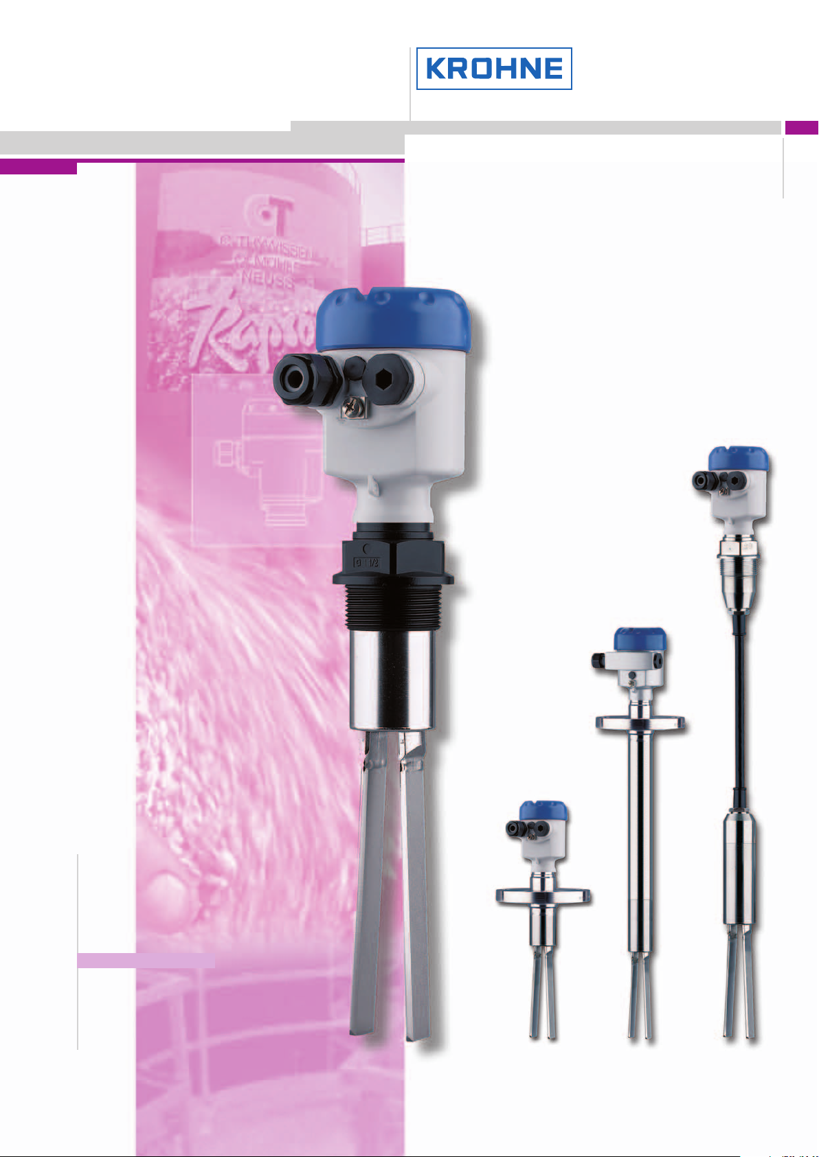
OPTISWITCH 3000 series
Vibration level switch
for solids
●●
Highly robust tuning fork
●●
Insensitive to build-up
●●
Set-up without filling
●●
Detection of solids in water
●●
Maintenance-free
Electromagnetic flowmeters
Variable area flowmeters
Mass flowmeters
Ultrasonic flowmeters
Vortex flowmeters
Flow controllers
Level measuring instruments
Pressure and temperature
Heat metering
Communications technology
Switches, counters, displays and recorders
Engineering systems & solutions
Subject to change without notice.
Page 2

Contents
Contents
1 Description of the measuring principle.................................................. 3
2 Type overview..................................................................... 5
3 Mounting instructions ............................................................... 7
4 Electrical connection
4.1 Preparing the connection .......................................................... 9
4.2 Wiring plan .................................................................... 9
5 Operation
5.1 Adjustment, general ............................................................. 11
5.2 Recurring function test - NAMUR electronics ........................................... 11
5.3 Recurring function test - Two-wire electronics........................................... 11
6 Technical data.................................................................... 13
7 Dimensions ...................................................................... 18
Take note of safety instructions for Ex applications
Please note the Ex specific safety information which you will find on our homepage www.krohne-mar.com and which come
with the appropriate instrument. In hazardous areas you should take note of the appropriate regulations, conformity and type
approval certificates of the sensors and power supply units. The sensors must only be operated on intrinsically safe circuits.
The permissible electrical values are stated in the certificate.
2 Vibration – Level detection of bulk solids
30439-EN-061114
Page 3
Contents
1 Description of the measuring principle
Measuring principle
OPTISWITCH is a level sensor with tuning fork for level detection.
It is designed for industrial use in all areas of process technology
and is preferably used for bulk solids.
The vibrating element (tuning fork) is energized piezoelectrically
and vibrates at its mechanical resonance frequency. The piezos
are fixed mechanically and are hence not subject to temperature
shock limitations. If the vibrating element is submerged in the
product, the vibrating amplitude changes. This change is detected by the integrated oscillator and converted into a switching
command.
Typical applications are overfill and dry run protection. Thanks to
its simple and robust measuring system, OPTISWITCH is virtually unaffected by the chemical and physical properties of the bulk
solid.
It functions even when exposed to strong external vibration or
changing products.
Fault monitoring
The electronics of OPTISWITCH continuously monitors the following criteria:
l Correct vibrating frequency
l Line break to the piezo drive
If one of the stated malfunctions is detected or in case of power
failure, the electronics takes on a defined switchingcondition,e.g.
the relay deenergises (safe condition).
Solid detection in water
With the OPTISWITCH (3100 C, 3200 C, 3300 C) version for solid
detectionin water (option), the vibratingelement is adjusted to the
density of water. If submerged in water (density 1 g/cm³), OPTIS-
WITCH signals "uncovered". Only if the vibrating element is also
covered with solids (e.g. sand, sludge, etc.) will the sensor signal
"covered".
OPTISWITCH 3100 C, 3200 C, 3300 C
OPTISWITCH3100 C, 3200 C and 3300 C level switches are
available in standard, cable and tube version and,
thanks to the
large array of process fittings, offer the optimal solution for any
application. They are completely manufactured of stainless steel
and have all standard approvals.
OPTISWITCH are virtually unaffected by product properties and
must hence not be adjusted.
The level switches can be used in applications with process temperatures up to 250 °C (482 °F) and pressures of up to 16 bar
(232 psi).
You can detect bulk solids up to >0.008 g/cm³ (0.0003 lbs/in³).
OPTISWITCH 3000 C is only available as screwed version with
plastic housing and without approvals.
The most important advantageof this instrument is its price, which
makes the measurement loop very cost-effective.
1.1 Application examples
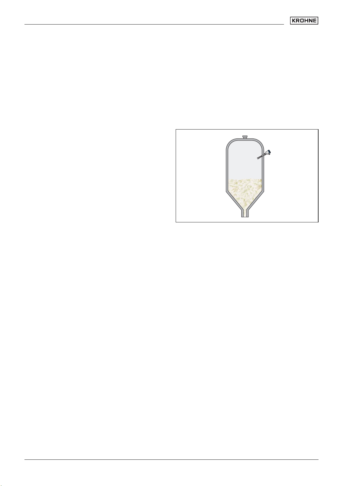
Plastic processing
Fig. 1: Level detection in a silo storing plastic granules
A large number of finished products are produced in the chemical
industry as powder, granules or pellets. Plastic granules and
powder are often stored in high narrow silos which are filled pneumatically.
Vibrating level switches like OPTISWITCH have proven over the
past years in the level detection of plastics. Even with smallest
bulk densities of only 20 g/l and changing products, the instruments deliver always precise results.
Advantages:
l Tuning fork suitable down to a density <20 g/l (e.g. Aerosils)
l Product-independent switching point
l Setup without filling
OPTISWITCH 3000 C
OPTISWITCH 3000 C differs from the OPTISWITCH 3100 C,
3200 C and 3300 C level switches in its simple process fitting of
plastic and the limited selection options. It is suitable for bulk
solids from >0.08 g/cm³ (0.003 lbs/in³).
30439-EN-061114
Vibration – Level detection of bulk solids 3
Page 4
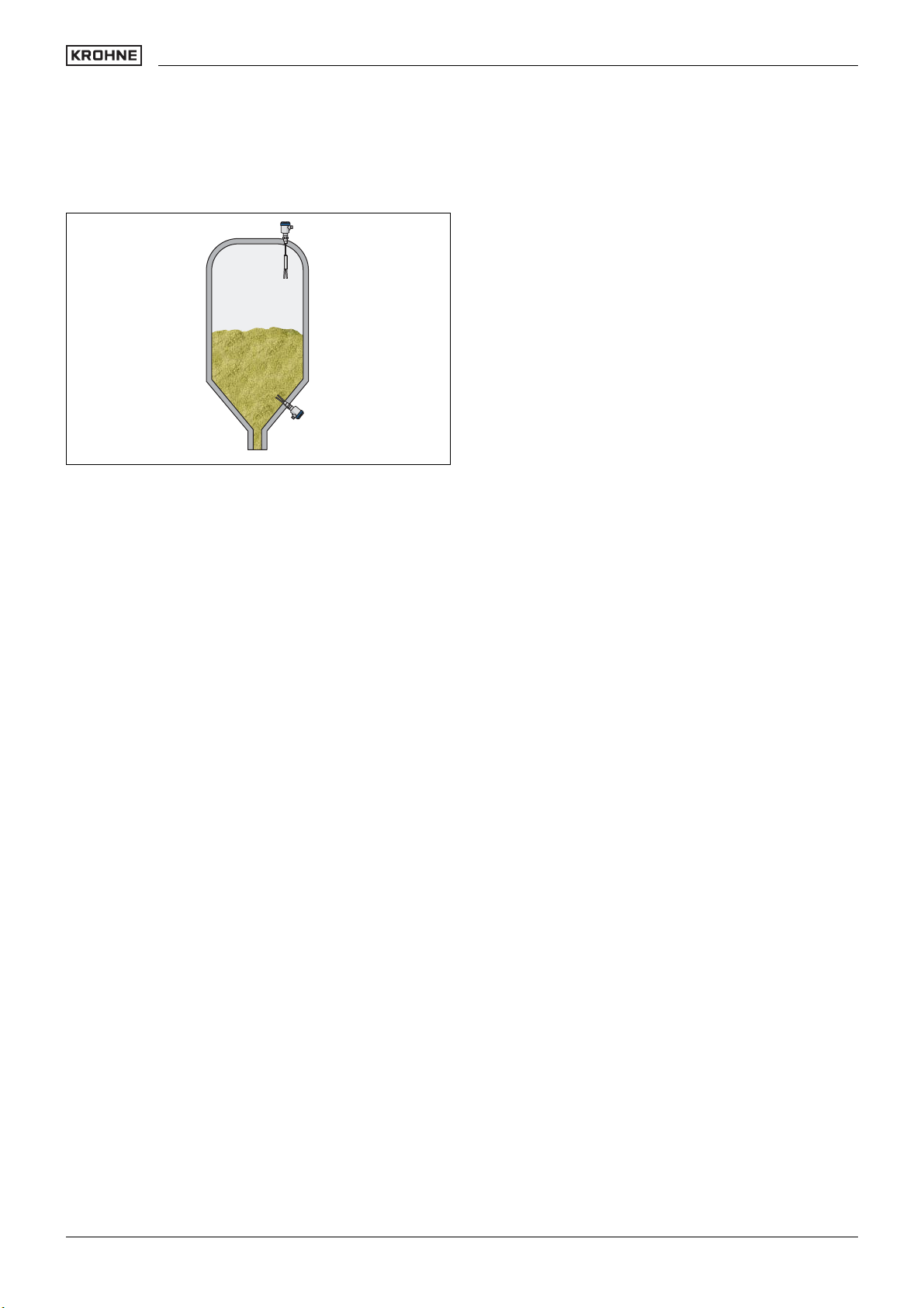
Building material industry
Fig. 2: Silo for aggregatein the building material industry
Description of the measuring principle
Cement or aggregates are placed in interim storage in multiple
chamber silos. When the chambers are filled, large quantities of
dust are generated. Depending on the consistency of the aggregate, different material cones are formed and the product properties can change from filling to filling.
OPTISWITCH offers additional protection against overfilling the
aggregate silo. The flexible suspension cable avoids mechanical
strain caused by movements of the bulk solid. A filling is not
necessary for setup. Because OPTISWITCH has practically no
moving parts, it is not subject to wear.
Advantages:
l very rugged tuning fork
l High abrasion resistance
l insensitive to buildup
l Setup without filling
4 Vibration – Level detection of bulk solids
30439-EN-061114
Page 5
Description of the measuring principle
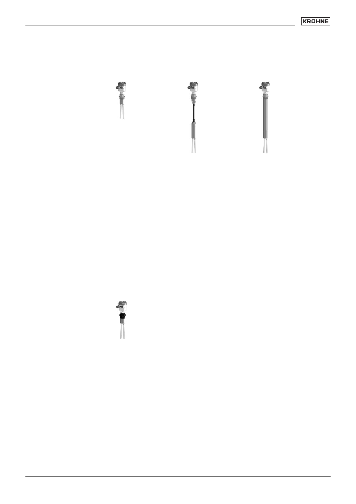
2 Type overview
OPTISWITCH 3100 C OPTISWITCH 3200 C OPTISWITCH 3300 C
Preferred application: Solids Solids Solids
Length:-0.3 … 80 m (1 … 262 ft) 0.3 … 6 m (1 … 20 ft)
Process fitting: Thread G1½A, flanges Thread G1½A, flanges Thread G1½A, flanges
Process temperature:-50 … +150 °C (-58 … +302 °F)
-50 … +250 °C (-58 … +482 °F)
with temperature adapter
Process pressure:-1 … 16 bar/-100 … 1600 kPa
(-14.5 … 232 psi)
Signal output: Relay, transistor, two-wire
output, contactless electronic
switch
Ruggedness ++ ++ ++
Sensitivity ++ ++ ++
Buildup ++ ++ ++
Installation length +++
-20 … +80 °C (-4 … +176 °F)-50 … +150 °C (-58 … +302 °F)
-1 … 6 bar/-100 … 600 kPa
(-14.5 … 87 psi)
Relay, transistor, two-wire
output, contactless electronic
switch
-50 … +250 °C (-58 … +482 °F) with
temperature adapter
-1 … 16 bar/-100 … 1600 kPa
(-
14.5 … 232 psi)
Relay, transistor, two-wire output,
contactless electronic switch
OPTISWITCH 3000 C
Preferred application: Solids
Length:-
Process fitting: Thread G1½A
Process temperature:-50 … +100 °C (-58 … +212 °F)
Process pressure:-1 … 6 bar/-100 … 600 kPa (-14.5 … 232 psi)
Signal output: Relay, transistor, two-wire output, contactless electronic switch
Ruggedness +
Sensitivity -
Buildup ++
Installation length +
30439-EN-061114
Vibration – Level detection of bulk solids 5
Page 6
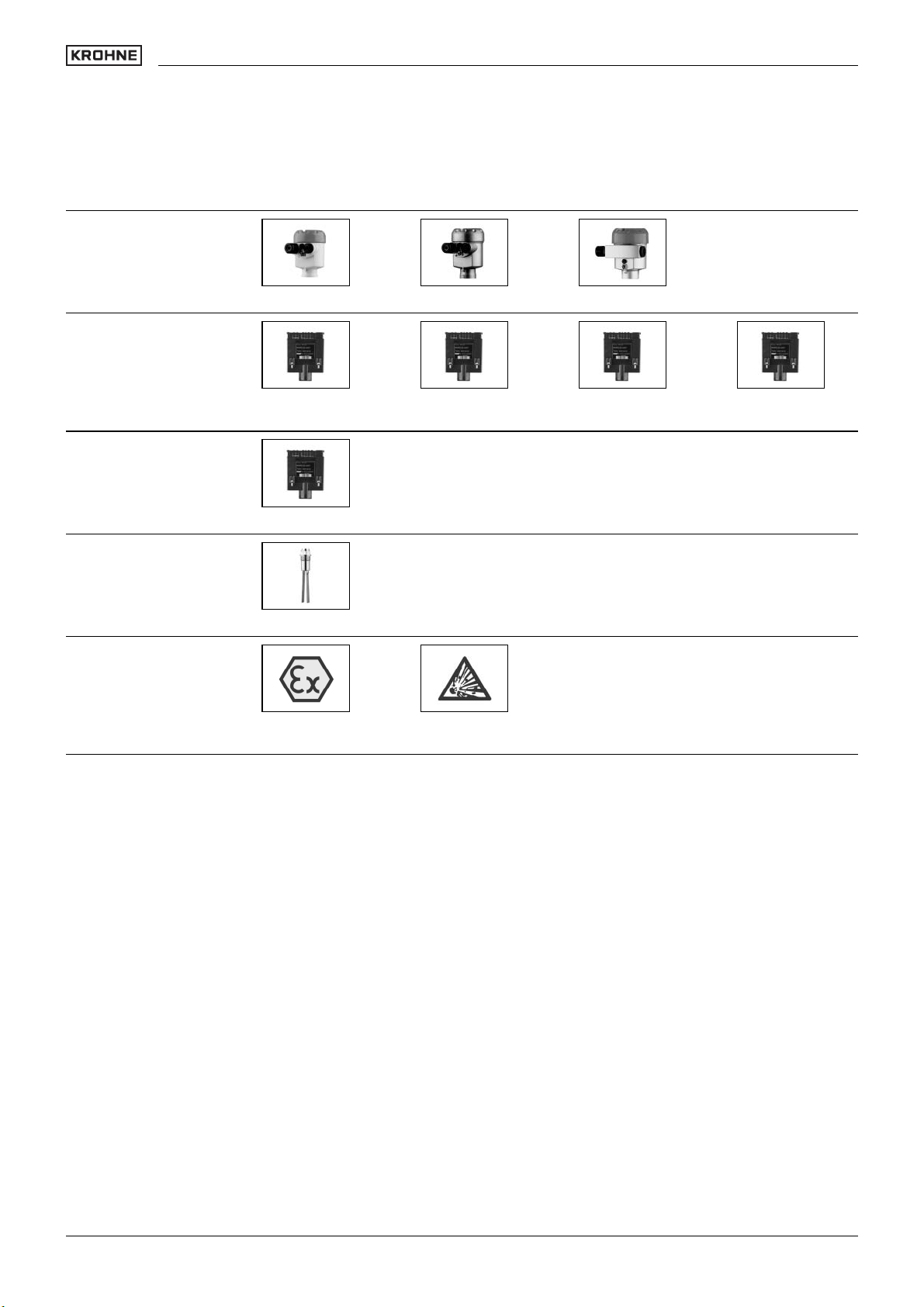
Housing
Electronics
Type overview
Plastic Stainless steel Aluminium
Sensors
Approvals
Relay output Transistor output Contactless elec-
NAMUR output
Tuning fork
Gas explosion pro-
tection
Dust explosion pro-
tection
tronic switch
Two-wire output
6 Vibration – Level detection of bulk solids
30439-EN-061114
Page 7

Type overview
3 Mounting instructions
Switching point
In general, OPTISWITCH can be mounted in any position. The
instrument must be mounted in such a way that the vibrating
element is at the height of the requested switching point.
The only exception is the mounting of the tuning fork vertically
from the bottom. In this position it can happen that product sticks
between the fork tines.
Socket
The vibrating element should protrude into the vessel to avoid
buildup. For that reason, avoid using mounting bosses for flanges
and screwed fittings. This applies particularly for horizontal instal-
lation and with adhesive products.
Filling opening
Install the instrument in such a way that the vibrating element
does not protrude directly into the filling stream. Should such an
installation location be necessary, mount a suitable baffle above
or in front of the vibratingelement, e.g. L80x8 DIN 1028 (see Fig.
Part "a."). In abrasive solids, mounting according to fig. Part "b."
has proven to be a good solution. The mound that forms in the
concave baffle protects it from abrasion.
a.
b.
20°
Fig. 3: Horizontal installation
a. Convex mounting
b. Concave mounting
Inflowing medium
If OPTISWITCH is mounted in the filling stream, unwanted switching signals may be generated. Mount OPTISWITCH at a location
in the vessel where no disturbing influence from e.g. filling openings, agitators etc. can occur.
Fig. 4: Inflowing medium
Horizontal installation
To achieve a very precise switching point, you can install OPTISWITCH horizontally. However, if the switching point can have a
tolerance of a few centimeters, we recommend mounting OPTISWITCH approx. 20° inclined to the vessel bottom to avoid buildup.
Turn the tuning fork of OPTISWITCH 3000 in such a way that no
product is left on the fork surface. To direct the fork, there is a
marking on the hexagon of the thread. Make sure that the marking
points upward.
Material cone
In silos containingsolids, material cones can form which change
the switching point. Please keep this in mind when installing the
sensor in the vessel. We recommend selecting an installation
location where the vibrating element detects an average value
of the material cone.
The vibrating element must be mounted at a location that takes
the arrangement of the filling and emptying apertures into account.
To compensate measurement errors caused by the material cone
in cylindrical vessels, the sensor must be mountedat a distance of
d/6 from the vessel wall.
30439-EN-061114
Vibration – Level detection of bulk solids 7
Page 8

d
6
d d
Fig. 5: Filling and emptying centered
Mounting instructions
This measure applies particularly to applications in Ex
areas. Make sure that the tube is not subjected to bend-
d
6
Should the installation from top be necessary, check if you can
use a cable version.
In the long run, strong vibrations can damage the instrument electronics. With a remote housing these can be disonnected from the
process.
Flows
To minimise flow resistance caused by the tuning fork, OPTISWITCH should be mounted in such a way that the surfaces of the
blades are parallel to the product movement.
ing forces through this measure.
6
d
d
Fig. 6: Filling in the center, emptying laterally
1 OPTISWITCH
2 Emptying opening
3 Filling opening
1
2
3
Tensile load
With cable version, make sure that the max. permissible tensile
load of the suspension cable is not exceeded. T he danger of this
happening exists particularly with very heavy solids and large
meas. lengths. The max. permissible load is stated in chapter
"Technical data".
Agitators
Filling or extraction forces, equipment vibration, or similar, can
subject the level switch to strong lateral forces. For this reason, do
not use an overly long extension tube for OPTISWITCH, but
check if you can mount an OPTISWITCH 3000 C or 3100 C level
switch on the side of the vessel in horizontal position.
Extreme vibration caused by the process or the equipment, e.g.
by fluidization or beaters in the vessel, can cause the extension
tube of OPTISWITCH to vibrate in resonance. This leads to increased stress on the upper weld joint. Should a longer tube
version be necessary, you can provide a suitable support or
guy directly above the vibrating element to secure the extension
tube.
1
2
Fig. 7: Orientation of the tuning fork in case of flow
1 Marking with screwed version
2 Direction of flow
Lock fitting
OPTISWITCH in tube version can be mounted with a lock fitting
for height adjustment. Take note of the pressure specifications of
the lock fitting.
Baffle protection against falling rocks
In applications such as grit chambers or settling basins for coarse
sediments, the vibrating element must be protected against damage with a suitable baffle.
> 125 mm
59
(4
/64")
Fig. 8: Baffle protection against damages
Pressure/Vacuum
The process fitting must be sealed if there is gauge or low pressure in the vessel. Check if the seal material is resistant against
the measured product and the process temperature.
30439-EN-061114
8 Vibration – Level detection of bulk solids
Page 9

Mounting instructions
4 Electrical connection
4.1 Preparing the connection
Note safety instructions
Generally note the following safety instructions:
l Connect only in the complete absence of line voltage
Take note of safety instructions for Ex applications
In hazardous areas you should take note of the appropriate regulations, conformity and type approval certifi-
cates of the sensors and power supply units.
Select power supply
Connect the power supply according to the following diagrams.
Oscillators with relay output and contactless electronic switch are
designed in protection class 1. To maintain this protection class, it
is absolutely necessary that the ground conductor be connected
to the internal ground terminal. Take note of the general installation regulations. As a rule, connect OPTISWITCH to vessel
ground (PA), or in case of plastic vessels, to the next ground
potential. On the side of the housing there is a ground terminal
between the cable entries. This connection serves to drain off
electrostatic charges. In Ex applications, the installation regulations for hazardous areas must be given priority.
The data for power supply are stated in the "Technical data" in the
"Supplement".
Selecting connection cable
The instrument is connected with standard cable with round cross
section. An outer cable diameter of 5 ... 9 mm (0.2 ... 0.35 in)
ensures the seal effect of the cable gland
If cable with a different diameter or wire cross section is used,
exchange the seal or use an appropriate cable connection.
.
3
2 1
Fig. 9: Wiring plan, single chamber housing
1 Relay output
2 Relay output
3 Voltage supply
Transistor output
We recommend connecting OPTISWITCH in such a way that the
switching circuit is open when there is a level signal, line break or
failure (safe condition).
The instrument is used to control relays, contactors, magnet
valves, warning lights, horns as well as PLC inputs.
In hazardous areas, only use approved cable connections for OPTISWITCH.
Select connection cable for Ex applications
Take note of the corresponding installation regulations
for Ex applications.
4.2 Wiring plan
Relay output
We recommend connecting OPTISWITCH in such a way that the
switching circuit is open when there is a level signal, line break or
failure (safe condition).
The relays are always shown in non-operative condition.
30439-EN-061114
1
Fig. 10: Wiring plan, single chamber housing
+-
+ -
Fig. 11: NPN action
Vibration – Level detection of bulk solids 9
Page 10

Electrical connection
+-
+ -
Fig. 12: PNP action
Contactless electronic switch
We recommend connecting OPTISWITCH in such a way that the
switching circuit is open when there is a level signal, line break or
failure (safe condition).
The contactless electronic switch is always shown in non-operative condition.
The instrument is used for direct control of relays, contactors,
magnet valves, warning lights, horns etc. It must not be operated
without an intermediately connected load, because the electronics would be destroyed if connected directly to the mains. It
is not suitable for connection to low voltage PLC inputs.
Domestic current is temporarily lowered below 1 mA after switching off the load so that contactors, whose holding current is lower
than the constantdomestic current of the electronics, are reliably
switched off.
When OPTISWITCH is used as part of an overfill protection system according to WHG, also note the regulations of the general
type approval.
Take note of the operating instructions manual of the signal conditioning instrument. Suitable signal conditioning instruments are
listed in chapter "Technical data".
1
Fig. 14: Wiring plan, single chamber housing
1 Voltage supply
NAMUR output
For connection to an amplifier according to NAMUR (IEC
60947-5-6,EN 50227). For further information see chapter "Tech-
nical data".
++-
1 2
-
Fig. 15: Wiring plan, single chamber housing
1
Fig. 13: Wiring plan, single chamber housing
1 Screening
Two-wire output
We recommend connecting OPTISWITCH in such a way that the
switching circuit is open when there is a level signal, line break or
failure (safe condition).
For connection to an SU 501 signal conditioning instrument dto.
Ex. The sensor is powered by the connected signal conditioning
instrument. Further informationis available in chapter "Technical
data" in the "Supplement", "Ex-technical data" are available in the
supplied "Safety information manual".
10 Vibration – Level detection of bulk solids
30439-EN-061114
Page 11

5 Operation
Electrical connection
5.1 Adjustment, general
1
5
2
4
3
Fig. 16: Adjustment elements electronics module, e.g. relay output (VB60R)
1 Potentiometer for switching point adaptation (not with OPTISWITCH 3000 C)
2 DIL switch for mode adjustment
3 Ground terminal
4 Screwed terminals
5 Control lamp
Switching point adaptation (1)
OPTISWITCH 3100 C, 3200 C, 3300 C
You can adapt the switching point of OPTISWITCH to the solid
with the potentiometer. The switching point is preset and covered
by a label. It must only be modified in special cases.
OPTISWITCHs with tuningfork are preset to a product density of
>0.02 g/cm³ (0.0007 lbs/ in³). In very light solids, turn the potenti-
ometer to complete left position 0.008 … 0.1 g/cm³)
(0.0003 … 0.0036 lbs/in³). By doing this, the tuning fork will be
more sensitive and can detect very light solids, such as e.g. Aerosils more reliably.
OPTISWITCH 3000 C
OPTISWITCH 3000 C can detect bulk solids from a product density of >0.08 g/cm³ (0.003 lbs/in³).
Mode adjustment (2)
With the mode adjustment (min./max.) you can change the
switching condition of the output. You can set the required mode
(max.-max. detection or overfill protection, min.-min. detection
or dry run protection).
Signal lamp (5)
Diode for indication of the switching status.
5.2 Recurring function test - NAMUR elec-
tronics
According to IEC 61508.
SIL
OPTISWITCH is qualified in mode A (overfill protection) for use in
measuring chains of stage SIL2 according to IEC 61508 (redundant, stage SIL3).
You find the "Safety Manual" with detailed specification on SIL on
our website.
Recurring function test
The recurring test according to IEC 61508 can be carried out by
pushing the simulation key on the oscillator or by briefly (>2 sec-
onds) interrupting the supply to the sensor. The correct sequence
of the switching conditions must be monitored via the switching
amplifier as well as the connected systems. The sensor must
neither be removednor a response triggered by filling the vessel.
You can carry out the function test with the outputted current
values also directly via a safety PLC or a process controlsystem.
Simulation key on the electronics module
OPTISWITCH has an integrated simulation key. The simulation
key is lowered on the electronics module. Push the simulation key
for >2 seconds
.
If OPTISWITCH is connected to an SPLC, you have to interrupt
the connection cable to the sensor for >2 seconds.
After releasing the simulation key or briefly interrupting the connection cable to the sensor, you can check the complete measuring system on correct function. A switching procedure is simulated during the test.
I/mA
2,2
1
3 4,5 t/s
Fig. 17: Flow chart of the function test
1 Full signal
2 Empty signal
1
2
Check if all the switching conditions occur in the correct sequence
and the stated time period. If this is not the case, there is a fault in
the measuring system. Keep in mind that connected instruments
are activated during the function test. This allows you to check the
correct function of the measuring system.
5.3 Recurring function test - Two-wire elec-
tronics
According to IEC 61508.
SIL
OPTISWITCH in conjunction with a suitable signal conditioning
instruments is qualified in mode A (overfill protection) for use in
measuring chains of stage SIL2 according to IEC 61508 (redundant, stage SIL3).
You find the "Safety Manual" with detailed specification on SIL on
our website.
Recurring function test
The recurring test according to IEC 61508 can be carried out by
pushing the test key on the signal conditioning instrument or by
briefly (>2 seconds) interrupting the supply to the sensor. The
correct sequence of the switching conditions must be monitored
via the two LEDs on the signal conditioninginstrument as well as
the connected systems. The sensor must neither be removed nor
a response triggered by filling the vessel.
30439-EN-061114
Vibration – Level detection of bulk solids 11
Page 12

Operation
You can carry out the function test with the outputted current
values also directly via a safety PLC or a process controlsystem.
The implementation and switching sequence of the function test
is described also in the operating instructions manual of the appropriate signal conditioning instrument.
Test key on the signal conditioning instrument
The signal conditioning instrument has an integrated test key. The
test key is lowered in the front plate of the signal conditioning
instrument. Push the test key with a suitable object (e.g. screwdriver, pen etc.) for >2 seconds.
If OPTISWITCH is connected to an SPLC, you have to interrupt
the connection cable to the sensor for >2 seconds.
After releasing the test key or interrupting the connection cable to
the sensor, the complete measuring system can be checked on
correct function. The following operating conditions are simulated
during the test:
l Fault signal
l Empty signal
l Full signal
I/mA
16
8
2
1,5 3 4,5 t/s
Fig. 18: Flow chart of the function test
1 Full signal
2 Empty signal
1
2
Check if all the switching conditions occur in the correct sequence
and the stated time period. If this is not the case, there is a fault in
the measuring system. Keep in mind that connected instruments
are activated during the function test. This allows you to check the
correct function of the measuring system.
12 Vibration – Level detection of bulk solids
30439-EN-061114
Page 13

Operation
6 Technical data
General data
Material 316L corresponds to 1.4404 or 1.4435
OPTISWITCH 3000 C
Materials, wetted parts
- Process fitting - thread PBT
- vibrating element 316L/318S13 (1.4462)
Materials, non-wetted parts
- Housing plastic PBT (Polyester)
- Seal ring between housing and housing cover Silicone
- Ground terminal 316Ti/316L
Weight 1150 g (40 oz)
Max. lateral load 600 N (135 lbf)
OPTISWITCH 3100 C
Materials, wetted parts
- Process fitting - thread 316
- Process fitting - flange 316L
- Seal Klingersil C-4400
- vibrating element 316L
- Extension tube (OPTISWITCH 3300 C) ø 43 mm (1.7 in) 316L
Materials, non-wetted parts
- Housing Plastic PBT (Polyester), Alu die-casting powder-coated, 316L
- Seal ring between housing and housing cover NBR (stainless steel housing), silicone (Alu/plastic housing)
- Ground terminal 316Ti/316L
Weights
- OPTISWITCH 3100 C with plastic housing 1500 g (53
- OPTISWITCH 3100 C with Aluminium housing 1950 g (69 oz)
- OPTISWITCH 3100 C with stainless steel housing 2300 g (81 oz)
Max. lateral load 600 N (135 lbf)
OPTISWITCH 3200 C
Materials, wetted parts
- Process fitting - thread 316L
- Process fitting - flange 316L
- Seal CR, CSM
- vibrating element 316L
- Suspension cable PUR
Materials, non-wetted parts
- Housing Plastic PBT (Polyester), Alu die-casting powder-coated, 316L
- Seal ring between housing and housing cover NBR (stainless steel housing), silicone (Alu/plastic housing)
- Ground terminal 316Ti/316L
Weights
- OPTISWITCH 3200 C with plastic housing 1500 g (53 oz)
- OPTISWITCH 3200 C with Aluminium housing 1950 g (69 oz)
- OPTISWITCH 3200 C with stainless steel 2300 g (81 oz)
- Suspension cable approx. 165 g/m (1.8 oz/ft)
Max. permissible tensile load 3000 N (675 lbs)
Sensor length 0,3 … 80 m (1 … 262 ft)
OPTISWITCH
Materials, wetted parts
- Process fitting - thread 316L
- Process fitting - flange 316L
- Seal Klingersil C-4400
- vibrating element 316L
- Extension tube (OPTISWITCH 3300 C) ø 43 mm (1.7 in) 316L
Materials, non-wetted parts
- Housing Plastic PBT (Polyester), Alu die-casting powder-coated, 316L
- Seal ring between housing and housing cover NBR (stainless steel housing), silicone (Alu/plastic housing)
- Ground terminal 316Ti
3300 C
L
oz)
/316L
30439-EN-061114
Vibration – Level detection of bulk solids 13
Page 14

Technical data
Weights
- OPTISWITCH 3300 C with plastic housing 1500 g (53 oz)
- OPTISWITCH 3300 C with Aluminium housing 1950 g (69 oz)
- OPTISWITCH 3300 C with stainless steel housing 2300 g (81 oz)
- Extension tube (OPTISWITCH 3300 C) ø 43 mm (1.7 in) approx. 2000 g/m (21.5 oz/ft)
Sensor length 0.3 … 6 m (1 … 20 ft)
Max. lateral load 290 Nm (214 lbf ft), max. 600 N (135 lbf)
Max. lateral load
- OPTISWITCH 3300 C 290 Nm (214 lbf ft), max. 600 N (135 lbf)
Output variable
Relay output
Output relay output (DPDT), 2 floating spdts
Turn-on voltage
- min. 10 mV
- max. 253 VAC, 253 VDC
Switching current
- min. 10 µA
- max. 5 AAC, 1 ADC
Breaking capacity
- max. 1250 VA, 50 W
Contact material (relay contacts) AgCdO and Au plated
Modes (adjustable) min./max.
Delay time
- when immersed approx. 0.5 s
- when laid bare approx. 1 s
Transistor output
Output floating transistor output, overload and permanently shortcircuit proof
Load current max.
Turn-on voltage max. 55 VDC
Blocking current <100 µA
Modes (adjustable) min./max.
Delay time
- when immersed approx. 0.5 s
- when laid bare approx. 1 s
Contactless electronic switch
Output Contactless electronic switch
Modes (adjustable) min./max.
Delay time
- when immersed approx. 0.5 s
- when laid bare approx. 1 s
Two-wire output
Output Two-wire output
Suitable signal conditioning instruments SU 501
Output signal
- Mode min. Vibrating element uncovered: 16 mA ±1 mA, vibrating element covered:
- Mode max. Vibrating element uncovered: 8 mA ±1 mA, vibrating element covered:
- Fault signal <2 mA
Modes (adjustable) min./max.
Delay time
- when immersed approx. 0.5 s
- when laid bare approx. 1 s
NAMUR output
Output Two-wire NAMUR output
400 mA
8 mA ±1 mA
16 mA ±1 mA
30439-EN-061114
14 Vibration – Level detection of bulk solids
Page 15

Technical data
Current consumption
- Falling characteristics (max.) ≥2.2 mA uncovered/≤1 mA covered
- Rising characteristics (min.) ≤1 mA uncovered/≥2.2 mA covered
- Fault signal ≤1 mA
Necessary processing system NAMUR processing system according to IEC 60947-5-6 (EN 50227/
Modes (NAMUR output adjustable to falling or rising characteristics)
- min. rising characteristics (High current when immersed)
- max. falling characteristics (Low current when immersed)
Ambient conditions
Ambient temperature on the housing -40 … +70 °C (-40 … +158 °F)
Storage and transport temperature -40 … +80 °C (-40 … +176 °F)
Process conditions
OPTISWITCH 3000 C
Parameter Limit level of solids
Process pressure -1 … 6 bar/-100 … 600 kPa (-14.5 … 87 psi) with PN 40
Process temperature OPTISWITCH of 316L -50 … 100 °C (-58 … +212 °F)
Density >0.08 g/cm³ (0.003 lbs/in³)
Granular size ø max. 15 mm (0.6 in)
OPTISWITCH 3100 C, 3300 C
Parameter Limit level of solids
Process pressure -1 … 25 bar
Process temperature OPTISWITCH of 316L -50 … 150 °C (-58 … 302 °F)
Process temperature (thread or flange temperature) with tem-
perature adapter (option)
DIN 19234)
/-100 … 2500 kPa (-14.5 … 363 psi) with PN 40
-50 … 250 °C (-58 … 482 °F)
(176˚F)
(104˚F)
(32˚F)
-50˚C
(-58˚F)
-40˚C
(-40˚F)
Fig. 19: Ambient temperature - Product temperature
1 Product temperature
2 Ambient temperature
3 Temperature range with temperature adapter
Density >0.008 g/cm³ (0.0003 lbs/in³)
Granular size ø max. 15 mm (0.6 in)
OPTISWITCH 3200 C
Parameter Limit level of solids
Process pressure -1 … 6 bar/-100 … 600 kPa (-14.5 … 87 psi) with PN 40
Process temperature OPTISWITCH of 316L -20 … +80 °C (-4 … +176 °F)
Density >0.008 g/cm³ (0.0003 lbs/
Granular size ø max. 15 mm (0.6 in)
Electromechanical data
Cable entry/plug (dependent on the version)
- Single chamber housing
30439-EN-061114
2
80˚C
40˚C
0˚C
50˚C
(122˚F)
100˚C
(212˚F)
150˚C
(302˚F)
3
200˚C
(392˚F)
250˚C
(482˚F)
1
in³)
l 1x cable entry M20x1.5 (cable-ø 5 … 9 mm), 1x blind stopper
M20x1.5; attached 1x cable entry M20x1.5
Vibration – Level detection of bulk solids 15
Page 16

Technical data
or:
l 1x cable entry ½ NPT, 1x blind stopper ½ NPT, 1x cable entry ½ NPT
or:
l 1xplugM12x1, 1x blind stopper M20x1.5
Spring-loaded terminals for wire cross-section up to 1.5 mm²
Adjustment elements
Electronics versions - relay, transistor output, contactless electronic switch
Mode switch
- min. Min. detection or dry run protection
- max. Max. detection or overfill protection
Electronics version - two-wire output
Mode switch
- min. Vibrating element uncovered: 16 mA ±1 mAVibrating element uncovered:
- max. Vibrating element uncovered: 8 mA ±1 mAVibrating element covered:
Electronics version - NAMUR output
Mode switch
- min. rising characteristics (High current when immersed)
- max. falling characteristics (Low current when immersed)
8 mA ±1 mA
16 mA ±1 mA
Voltage supply
Relay output
Supply voltage 20 … 253 VAC, 50/60 Hz, 20 … 72 VDC(at U >60 VDC, the ambient
Power consumption 1 … 8 VA (AC), approx. 1.3 W (DC)
Transistor output
Supply voltage 10 … 55 VDC
Power consumption max. 0.5 W
Contactless electronic switch
Supply voltage 20 … 253 VAC, 50/60 Hz, 20 … 253 VDC
Domestic current requirement approx. 3 mA (via load circuit)
Load current
-
min. 10 mA
- max. 400 mA (at I >300 mA the ambient temperature can be max. 60 °C/140 °F)
Two-wire output
Supply voltage 10 … 36 VDC(via the signal conditioning instrument)
NAMUR output
Supply voltage (standard characteristics) for connection to amplifier according to NAMUR IEC 60947-5-6, approx.
Open-circuit voltage U
Shortcircuit current I
temperature can be max. 50 °C/122 °F)
max. 4 A up to 40 ms
8.2 V
approx. 8.2 V
0
approx. 8.2 mA
U
Electrical protective measures
Electronics versions - relay output, contactless electronic switch
Protection IP 66/IP 67
Overvoltage category III
Protection class I
Electronics versions - Transistor, two-wire, NAMUR output
Protection IP 66/IP 67
Overvoltage category III
16 Vibration – Level detection of bulk solids
30439-EN-061114
Page 17

Technical data
Protection class II
Approvals
OPTISWITCH 3000 C
OPTISWITCH 3000 C has no approvals.
OPTISWITCH 3100 C, 3200 C, 3300 C, electronics versions - relay output, transistor output, contactless electronic switch
ATEX II 1/2G, 2GEExdIIC T6
ATEX II 1/2 DIP66 T
OPTISWITCH 3100 C, 3200 C, 3300 C, electronics version - two-wire output
ATEX II 1G, 1/2G, 2GEExiaIIC T6
ATEX II 1G, 1/2G, 2GEExiaIIC T6 + ATEX II 1/2 DIP66 T6
ATEX II 1/2G,
ATEX II 1/2 DIP66 T
CE conformity
2GEExdIIC T6
Electronics versions - Relay, transistor, two-wire, NAMUR output
EMVG (89/336/EWG), Emission: EN 61326: 1997 (class B),
Susceptibility: EN 61326: 1997/A1: 1998
NSR (73/23/EWG), EN 61010-1: 2001
Electronics version - contactless electronic switch
EMVG (89/336/EWG), Emission: EN 61326/A1: 1998 (class B),
Susceptibility: EN 61326: 1997/A1: 1998
NSR (73/
23/EWG), EN 61010-1: 2001
SIL conformity
OPTISWITCH fulfills the requirements of functional safety according to IEC 61508. You can find further information in the
"Safety Manual OPTISWITCH".
30439-EN-061114
Vibration – Level detection of bulk solids 17
Page 18

7 Dimensions
/
/
/
M20x1,5
½
/
½
/
½
3
Technical data
Housing
M20x1,5
~ 116mm
9
(4
ø 84mm
(3
/16")
5
/16")
~ 69mm
23
(2
/32")
ø 77mm
1
(3
/32")
~ 69mm
23
(2
/32")
ø 77mm
1
(3
/32")
2
4
M20x1,5
4
4
Fig. 20: Housing versions (OPTISWITCH 3000 C only with plastic housing)
1 Plastic housing
2 Stainless steel housing
3 Aluminium housing
OPTISWITCH 3000 C
")
64
/
13
30,4mm
")
64
/
55
22mm
(
")
16
/
11
")
32
/
220,5mm (8
29
(1
G1½A
ø 43mm (1 11/16")
OPTISWITCH 3200 C
4
1
4
")
64
/
55
22mm
(
L
")
64
/
19
160mm (6
")
32
/
29
150mm (5
G1½A
ø 43mm (1 11/16")
ø 11mm (7/16")
ø 43mm (1
33mm
")
64
/
19
(1
11
/16")
150mm (5
Fig. 21: OPTISWITCH 3000 C, threaded version G1½
OPTISWITCH 3100 C
")
64
/
19
33mm
")
64
/
55
22mm
(
")
32
/
21
220mm (8
")
32
/
29
150mm (5
Fig. 22: OPTISWITCH 3100 C, Screwed version G1½
(1
G1½A
ø 43mm (1 11/16")
Fig. 23: OPTISWITCH 3200 C, Screwed version G1½
30439-EN-061114
18 Vibration – Level detection of bulk solids
Page 19

OPTISWITCH 3300 C
")
64
/
55
22mm
(
L
")
32
/
29
")
64
/
19
33mm
(1
G1½A
ø 43mm (1 11/16")
150mm (5
Fig. 24: OPTISWITCH 3300 C, threaded version G1½
Temperature adapter
")
64
/
1
178 mm (7
Fig. 25: Temperature adapter (only for OPTISWITCH 3100 C and 3200 C)
ø 34 mm
11
(1
/32")
30439-EN-061114
Vibration – Level detection of bulk solids 19
 Loading...