

Page 1
Technical Data Sheet
KROHNE 01/2006 7.02544.22.00
©
CMD
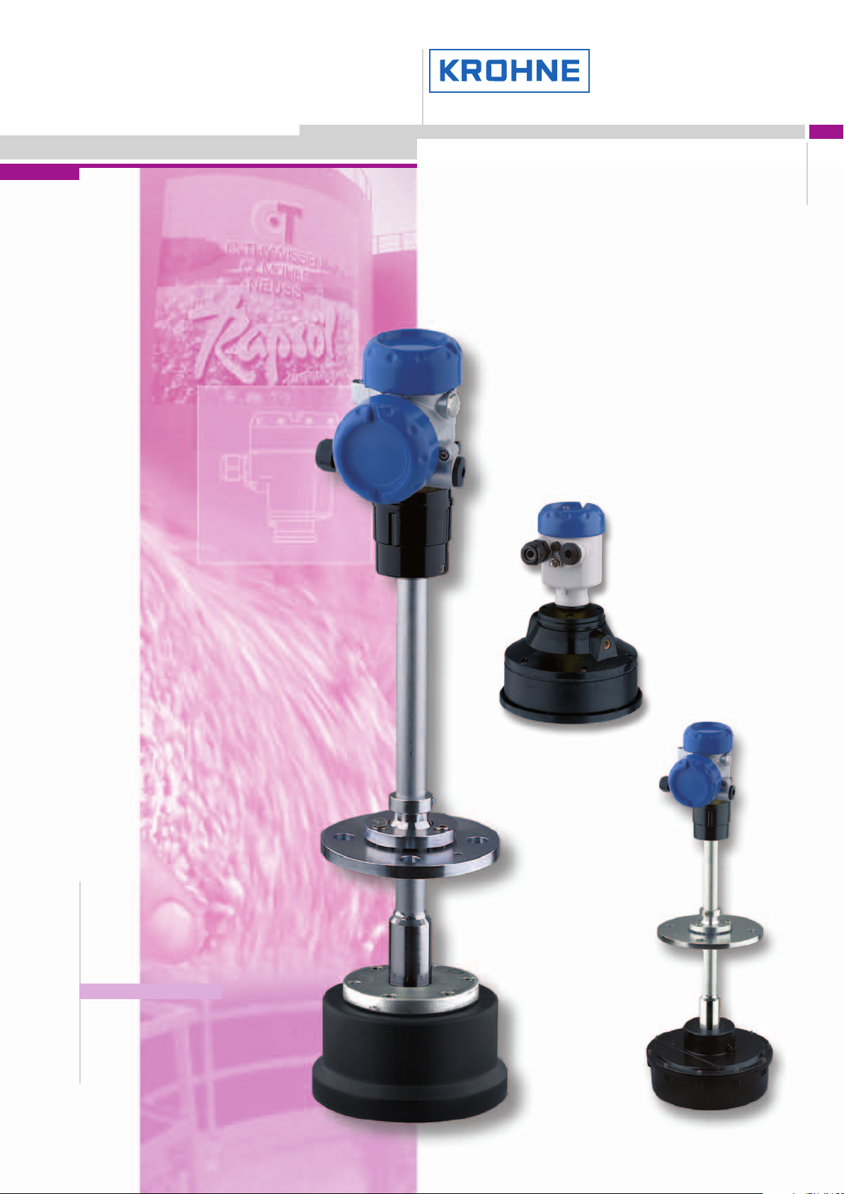
OPTISOUND 3030C-3050C
Ultrasonic Level Gauge
for solids
●●
Level measurement during processing and
storage of solids
●●
Level indication of solids in silos and hoppers
●●
Level measurement in stone crushes
●●
Profile measurement on conveyor belts
Electromagnetic flowmeters
Variable area flowmeters
Mass flowmeters
Ultrasonic flowmeters
Vortex flowmeters
Flow controllers
Level measuring instruments
Pressure and temperature
Heat metering
Communications technology
Switches, counters, displays and recorders
Engineering systems & solutions
Subject to change without notice.
Page 2

Contents
Contents
1 Description of the measuring principle......................... 3
2 Type overview............................................ 6
3 Mounting information ...................................... 8
4 Electrical connection
4.1 General requirements ................................... 14
4.2 Supply voltage ........................................ 14
4.3 Connection cable ...................................... 14
4.4 Connection of the cable screen and grounding................. 14
4.5 Wiring plans OPTISOUND 3030 C ......................... 15
4.6 Wiring plans OPTISOUND 3040 C and 3050 C ................ 16
5 Adjustment
5.1 Adjustment, general .................................... 17
5.2 Compatibility acc. to NAMUR NE 53 ........................ 17
5.3 Adjustment with the indicating/adjustment module .............. 18
6 Technical data........................................... 19
7 Dimensions ............................................. 27
Take note of safety
instructions for Ex
application
Please note the Exspecific safety information which you will find on our homepage
www.krohne-mar.comand which come with the appropriate instrument. In hazardous
areas you should take note of the appropriate regulations, conformity and type approval certificates of the sensors and power supply units. The sensors must only be
operated on intrinsically safe circuits. The permissible electrical values are stated in
the certificate.
2 Ultrasonic – Level measurement in solids
30601-EN-050816
Page 3

Description of the measuring principle
1 Description of the measuring principle
Measuring principle
Short ultrasonic pulses in the range of 18 kHzto35 kHz are emittedby the transducer
to the product surface, reflected there and received by the transducer. The pulses
travel at the speed of sound - the elapsed time from emission to reception of the
signals depends on the level in the vessel.
The latest microcomputer technology and the proven processing software select the
level echofrom among any number offalse echoes andcalculate the exact distance to
the product surface. An integratedtemperature sensor detects the temperature in the
vessel and compensates the influence of temperature on the signal running time.
By simply entering the vessel dimensions, a level-proportional signal is generated
from the distance. It is not necessary to fill the vessel for adjustment.
Wide application range
OPTISOUND 3030 C, 3040 C and 3050 C ultrasonic sensors are especially suitable
for level measurement of solids, but are also good for liquids. The instrumentsdiffer in
the measuring range, the transducer version and the process fitting. Through diffe-
rent, adapted emitting frequencies and efficient transducers, levels in a measuring
range of 15 … 45 m (49.2 … 147.6 ft
transducers and process fittings also allow applications in corrosive products (depending on the model).
) can be measured. Resistant materials for the
A version suitable for each application
Adaptable sensors are a must for the wide variety of product characteristics and
installation conditions. OPTISOUND ultrasonic sensors meet this requirement with
versions suitable for all applications.
A practical mounting strap (option) enables flexible orientation of OPTISOUND 3030
C.
Four different versions of OPTISOUND 3040 C and 3050 C enable installation in
virtually all vessels and optimum orientation to the product cone:
l Version A compact in flange version
l Version B compact with swivelling holder
l Version C separate with swivelling holder
l Version D separate with thread fitting.
Unaffected by product properties
Fluctuations in product composition or even complete product changes do not influ-
ence the measuring result. A fresh adjustment is not necessary.
Service and maintenance friendly
Thanks to the non-contact measuringprinciple, OPTISOUND sensors are particularly
easy to service and maintain.
30601-EN-050816
Ultrasonic – Level measurement in solids 3
Page 4
Description of the measuring principle
1.1 Application examples
Conveyor belt with sugar beets
Fig. 1: Profile measurement on a conveyor belt withOPTISOUND 3030
C
The sugarbeets used for sugar production arepoured from trucksonto conveyor belts
on which they are transported for further processing. OPTISOUND sensors are an
economic solution for profile monitoring. Ultrasonic waves are reflected by the medium, the integrated electronics detects the charging height of the conveyor belt. By
means of the mounting strap, OPTISOUND 3030 C can be optimally oriented to the
medium. Thanks to its high emitting power, fog, wind and moisture do not affect
measurement reliability.
4 Ultrasonic – Level measurement in solids
30601-EN-050816
Page 5
Description of the measuring principle
Plastic granules
Fig. 2: Level measurement in a plastic granules silo with OPTISOUND
3040 C
Plastic granules are often stored in high, narrow silos that are filled pneumatically.
OPTISOUND ultrasonic sensors are particularly suitable for level measurement of
plastic granules. They are equipped with powerful transducers and optimised signal
processing. A swivelling holder on the mounting flange ensures optimum orientation
to the product, also when material cones form.
30601-EN-050816
Ultrasonic – Level measurement in solids 5
Page 6
Type overview
2 Type overview
OPTISOUND 3030 C OPTISOUND 3040 C
Preferred application: liquids and solids Solids
Measuring range: liquids: 0.6 … 15 m (2 … 49.2 ft)
solids: 0.6 … 7 m (2 … 23 ft)
Process fitting: compression flange DN 100 or mounting
strap
Process temperature:-40 … +80°C (-40 …
Process pressure:-20 … 100 kPa
(-0.2 … 1.0 bar/-2.9 … 14.5 psi)
Signal output two-wire/four-wire 4 … 20 mA/HART four-wire 4 … 20 mA/HART
OPTISOUND 3050 C
Preferred application: Solids
+176°F)-40 … +80°C (-40 … +176°F)
liquids: 1 … 25 m (3.3 … 82 ft)
solids: 1 … 15 m (3.3 … 49.2 ft)
flange DN 200, with swivelling holder from
DN 50
-20 … 150 kPa
(-0.2 … 1.5 bar/-2.9 … 21.8 psi)
Measuring range: liquids: 0.8 … 45 m (2.6 … 147.6 ft)
solids: 0.8 … 25 m (2.6 … 82 ft)
Process fitting: flange DN 250, with swivelling holder
from DN 50
Process temperature:-40 … +80°C (-40 … +176°F)
Process pressure:-20 … 150 kPa
(-0.2 … 1.5 bar/-2.9 … 21.8 psi)
Signal output four-wire 4 … 20 mA/HART
6 Ultrasonic – Level measurement in solids
30601-EN-050816
Page 7
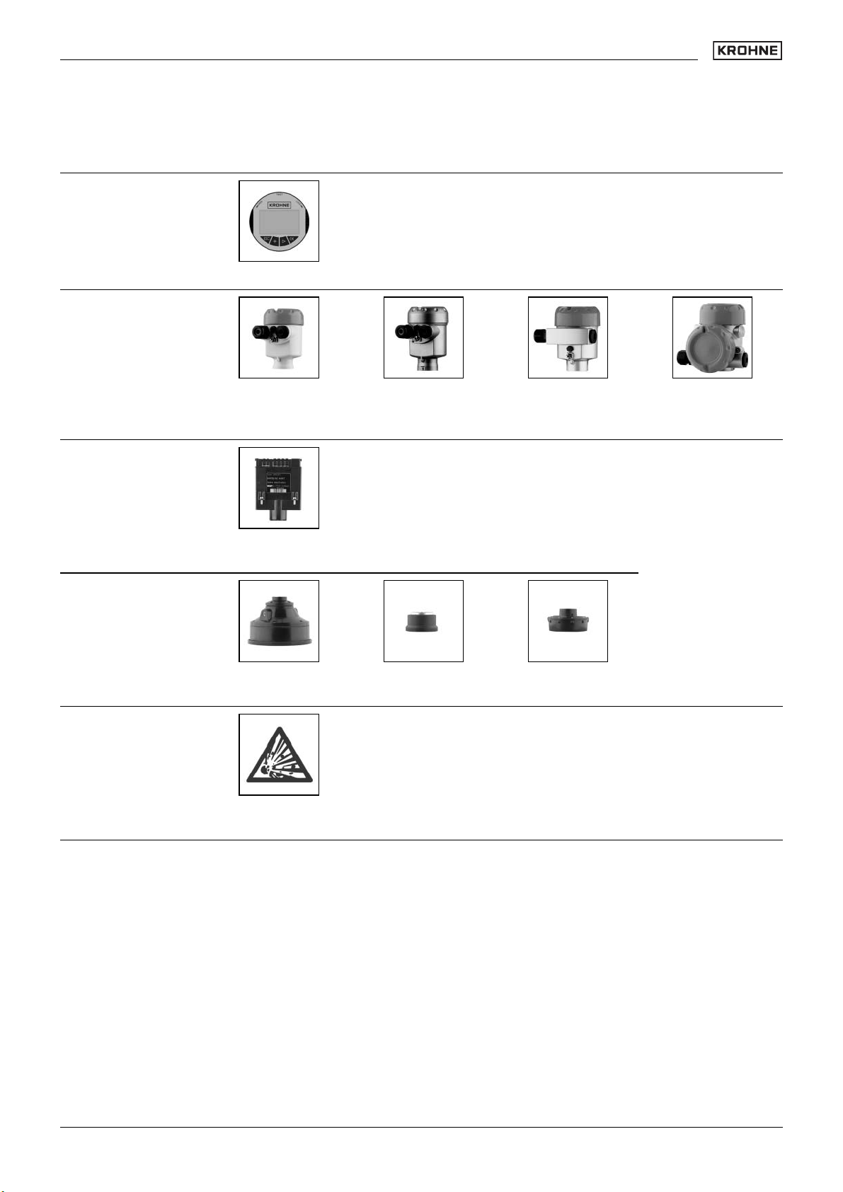
Indicating and
adjustment module
Housing
Electronics
Type overview
Plastic Stainless steel Aluminium Aluminium
(double cham-
ber)
Sensors
Approvals
4 … 20 mA/
HART four-wire
Transducer
15 m
Dust explosion
protection
Transducer
25 m
Transducer
45 m
30601-EN-050816
Ultrasonic – Level measurement in solids 7
Page 8
Mounting information
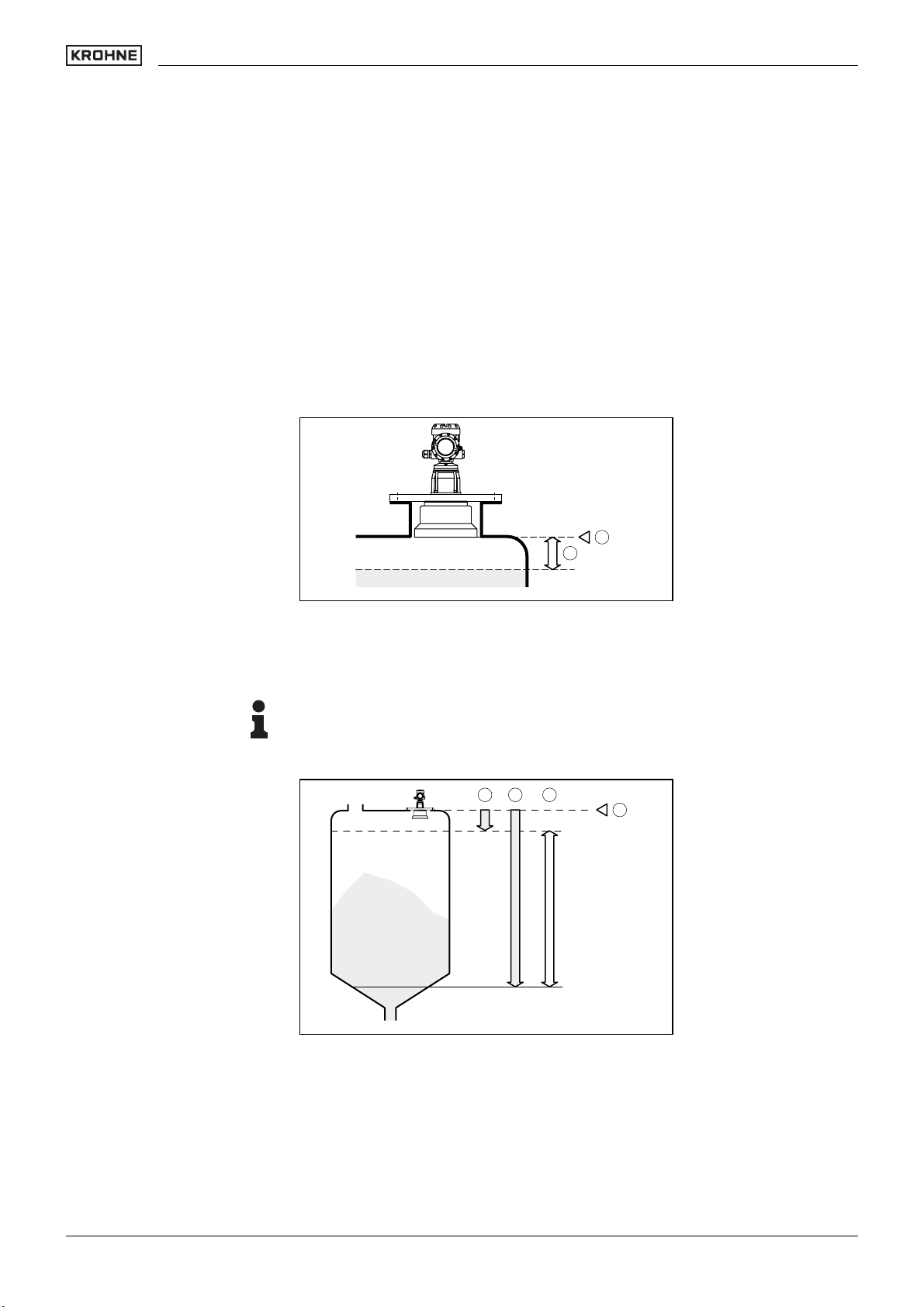
3 Mounting information
Measuring range
The reference plane for the measurement depends on the version. For the OPTISOUND 3040 C and 3050 C in flange version (version A) the lower edge of the flange
is the reference plane. For the versions with swivelling holder (versions B and C), with
threaded fitting (version D) as well as for OPTISOUND 3030 C, the lower edge of the
transducer is the reference plane. All statements concerning the measuring range as
well as the internal signal relate to this plane.
With all instruments, amin. distance from the lower edge of the flange - the so-called
dead zone, in which measurement is not possible - must be maintained. The exact
value of the dead zone, depending on the instrument version, is stated in the Technical data.
2
1
Fig. 3: Min. distance to the max. level on the example of an OPTISOUND 3030 C
1 Dead zone
2 Reference plane for the measurement
Note:
If the product reaches the transducer, buildup can form on it over a period of time and
later cause measurement errors.
132
4
100%
0%
Fig. 4: OPTISOUND 3040 C and 3050 version A – Measuring range
(operating range) and max. measuring distance
1 full (dead zone)
2 empty (max. measuring distance)
3 Measuring range
4 Reference plane
30601-EN-050816
8 Ultrasonic – Level measurement in solids
Page 9
Mounting information
Pressure/Vacuum
132
4
100%
0%
Fig. 5: OPTISOUND 3030 C … 3050 C version B, C, D – Measuring
range (operating range) and max. measuring distance
1 full (dead zone)
2 empty (max. measuring distance)
3 Measuring range
4 Reference plane
Gauge pressure in the vessel does not influence OPTISOUND. Low pressure or
vacuum, however damp the ultrasonic pulses. This influences the measuring result,
particularly if the level is very low. With pressures under -0,2 bar (-20 kPa) use a
different measuring principle, e.g. radar or guided radar (TDR).
Installation position
The mounting position of OPTISOUND 3030 C must be at least 200 mm (OPTISOUND 3040 C and 3050 C - at least 500 mm) from the vessel wall. If the sensor is
installed in the center of dished or spherical vessel tops, multiple echoes can result.
These can be faded out, however, through an appropriate adjustment.
If you cannot keep this distance, a false echo storage should be carried out during
setup. This applies particularly if buildup on the vessel wall is expected. In this case,
we recommend repeating the false echo storage later on with existing buildup.
30601-EN-050816
Ultrasonic – Level measurement in solids 9
Page 10
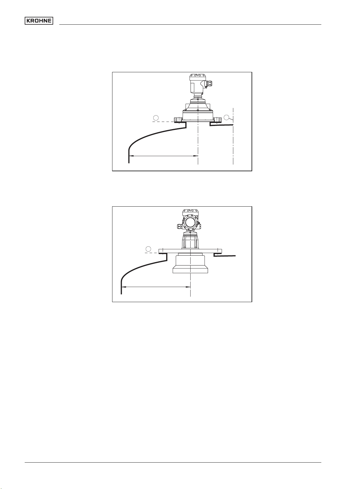
Mounting information
1
2
> 200 mm
Fig. 6: Mounting of OPTISOUND 3030 C on round vessel tops
1 Reference plane
2 Vessel center or symmetry axis
1
> 500 mm
Fig. 7: Mounting of OPTISOUND 3040 C and 3050 C on round vessel
tops
1 Reference plane
In vessels with conical bottom it can be advantageous to mount the sensor in the
center of the vessel, as measurement is then possible down to the lowest point of the
vessel bottom.
10 Ultrasonic – Level measurement in solids
30601-EN-050816
Page 11

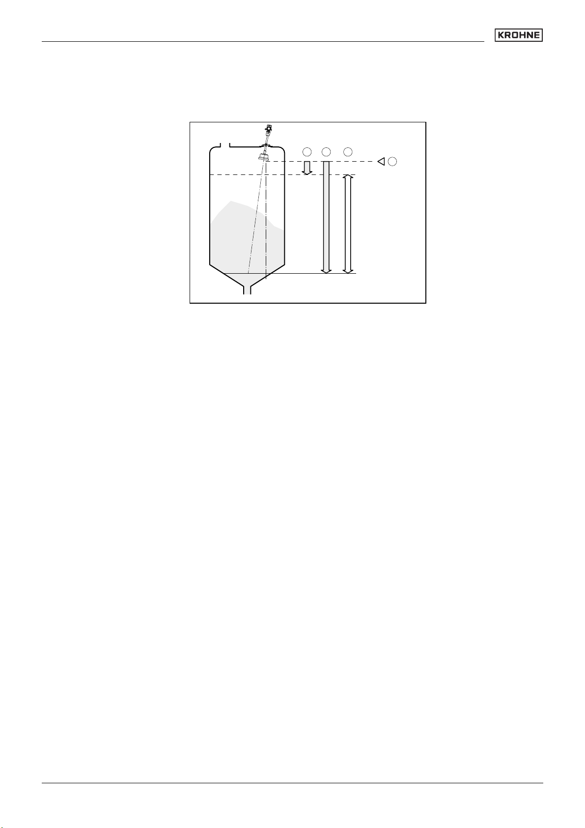
Mounting information
Fig. 8: OPTISOUND 3030 C on a vessel with conical bottom – Medium
liquid
Socket
Sensor orientation
30601-EN-050816
Fig. 9: OPTISOUND 3040 C on a vessel with conical bottom – Medium
solid
The transducer should be mounted preferably without socket, flush with the vessel
top.
Ifthereflective properties of the medium are good, you can mount OPTISOUND on a
socket piece higherthan the transducerlength. The socket end should be smoothand
burr-free, if possible, also rounded. A false echo storage is recommended.
With liquids, align the sensor as close to vertical as possible to achieve optimum
measuring results.
Fig. 10: Orientation in liquids
Ultrasonic – Level measurement in solids 11
Page 12

Mounting information
The version with swivelling holder is recommended for optimum orientation to solids.
Vessel installations
Material heaps
The ultrasonic sensor should be installed at a location where no installations cross the
ultrasonic beam.
Vessel installations such as, for example, ladders, limit switches, heating spirals,
struts, etc. can cause false echoes superimposed on the wanted echo. Make sure
when planning your measuring location that the ultrasonic signals have "free access"
to the measured product.
If there are existing vessel installations, a false echo storage should be carried out
during setup.
If large vessel installations such as struts or supports cause false echoes, these can
be attenuated through supplementary measures. Small, inclined sheet metal or plastic baffles above the installations scatter the ultrasonic signals and avoid direct false
echoes.
Fig. 11: Cover smooth profiles with deflectors
Large material heaps are detected with several sensors, which can be mounted on e.
g. traverse cranes. For this type of application, it is best to direct the sensor perpendicularly to the solid surface.
Fig. 12: Transducers on traverse crane
Inflowing material
The instrumentsmust not bemounted in orabove the fillingstream. Make sure that the
product surface and not the inflowing material is detected.
12 Ultrasonic – Level measurement in solids
30601-EN-050816
Page 13

Mounting information
Fig. 13: Inflowing liquid
Foam
Air flow
Heat fluctuations
Through the action of filling, stirring and other processes in the vessel, dense foams
which considerably damp the emitted signals may form on the product surface.
If foams are causing measurement errors, the sensor should be used in a standpipe
or, alternatively, the more suitable sensors with guided radar (TDR) should be used.
Guided radar is not influenced by foam generation and is particularly suitable for such
applications.
If there are strong air currents in the vessel, e.g. due to strong winds in outdoor
installations, or because of air turbulence, you should mount OPTISOUND in a standpipe or use a different measuring principle, e.g. radar or guided radar (TDR).
Strong heat fluctuations, e.g. caused by the sun, can cause measurement errors. In
this case, you should use a sun shield.
Fig. 14: Protection against the sun
30601-EN-050816
Ultrasonic – Level measurement in solids 13
Page 14

Electrical connection
4 Electrical connection
4.1 General requirements
The power supply range can differ depending on the instrument version. The exact
range is stated in the Technical data.
Take note of country-specific installation standards (e.g. the VDE regulations in Ger-
many) as well as prevailing safety regulations and accident prevention rules.
In hazardous areas you should take note of the appropriate regulations, conformity
and type approval certificates of the sensors and power supply units.
4.2 Supply voltage
4 … 20 mA/HART two-wire
4 … 20 mA/HART four-wire
Power supply and current signal are carried over the same two-wire connection cable.
The requirements on the power supply are stated in the Technical dataof this Product
Information manual.
Power supply and current output are carried on two separate connection cables.
The standard version can be operated with an earth-connected current output, the
Exd version must be operated w ith a floating output.
The instrument is designed in protection class I. To maintain this protection class, it is
absolutely necessary that the ground conductor be connected to the internal ground
conductor terminal.
4.3 Connection cable
The sensors are connected with standard cable without screen. An outer cable diameter of 5 … 9 mm ensures the seal effect of the cable entry.
If strongelectromagnetic interference is expected, screened cable shouldbe used for
the signal lines.
In Ex applications, the corresponding installation regulations must be noted for the
connection cable.
4.4 Connection of the cable screen and grounding
If screened cable is required, the cable screen must be connected on both ends to
ground potential. If potential equalisation currents are expected, the connection on
the evaluation side must be made via a ceramic capacitor (e.g. 1 nF, 1500 V).
14 Ultrasonic – Level measurement in solids
30601-EN-050816
Page 15

3
Single chamber housing
Electrical connection
4.5 Wiring plans OPTISOUND 3030 C
Double chamber hou-
sing – two-wire
Double chamber housing – 4 … 20 mA/HART
four-wire
12 5
Display
678
I2C
1
Fig. 15: Connection HART two-wire, Profibus PA, Foundation Fieldbus
1 Power supply and signal output
I2C
12
1
Fig. 16: Connection HART two-wire, Profibus PA, Foundation Fieldbus
1 Power supply and signal output
4...20mA IS
L1 N
GND
12
/ L
1 2
/ N
PE
4 ... 20 mA
Fig. 17: Connection 4 … 20 mA/HART four-wire
1 Supply voltage
2 Signal output
30601-EN-050816
Ultrasonic – Level measurement in solids 15
Page 16

3
Double chamber housing – 4 … 20 mA/HART
four-wire
Electrical connection
4.6 Wiring plans OPTISOUND 3040 C and 3050 C
L1 N
12
/ L
1 2
/ N
PE
Fig. 18: Connection 4 … 20 mA/HART four-wire
1 Supply voltage
2 Signal output
4...20mA IS
GND
4 ... 20 mA
30601-EN-050816
16 Ultrasonic – Level measurement in solids
Page 17

Adjustment
5 Adjustment
5.1 Adjustment, general
OPTISOUND can be adjusted with the following adjustment media:
l the indicating and adjustment module
l a HART handheld (4 … 20 mA/HART)
The entered parameters are generally saved in OPTISOUND, optionally also in the
indicating/adjustment module.
5.2 Compatibility acc. to NAMUR NE 53
OPTISOUND meet NAMUR recommendation NE 53.
The parameter adjustment of the basic sensor functions is independent of the soft-
ware version. The range of available functions depends on the respective software
version of the individual components.
30601-EN-050816
Ultrasonic – Level measurement in solids 17
Page 18

Adjustment
5.3 Adjustment with the indicating/adjustment module
Setup and indication
Adjustment
The indication and adjustment module can be plugged into OPTISOUND sensors. It
can be placed in four different positions on the instrument (each displaced by 90°).
Indication and adjustment are made via four keys and a clear, graphic-capable dot
matrix indication. The adjustment menu with language selection is clearly structured
and enables easy setup. After setup, the indicating/adjustment module serves as
indicating instrument: through the screwed cover with glass insert, measured values
can be read directly in the requested unit and presentation.
1
1.1
Fig. 19: Indicating and adjustment elements
1 LC display
2 Indication of the menu item number
3 Adjustment keys
2
3
Key functions
l
[OK] key:
- move to the menu overview
- confirm selected menu
- edit parameter
- save value
l [–>] key to select:
- menu change
- list entry
- editing position
l [+] key:
- modify value of a parameter
l [ESC] key:
- interrupt input
- jump to the next higher menu
30601-EN-050816
18 Ultrasonic – Level measurement in solids
Page 19

OPTISOUND 3030 C
OPTISOUND 3040 C and 3050 C
Technical data
6 Technical data
General data
Materials, wetted parts
- Mounting strap 1.4301
- Process fitting UP
- transducer diaphragm 316Ti (1.4571)
- Seal transducer/process fitting EPDM
Materials, non-wetted parts
- Compression flange PPH, 316L (1.4435)
- Housing plastic PBT (Polyester), Alu-die casting
powder-coated, 1.4435
- Seal ring between housing and hou-
sing cover
- Inspection window in housing cover
for indicating/adjustment module
- Ground terminal 316Ti/316L (1.4571/1.4435)
Weight
1)
Materials, wetted parts
- Flange PP or Alu
- swivelling holder, threaded fitting galvanized steel
- Transducer OPTISOUND 3040 CPA(1.4301 with StEx)
- Transducer OPTISOUND 3040 C and
3050 C
- Transducer diaphragm OPTISOUND
3040 C
- Transducer diaphragm OPTISOUND
3050 C
Materials, non-wetted parts
- Housing Alu die-casting powder-coated
- S
eal ring between housing and hou-
sing cover
- Inspection window in housing cover
for indicating/adjustment module
- Ground terminal 316Ti/316L (1.4571/1.4435)
- Transducer cable OPTISOUND 3040
C and 3050 C
Weight
2)
OPTISOUND 3040 C
- Version A 5.6 … 10.7 kg (12.3 … 23.6 lbs)
- Version B 6.9 … 9.7 kg (15.2 … 21.4 lbs)
- Version C 7.5 … 10.5 kg (16.5 … 23.1 lbs)
- Version D 4.7 … 6.9 kg (10.4 … 15.2 lbs)
Weight
3)
OPTISOUND 3050 C
- Version A 8.0 … 13.3 kg (17.6 … 29.3 lbs)
- Version B 8.7 … 10.3 kg (19.2 … 22.7 lbs)
- Version C 9.2 … 11.1 kg (20.3 … 24.5 lbs)
- Version D 6.5 … 7.5 kg (14.3 … 16.5 lbs)
NBR (stainless steel housing), silicone
(Alu/plastic housing)
Polycarbonate (UL746-
C listed)
2.7 … 5.7 kg (6 … 12.6 lbs)
UP
316Ti (1.4571)
Alu/PE foam rubber coating
silicone
Polycarbonate (UL746-C listed)
PUR (1.1082)
1)
Depending on the process fitting and housing.
2)
Depending on process fitting.
30601-EN-050816
3)
Depending on process fitting.
Ultrasonic – Level measurement in solids 19
Page 20

Technical data
Output variable
Output signal 4 … 20 mA/HART
Resolution 1.6 µA
Fault signal current output unchanged; 20.5 mA;
22 mA; <3.6 mA (adjustable)
Current limitation 22 mA
Load see load diagram in Power supply
Integration time (63 % of the input va-
0 … 999 s, adjustable
riable)
Rise time 500 ms (ti: 0 s, 0 … 100 %)
Fulfilled NAMUR recommendation NE 43
Integration time (63 % of the input va-
0 … 999 s, adjustable
riable)
ise time 500 ms (ti: 0 s, 0 … 100 %)
R
Input variable
Parameter distance between lower edge of the
transducer and product surface
Dead zone
- OPTISOUND 3030 C 0.6 m (2 ft)
- OPTISOUND 3040 C 1 m (3.3 ft)
- OPTISOUND 3050 C 0.8 m (2.6 ft)
Measuring range
- OPTISOUND 3030 C up to 15 m (49.2 ft) liquid/up to 7 m (23 ft)
solid
- OPTISOUND 3040 C up to 25 m (82 ft) liquid/up to 15 m
(49.2 ft) solid
- OPTISOUND 3050 C up to 45 m (147.
(82 ft) solid
6 ft) liquid/up to 25 m
Accuracy (similar to DIN EN 60770-1)
Reference conditions acc. to
DIN EN 61298-1
- Temperature 18 … 30°C (64 … 86°F)
- Relative humidity 45 … 75 %
- Atmospheric pressure 860 … 1060 mbar (86 … 106 kPa/
12.5 … 15.4 psi)
Characteristic curve deviation and measurement characteristics
Average temperature coefficient of the
zero si gnal (temperature error)
Resolution, general max. 1 mm
4)
Relating to the nominal range, incl. hysteresis and repeatability, determined acc. to the limit point
method.
20 Ultrasonic – Level measurement in solids
0.06 %/10 K
4)
30601-EN-050816
Page 21

OPTISOUND 3030 C
Technical data
Ultrasonic frequency/Beam angle
- OPTISOUND 3030 C 35 kH z/5.5°
- OPTISOUND 3040 C 30 kH z/4°
- OPTISOUND 3050 C 18 kH z/5°
Interval >2 s (dependent on the parameter ad-
justment)
Adjustment time
5)
>3 s (dependent on the parameter ad-
justment)
Accuracy better than 0.2 % or ±6 mm (see res-
pective diagram)
30 mm
OPTISOUND 3040 C
20 mm
10 mm
6 mm
-6 mm
-10 mm
-20 mm
-30 mm
Fig. 20: Accuracy diagram OPTISOUND 3030 C
50 mm
25 mm
6 mm
-6 mm
-25 mm
5 m 15 m 20 m
15 m8 m6 m4 m 12 m10 m3 m
25 m10 m3 m
-50 mm
Fig. 21: Accuracy diagram OPTISOUND 3040 C – Version A
30601-EN-050816
5)
Time to output the correct level (with max. 10 % deviation) after a sudden level change.
Ultrasonic – Level measurement in solids 21
Page 22

Technical data
50 mm
25 mm
OPTISOUND 3050 C
6 mm
-6 mm
-25 mm
-50 mm
5 m 15 m 20 m
Fig. 22: Accuracy diagram OPTISOUND 3040 C – Versions B, C, D
90 mm
60 mm
30 mm
6 mm
-6 mm
-30 mm
25 m10 m3 m
45 m30 m15 m3 m
-60 mm
-90 mm
Fig. 23: Accuracy diagram OPTISOUND 3050 C – Version A
22 Ultrasonic – Level measurement in solids
30601-EN-050816
Page 23

Technical data
90 mm
60 mm
30 mm
6 mm
-6 mm
-30 mm
-60 mm
-90 mm
Fig. 24: Accuracy diagram OPTISOUND 3050 C – Versions B, C, D
45 m30 m15 m3 m
Ambient conditions
Ambient, storage and transport tem-
perature
- without indicating and adjustment
-40 … +80°C (-40 … +176°F)
module
- the indicating and adjustment module -20 … +70°C (-4 … +158°F)
Process conditions
Vessel pressure
- Input variable OPTISOUND 3030 C
with compression flange
- OPTISOUND 3030 C with mounting
strap
- OPTISOUND 3040 C and 3050 C -20 … 50 kPa (-
- OPTISOUND 3040 C and 3050 C –
Version A with PP fl
ange
-20 … 100 kPa (-
0.2 … 1 bar/-2.9 … 14.5 psi)
0 k Pa (0 bar/0 psi), because no sealing
possibility
0.2 … 0.5 bar/-2.9 … 7.3 psi)
0 k Pa (0 bar/0 psi)
Process temperature (transducer tem-
-40 … +80°C (-40 … +176°F)
perature)
30601-EN-050816
Vibration resistance mechanical vibrations with 4 g and
5 … 100 Hz
6)
Tested acc. to the regulations of German Lloyd, GL directive 2
6)
Ultrasonic – Level measurement in solids 23
Page 24

Technical data
Electromechanical data
Cable entry
- Single chamber housing l 1x cable entry M20x1.5 (cable-ø
5 … 9 mm), 1x blind stopper
M20x1.5
or:
l 1x closing cap ½ NPT, 1xblind
stopper ½ NPT
- Double chamber housing
l 1x cable entry M20x1.5 (cable-ø
5 … 9 mm), 1x blind stopper
M20x1.5
or:
l 1x closing cap ½ NPT, 1xblind
stopper ½ NPT
Spring-loaded terminals for wire cross sections up to 2.5 mm²
24 Ultrasonic – Level measurement in solids
30601-EN-050816
Page 25

Technical data
Indicating and adjustment module
Power supply and data transmission through sensor via gold-plated sliding
contacts (I²C bus)
Indication LC display in full dot matrix
Adjustment elements 4 keys
Protection
- unassembled IP 20
- mounted into the sensor without cover IP 40
Materials
- Housing ABS
- Inspection window Polyester foil
Supply voltage
Power supply – two-wire instrument
- non-Ex instrument 14 ... 36 VDC
- EEx ia instrument 14 ... 30 VDC
Permissible residual ripple
- < 100 Hz Uss < 1 V
- 100 Hz ... 10 kHz Uss < 10 mV
Load see diagram
Ω
1000
750
500
250
1
2
3
4
14
Fig. 25: Voltage diagram
1 HART load
2 Voltage limit EEx ia instrument
3 Voltage limit non-Ex instrument
4 Supply voltage
1816 20 22 24 26 28 30 32 34 36
V
Supply voltage – four-wire instrument 20 ... 72 VDC, 20 ... 253 VAC, 50/60 Hz
Power consumption – four-wire instru-
max. 4 VA; max. 2.1 W
ment
30601-EN-050816
Ultrasonic – Level measurement in solids 25
Page 26

Technical data
Electrical protective measures
Protection
- Housing OPTISOUND 3030 CIP66/IP 68 (0.2 bar)
- Housing OPTISOUND 3030 C - 3050
C
- Transducer IP 68
Overvoltage category III
Protection class
- two-wire, Profibus PA, Foundation
Fieldbus
- four-wire I
IP 66/IP 67
II
7)
Approvals OPTISOUND 3040 C and 3050 C
8)9)
ATEX ATEX II 1/2DIP66 T
CE conformity
EMC (89/336/EWG) Emission EN 61326: 1997 (class A),
susceptibility EN 61326: 1997/A1: 1998
LVD (73/23/EWG) EN 61010-1: 2001
7)
Requirement to maintain the housing protection is the suitable cable.
8)
Deviating data with Ex applications: see separate safety instructions.
9)
Depending on order specification.
26 Ultrasonic – Level measurement in solids
30601-EN-050816
Page 27

Dimensions
7 Dimensions
Housing
M20x1,5/
½ NPT
~ 116mm
9
(4
/16")
ø 84mm
(3
5
/16")
")
64
/
31
114mm
(4
M20x1,5
~ 69mm
23
(2
M20x1,5/
½ NPT
~ 69mm
23
(2
/32")
/32")
ø 77mm
1
(3
/32")
")
32
/
13
112mm
(4
M20x1,5/
½ NPT
ø 77mm
1
(3
/32")
1 2 3 4
")
64
/
39
117mm
(4
~ 87mm (3 27/64")
M20x1,5/
½ NPT
ø 84mm
5
(3
/16")
")
32
/
23
120mm (4
Fig. 26: Housing versions (with integrated indicating/adjustment module the housing height or width is
increased by 9 mm/0.35 in)
1 Plastic housing
2 Stainless steel housing
3 Aluminium double chamber housing
4 Aluminium housing
OPTISOUND 3030 C
1
130mm (5
/8")
")
64
/
43
1
195mm (7
")
64
/
41
118mm (4
41
118mm (4
ø 148mm (5 53/64")
ø 158mm (6
/64")
7
/32")
M8x12
DN100/ANSI4"
2
Fig. 27: OPTISOUND 3030 C
1 Mounting strap
2 Compression flange
3 Dead zone: 0.6 m (2 ft)
4 Meas. range: in liquids up to 15 m (49.2 ft), in solids up to 7 m (23 ft)
3 4
30601-EN-050816
Ultrasonic – Level measurement in solids 27
Page 28

Dimensions
OPTISOUND 3040 C
130mm (51/8")
1
")
64
/
29
240mm (9
")
64
/
21
110mm (4
ø189mm (7 7/16")
k
D
D
DN 50 PN16/40
DN 80 PN16/40
DN 200 PN16
DN 250 PN16
2" 150lb
3" 150lb
8" 150lb
10" 150lb
165mm
200mm
340mm
405mm
D
6"
1
7
/2"
1
/2"
13
16"
20mm
24mm
24mm
26mm
3
15
1
1
2
b
2
3
")
64
/
21
°
5
1
.
x
a
m
9
1
)
"
/
(
34
440mm (17
D
k
k
b
125mm
160mm
295mm
355mm
b
k
3
/4"
/4"
4
/16"
6"
1
3
/8"
11
3
/16"
14
1
d
ø18mm
4x
ø18mm
8x
ø22mm
12x
ø26mm
12x
d
3
ø
/4"
4x
3
4x
/4"
ø
12x
7
/8"
8x
ø
ø 1"
/4"
/4"
>ø200mm
7
(7
/8")
34
")
8
/
7
250mm (9
Fig. 28: OPTISOUND 3040 C
1 Version A
2 Version B
3 Dead zone: 1 m (3.3 ft)
4 Measuring range: with liquids up to 25 m (82 ft), with solids up to 15 m (49.2 ft)
30601-EN-050816
28 Ultrasonic – Level measurement in solids
Page 29

Dimensions
OPTISOUND 3040 C
150mm (5 29/32")
1 2
")
32
/
21
220mm (8
>ø200mm
7
/8")
(7
")
32
/
9
") 312mm (12
8
/
7
G1A
")
64
/
45
18mm
(
34
")
8
/
5
143mm (5
")
64
/
55
149mm (5
250mm (9
D
b
DN 50 PN16/40
DN 80 PN16/40
DN 200 PN16
DN 250 PN16
165mm
200mm
340mm
405mm
20mm
24mm
24mm
26mm
k
125mm
160mm
295mm
355mm
12x
12x
4x
8x
d
ø18mm
ø18mm
ø22mm
ø26mm
2" 150lb
3" 150lb
8" 150lb
10" 150lb
13
D
b
3
6"
/4"
1
/2"
7
1
/2"
16"
4
15
/16"
1
1
/8"
11
3
1
14
/16"
Fig. 29: OPTISOUND 3040 C
1 Version C
2 Version D
3 Dead zone: 1 m (3.3 ft)
4 Measuring range: with liquids up to 25 m (82 ft), with solids up to 15 m (49.2 ft)
k
3
/4"
6"
3
1
d
3
ø
/4"
4x
3
/4"
ø
4x
7
12x
ø
/8"
8x
ø 1"
/4"
/4"
30601-EN-050816
Ultrasonic – Level measurement in solids 29
Page 30

Dimensions
OPTISOUND 3050 C
130mm (51/8")
1 2
")
64
/
29
240mm (9
°
5
1
.
x
a
m
9
1
)
"
/
(
2
3
")
64
/
b
21
")
64
/
59
125mm (4
DN 50 PN16/40
DN 80 PN16/40
DN 200 PN16
DN 250 PN16
2" 150lb
3" 150lb
8" 150lb
10" 150lb
ø244mm (9 39/64")
k
D
D
165mm
20mm
200mm
24mm
340mm
24mm
405mm
26mm
D
6"
15
7 1/2"
1
/2"
13
1
16"
1
3
3
b
b
/4"
/16"
1
/8"
/16"
k
125mm
160mm
295mm
355mm
k
3
/4"
4
6"
3
/4"
11
1
14
/4"
12x
12x
4x
8x
12x
d
ø18mm
ø18mm
ø22mm
ø26mm
d
4x
4x
8x
ø
ø
ø
ø 1"
3
/4"
3
/4"
7
/8"
>ø250mm
7
(9
/8")
D
k
Fig. 30: OPTISOUND 3050 C
1 Version A
2 Version B
3 Dead zone: 0.8 m (2.6 ft)
4 Measuring range: with liquids up to 45 m (147.6 ft), with solids up to 25 m (82 ft)
34
440mm (17
")
8
/
5
270mm (10
30 Ultrasonic – Level measurement in solids
30601-EN-050816
Page 31

OPTISOUND 3050 C
150mm (5 29/32")
1 2
")
32
/
21
220mm (8
>ø250mm
7
/8")
(9
")
32
/
9
") 312mm (12
8
/
5
270mm (10
G1A
")
64
/
45
18mm
(
34
")
8
/
5
143mm (5
")
2
/
1
165mm (6
DN 50 PN16/40
DN 80 PN16/40
DN 200 PN16
DN 250 PN16
165mm
200mm
340mm
405mm
20mm
24mm
24mm
26mm
k
125mm
160mm
295mm
355mm
12x
12x
4x
8x
d
ø18mm
ø18mm
ø22mm
ø26mm
2" 150lb
3" 150lb
8" 150lb
10" 150lb
13
D
b
k
3
6"
1
15
/2"
7
1
1
/2"
16"
1
3
/4"
4
/16"
6"
1
/8"
11
3
14
/16"
D
b
Fig. 31: OPTISOUND 3050 C
1 Version C
2 Version D
3 Dead zone: 0.8 m (2.6 ft)
4 Measuring range: with liquids up to 45 m (147.6 ft), with solids up to 25 m (82 ft)
d
3
12x
ø
/4"
4x
3
/4"
ø
4x
7
ø
/8"
8x
ø 1"
/4"
3
/4"
1
/4"
30601-EN-050816
Ultrasonic – Level measurement in solids 31
 Loading...