

Page 1
Operating Instructions
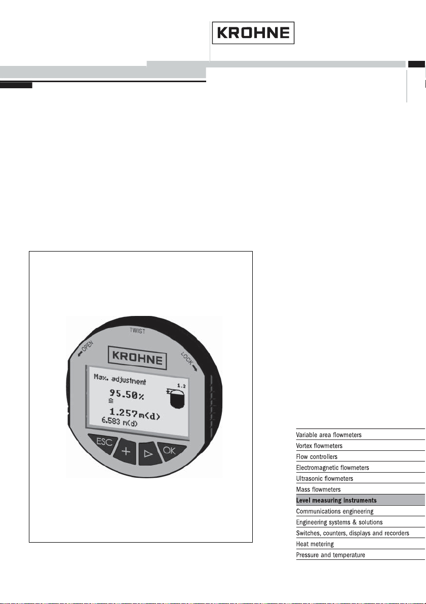
Indicating/adjustment module for OPTISOUND sensors
Page 2

Contents
Contents
1 About this document
1.1 Contents .........................
1.2 Target group ......................
1.3 Symbolism used....................
2 For your safety
2.1 Authorised personnel ................
2.2 Appropriate use ....................
2.3 Warning about misuse ...............
2.4 General safety instructions ............
2.5 CE conformity .....................
2.6 Compatibility acc. to NAMUR NE 53 .....
2.7 Safety information for Ex areas .........
3 Product description
3.1 Configuration ......................
3.2 Principle of operation ................
3.3 Adjustment........................
3.4 Storage and transport ................
4
4
4
6
6
6
6
6
7
7
8
9
10
10
4 Mounting
4.1 Mounting procedure .................
11
5 Set up
5.1 Adjustment system ..................
5.2 General functions ...................
5.3 Special functions – 4 … 20 mA/HART ....
5.4 Menu schematic ....................
13
14
21
23
6 Maintenance and fault rectification
6.1 Maintenance ......................
6.2 Instrument repair ...................
26
26
7 Dismounting
7.1 Dismounting procedure ...............
7.2 Disposal .........................
2 Indicating/adjustment module for OPTISOUND sensors
27
27
30603-EN-050401
Page 3

8 Supplement
8.1 Technical data .....................
8.2 Dimensions .......................
Contents
28
29
30603-EN-050401
Indicating/adjustment module for OPTISOUND sensors 3
Page 4
About this document
1 About this document
1.1 Contents
This operating instructions manual has all the information you need for quick setup and safe operation of the
indicating/adjustment module. Please read this manual
before you start setup.
1.2 Target group
This operating instructions manual is directed to trained
personnel. The contents of this manual should be made
available to these personnel and put into practice by
them.
1.3 Symbolism used
Information, tip, note
This symbol indicates helpful additional information.
Caution, warning, danger
This symbol informs you of a dangerous situation that
could occur. Ignoring this cautionary note can impair the
person and/or the instrument.
Ex applications
This symbol indicates special instructions for E xapplications.
l List
The dot set in front indicates a list with no implied
sequence.
à Action
This arrow indicates a single action.
4 Indicating/adjustment module for OPTISOUND sensors
30603-EN-050401
Page 5

1 Sequence
Numbers set in front indicate successive steps in a
procedure.
About this document
30603-EN-050401
Indicating/adjustment module for OPTISOUND sensors 5
Page 6

For your safety
2 For your safety
2.1 Authorised personnel
All operations described in this operating instructions
manual must be carried out only by trained and
specialist personnel authorised by the operator. For
safety and warranty reasons, any internal work on the
instruments must be carried out only by personnel
authorised by the manufacturer.
2.2 Appropriate use
The indicating and adjustment module is a pluggable
unit for OPTISOUND level sensors.
2.3 Warning about misuse
Inappropriate or incorrect use of the instrument can give
rise to application-specific hazards, e.g. vessel overfill or
damage to system components through incorrect
mounting or adjustment.
2.4 General safety instructions
The indicating/adjustment module is a high-tech instrument requiring the strict observance of standard
regulations and guidelines. The user must take note of
the safety instructions in this operating instructions
manual, the country-specific installation standards (e.g.
the VDE regulations in Germany) as well as all prevailing
safety regulations and accident prevention rules.
2.5 CE conformity
The indicating and adjustment module is in CE
conformity to EMC (89/336/EWG) and NSR (73/23/
EWG).
6 Indicating/adjustment module for OPTISOUND sensors
30603-EN-050401
Page 7

For your safety
Conformity has been judged acc. to the following
standards:
l EMC:
- Emission EN 61326: 1997
- Susceptibility EN 61326: 1997 + A1:1998
l NSR: EN 61010-1: 2001
2.6 Compatibility acc. to NAMUR NE 53
The indicating/adjustment module meets NAMUR recommendation NE 53.
The parameter adjustment of the basic sensor functions
is independent of the software version. The available
functions depend on the appropriate software version of
the single components.
2.7 Safety information for Ex areas
Please note the Ex-specific safety information for
installation and operation in Ex areas. These safety
instructions are part of the operating instructions manual
and come with the Ex-approved instruments.
30603-EN-050401
Indicating/adjustment module for OPTISOUND sensors 7
Page 8

Product description
3 Product description
3.1 Configuration
Scope of delivery
Configuration
The scope of delivery encompasses:
l Indicating/adjustment module
l Documentation
- this operating instructions manual.
The indicating/adjustment module consists of a display
with full dot matrix as well as four keys for adjustment.
1
2
Fig. 1: Indicating/adjustment module
1 Display
2 Keys
8 Indicating/adjustment module for OPTISOUND sensors
30603-EN-050401
Page 9
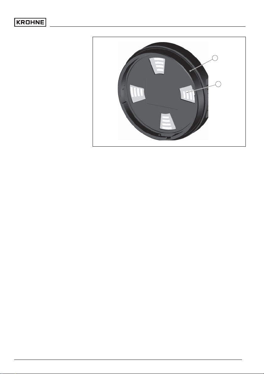
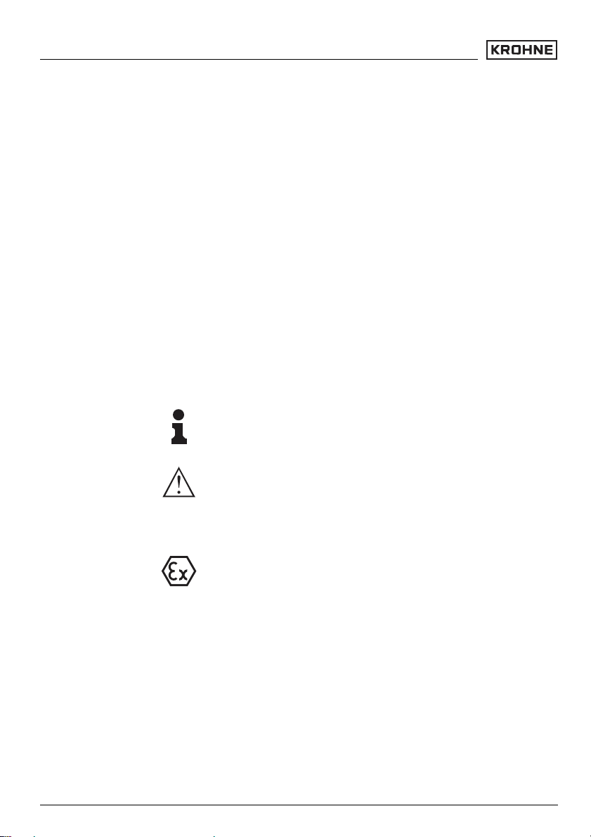
Fig. 2: Rear of the indicating/adjustment module
1 integrated seal ring
2 gold-plated contact path
3.2 Principle of operation
Product description
1
2
Area of application
The indicating/adjustment module is used for measured
value indication, adjustment and diagnosis for the
following OPTISOUND sensors:
l OPTISOUND 3010 C
l OPTISOUND 3020 C
l OPTISOUND 3030 C
l OPTISOUND 3040 C
l OPTISOUND 3050 C
The indicating/adjustment module is integrated into the
respective sensor housing. After installation, sensor as
well as module without housing cover are splash-proof.
Power supply
Power supply directly by the respective sensor. An
additional connection is not necessary.
30603-EN-050401
Indicating/adjustment module for OPTISOUND sensors 9
Page 10

Product description
3.3 Adjustment
Adjustment is carried out via the integrated keys. The
entered parameters are generally saved in the respective sensor. With a copy function, parameters can be
loaded into the indicating/adjustment module.
3.4 Storage and transport
Packaging
Storage and transport
temperature
Your instrument was protected by packaging during
transport. Its capacity to handle normal loads during
transport is assured by a test acc. to DIN EN 24180.
The packaging of standard instruments consists of
environment-friendly, recyclable cardboard. For special
versions PE foam or PE foil is also used. Dispose of the
packaging material via specialised recycling companies.
l Storage and transport temperature see "Supplement
– Technical data – Ambient conditions"
l Relative humidity 20 … 85 %
10 Indicating/adjustment module for OPTISOUND sensors
30603-EN-050401
Page 11

4 Mounting
4.1 Mounting procedure
Mounting
Mounting/dismounting the
indicating/adjustment module
The indicating/adjustment module can be mounted or
dismounted at any time. An interruption of the power
supply is not necessary.
Proceed as follows:
1 Unscrew the housing cover
2 Place the indicating/adjustment module to the re-
quested position on the electronics
Information:
Four different positions are possible, each displaced by
90°.
Fig. 3: Installation of the indicating/adjustment module
3 Press the indicating/adjustment module lightly onto
the electronics and turn it to the right until it snaps in
4 Screw housing cover with inspection window tightly
back on
30603-EN-050401
Indicating/adjustment module for OPTISOUND sensors 11
Page 12

Mounting
Note:
If you intend to retrofit OPTISOUND with an indicating/
adjustment module for continuous measured value
indication, a higher cover with an inspection glass is
required.
Dismounting is carried out in reverse order.
12 Indicating/adjustment module for OPTISOUND sensors
30603-EN-050401
Page 13

5 Set up
5.1 Adjustment system
Set up
Key functions
Adjustment system
1
Fig. 4: Indicating and adjustment elements
1 LC display
2 Indication of the menu item number
3 Adjustment keys
[OK] key:
l
1.1
2
3
- move to the menu overview
- confirm selected menu
- edit parameter
- save value
l [–>] key to select:
- menu change
- list entry
- editing position
l [+] key:
- modify value of a parameter
l [ESC] key:
- interrupt input
- jump to the next higher menu
The sensor is adjusted via the four keys of the indicating
and adjustment module. The LC display indicates the
individual menu items. The functions of the individual
30603-EN-050401
Indicating/adjustment module for OPTISOUND sensors 13
Page 14

Set up
keys are shown in the above illustration. Approx. 10
minutes after the last pressing of a key, an automatic
reset to measured value indication is triggered. Any
values not confirmed with [OK] will not be saved.
5.2 General functions
Introduction
Measured value indication
OPTISOUND ultrasonic sensors have various functions.
Therefore they can be adapted perfectly to the respec-
tive application. These functions are structured in menu
form. Some of the functions are sensor-specific. These
are described in the operating instructions manual of the
respective sensor. Other functions, however, have
general character, i.e. they are available in sensors with
different measuring principles.
The general functions are described in this paragraph.
The functions of the indicating/adjustment module are
determined by the sensor and correspond to the
respective software version of the sensor.
Information:
The respective menu item number differs depending on
the sensor type and signal output.
The following presentations are available in the measured value display:
l Level as digital value, sensor TAG
l Level as digital value and bar graph, sensor TAG
With [–>] you select the different presentations of the
measured value. From all presentations you reach the
menu overview with [OK]. With [ESC] you return from
the menu overview to the measured value display.
Menu overview
In the menu overview you select the respective menu
with [–>] and finally reach it with [OK]. Then the
individual menu items are available.
>
Basic adjustment 1
Display
Diagnostics
Service
Info
14 Indicating/adjustment module for OPTISOUND sensors
30603-EN-050401
Page 15

Set up
Damping
Linearization curve
To damp process-dependent measured value fluctuations, you have to set an integration time of 0 … 999 sin
this menu item.
Damping
In this menu item you select the linearization curve:
l linear
l Cylindrical tank
l Spherical tank
l User programmable
User programmable means: Switching on a linearization
curve programmed via PC and PACTware™
The linearization curve relates height and volume. It
takes the vessel geometry for the measured value
display and the current output into account.
Linearization
curve
linear
Edit senor TAG
In the menu item "Sensor TAG" you edit a 12-digit
measurement loop character. The character set comprises:
l Letters from A … Z
l Numbers from 0 … 9
l Special characters +,-,/,–
Sensor
TAG
Sensor
Peak values
Min. and max. measured values are saved in the sensor.
The values are displayed in the menu item "Peak
values".
l Min. and max. distance in m(d)
l Min. and max. temperature
30603-EN-050401
Indicating/adjustment module for OPTISOUND sensors 15
Page 16

Set up
Peak values
Meas. reliability
Sensor status
Choose curve
When using sensors working acc. to the non-contact
measuring principle, the measurement can be influen-
ced by the respective process conditions. In this menu
item, the reliability of the level echo is displayed in dB.
The reliability is signal strength minus noise. The higher
the value, the more reliable the measurement.
Indication "OK" or flashing error message, e.g. "E013".
In addition, the error appears in clear text in the
measured value display.
Meas. reliability
Sensor status
The signal curves enable a first rough evaluation of the
measurement. The following curves are available:
l Echo curve
l False echo curve
l Trend curve.
The echo curve shows the echoes with signal strength in
db over the distance.
The false echo curve shows the saved false echoes
(see menu "Service") of the empty vessel with signal
strength in "dB" over the measuring range.
Choose curve
Curve presentation
With a comparison of echo and false echo curve a more
detailed statement of the reliability can be made. The
selected curve is updated permanently. With the [OK]
key, a submenu with zoom functions is opened.
Available with the echo and false echo curve:
16 Indicating/adjustment module for OPTISOUND sensors
30603-EN-050401
Page 17

Set up
l "X-Zoom": Zoom function for the meas. distance
l "Y-Zoom": 2, 5 and 10-times magnification of the
signal in "dB"
l "Unzoom": Resetting the presentation to the nominal
measuring range with single magnification
Available with the trend curve:
l "X-Zoom": Splitting in minutes, hours or days
l "Stop/Start": Interruption of a recording or start of a
new recording
l "Unzoom": Resetting the splitting to minutes
echo curve
Simulation of measured
values
In this menu item you simulate individual level values via
the current output. Then the signal path can be tested, e.
g. via connected indicating instruments or the input card
of the processing system.
The following simulation factors are available:
l Percent
l Current
l Distance.
How to start the simulation:
1 Push [OK]
2 Select the requested simulation factor with [–>] and
confirm with [OK]
3 Set the requested value with [+] and [–>].
4 Push [OK]
The simulation is activated and a respective current of
4 … 20 mA is outputted.
How to interrupt the simulation:
à Push [ESC]
Information:
The simulation is interrupted automatically 10 minutes
after the last key has been pushed.
30603-EN-050401
Indicating/adjustment module for OPTISOUND sensors 17
Page 18

Set up
Simulation
Simulation
start?
Reset
With the reset function, modified values are reset. Three
subfunctions are available:
l Basic adjustment
- Reset of the values modified with the indicating/
adjustment module to the sensor-specific basic
setting (see chart)
l Factory setting
- Like basic setting, but also reset of special
parameters modified with PACTware™ to delivery status
l Peak values measured value and temperature
- Reset of the min./max. values of level and
temperature to the current values
Reset values basic setting
Menu Menu item Ultrasonic
Basic setting Units of measurement deleted
Min. adjustment upper dead zone depending on instru-
Max. adjustment end nominal measuring range
Linearization curve linear
Sensor-TAG Sensor
Display Displayed value 1 Distance
Scaling 0%=0.0, 100%=100.0
Service Current output
ment
Output mode: 4-20mA
Failure mode: < 3.6 mA
min. current3.8 mA
18 Indicating/adjustment module for OPTISOUND sensors
30603-EN-050401
Page 19

Reset
Reset
select?
Set up
Units of measurement
Language
Copy sensor data
In this menu item you select the internal calculating unit
of the sensor: m(d) or ft(d).
Units of measurement
m(d)
The sensor is already set to the ordered national
language. In this menu item you can change the
language. The following languages are available:
l Deutsch
l English
l Français
l Espanõl
l Pycckuu.
Language
Deutsch
With this function
l data are read from the sensor
l data are written into the sensor.
The data are permanently saved in an EEPROM
memory in the indicating/adjustment module and remain
there even in case of voltage failure. From there, they
can be written in one or several sensors and kept as a
backup for a possible sensor exchange. When writing
the data into the sensor, the instrument type from which
the data originate as well as the TAG no. of that sensor
are displayed.
30603-EN-050401
Indicating/adjustment module for OPTISOUND sensors 19
Page 20

Set up
Sensor data
copy?
PIN
Info
In this menu item, the PIN is activated/deactivated
permanently. Entering a 4-digit PIN protects the sensor
data against unauthorized access and unintentional
modifications. If the PIN is activated permanently, it can
be deactivated temporarily (i.e. for approx. 60 min.) in
any menu item. The instrument is delivered with the PIN
set to 0000.
PIN
Disable
permanently?
Only the following functions are permitted with activated
PIN:
l Select menu items and show data
l Read data from the sensor into the indicating/
adjustment module.
In this menu item the most important sensor information
can be displayed:
l Instrument type, e.g. OPTISOUND 3010 C
l Serial number: 8-digit number, e.g. 12345678
l Date of manufacture: Date of the factory calibration,
e.g. 26. September 2004
l Software version: Edition of the sensor software, e.g.
3.22.00
l Date of last change using PC: Date of the last change
of sensor parameters via PC, e.g. 26. September
2004
l Sensor details, e.g. approval, process fitting, seal,
meas. range, electronics, housing, cable entry, plug,
cable length etc.
30603-EN-050401
20 Indicating/adjustment module for OPTISOUND sensors
Page 21

Sensor type
Serial
number
Date of manufacture
Software
revision
Date of last
change
using PC
Sensor
details
5.3 Special functions – 4 … 20 mA/HART
Set up
Introduction
The 4 … 20 mA/HART special functions are briefly
described in this paragraph. The respective range of
functions of the indicating and adjustment module is
determined by the sensor and the sensor software
revision.
Display
In the menu item "Display" you can define how the
measured value should be presented on the display.
The following indication values are available:
l Height
l Distance
l Current
l Scaled
l Percent
l Lin. percent
The selection "scaled" opens the menu items "Display
unit" and "Scaling". In "Display unit" there are the
following options:
l Height
30603-EN-050401
Indicating/adjustment module for OPTISOUND sensors 21
Page 22

Set up
l Mass
l Flow
l Volume
l Without unit.
Depending on the selection, the different units will be
available.
In the menu item "Scaling", the requested numerical
value with decimal point is entered for 0 % and 100 % of
the measured value.
There is the following relation between the indication
value in the menu "Display" and the adjustment unit in
the menu "Basic adjustment":
l With ultrasonics, the indication value "Distance"
means: Presentation of the measured value in the
selected adjustment unit, e.g. m(d).
Displayed value
scaled
Indication
unit
Volume
l
Scaling
0 %=0.0 l
100 %=100.0 l
Current output
In the menu item "Current output" you determine the
behaviour of the current output during operation and in
case of failure. The following options are available:
22 Indicating/adjustment module for OPTISOUND sensors
30603-EN-050401
Page 23

Set up
Current output
Output mode
Failure mode
Min. current
1)
2)
4 … 20 mA
20 … 4 mA
Hold value
20.5 mA
22.0 mA
<3.6 mA
3.8 mA
4 mA
The values in bolt font represent the data of the factory
setting.
In HART multidrop mode, the current is constantly 4 mA.
This value does not change even in case of failure.
Current output
Output mode 4-20 mA
Failure mode: 22mA
Min-current 3.8mA
HART mode
HART offers standard and multidrop mode3). In multidrop mode up to 15 sensors can be operated on one
two-wire cable.
In this menu item you determine the HART mode and
enter the address with multidrop.
HART mode
standard
Address 0
1)
Value of the current output in case of failure, e.g. if no valid
measured value is delivered.
2)
The current never falls below this value during operation.
3)
In multidrop mode, the 4 … 20 mA signal of the HART sensor is
switched off. The sensor consumes a constant current of 4 mA.
The meas. signal is only transmitted as digital HART signal.
30603-EN-050401
Indicating/adjustment module for OPTISOUND sensors 23
Page 24

Set up
Basic adjustment
>
Basic adjustment
Display
Diagnostics
Service
Info
5.4 Menu schematic
1
Min. adjustment
0.00 %
=
4.000 m(d)
3.000 m(d)
Damping
0 s
Display
Basic adjustment
>
Display
Diagnostics
Service
Info
Displayed value
scaled
Diagnostics
Basic adjustment
Display
>
Diagnostics
Service
Info
1.1
1.5
2.1
2
3
Max. adjustment
100.00 %
=
1.000 m(d)
2.000 m(d)
Linearization curve
linear
Display units
Volume
m³
1.2
1.6
2.2
Medium
Liquid
Sensor-TAG
Scaling
0%=0.0m³
100%=100m³
Sensor
1.3
1.7
2.3
Vessel form
Storage tank
1.4
Peak values
Distance-min: 0.234m(d)
Distance-max: 5.385m(d)
3.1
Meas. reliability
8db
Sensor status
OK
3.2
Choose curve
echo curve
3.3
echo curve
Presentation of
3.4
echo curve
24 Indicating/adjustment module for OPTISOUND sensors
30603-EN-050401
Page 25

Service
Basic adjustment
Display
Diagnostics
>
Service
Info
Set up
4
False echo storage
Change?
Reset
Copy sensor data
Copy sensor data?
Info
Basic adjustment
Display
Diagnostics
Service
>
Info
Sensor type
OPTISOUND 30x0 C
>
Serial number
12345678
Reset
select?
4.1
4.5
4.9
5.1
5
Addl. adjustments
none
Units of measurement
m(d)
select?
PIN
Enable?
Date of manufacture
26. March 2004
Software version
3.12.xx
4.2
4.6
4.10
5.2
Current output
Output mode 4-20 mA
Failure mode <3.6 mA
min. current3.8 mA
Language
Deutsch
Date of last change
using PC
26. March 2004
4.3
4.7
5.3
Simulation
Simulation
start?
HART mode
standard
Address 0
Sensor details
display
4.4
4.8
5.4
Now
30603-EN-050401
Indicating/adjustment module for OPTISOUND sensors 25
Page 26

Maintenance and fault rectification
6 Maintenance and fault rectification
6.1 Maintenance
When used appropriately under normal condition, the
indicating and adjustment module is maintenance-free.
6.2 Instrument repair
If it is necessary to repair, please proceed as follows:
You can download a return form from our Internet
homepage
media-lounge/PDF-Download/Specimen_e.pdf.
By doing this you help us carry out the repair quickly and
without having to call for additional information.
l Print and fill out one form per instrument
l Clean the instrument and pack it damage-proof
l Attach the completed form and possibly also a safety
data sheet to the instrument.
http://www.krohne-mar.com/fileadmin/
26 Indicating/adjustment module for OPTISOUND sensors
30603-EN-050401
Page 27

Dismounting
7 Dismounting
7.1 Dismounting procedure
Warning:
Before dismounting, be aware of dangerous process
conditions such as e.g. pressure in the vessel, high
temperatures, corrosive or toxic products etc.
Take note of chapters "Mounting" and "Connecting to
power supply" and carry out the listed steps in reverse
order.
7.2 Disposal
The indicating and adjustment module consists of
materials which can be recycled by specialised recycling companies. We have purposely designed the
components to be easily separable. Mark the instrument
as scrap and dispose of it according to government
regulations (electronic scrap ordinance,…).
Materials: see "Technical data"
If you cannot dispose of the instrument properly, please
contact us about disposal methods or return.
30603-EN-050401
Indicating/adjustment module for OPTISOUND sensors 27
Page 28

Supplement
8 Supplement
8.1 Technical data
General data
Weight 150 g
Ambient conditions
Ambient temperature -20 … +70°C
Storage and transport temperature -40 … +80°C
Indicating and adjustment module
Power supply and data transmission
Indication LC display in dot matrix
Adjustment elements 4 keys
Protection
- unassembled IP 20
- mounted into the sensor without
cover
through sensor via gold-plated sliding
contacts (I²C bus)
IP 40
Materials
- housing ABS
- inspection window Polyester foil
28 Indicating/adjustment module for OPTISOUND sensors
30603-EN-050401
Page 29

8.2 Dimensions
Indicating/adjustment module
45,1mm
25
/
(1
32
")
")
32
/
3
(1
27,6mm
Fig. 5: Indicating/adjustment module
9,7mm
3
/
(
8
")
64
/
39
(2
ø66,3mm
")
30603-EN-050401
Indicating/adjustment module for OPTISOUND sensors 29
Page 30

30 Indicating/adjustment module for OPTISOUND sensors
30603-EN-050401
Page 31

30603-EN-050401
Indicating/adjustment module for OPTISOUND sensors 31
Page 32

Subject to change without notice
30603-EN-050401
 Loading...