

Page 1

Handbook
Handbook
OPTISONIC 6300
OPTISONIC 6300
OPTISONIC 6300OPTISONIC 6300
HandbookHandbook
Ultrasonic clamp-on flowmeter
ER 3.4.0_
© KROHNE 07/2009 - 4000263902 - HB OPTISONIC 6300 R03 en
Page 2

: IMPRINT ::::::::::::::::::::::::::::::::::
All rights reserved. It is prohibited to reproduce this documentation, or any part thereof, without
the prior written authorisation of KROHNE Messtechnik GmbH & Co. KG.
Subject to change without notice.
Copyright 2009 by
KROHNE Messtechnik GmbH & Co. KG - Ludwig-Krohne-Straße 5 - 47058 Duisburg
2
www.krohne.com 07/2009 - 4000263902 - HB OPTISONIC 6300 R03 en
Page 3

OPTISONIC 6300
CONTENTS
1 Safety instructions 6
1.1 Software history ............................................................................................................... 6
1.2 Intended use ..................................................................................................................... 6
1.3 Certification ...................................................................................................................... 6
1.4 Safety instructions from the manufacturer ..................................................................... 8
1.4.1 Copyright and data protection ................................................................................................ 8
1.4.2 Disclaimer ............................................................................................................................... 8
1.4.3 Product liability and warranty ................................................................................................ 9
1.4.4 Information concerning the documentation........................................................................... 9
1.4.5 Warnings and symbols used................................................................................................. 10
1.5 Safety instructions for the operator............................................................................... 10
2 Device description 11
2.1 Scope of delivery............................................................................................................. 11
2.2 Device description .......................................................................................................... 12
2.3 Nameplates .................................................................................................................... 13
2.3.1 Overview ................................................................................................................................ 13
2.3.2 Flow sensor........................................................................................................................... 13
2.3.3 Signal converter.................................................................................................................... 14
2.3.4 Electrical connection data of inputs/outputs (example of basic version)............................ 15
3 Installation 16
3.1 Notes on installation ......................................................................................................16
3.2 Storage ........................................................................................................................... 16
3.3 Transport ........................................................................................................................ 16
3.4 Pre-installation requirements ....................................................................................... 16
3.4.1 Environmental requirements ...............................................................................................16
3.4.2 Installation requirements signal converter ......................................................................... 17
3.5 Installation requirements sensor .................................................................................. 17
3.5.1 Inlet, outlet and recommended mounting area ................................................................... 18
3.5.2 Long horizontal pipes ........................................................................................................... 18
3.5.3 Open feed or discharge......................................................................................................... 19
3.5.4 Down going pipeline over 5 m /16 ft length.......................................................................... 19
3.5.5 Position of control valve........................................................................................................ 19
3.5.6 Position of pump ................................................................................................................... 20
3.5.7 Pipe diameters and sensor construction ............................................................................. 20
3.5.8 Pipe and media parameters ................................................................................................. 20
3.6 Installation of the flowmeter.......................................................................................... 21
3.6.1 General mechanical installation........................................................................................... 21
3.6.2 Installation instructions for small and medium version...................................................... 23
3.6.3 Installation instructions for large version............................................................................ 25
3.7 Mounting of converter .................................................................................................... 27
3.7.1 Mounting of UFC 300 F.......................................................................................................... 27
3.7.2 Turning the display of the field housing version .................................................................. 27
3.7.3 Mounting of UFC 300 W......................................................................................................... 28
4 Electrical connections 29
www.krohne.com07/2009 - 4000263902 - HB OPTISONIC 6300 R03 en
3
Page 4

CONTENTS
OPTISONIC 6300
4.1 Safety instructions.......................................................................................................... 29
4.2 Construction of the various housing versions ............................................................... 29
4.2.1 UFC 300 F .............................................................................................................................. 29
4.2.2 UFC 300 W ............................................................................................................................. 30
4.3 Electrical connection......................................................................................................31
4.3.1 Signal cable to flow sensor................................................................................................... 31
4.3.2 Signal cable and power supply signal converter.................................................................. 33
4.3.3 Laying electrical cables correctly......................................................................................... 35
4.4 Description of the electrical symbols ............................................................................ 36
4.5 Basic inputs and outputs ................................................................................................ 37
4.5.1 Fixed, non-alterable input/output versions.......................................................................... 38
4.5.2 Basic inputs/outputs ............................................................................................................. 40
4.5.3 HART
®
connection ................................................................................................................ 43
4.6 Modular Inputs and Outputs........................................................................................... 44
4.6.1 Alterable input/output versions............................................................................................ 44
4.6.2 Modular inputs/outputs and bus systems............................................................................ 46
4.6.3 HART
®
connection ................................................................................................................ 54
5 Start-up 56
5.1 General instructions for programming.......................................................................... 56
5.2 Start measurement of small / medium version ............................................................ 60
5.3 Start measurement of large version.............................................................................. 61
5.4 Mechanical installation for large version ...................................................................... 63
6 Operation 73
6.1 Menu overview................................................................................................................ 73
6.2 Menu structure............................................................................................................... 74
6.2.1 Quick setup............................................................................................................................ 74
6.2.2 Test........................................................................................................................................ 76
6.2.3 Setup ..................................................................................................................................... 78
6.2.4 Customize settings ............................................................................................................... 85
6.3 Function description.......................................................................................................86
6.4 Error messages.............................................................................................................. 93
7 Service 95
7.1 Periodic maintenance..................................................................................................... 95
7.1.1 Regreasing of transducers ................................................................................................... 95
7.2 Cleaning.......................................................................................................................... 96
7.3 Exchange of electronics unit .......................................................................................... 96
7.3.1 Field version.......................................................................................................................... 97
7.3.2 Wall version........................................................................................................................... 99
7.4 Replacing the mains fuse............................................................................................. 102
7.4.1 Field version........................................................................................................................ 103
7.4.2 Wall version......................................................................................................................... 103
7.5 Spare parts availability................................................................................................. 104
7.6 Availability of services .................................................................................................. 104
7.7 Returning the device to the manufacturer................................................................... 104
7.7.1 General information............................................................................................................ 104
4
www.krohne.com 07/2009 - 4000263902 - HB OPTISONIC 6300 R03 en
Page 5

OPTISONIC 6300
7.7.2 Form (for copying) to accompany a returned device.......................................................... 105
CONTENTS
7.8 Disposal ........................................................................................................................ 105
8 Technical data 106
8.1 Measuring principle...................................................................................................... 106
8.2 Technical data............................................................................................................... 107
8.3 Dimensions and weights .............................................................................................. 115
8.3.1 Housing ............................................................................................................................... 115
8.3.2 Clamp-on sensor and cable box ......................................................................................... 116
8.3.3 Mounting plate, field housing ............................................................................................. 118
8.3.4 Mounting plate, wall-mounted housing ............................................................................. 118
9 Notes 119
www.krohne.com07/2009 - 4000263902 - HB OPTISONIC 6300 R03 en
5
Page 6

1 SAFETY INSTRUCTIONS
1.1 Software history
For all GDC devices, the "Electronic Revision" (ER) is consulted to document the revision status
of the electronics according to NE 53. It is easy to see from the ER whether any fault repairs or
major changes to the electronic equipment have taken place and what effect they have had on
compatibility.
Changes and effect on compatibility
1 Downwards compatible changes and fault repair with no effect on operation (e.g. spelling
mistakes on display)
2-_ Downwards compatible hardware and/or software change of interfaces:
HART
®
H
P PROFIBUS
F Foundation Fieldbus
M Modbus
X all interfaces
3-_ Downwards compatible hardware and/or software change of inputs and outputs:
I Current output
F, P Frequency / pulse output
S Status output
C Control input
CI Current input
X all inputs and outputs
4 Downwards compatible changes with new functions
5 Incompatible changes, i.e. electronic equipment must be changed.
OPTISONIC 6300
INFORMATION!
In the table below, "x" is a placeholder for possible multi-digit alphanumeric combinations,
depending on the available version.
1.2 Intended use
The overall functionality of the clamp-on flowmeter is the continuous measurement of actual
volume flow, mass flow, flow speed, velocity of sound, gain, SNR and diagnosis value.
1.3 Certification
In accordance with the commitment to customer service and safety, the device
described in this document meets the following safety requirements:
• EMC Directive 89 / 336 / EEC and 93 / 68 / EEC in conjunction with EN 61326-1 (1997) and A1
(1998), A2 (2001)
• Low-Voltage Directives 73 / 23 / EEC and 93 / 68 / EEC in conjunction with EN 61010-1 (2001)
6
www.krohne.com 07/2009 - 4000263902 - HB OPTISONIC 6300 R03 en
Page 7

OPTISONIC 6300
All devices are based on the CE marking and meet the requirements of NAMUR Guideline
NE 21 / 04.
DANGER!
For devices used in hazardous areas, additional safety notes apply; please refer to the Ex
documentation.
SAFETY INSTRUCTIONS 1
www.krohne.com07/2009 - 4000263902 - HB OPTISONIC 6300 R03 en
7
Page 8

1 SAFETY INSTRUCTIONS
1.4 Safety instructions from the manufacturer
1.4.1 Copyright and data protection
The contents of this document have been created with great care. Nevertheless, we provide no
guarantee that the contents are correct, complete or up-to-date.
The contents and works in this document are subject to German copyright. Contributions from
third parties are identified as such. Reproduction, processing, dissemination and any type of use
beyond what is permitted under copyright requires written authorisation from the respective
author and/or the manufacturer.
The manufacturer tries always to observe the copyrights of others, and to draw on works created
in-house or works in the public domain.
The collection of personal data (such as names, street addresses or e-mail addresses) in the
manufacturer's documents is always on a voluntary basis whenever possible. Whenever
feasible, it is always possible to make use of the offerings and services without providing any
personal data.
OPTISONIC 6300
We draw your attention to the fact that data transmission over the Internet (e.g. when
communicating by e-mail) may involve gaps in security. It is not possible to protect such data
completely against access by third parties.
We hereby expressly prohibit the use of the contact data published as part of our duty to publish
an imprint for the purpose of sending us any advertising or informational materials that we have
not expressly requested.
1.4.2 Disclaimer
The manufacturer will not be liable for any damage of any kind by using its product, including,
but not limited to direct, indirect, incidental, punitive and consequential damages.
This disclaimer does not apply in case the manufacturer has acted on purpose or with gross
negligence. In the event any applicable law does not allow such limitations on implied warranties
or the exclusion of limitation of certain damages, you may, if such law applies to you, not be
subject to some or all of the above disclaimer, exclusions or limitations.
Any product purchased from the manufacturer is warranted in accordance with the relevant
product documentation and our Terms and Conditions of Sale.
The manufacturer reserves the right to alter the content of its documents, including this
disclaimer in any way, at any time, for any reason, without prior notification, and will not be liable
in any way for possible consequences of such changes.
8
www.krohne.com 07/2009 - 4000263902 - HB OPTISONIC 6300 R03 en
Page 9

OPTISONIC 6300
1.4.3 Product liability and warranty
The operator shall bear responsibility for the suitability of the device for the specific purpose.
The manufacturer accepts no liability for the consequences of misuse by the operator. Improper
installation and operation of the devices (systems) will cause the warranty to be void. The
respective "Standard Terms and Conditions" which form the basis for the sales contract shall
also apply.
1.4.4 Information concerning the documentation
To prevent any injury to the user or damage to the device it is essential that you read the
information in this document and observe applicable national standards, safety requirements
and accident prevention regulations.
If this document is not in your native language and if you have any problems understanding the
text, we advise you to contact your local office for assistance. The manufacturer can not accept
responsibility for any damage or injury caused by misunderstanding of the information in this
document.
This document is provided to help you establish operating conditions, which will permit safe and
efficient use of this device. Special considerations and precautions are also described in the
document, which appear in the form of underneath icons.
SAFETY INSTRUCTIONS 1
www.krohne.com07/2009 - 4000263902 - HB OPTISONIC 6300 R03 en
9
Page 10
1 SAFETY INSTRUCTIONS
1.4.5 Warnings and symbols used
Safety warnings are indicated by the following symbols.
DANGER!
This information refers to the immediate danger when working with electricity.
DANGER!
This warning refers to the immediate danger of burns caused by heat or hot surfaces.
DANGER!
This warning refers to the immediate danger when using this device in a hazardous atmosphere.
DANGER!
These warnings must be observed without fail. Even partial disregard of this warning can lead to
serious health problems and even death. There is also the risk of seriously damaging the device
or parts of the operator's plant.
OPTISONIC 6300
WARNING!
Disregarding this safety warning, even if only in part, poses the risk of serious health problems.
There is also the risk of damaging the device or parts of the operator's plant.
CAUTION!
Disregarding these instructions can result in damage to the device or to parts of the operator's
plant.
INFORMATION!
These instructions contain important information for the handling of the device.
LEGAL NOTICE!
This note contains information on statutory directives and standards.
• HANDLING
HANDLING
HANDLINGHANDLING
This symbol designates all instructions for actions to be carried out by the operator in the
specified sequence.
i RESULT
RESULT
RESULTRESULT
This symbol refers to all important consequences of the previous actions.
1.5 Safety instructions for the operator
10
WARNING!
In general, devices from the manufacturer may only be installed, commissioned, operated and
maintained by properly trained and authorized personnel.
This document is provided to help you establish operating conditions, which will permit safe and
efficient use of this device.
www.krohne.com 07/2009 - 4000263902 - HB OPTISONIC 6300 R03 en
Page 11
OPTISONIC 6300
2.1 Scope of delivery
INFORMATION!
Check the packing list to check if you received completely all that you ordered.
INFORMATION!
Inspect the cartons carefully for damage or signs of rough handling. Report damage to the
carrier and to the local office of the manufacturer.
INFORMATION!
The device will arrive in two cartons. The square carton contains the converter. The rectangular
carton contains the transducer set.
DEVICE DESCRIPTION 2
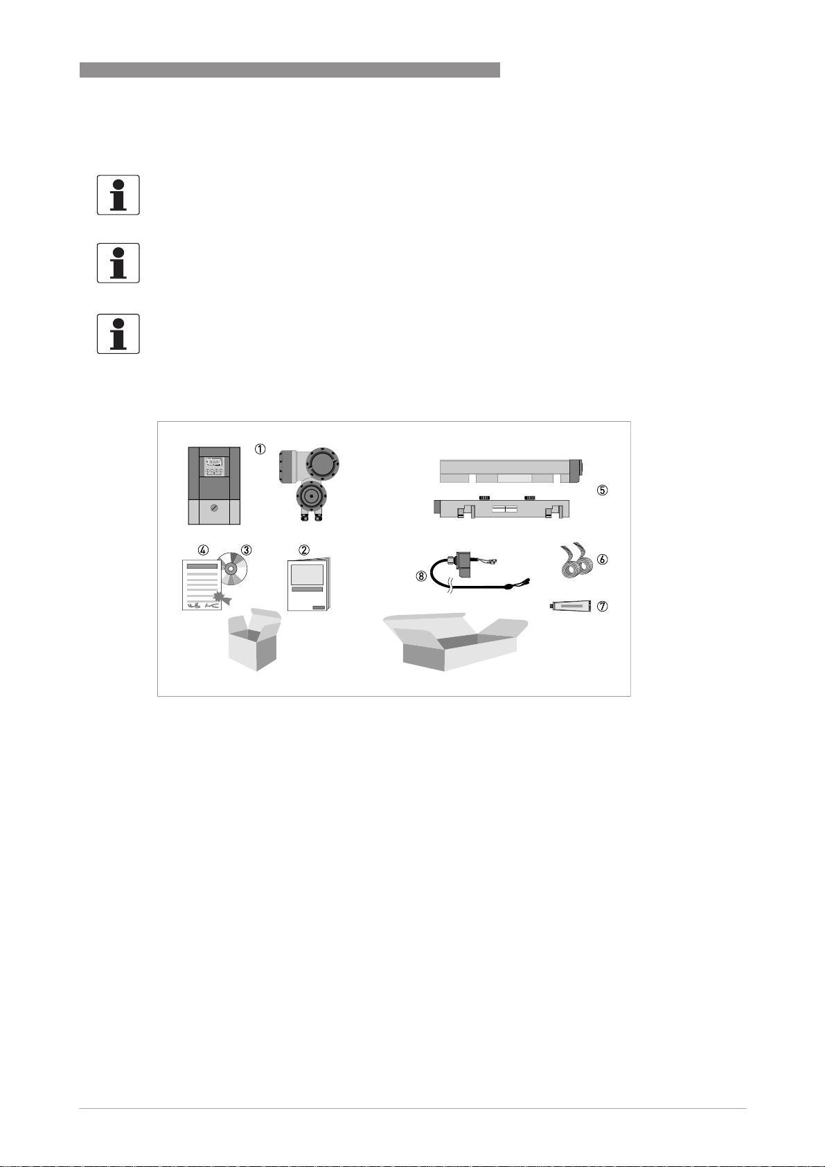
Figure 2-1: Scope of delivery
1 Signal converter, wall version or field version
2 Quick Start
3 CD-ROM (including Handbook, Quick Start, Technical Datasheet, Support database, movie)
4 Factory calibration report
5 Sensor plus cover (stainless steel / XT version without cover)
6 Metal strap
7 Mineral coupling grease (standard versions) or high temperature contactgel Pyrogel
8 Signal cable plus connector cap (XT versions have a protection sleeve around the signal cable).
®
(XT versions)
www.krohne.com07/2009 - 4000263902 - HB OPTISONIC 6300 R03 en
11
Page 12
2 DEVICE DESCRIPTION
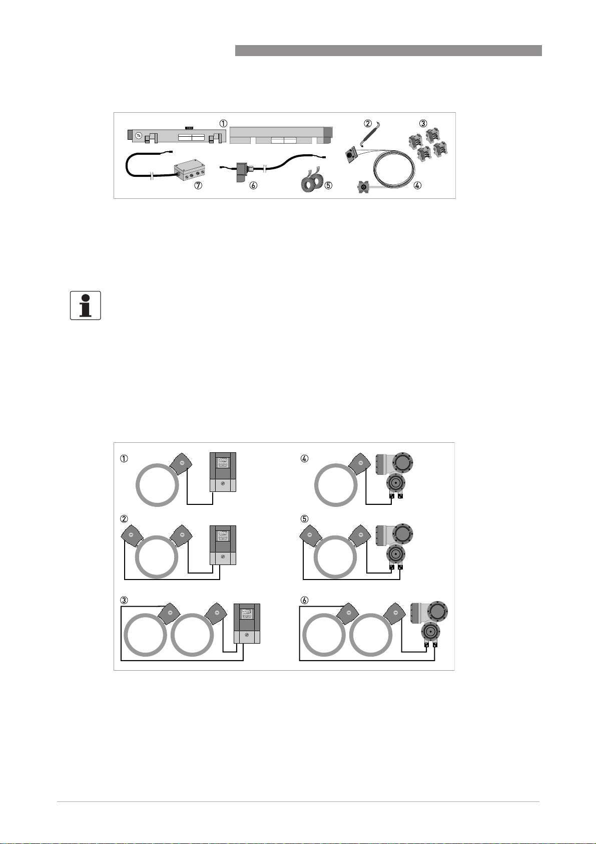
Additionally for large version:
1 2nd sensor plus cover
2 90 degree screw driver
3 4 fixing units
4 Positioning tool
5 2 metal straps
6 Signal cable plus connector cap
7 Cable box plus signal cable
INFORMATION!
No special tools, no training required!
OPTISONIC 6300
2.2 Device description
The ultrasonic clamp-on flowmeter can be fitted on the outside of piping to measure the flow
rate of liquids.
The device is a combination of one up to two clamp-on sensor(s) and one ultrasonic flow
converter.
12
Figure 2-2: System configuration possibilities
www.krohne.com 07/2009 - 4000263902 - HB OPTISONIC 6300 R03 en
Page 13
OPTISONIC 6300
The underneath accessories can be ordered optionally:
• GDC interface set
• SoundCheck
• Coupling grease; mineral (standard versions)
• High temperature contact gel Pyrogel
2.3 Nameplates
INFORMATION!
Look at the device nameplate to ensure that the device is delivered according to your order.
Check for the correct supply voltage printed on the nameplate.
2.3.1 Overview
®
(XT versions)
DEVICE DESCRIPTION 2
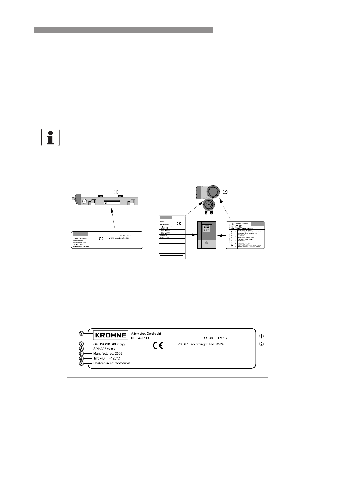
Figure 2-3: Visual check
1 Flow sensor
2 Signal converter
2.3.2 Flow sensor
Figure 2-4: Nameplate flow sensor
1 Ambient temperature operating range
2 Protection category
3 Calibration number
4 Process temperature (-40...+200°C for XT version)
5 Manufacturing year
6 Serial number
7 Device type (yyy = small, medium or large)
8 Manufacturer
www.krohne.com07/2009 - 4000263902 - HB OPTISONIC 6300 R03 en
13
Page 14
2 DEVICE DESCRIPTION
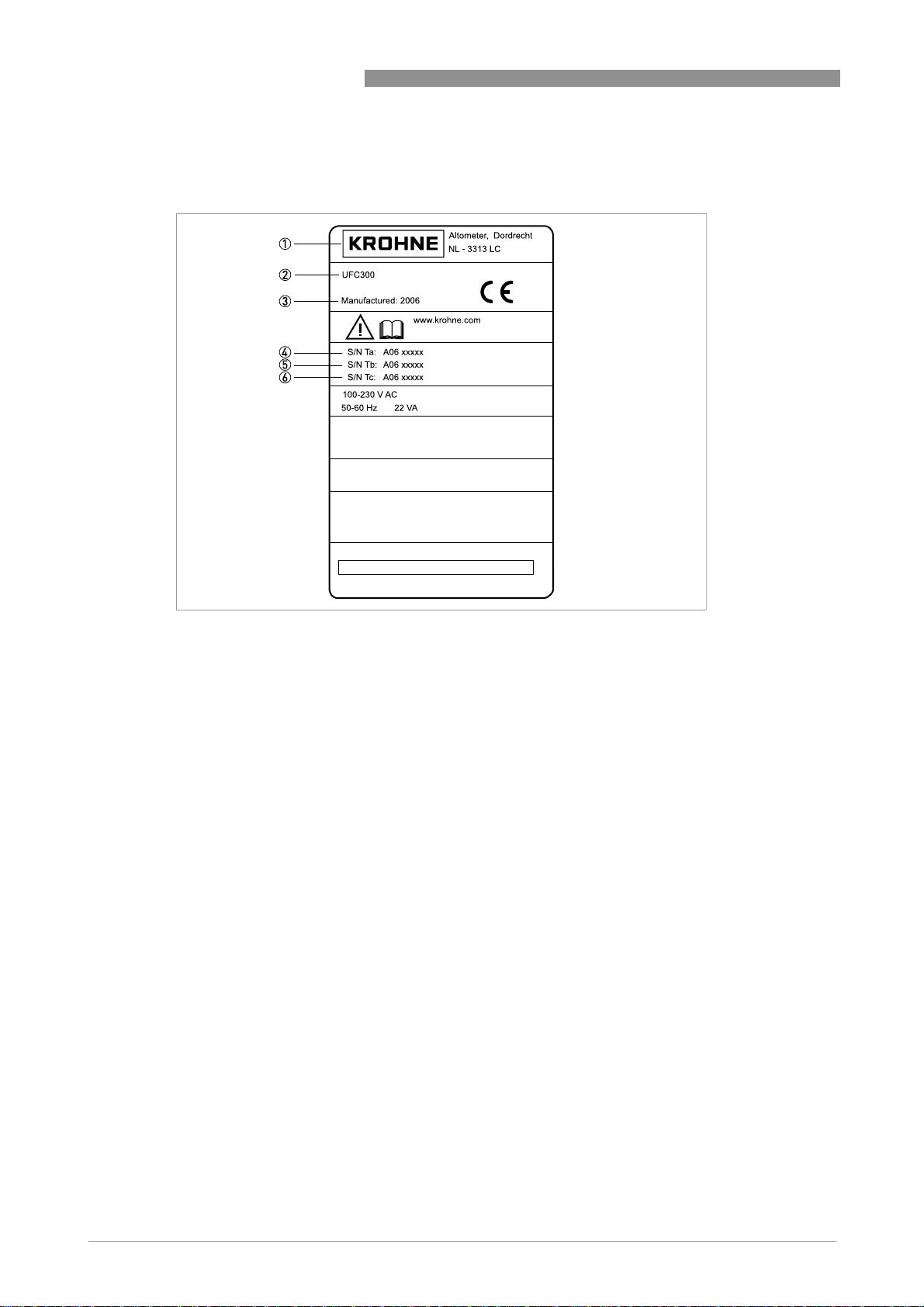
2.3.3 Signal converter
OPTISONIC 6300
Figure 2-5: Nameplate
1 Manufacturer
2 Device type
3 Manufacturing year
4 Serial number sensor 1 + short code flow sensor
5 Serial number sensor 2 + short code flow sensor
6 Empty
14
www.krohne.com 07/2009 - 4000263902 - HB OPTISONIC 6300 R03 en
Page 15
OPTISONIC 6300
DEVICE DESCRIPTION 2
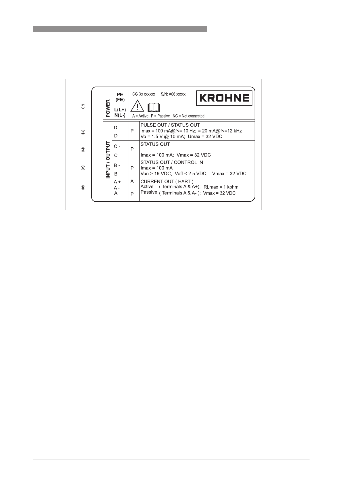
2.3.4 Electrical connection data of inputs/outputs (example of basic version)
Figure 2-6: Example of a nameplate for electrical connection data of inputs and outputs
1 Power supply (AC: L and N; DC: L+ and L-; PE for ≥ 24 VAC; FE for ≤ 24 VAC and DC)
2 Connection data of connection terminal D/D-
3 Connection data of connection terminal C/C-
4 Connection data of connection terminal B/B-
5 Connection data of connection terminal A/A-; A+ only operable in the basic version
• A = active mode; the signal converter supplies the power for connection of the subsequent
devices
• P = passive mode; external power supply required for operation of the subsequent devices
• N/C = connection terminals not connected
www.krohne.com07/2009 - 4000263902 - HB OPTISONIC 6300 R03 en
15
Page 16

3 INSTALLATION
3.1 Notes on installation
INFORMATION!
Inspect the cartons carefully for damage or signs of rough handling. Report damage to the
carrier and to the local office of the manufacturer.
INFORMATION!
Check the packing list to check if you received completely all that you ordered.
INFORMATION!
Look at the device nameplate to ensure that the device is delivered according to your order.
Check for the correct supply voltage printed on the nameplate.
3.2 Storage
• Store the flowmeter in a dry and dust-free location.
• Avoid lasting direct exposure to the sun.
• Store the flowmeter in its original packing.
OPTISONIC 6300
3.3 Transport
No special requirements.
3.4 Pre-installation requirements
INFORMATION!
To assure a quick, safe and uncomplicated installation, we kindly request you to make provisions
as stated below.
3.4.1 Environmental requirements
• Pollution degree 2
• Protection class I
• Humidity: 5...80 % RH
• Temperature: –40…+60°C / -40…+140°F operating and –50…+70°C / -58…+158°F storage
• Suitable for indoor and outdoor use and certified for operating up to an altitude of
2000 m / 6562 ft
• IP class 66/67
CAUTION!
The device should be protected from corrosive chemicals or gases and dust / particles
accumulation.
16
www.krohne.com 07/2009 - 4000263902 - HB OPTISONIC 6300 R03 en
Page 17
OPTISONIC 6300
3.4.2 Installation requirements signal converter
• Allow 10…20 cm / 3.9…7.9" of space at the sides and rear of the signal converter to permit
free air circulation.
• Protect signal converter against direct solar radiation, install a sunshield if necessary.
• Signal converters installed in switchgear cabinets require adequate cooling, e.g. by fan or
heat exchanger.
• Do not expose the signal converter to intense vibration.
INFORMATION!
For detailed information please also refer to Housing on page 115
3.5 Installation requirements sensor
INFORMATION!
To avoid measuring errors and malfunctioning of the flowmeter due to gas or air inclusions or an
empty pipe, please observe the following precautions.
INSTALLATION 3
.
CAUTION!
Since gas will collect at the highest point of a pipe, installation of the flowmeter at that location
should be avoided at all times. Also installation in a down going pipe should be avoided since a
completely filled pipe may not be guaranteed due to cascading effects. Additionally flow profile
distortion is possible.
CAUTION!
If you program the diameter, please note that you use the outer diameter of the pipe.
www.krohne.com07/2009 - 4000263902 - HB OPTISONIC 6300 R03 en
17
Page 18
3 INSTALLATION
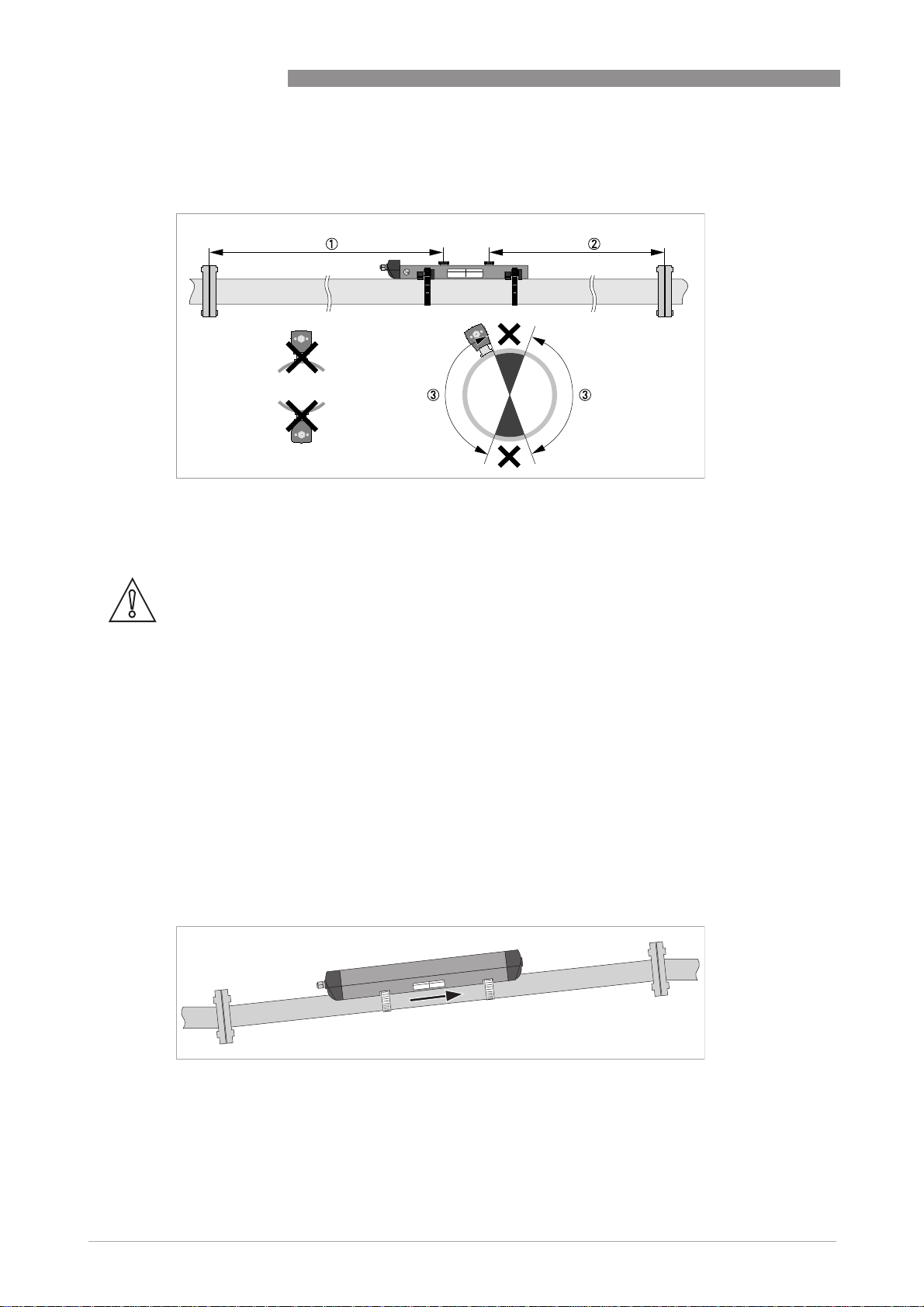
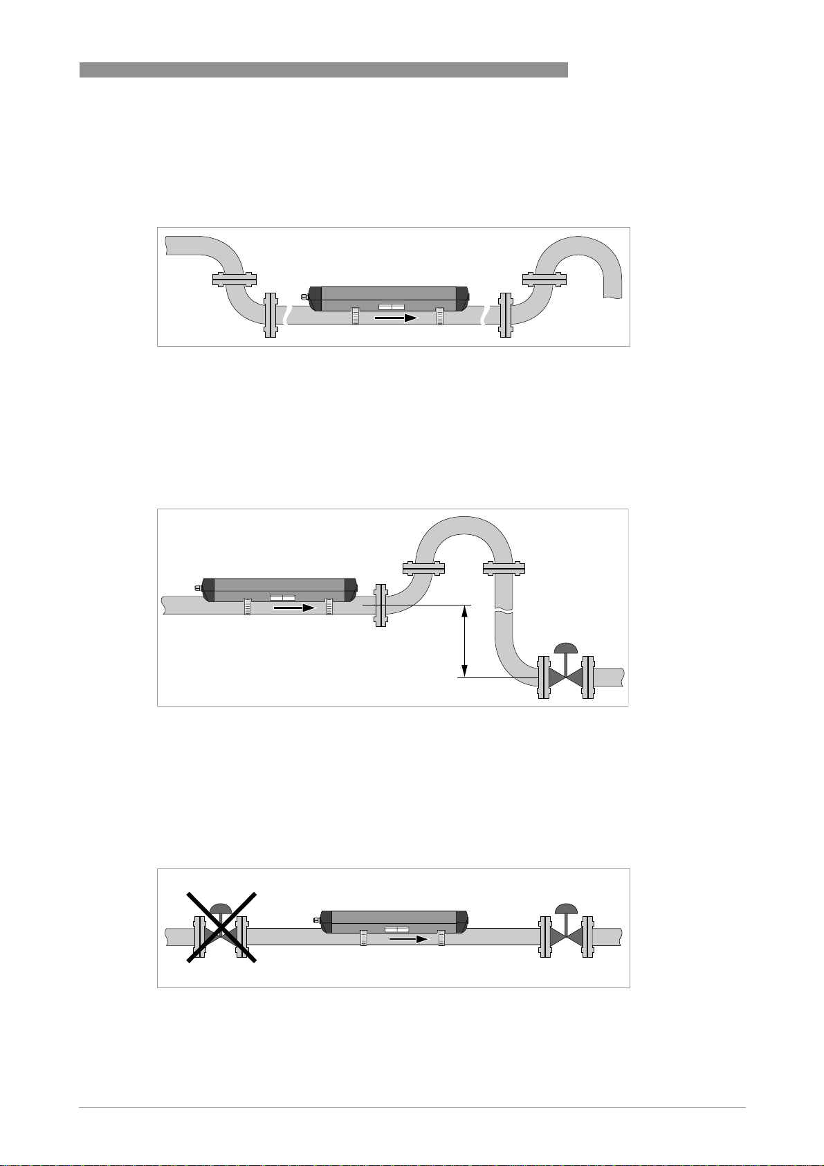
3.5.1 Inlet, outlet and recommended mounting area
Figure 3-1: Inlet, outlet and recommended mounting area
1 Min. 10 DN
2 Min. 5 DN
3 OK, 120°
OPTISONIC 6300
CAUTION!
Especially for XT (eXtended Temperature) versions:
•
Always install the sensor at a non-insulated part of the pipe. Remove any insulation if
necessary!
•
Bend radius of cable plus connection box needs 10 cm / 4" additional non insulated pipe
section.
•
Always wear protections gloves.
3.5.2 Long horizontal pipes
• Install on slightly ascending pipe section.
• If not possible, ensure adequate velocity to prevent air, gas or vapor from collecting in upper
part.
• In partially filled pipes, the clamp-on flowmeter will report incorrect flow rates, or not
measure.
18
Figure 3-2: Long horizontal pipes
www.krohne.com 07/2009 - 4000263902 - HB OPTISONIC 6300 R03 en
Page 19
OPTISONIC 6300
3.5.3 Open feed or discharge
Install meter on a lowered section of the pipe to ensure a full pipe condition through the meter.
Figure 3-3: Open feed or discharge
3.5.4 Down going pipeline over 5 m /16 ft length
Install air vent downstream of the flow meter to prevent vacuum. Although this will not harm the
meter, it may cause gases to come out of solution (cavitate) and interfere with proper
measurements.
INSTALLATION 3
Figure 3-4: Down going pipeline over 5 m /16 ft length
3.5.5 Position of control valve
Always install control valves downstream of flowmeter in order to avoid cavitation or distortion
of flow profile.
Figure 3-5: Position of control valve
www.krohne.com07/2009 - 4000263902 - HB OPTISONIC 6300 R03 en
19
Page 20
3 INSTALLATION
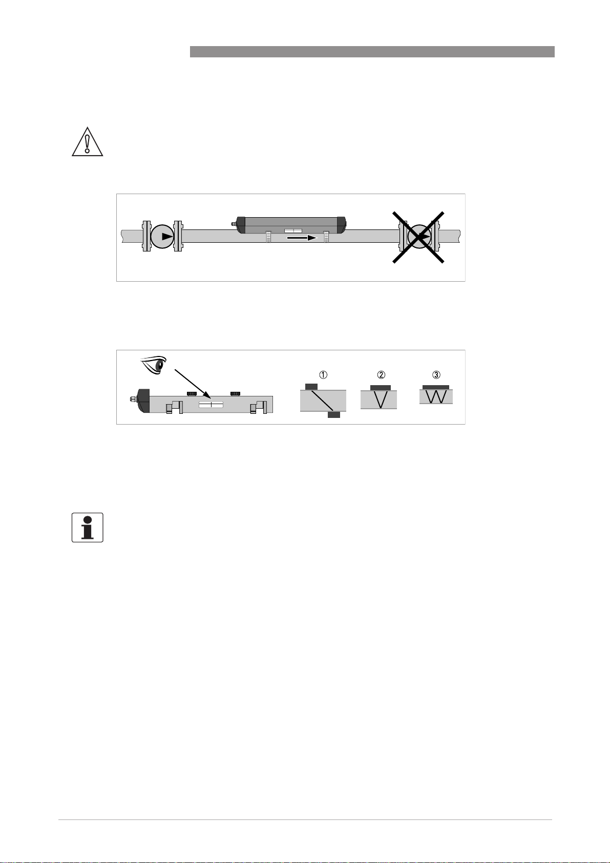
3.5.6 Position of pump
CAUTION!
Never install flowmeter at a pump suction side in order to avoid cavitation or flashing in the
flowmeter.
Figure 3-6: Position of pump
3.5.7 Pipe diameters and sensor construction
OPTISONIC 6300
Figure 3-7: Measuring modes
1 Z-mode
2 V-mode
3 W-mode
3.5.8 Pipe and media parameters
INFORMATION!
Detailed databases of most pipe and media parameters are on the supplied CD.
20
www.krohne.com 07/2009 - 4000263902 - HB OPTISONIC 6300 R03 en
Page 21
OPTISONIC 6300
3.6 Installation of the flowmeter
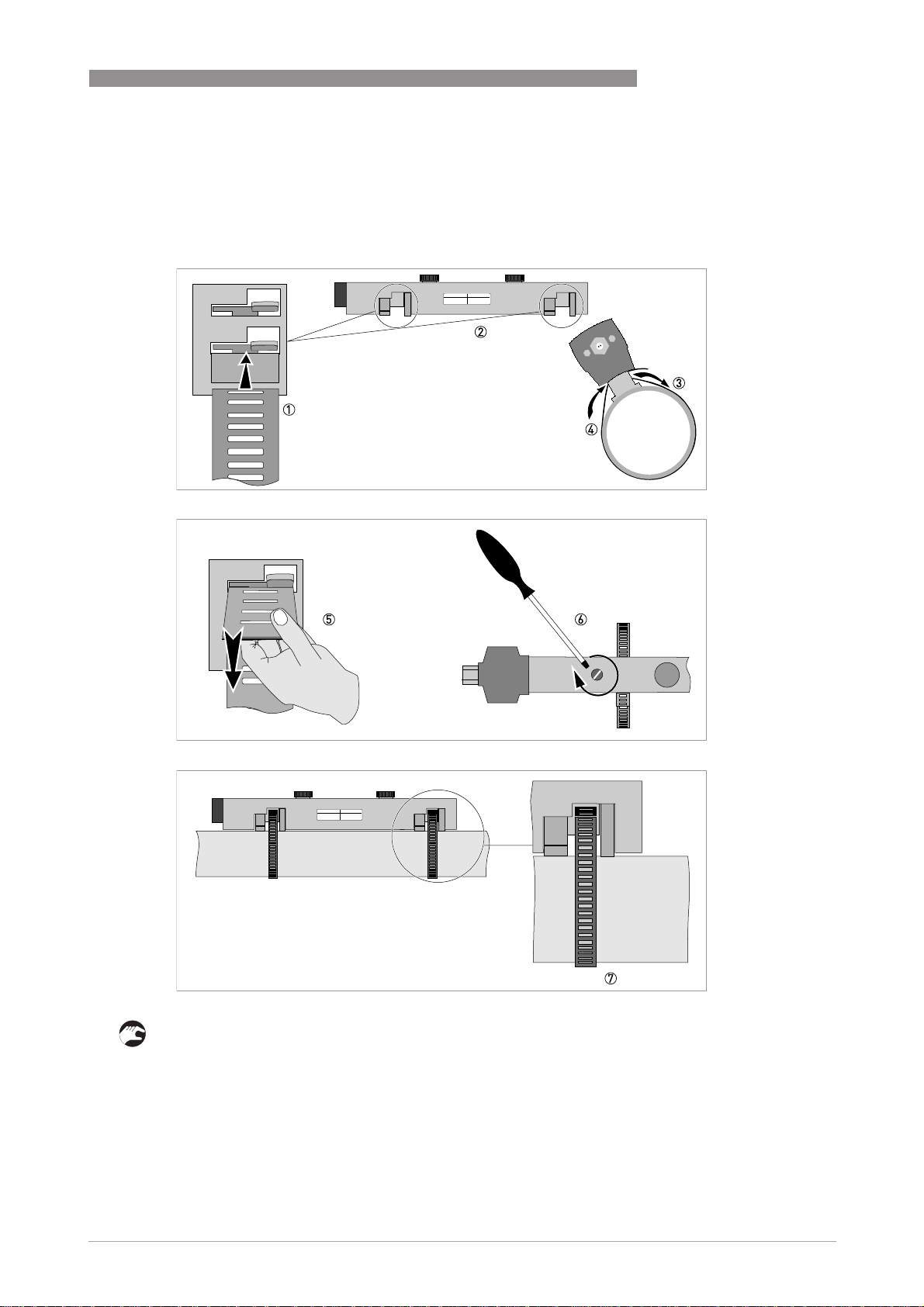
3.6.1 General mechanical installation
Installation of the rails with the metal straps
Installation of the rails with the metal straps
Installation of the rails with the metal strapsInstallation of the rails with the metal straps
INSTALLATION 3
• 8: Repeat steps 1...7 at the other side of the rail.
www.krohne.com07/2009 - 4000263902 - HB OPTISONIC 6300 R03 en
21
Page 22
3 INSTALLATION
Change the position of the transducer
Change the position of the transducer
Change the position of the transducerChange the position of the transducer
• Unlock the floating transducer 2 by turning the locking knob 1 counter clockwise.
• Slide the transducer 2 to the advised mounting distance 3 (menu X9.4).
• Lock the transducer by turning the locking knob 1 clockwise.
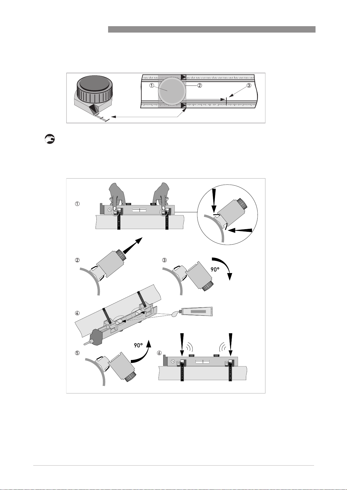
Greasing the transducer surfaces
Greasing the transducer surfaces
Greasing the transducer surfacesGreasing the transducer surfaces
OPTISONIC 6300
22
www.krohne.com 07/2009 - 4000263902 - HB OPTISONIC 6300 R03 en
Page 23
OPTISONIC 6300
INFORMATION!
Not applicable for stainless steel / XT versions. These are delivered without cover.
Mounting the cover
Mounting the cover
Mounting the coverMounting the cover
INSTALLATION 3
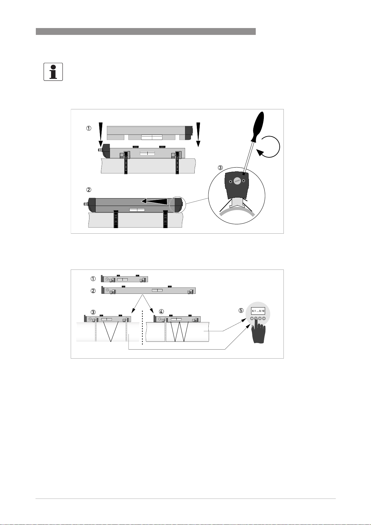
3.6.2 Installation instructions for small and medium version
Figure 3-8: Procedure for installation of small or medium version
1 Rail, small version
2 Rail, medium version
3 Choose for V-mode or ...
4 Choose for W-mode
5 Make settings in converter
www.krohne.com07/2009 - 4000263902 - HB OPTISONIC 6300 R03 en
23
Page 24
3 INSTALLATION
OPTISONIC 6300
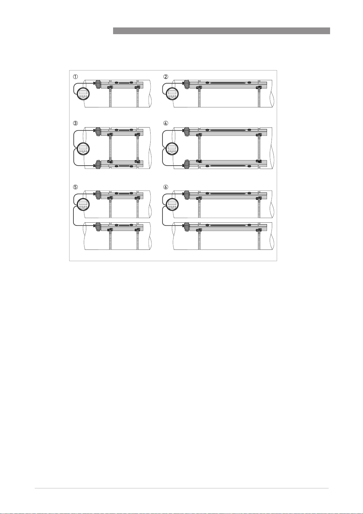
Figure 3-9: Device versions
1 Small version: single pipe / single path
2 Medium version: single pipe / single path
3 Small version: single pipe / dual path
4 Medium version: single pipe / dual path
5 Small version: dual pipe / single path
6 Medium version: dual pipe / single path
24
www.krohne.com 07/2009 - 4000263902 - HB OPTISONIC 6300 R03 en
Page 25
OPTISONIC 6300
3.6.3 Installation instructions for large version
INSTALLATION 3
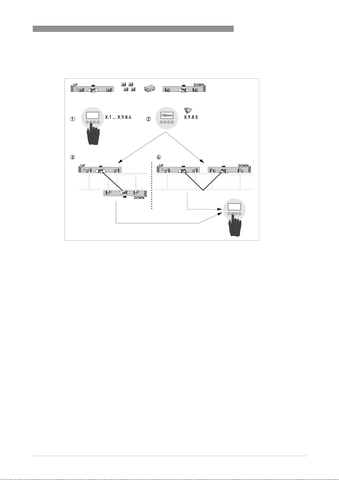
Figure 3-10: Procedure for installation of large version
1 Enter the values for the installation menu, X1...X9.8.4
2 Read the advised mounting distance in menu X9.8.5
3 Choose for Z-mode (default) or ...
4 Choose for V-mode
5 Finish the installation menu
www.krohne.com07/2009 - 4000263902 - HB OPTISONIC 6300 R03 en
25
Page 26
3 INSTALLATION
OPTISONIC 6300
Figure 3-11: Device versions
1 Single pipe, single path
2 Single pipe, dual path
3 Dual pipe
26
www.krohne.com 07/2009 - 4000263902 - HB OPTISONIC 6300 R03 en
Page 27
OPTISONIC 6300
3.7 Mounting of converter
CAUTION!
Always use the supplied signal cable. Keep the distance between the sensor and the signal
converter as short as possible.
3.7.1 Mounting of UFC 300 F
Perform the following procedures:
• Mount converter with mounting plate on wall or standpipe.
• Observe maximum allowed length of 30 m / 98.4 ft for the signal cable
3.7.2 Turning the display of the field housing version
INSTALLATION 3
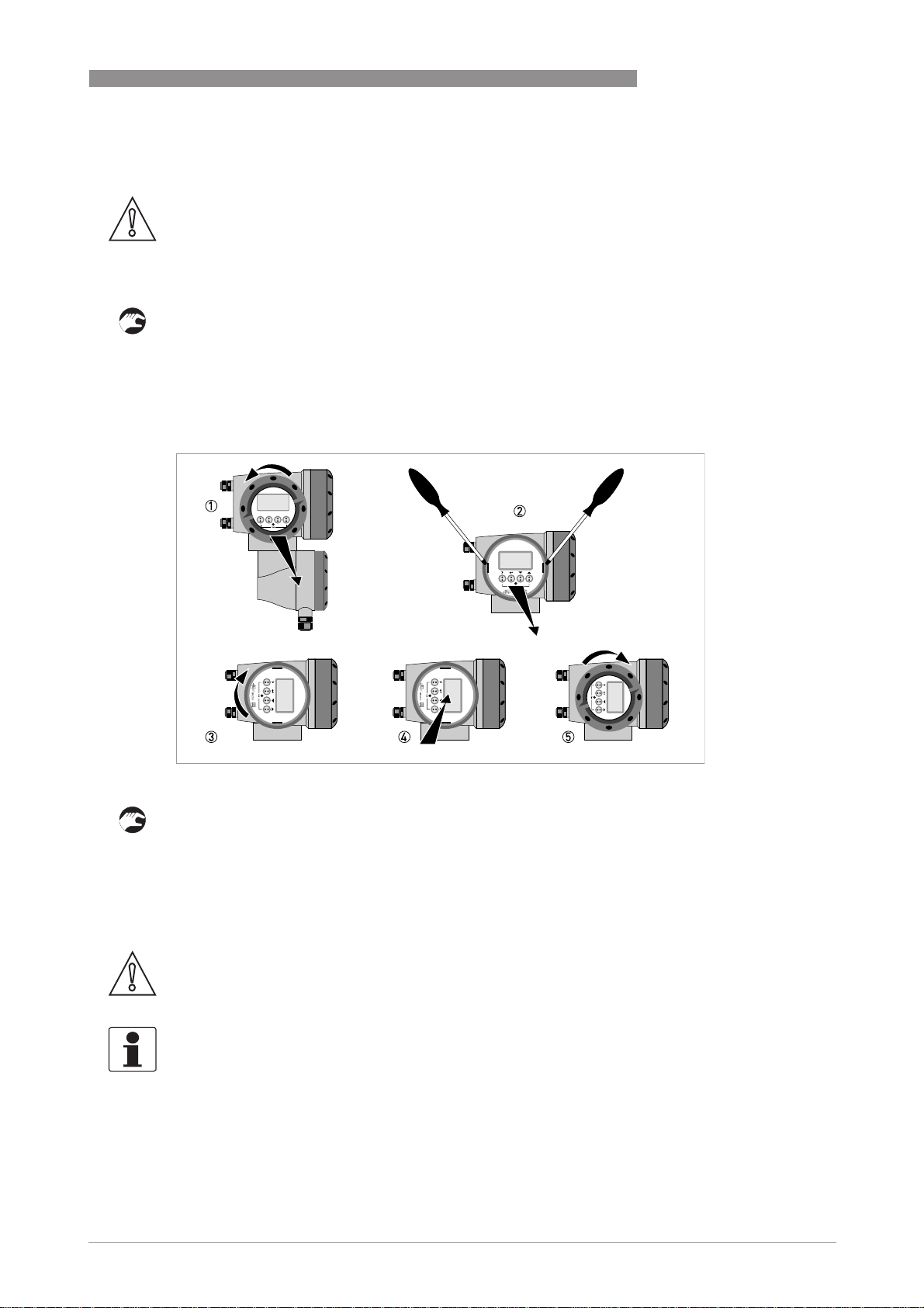
Figure 3-12: Turning the display of the field housing version
The display of the field housing version can be turned in 90° increments.
1 Unscrew the cover from the display and operation control unit.
2 Using a suitable tool, pull out the two metal puller devices to the left and right of the display.
3 Pull out the display between the two metal puller devices and rotate it to the required position.
4 Slide the display and then the metal puller devices back into the housing.
5 Re-fit the cover and tighten it by hand.
CAUTION!
The ribbon cable of the display must not be folded or twisted repeatedly.
INFORMATION!
Each time a housing cover is opened, the thread should be cleaned and greased. Use only resinfree and acid-free grease.
Ensure that the housing gasket is properly fitted, clean and undamaged.
www.krohne.com07/2009 - 4000263902 - HB OPTISONIC 6300 R03 en
27
Page 28

3 INSTALLATION
3.7.3 Mounting of UFC 300 W
Perform the following procedures:
• Remove aluminium mounting plate from rear of the signal converter, and attach to wall or
standpipe.
• Mount signal converter.
• Position lock washers and nuts on the housing bolts, tighten nuts slightly.
• Align housing, tighten nuts firmly.
• Observe max. allowed length of 30 m / 98.4 ft for the signal cable.
OPTISONIC 6300
28
www.krohne.com 07/2009 - 4000263902 - HB OPTISONIC 6300 R03 en
Page 29
OPTISONIC 6300
4.1 Safety instructions
DANGER!
All work on the electrical connections may only be carried out with the power disconnected. Take
note of the voltage data on the nameplate!
DANGER!
Observe the national regulations for electrical installations!
DANGER!
For devices used in hazardous areas, additional safety notes apply; please refer to the Ex
documentation.
WARNING!
Observe without fail the local occupational health and safety regulations. Any work done on the
electrical components of the measuring device may only be carried out by properly trained
specialists.
ELECTRICAL CONNECTIONS 4
INFORMATION!
Look at the device nameplate to ensure that the device is delivered according to your order.
Check for the correct supply voltage printed on the nameplate.
4.2 Construction of the various housing versions
4.2.1 UFC 300 F
The terminal compartments are accessible after unscrewing cover 2 and 6.
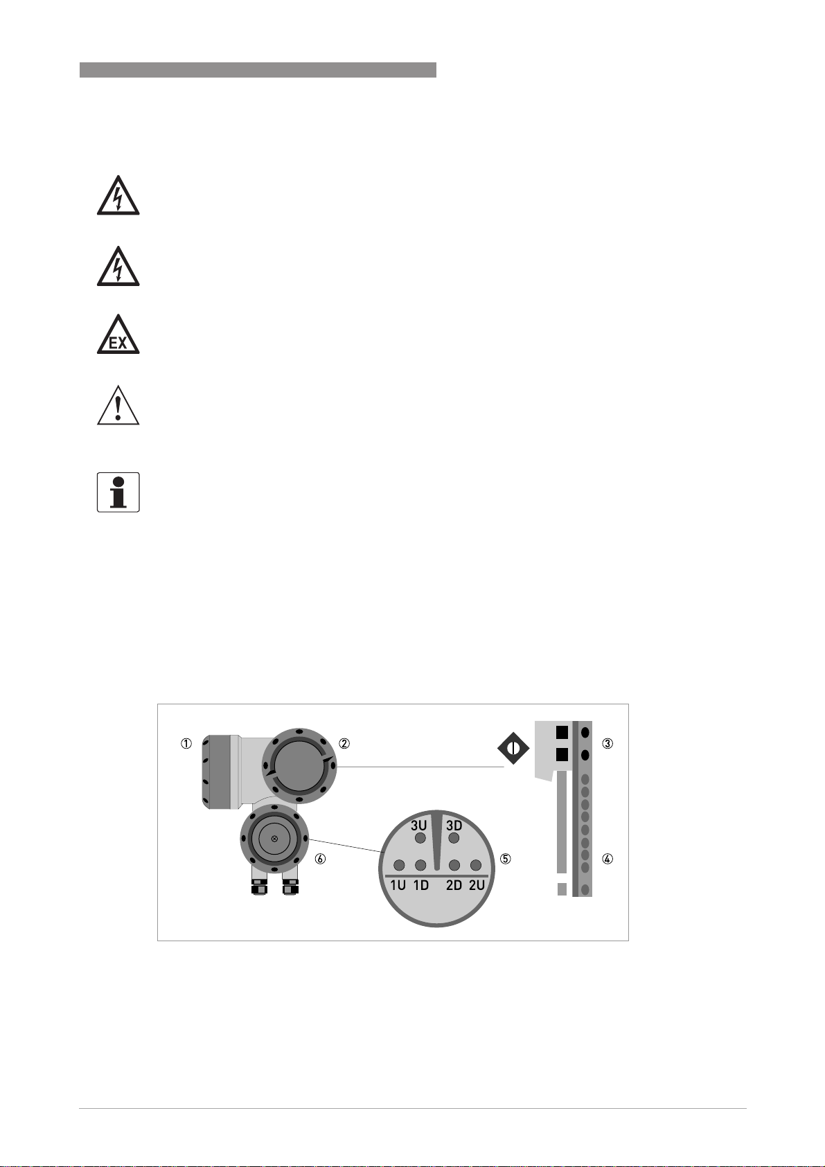
Figure 4-1: Construction (field version)
1 Cover, electronics compartment
2 Cover, terminal compartment for power supply and inputs/outputs
3 Cable entry for power
4 Cable entry for inputs/outputs
5 Cable entry for sensor cable
6 Cover, sensor terminal compartment
www.krohne.com07/2009 - 4000263902 - HB OPTISONIC 6300 R03 en
29
Page 30
4 ELECTRICAL CONNECTIONS
4.2.2 UFC 300 W
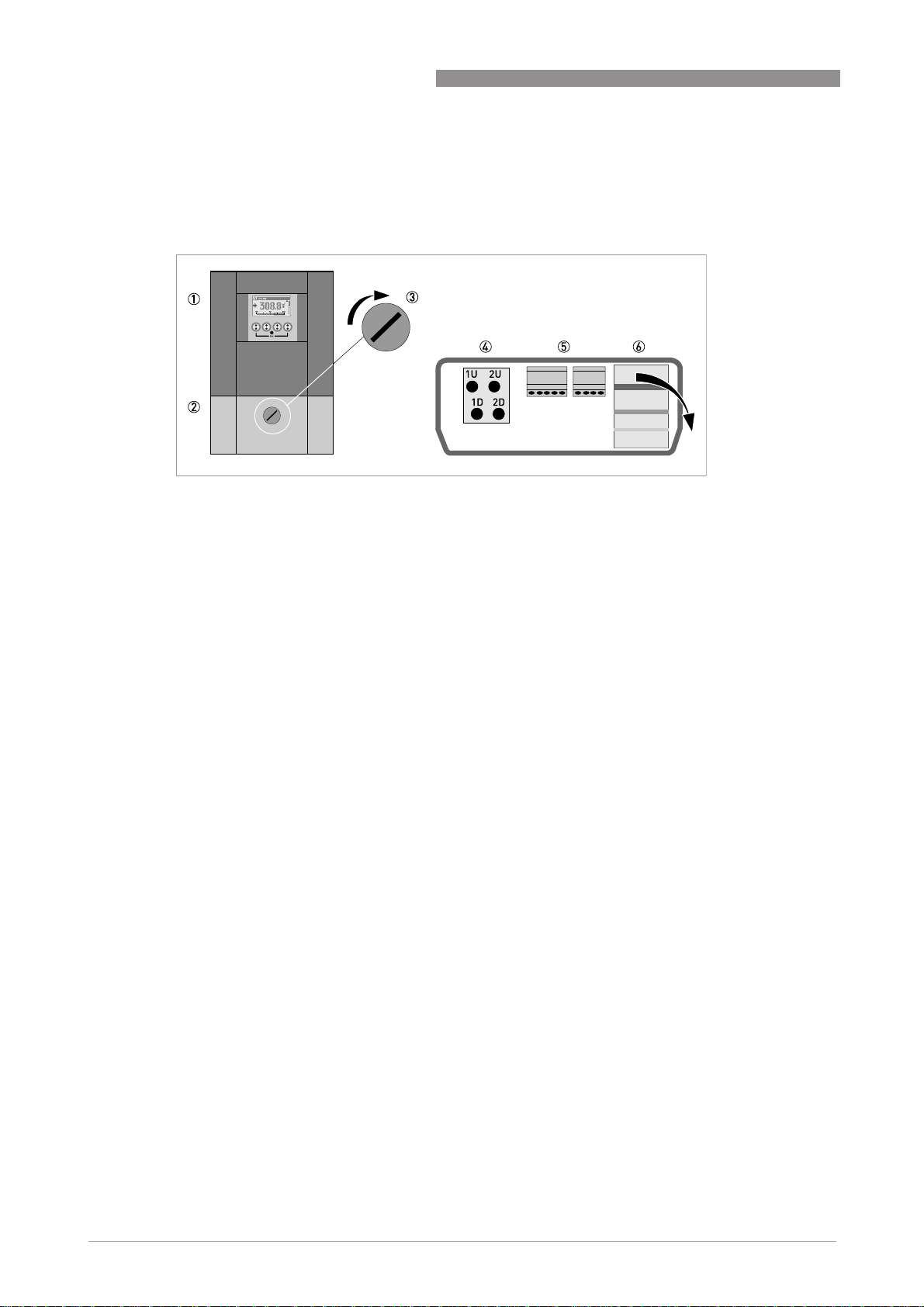
The terminal compartments are accessible after opening cover 2.
Figure 4-2: Construction of remote version
1 Cover, electronics compartment
2 Cover for the three separate terminal compartments for power, sensor connection and inputs/outputs
3 Locking screw, 1/2 turn left/right to open/close cover 2
4 Sensor terminal compartment
5 Terminal compartment for inputs/outputs
6 Power terminal compartment, open separate shock-hazard protection cover
OPTISONIC 6300
30
www.krohne.com 07/2009 - 4000263902 - HB OPTISONIC 6300 R03 en
Page 31

OPTISONIC 6300
4.3 Electrical connection
CAUTION!
To ensure smooth functioning, always use the signal cables included in the delivery.
The flow sensor is connected to the signal converter via the single signal cable.
4.3.1 Signal cable to flow sensor
Figure 4-3: Connecting the signal cable to the rail (small and medium version)
1 Connect the green cable to "DOWN"
2 Connect the blue cable to "UP"
3 Turn the screws clockwise to secure the cap
ELECTRICAL CONNECTIONS 4
Figure 4-4: Connect the signal cable in case of stainless steel / XT version.
1 Put in the connector.
2 Turn knob to secure the connector.
CAUTION!
For XT versions: check if the signal cable is heat protected with the protection sleeve of 1 meter /
40".
www.krohne.com07/2009 - 4000263902 - HB OPTISONIC 6300 R03 en
31
Page 32
4 ELECTRICAL CONNECTIONS
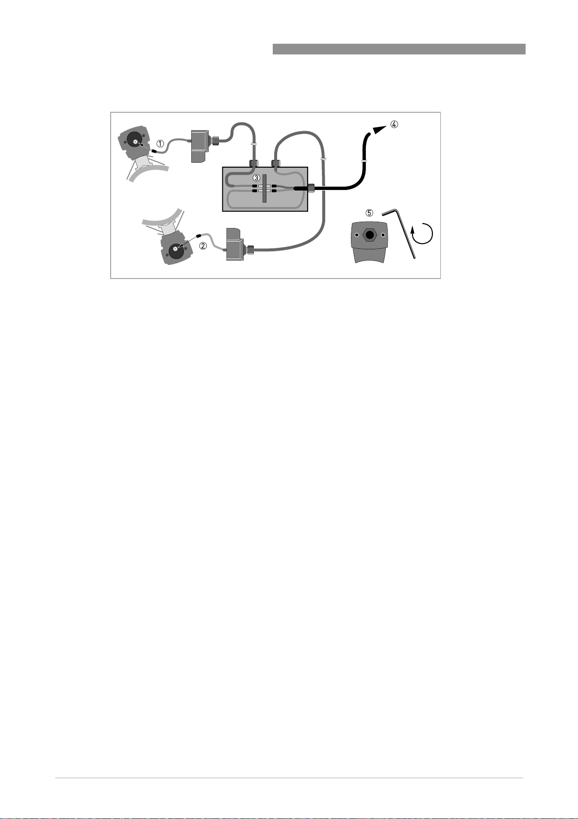
Figure 4-5: Connections in cable box (large version)
1 Connect the blue cable to the UP rail.
2 Connect the green cable to the DOWN rail.
3 Make connections in cable box.
4 Cable to converter
5 Turn the screws clockwise to secure the caps.
OPTISONIC 6300
32
www.krohne.com 07/2009 - 4000263902 - HB OPTISONIC 6300 R03 en
Page 33

OPTISONIC 6300
ELECTRICAL CONNECTIONS 4
4.3.2 Signal cable and power supply signal converter
INFORMATION!
The power terminals in the terminal compartments are equipped with additional hinged lids to
prevent accidental contact.
DANGER!
The device must be grounded in accordance with regulations in order to protect personnel
against electric shocks.
Figure 4-6: Construction of wall version
1 Connect blue cable to 1U (to 2U for 2
2 Communication I/O
3 Power supply: 24 VAC/DC or 100...240 VAC
nd
sensor) and the green cable to 1D (2D for 2nd sensor)
www.krohne.com07/2009 - 4000263902 - HB OPTISONIC 6300 R03 en
33
Page 34

4 ELECTRICAL CONNECTIONS
Figure 4-7: Construction (field version)
1 Cover, electronics compartment
2 Cover, terminal compartment for power supply and inputs/outputs
3 Cable entry for power
4 Cable entry for inputs/outputs
5 Cable entry for sensor cable
6 Cover, sensor terminal compartment
OPTISONIC 6300
100…230 VAC (-15% / +10%)
• Connect the protective ground conductor PE of the mains power supply to the separate
terminal in the terminal compartment of the signal converter.
• Connect the live conductor to the L terminal and the neutral conductor to the N terminal.
24 VAC/DC (-15% / +10%)
• For reasons to do with the measurement process, connect a functional ground FE to the
separate U-clamp terminal in the terminal compartment of the signal converter.
• When connecting to functional extra-low voltages, provide a facility for protective separation
(PELV) (VDE 0100 / VDE 0106 and/or IEC 364 / IEC 536 or relevant national regulations).
34
www.krohne.com 07/2009 - 4000263902 - HB OPTISONIC 6300 R03 en
Page 35

OPTISONIC 6300
4.3.3 Laying electrical cables correctly
Figure 4-8: Protect housing from dust and water
1 Lay the cable in a loop just before the housing.
2 Tighten the screw connection of the cable entry securely.
3 Never mount the housing with the cable entries facing upwards.
4 Seal cable entries that are not needed with a plug.
ELECTRICAL CONNECTIONS 4
www.krohne.com07/2009 - 4000263902 - HB OPTISONIC 6300 R03 en
35
Page 36

4 ELECTRICAL CONNECTIONS
4.4 Description of the electrical symbols
mA meter
0...20 mA or 4...20 mA and other
RL is the internal resistance of the measuring point including the cable
resistance
DC voltage source (U
OPTISONIC 6300
), external power supply, any connection polarity
ext
Table 4-1: Description of symbols
DC voltage source (U
connection diagrams
Internal DC voltage source
Controlled internal power source in the device
Electronic or electromagnetic counter
At frequencies above 100 Hz, shielded cables must be used to connect the
counters.
Ri Internal resistance of the counter
Button, NO contact or similar
), observe connection polarity according to
ext
36
www.krohne.com 07/2009 - 4000263902 - HB OPTISONIC 6300 R03 en
Page 37

OPTISONIC 6300
4.5 Basic inputs and outputs
The signal converter has several in / output ports, accessible via the terminal compartment for
interfacing with external devices. The terminal compartment is accessible after unscrewing the
cover.
ELECTRICAL CONNECTIONS 4
Figure 4-9: Field housing, I/O terminals
Figure 4-10: Wall housing, I/O terminals
The input / output ports are galvanic separated from each other and from all other input and
output circuits.
• Active I/O:
Active I/O: the UFC 300 signal converter supplies the power for operation
Active I/O:Active I/O:
• Passive I/O:
Passive I/O: an external power supply is required
Passive I/O:Passive I/O:
Basic I/O consisting of:
• 1 current output,
• 1 pulse output,
• 1 status output,
• 1 control input.
The pulse output can also be set as a status output. One of the status outputs can be set as a
control input.
www.krohne.com07/2009 - 4000263902 - HB OPTISONIC 6300 R03 en
37
Page 38

4 ELECTRICAL CONNECTIONS
4.5.1 Fixed, non-alterable input/output versions
This measuring transducer is available with various input/output combinations.
CG-No. Connection terminals
A+ A A- B B- C C- D D-
Basic input/output (I/O) standard
1 0 0
Ia + HART® active 1
Ip + HART® passive 1
EEx-i inputs/outputs (I/Os) option
2 0 0
3 0 0
2 1 0 Ia active PN / SNNAMUR
3 1 0 Ia active PN / SNNAMUR
2 2 0 Ip passive PN / SNNAMUR
3 2 0 Ip passive PN / SNNAMUR
1 function changed by reconnection
2 changeable
Sp / Cp passive 2 Sp passive Pp / Sp passive 2
passive 2
C
p
Cp passive 2
passive 2
C
p
Cp passive 2
Ia + HART® active
Ip + HART® passive
Ia + HART® active
Ip + HART® passive
Ia + HART® active
Ip + HART® passive
OPTISONIC 6300
PN / SN NAMUR 2
PN / SN NAMUR 2
PN / SN NAMUR 2
PN / SN NAMUR 2
PN / SNNAMUR 2
PN / SNNAMUR 2
• The grey boxes in the tables denote unassigned or unused connection terminals.
• Connection terminal A+ is only operable in the basic input/output version.
38
www.krohne.com 07/2009 - 4000263902 - HB OPTISONIC 6300 R03 en
Page 39

OPTISONIC 6300
ELECTRICAL CONNECTIONS 4
Description of abbreviations and CG identifier for possible optional modules
on terminals A and B
Abbreviation Identifier for CG No. Description
I
a
I
p
Pa / S
Pp / S
PN / S
C
a
C
p
C
N
a
p
N
A
B
Active current output (including HART = HART® capability)
Passive current output (including HART = HART® capability)
C Active pulse, frequency, status output or limit switch (changeable)
E Passive pulse, frequency, status output or limit switch (changeable)
F Passive pulse, frequency, status output or limit switch according to
NAMUR (changeable)
G Active control input
K Passive control input
H Active control input to NAMUR
Signal converter monitors cable breaks and short circuits as per EN
60947-5-6. Errors indicated on LCD display. Error messages possible via
status output.
IIn
IIn
a
p
P Active current input
R Passive current input
- 8 No additional module installed
- 0 No further module possible
www.krohne.com07/2009 - 4000263902 - HB OPTISONIC 6300 R03 en
39
Page 40

4 ELECTRICAL CONNECTIONS
4.5.2 Basic inputs/outputs
CAUTION!
Observe connection polarity.
Current output active (HART®), basic I/Os
• U
• I ≤ 22 mA
• R
= 24 VDC nominal
int,nom
≤ 1kΩ
L
OPTISONIC 6300
Figure 4-11: Current output active I
a
Current output passive (HART®), basic I/Os
• U
• U
• I ≤ 22 mA
• U
• R
Figure 4-12: Current output passive I
= 24 VDC nominal
int,nom
≤ 32 VDC
ext
≥ 1.8
0
≤ (U
L
ext-U0
)/I
max
p
40
www.krohne.com 07/2009 - 4000263902 - HB OPTISONIC 6300 R03 en
Page 41

OPTISONIC 6300
INFORMATION!
•
For frequencies above 100 Hz, shielded cables are to be used in order to reduce radiation
from electrical interferences (EMC).
•
Compact and field housing versions:
Compact and field housing versions: Shield connected via the cable terminals in the terminal
Compact and field housing versions:Compact and field housing versions:
compartment.
Wall-mounted version:
Wall-mounted version: Shield connected using 6.3 mm / 0.25" push-on connectors
Wall-mounted version: Wall-mounted version:
(insulation to DIN 46245) in the terminal compartment.
•
Any connection polarity.
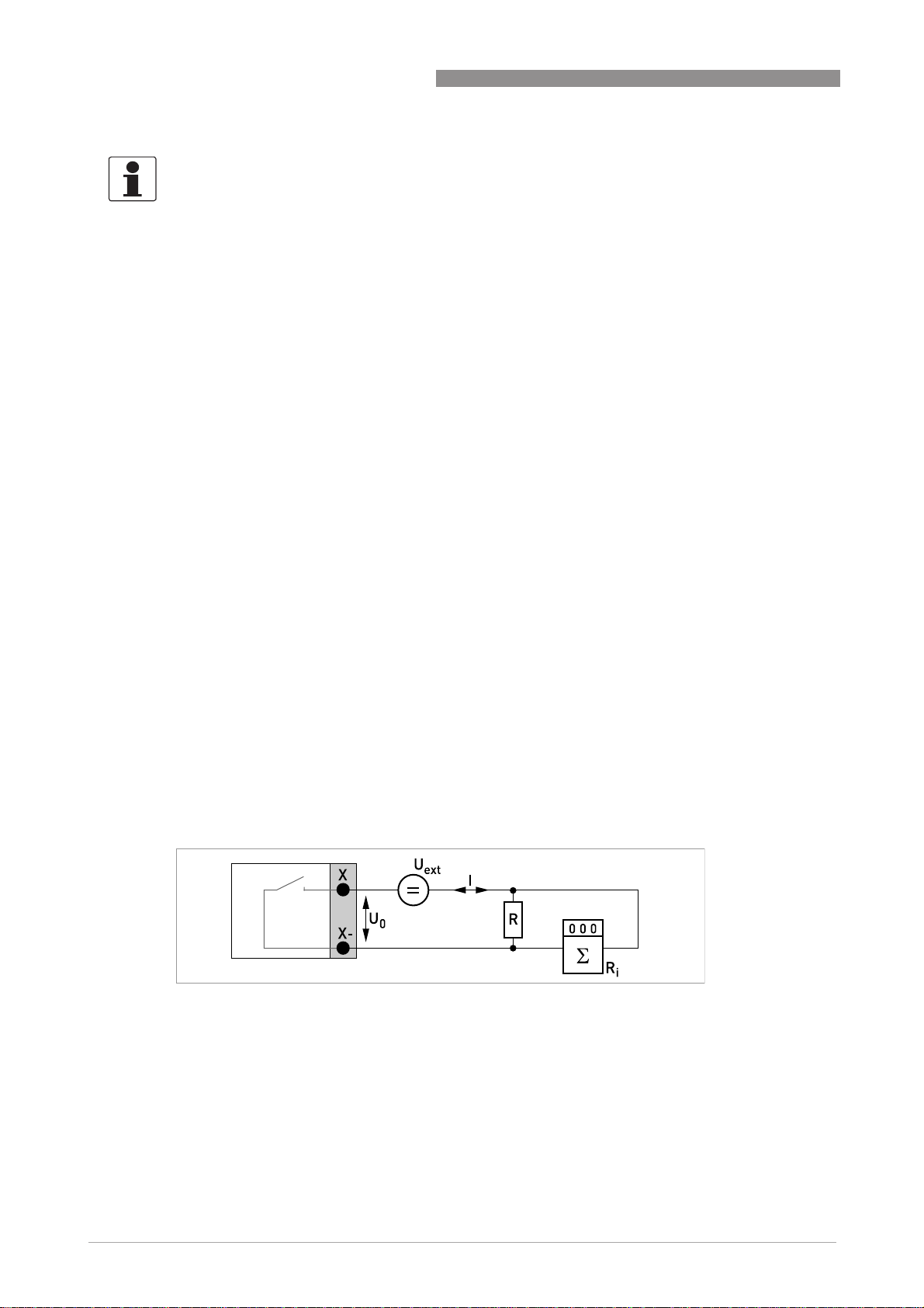
Pulse/frequency output passive, basic I/Os
• U
• f
I ≤ 100 mA
open:
I ≤ 0.05 mA at U
closed:
U
U
• f
I ≤ 20 mA
open:
I ≤ 0.05 mA at U
closed:
U
U
U
• If the following maximum load resistance R
reduced accordingly by parallel connection of R:
f ≤ 100 Hz: R
f ≤ 1 kHz: R
f ≤ 10 kHz: R
• The minimum load resistance R
R
• Can also be set as a status output; for the electrical connection, see status output connection
diagram.
≤ 32 VDC
ext
in operating menu set to f
max
= 32 VDC
ext
= 0.2 V at I ≤ 10 mA
0, max
= 2 V at I ≤ 100 mA
0, max
in the operating menu set to 100 Hz < f
max
= 32 VDC
ext
= 1.5 V at I ≤ 1 mA
0, max
= 2.5 V at I ≤ 10 mA
0, max
= 5.0 V at I ≤ 20 mA
0, max
= 47 kΩ
L, max
= 10 kΩ
L, max
= 1 kΩ
L, max
L, min
=(U
ext-U0
)/I
max
≤ 100 Hz:
max
L, min
ELECTRICAL CONNECTIONS 4
≤ 10 kHz:
max
is exceeded, the load resistance RL must be
L, max
is calculated as follows:
Figure 4-13: Pulse frequency output passive P
www.krohne.com07/2009 - 4000263902 - HB OPTISONIC 6300 R03 en
p
41
Page 42

4 ELECTRICAL CONNECTIONS
INFORMATION!
•
Any connection polarity.
Status output / limit switch passive, basic I/Os
• U
• I ≤ 100 mA
• R
• open:
• The output is open when the device is de-energized.
• X stands for the terminals B, C or D. The functions of the connection terminals depend on the
≤ 32 VDC
ext
= 47 kΩ
L, max
L, min
=(U
ext-U0
R
I ≤ 0.05 mA at U
closed:
U
U
= 0.2 V at I ≤ 10 mA
0, max
= 2 V at I ≤ 100 mA
0, max
settings.
)/I
= 32 VDC
ext
max
OPTISONIC 6300
Figure 4-14: Status output / limit switch passive S
p
Control input passive, basic I/Os
• 8V≤ U
• I
max
I
max
• Set switching point for detection "Contact open or closed:
Contact open (off): U
Contact closed (on): U
• Can also be set as a status output; for the electrical connection, see status output connection
diagram.
Figure 4-15: Control input passive C
1 Signal
≤ 32 VDC
ext
= 6.5 mA at U
= 8.2 mA at U
≤ 24 VDC
ext
≤ 32 VDC
ext
≤ 2.5 V with I
0
≥ 8 V with I
0
= 0.4 mA
nom
= 2.8 mA
nom
p
42
www.krohne.com 07/2009 - 4000263902 - HB OPTISONIC 6300 R03 en
Page 43

OPTISONIC 6300
4.5.3 HART® connection
INFORMATION!
•
In the basic I/O the current output at connection terminals A+/A-/A always has HART®
capability.
•
For modular I/O, only the current output module for the connection terminals has C/C-HART®
capability.
HART® connection active (point-to-point)
ELECTRICAL CONNECTIONS 4
Figure 4-16: HART® connection active (Ia)
1 Basic I/O: terminals A and A+
2 Modular I/O: terminals C- and C
3 HART
®
communicator
The parallel resistance to the HART® communicator must be R ≥ 230 Ω.
www.krohne.com07/2009 - 4000263902 - HB OPTISONIC 6300 R03 en
43
Page 44

4 ELECTRICAL CONNECTIONS
HART® connection passive (multidrop mode)
• I: I0% ≥ 4mA
• Multidrop mode I: I
• U
≤ 32 VDC
ext
• R ≥ 230 Ω
≥ 4mA = I
fix
0%
OPTISONIC 6300
Figure 4-17: HART® connection passive (Ip)
1 Basic I/O: terminals A- and A
2 Modular I/O: terminals C- and C
3 HART
4 Other HART
®
communicator
®
- capable devices
4.6 Modular Inputs and Outputs
INFORMATION!
In the following connection diagrams, the terminals A, B, C or D (depending on the version of the
UFC 300) are marked with a "X"
4.6.1 Alterable input/output versions
The signal converter is available with various input/output combinations.
CG-No. Connection terminals
A+ A A- B B- C C- D D-
Modular inputs/outputs option
4 _ _ max. 2 option modules for term. A + B
8 _ _ max. 2 option modules for term. A + B
6 _ _ max. 2 option modules for term. A + B
B _ _ max. 2 option modules for term. A + B
7 _ _ max. 2 option modules for term. A + B
"X".
"X""X"
Ia + HART® active
Ip + HART® passive
Ia + HART® active
Ip + HART® passive
Ia + HART® active
Pa / Sa active 1
Pa / Sa active 1
Pp / Sp passive 1
Pp / Sp passive 1
PN / SN NAMUR 1
44
www.krohne.com 07/2009 - 4000263902 - HB OPTISONIC 6300 R03 en
Page 45

OPTISONIC 6300
CG-No. Connection terminals
A+ A A- B B- C C- D D-
ELECTRICAL CONNECTIONS 4
C _ _ max. 2 option modules for term. A + B
1 changeable
Ip + HART® passive
Description of abbreviations and CG identifier for possible optional modules
on terminals A and B
Abbreviation Identifier for CG No. Description
I
a
I
p
Pa / S
a
Pp / S
p
PN / S
N
C
a
C
p
C
N
IIn
a
IIn
p
- 8 No additional module installed
- 0 No further module possible
A
B
Active current output (including HART = HART® capability)
Passive current output (including HART = HART® capability)
C Active pulse, frequency, status output or limit switch (changeable)
E Passive pulse, frequency, status output or limit switch (changeable)
F Passive pulse, frequency, status output or limit switch according to
NAMUR (changeable)
G Active control input
K Passive control input
H Active control input to NAMUR
Signal converter monitors cable breaks and short circuits as per EN
60947-5-6. Errors indicated on LCD display. Error messages possible via
status output.
P Active current input
R Passive current input
PN / SN NAMUR 1
www.krohne.com07/2009 - 4000263902 - HB OPTISONIC 6300 R03 en
45
Page 46

4 ELECTRICAL CONNECTIONS
4.6.2 Modular inputs/outputs and bus systems
CAUTION!
Observe connection polarity.
INFORMATION!
•
For the electrical connection of the bus systems, please refer to the separate documentation
for the respective bus systems.
Current output active (only current output terminals C/C- have HART® capability),
modular I/Os
• U
• I ≤ 22 mA
• R
• X designates the connection terminals A, B or C, depending on the version of the signal
converter.
int, nom
≤ 1kΩ
L
= 24 VDC
OPTISONIC 6300
Figure 4-18: Current output active I
a
Current output passive (only current output terminals C/C- have HART® capability),
modular I/Os
• U
• I ≤ 22 mA
• U
• R
• X designates the connection terminals A, B or C, depending on the version of the signal
Figure 4-19: Current output passive I
≤ 32 VDC
ext
≥ 1.8 V
0
≤ (U
L
ext-U0
converter.
)/I
max
p
46
www.krohne.com 07/2009 - 4000263902 - HB OPTISONIC 6300 R03 en
Page 47

OPTISONIC 6300
INFORMATION!
•
For frequencies above 100 Hz, shielded cables are to be used in order to reduce radiation
from electrical interferences (EMC).
•
Compact and field housing versions:
Compact and field housing versions: Shield connected via the cable terminals in the terminal
Compact and field housing versions:Compact and field housing versions:
compartment.
Wall-mounted version:
Wall-mounted version: Shield connected using 6.3 mm / 0.25" push-on connectors
Wall-mounted version: Wall-mounted version:
(insulation to DIN 46245) in the terminal compartment.
•
Any connection polarity.
Pulse/frequency output active, modular I/Os
• U
• f
I ≤ 20 mA
open:
I ≤ 0.05 mA
closed:
U
• f
I ≤ 20 mA
open:
I ≤ 0.05 mA
closed:
U
U
U
• If the following maximum load resistance R
reduced accordingly by parallel connection of R:
f ≤ 100 Hz: R
f ≤ 1 kHz: R
f ≤ 10 kHz: R
• The minimum load resistance R
R
• X designates the connection terminals A, B or D, depending on the version of the signal
converter.
= 24 VDC
nom
in operating menu set to f
max
= 24 V at I = 20 mA
0,nom
in the operating menu set to 100 Hz < f
max
= 22.5 V at I = 1 mA
0, nom
= 21.5 V at I = 10 mA
0, nom
= 19 V at I = 20 mA
0, nom
= 47 kΩ
L, max
= 10 kΩ
L, max
= 1 kΩ
L, max
L, min
=(U
ext-U0
)/I
max
≤ 100 Hz:
max
L, min
ELECTRICAL CONNECTIONS 4
≤ 10 kHz:
max
is exceeded, the load resistance RL must be
L, max
is calculated as follows:
Figure 4-20: Pulse / frequency output active P
www.krohne.com07/2009 - 4000263902 - HB OPTISONIC 6300 R03 en
a
47
Page 48
4 ELECTRICAL CONNECTIONS
INFORMATION!
For frequencies above 100 Hz, shielded cables are to be used in order to reduce radiation from
electrical interferences (EMC).
Pulse/frequency output passive, modular I/Os
• U
• f
• f
• If the following maximum load resistance R
• The minimum load resistance R
• Can also be set as a status output; see status output connection diagram.
• X designates the connection terminals A, B or D, depending on the version of the signal
≤ 32 VDC
ext
in the operating menu set to f
max
I ≤ 100 mA
open:
I ≤ 0.05 mA at U
= 32 VDC
ext
closed:
U
U
= 0.2 V at I ≤ 10 mA
0, max
= 2 V at I ≤ 100 mA
0, max
in the operating menu set to 100 Hz < f
max
open:
I ≤ 0.05 mA at U
= 32 VDC
ext
closed:
U
U
U
= 1.5 V at I ≤ 1mA
0, max
= 2.5 V at I ≤ 10 mA
0, max
= 5 V at I ≤ 20 mA
0, max
reduced accordingly by parallel connection of R:
f ≤ 100 Hz: R
f ≤ 1 kHz: R
f ≤ 10 kHz: R
R
L, min
=(U
ext-U0
L, max
L, max
L, max
= 47 kΩ
= 10 kΩ
= 1 kΩ
)/I
max
L, min
converter.
≤ 100 Hz:
max
≤ 10 kHz:
max
is exceeded, the load resistance RL must be
L, max
is calculated as follows:
OPTISONIC 6300
48
Figure 4-21: Pulse frequency output passive P
www.krohne.com 07/2009 - 4000263902 - HB OPTISONIC 6300 R03 en
p
Page 49

OPTISONIC 6300
INFORMATION!
•
For frequencies above 100 Hz, shielded cables are to be used in order to reduce radiation
from electrical interferences (EMC).
•
Compact and field housing versions:
Compact and field housing versions: Shield connected via the cable terminals in the terminal
Compact and field housing versions:Compact and field housing versions:
compartment.
Wall-mounted version:
Wall-mounted version: Shield connected using 6.3 mm / 0.25" push-on connectors
Wall-mounted version: Wall-mounted version:
(insulation to DIN 46245) in the terminal compartment.
•
Any connection polarity.
Pulse and frequency output passive PN NAMUR, modular I/O
• Connection in conformity with EN 60947-5-6
• open:
I
closed:
I
• X designates the connection terminals A, B or D, depending on the version of the signal
converter.
= 0.6 mA
nom
= 3.8 mA
nom
ELECTRICAL CONNECTIONS 4
Figure 4-22: Pulse and frequency output passive PN to NAMUR EN 60947-5-6
www.krohne.com07/2009 - 4000263902 - HB OPTISONIC 6300 R03 en
49
Page 50

4 ELECTRICAL CONNECTIONS
Status output / limit switch active, modular I/Os
• Observe connection polarity.
• U
• I ≤ 20 mA
• R
• open:
• X designates the connection terminals A, B or D, depending on the version of the signal
= 24 VDC
int
≤ 47 kΩ
L
I ≤ 0.05 mA
closed:
U
= 24 V at I = 20 mA
0, nom
converter.
OPTISONIC 6300
Figure 4-23: Status output / limit switch active S
a
Status output / limit switch passive, modular I/Os
• Any connection polarity.
• U
• I ≤ 100 mA
• R
• open:
• The output is open when the device is de-energized.
• X designates the connection terminals A, B or D, depending on the version of the signal
= 32 VDC
ext
= 47 kΩ
L, max
L, min
=(U
ext-U0
R
I ≤ 0.05 mA at U
closed:
U
U
= 0.2 V at I ≤ 10 mA
0, max
= 2 V at I ≤ 100 mA
0, max
converter.
)/I
= 32 VDC
ext
max
50
Figure 4-24: Status output / limit switch passive S
www.krohne.com 07/2009 - 4000263902 - HB OPTISONIC 6300 R03 en
p
Page 51

OPTISONIC 6300
Status output / limit switch SN NAMUR, modular I/Os
• Any connection polarity.
• Connection in conformity with EN 60947-5-6
• open:
I
closed:
I
• The output is open when the device is de-energized.
• X designates the connection terminals A, B or D, depending on the version of the signal
converter.
= 0.6 mA
nom
= 3.8 mA
nom
ELECTRICAL CONNECTIONS 4
Figure 4-25: Status output / limit switch SN to NAMUR EN 60947-5-6
www.krohne.com07/2009 - 4000263902 - HB OPTISONIC 6300 R03 en
51
Page 52

4 ELECTRICAL CONNECTIONS
CAUTION!
Observe connection polarity.
Control input active, modular I/Os
• U
• External contact open:
• Set switching point for detection "Contact open or closed:
• X designates the connection terminals A or B, depending on the version of the signal
= 24 VDC
int
= 22 V
U
0,nom
External contact closed:
I
= 4 mA
nom
Contact open (off): U
Contact closed (on): U
0
0
converter.
≤ 10 V with I
≥ 12 V with I
= 1.9 mA
nom
nom
OPTISONIC 6300
= 1.9 mA
Figure 4-26: Control input active C
1 Signal
a
Control input passive, modular I/Os
• 3V≤ U
• I
max
I
max
• Set switching point for detection "Contact open or closed:
Contact open (off): U
Contact closed (on): U
• X designates the connection terminals A or B, depending on the version of the signal
converter.
≤ 32 VDC
ext
= 9.5 mA at U
= 9.5 mA at U
≤ 24 V
ext
≤ 32 V
ext
≤ 2.5 V with I
0
≥ 3 V with I
0
nom
= 1.9 mA
nom
= 1.9 mA
52
Figure 4-27: Control input passive C
1 Signal
p
www.krohne.com 07/2009 - 4000263902 - HB OPTISONIC 6300 R03 en
Page 53

OPTISONIC 6300
CAUTION!
Observe connection polarity.
Control input active CN NAMUR, modular I/Os
• Connection in conformity with EN 60947-5-6
• Set switching point for detection "Contact open or closed:
Contact open (off): U
Contact closed (on): U
• Detection of cable break:
U
• Detection of cable short circuit:
U
• X designates the connection terminals A or B, depending on the version of the signal
converter.
0, nom
≥ 8.1 V with I ≤ 0.1 mA
0
≤ 1.2 V with I ≥ 6.7 mA
0
= 6.3 V with I
= 6.3 V with I
0, nom
ELECTRICAL CONNECTIONS 4
< 1.9 mA
nom
> 1.9 mA
nom
Figure 4-28: Control input active CN to NAMUR EN 60947-5-6
www.krohne.com07/2009 - 4000263902 - HB OPTISONIC 6300 R03 en
53
Page 54

4 ELECTRICAL CONNECTIONS
4.6.3 HART® connection
INFORMATION!
•
In the basic I/O the current output at connection terminals A+/A-/A always has HART®
capability.
•
For modular I/O, only the current output module for the connection terminals has C/C-HART®
capability.
HART® connection active (point-to-point)
OPTISONIC 6300
Figure 4-29: HART® connection active (Ia)
1 Basic I/O: terminals A and A+
2 Modular I/O: terminals C- and C
3 HART
®
communicator
The parallel resistance to the HART® communicator must be R ≥ 230 Ω.
54
www.krohne.com 07/2009 - 4000263902 - HB OPTISONIC 6300 R03 en
Page 55

OPTISONIC 6300
HART® connection passive (multidrop mode)
• I: I0% ≥ 4mA
• Multidrop mode I: I
• U
• R ≥ 230 Ω
≤ 32 VDC
ext
≥ 4mA = I
fix
ELECTRICAL CONNECTIONS 4
0%
Figure 4-30: HART® connection passive (Ip)
1 Basic I/O: terminals A- and A
2 Modular I/O: terminals C- and C
3 HART
4 Other HART
®
communicator
®
- capable devices
www.krohne.com07/2009 - 4000263902 - HB OPTISONIC 6300 R03 en
55
Page 56

5 START-UP
5.1 General instructions for programming
Human machine interface (HMI)
Human machine interface (HMI)
Human machine interface (HMI)Human machine interface (HMI)
OPTISONIC 6300
Figure 5-1: Display and operating elements (Example: flow indication with 2 measuring values)
1 Indicates a possible status message in the status list
2 Tag number (is only indicated if this number was entered previously by the operator)
3 Indicates when a key has been pressed
4 1st measured variable in large depiction
5 Bargraph indication
6 Keys (see table below for function and depiction in text)
7 Interface to the GDC bus (not present in all signal converter versions)
8 Infrared sensor (not present in all signal converter versions)
Key Measuring mode Menu mode Sub-menu or function
mode
> Switch from measuring
mode to menu mode;
press key for 2.5 s,
"quick start" menu is
then displayed
^ - Return to measuring
↓ or ↑ Switch between display
pages: measured
value 1 + 2, trend page
and status page(s)
Esc (> + ↑) - - Return to menu mode
Table 5-1: Description of key functionality
Access to displayed
menu, then 1st
submenu is displayed
mode but first ask
whether the data should
be saved
Select menu Select sub-menu or
Access to displayed submenu or function
Press 1 to 3 times,
return to menu mode,
data saved
function
without acceptance of
data
Parameter and data
mode
For numerical values,
move cursor
(highlighted in blue) one
position to the right
Return to sub-menu or
function, data saved
Use cursor highlighted
in blue to change
number, unit, setting
and to move the decimal
point
Return to sub-menu or
function without
acceptance of data
56
www.krohne.com 07/2009 - 4000263902 - HB OPTISONIC 6300 R03 en
Page 57

OPTISONIC 6300
Start installation menu
Start installation menu
Start installation menuStart installation menu
• Connect converter to power supply and power up converter.
First and second page appear intermittently
• Keep left button ">" pressed, until in display appears "release key now".
START-UP 5
www.krohne.com07/2009 - 4000263902 - HB OPTISONIC 6300 R03 en
57
Page 58

5 START-UP
Installation menu
Installation menu
Installation menuInstallation menu
CAUTION!
•
If you program the diameter, use the outer diameter of the pipe.
•
For improved accuracy fill in as much details as possible.
•
Fill in the actual transducer distance at menu X9.7
•
Run the optimization loop until the transducer distance changes no more than 0.5%.
• > ↓↑^
X1...X7
X1 language > select from list using ↑ ↓ > ^
X2 GDC IR interface > activate / cancel ^
X3 units > X3.1, X3.2, … ↑ ↓
X4 number of pipes > 1 pipe / 2 pipes ↑ ↓ ^
(X5 becomes active if one pipe
(X5 becomes active if one pipe is selected in X4)
(X5 becomes active if one pipe(X5 becomes active if one pipe
X5 number of paths > 1 path / 2 paths ↑ ↓ ^
(underneath X6 becomes active if one pipe
(underneath X6 becomes active if one pipe is selected in X4)
(underneath X6 becomes active if one pipe(underneath X6 becomes active if one pipe
(Note: the measurement results of path 1 and path 2
(Note: the measurement results of path 1 and path 2 are averaged !)
(Note: the measurement results of path 1 and path 2(Note: the measurement results of path 1 and path 2
(underneath X6 and X7 become active if two pipes
(underneath X6 and X7 become active if two pipes are selected in X4)
(underneath X6 and X7 become active if two pipes(underneath X6 and X7 become active if two pipes
X6 pipe data / pipe data 1 > X6.2, X6.3, … ↑ ↓
X7 pipe data 2 > ↑ ↓
OPTISONIC 6300
X3.1 size > select from list using ↑ ↓ > ^
X3.2 volume flow > select from list using ↑ ↓ > ^
X3.3 velocity > select from list using ↑ ↓ > ^
X3.4 density > select from list using ↑ ↓ > ^
X3.5 viscosity > select from list using ↑ ↓ > ^
X6.2 pipe tag > fill in 12 pos using ↑ ↓ > ^
X6.3 diameter > fill in using ↑ ↓ > ^
X6.4 pipe material > select from list using ↑ ↓ > ^
X6.5 VoS pipe material > read advise or fill in using ↑
↓ >
X6.6 wall thickness > fill in using ↑ ↓ > ^
X6.7 liner material > select from list using ↑ ↓ > ^
X6.8 VoS liner material > read advise or fill in using ↑
↓ >
X6.9 liner thickness > fill in using ↑ ↓ > ^
X6.10 fluid > select from list using ↑ ↓ > ^
X6.11 VoS fluid > read advise or fill in using ↑
↓ >
X6.12 density > read advise or fill in using ↑
↓ >
X6.13 viscosity > fill in using ↑ ↓ > ^
X7.1 copy pipe 1 data > start to copy ? ↑ ↓
^
^
^
^
58
www.krohne.com 07/2009 - 4000263902 - HB OPTISONIC 6300 R03 en
Page 59

OPTISONIC 6300
X9...X10
X9 install transd. 1 > X9.1, X9.2,… ↑ ↓
(underneath X10 becomes active if two pipes or two paths
(underneath X10 becomes active if two pipes or two paths are selected in X4 or X5)
(underneath X10 becomes active if two pipes or two paths(underneath X10 becomes active if two pipes or two paths
X10 install transd. 2 > ↑ ↓
START-UP 5
if no:
if no: copy pipe 1 data appears
if no:if no:
if yes:
if yes: copy pipe 1 data appears
if yes: if yes:
X9.1 transducer set > read preset Ta,Tb,Tc /
X9.2 calibration number read ^
X9.3 number of
traverses
X9.4 mount transducers
at
please wait: decounting 30 seconds
X9.5 act. flow,
preliminary
X9.6 check signal read (0 - 100 %) ^
X9.7 actual distance > fill in using ↑ ↓ > ^
(start optimization loop)
X9.8.1 optimize distance ? yes/no ^
X9.8.2 act. VoS fluid read ^
X9.8.3 continue ? yes/no ^
X9.8.4 VoS fluid read / confirm or overrule
X9.8.5 mount transducers
at
(end optimization loop; next menu appearing is X9.8.1)
confirm or overrule using ↑ ↓
>
> read preset 1,2,4 / confirm or
overrule using ↑ ↓ >
read advise ^
read ^
if no: go to X9.9
if yes: continue with X9.8.2
if no: go to X9.9
if yes: continue with X9.8.4
using ↑ ↓ >
read advise ^
submenus identical to X9.1
up to X9.12
Go to X7
Fill in menu X7.2 up to X7.13:
is similar to X6.2 up to X6.13
after copy process
^
^
^
^
www.krohne.com07/2009 - 4000263902 - HB OPTISONIC 6300 R03 en
59
Page 60

5 START-UP
5.2 Start measurement of small / medium version
• Power up the converter (do not mount and/or connect the rails yet)
• Fill in menu X1...X7 (see section "Installation menu" in chapter "General instructions for
programming")
• X9.1: Check the reading with the sensor code (Ta/Tb) on rail. Press enter
• X9.2: Check the reading with the calibration number on the nameplate. Press enter
• X9.3: Check the factory preset number of traverses (default: 2, for DN<25: 4)
• X9.4: Read the advised mounting distance and position the transducer at that distance . Press
enter
• X9.5: Read the preliminary volume flow. Press enter
• X9.6: Read the actual signal strength
INFORMATION!
Advice on signal strength:
Advice on signal strength:
Advice on signal strength:Advice on signal strength:
Signal > 75%:
Signal > 75%: good signal, optimization loop not needed
Signal > 75%:Signal > 75%:
Signal 50...75%:
Signal 50...75%: fairly good signal, optimization loop can improve the signal
Signal 50...75%:Signal 50...75%:
Signal 10...50%:
Signal 10...50%: low signal, optimization loop needed
Signal 10...50%:Signal 10...50%:
Signal < 10%:
Signal < 10%: bad or no signal, check settings in menu X6, increase transducer distance and/or
Signal < 10%:Signal < 10%:
go into the optimization loop.
OPTISONIC 6300
• X9.7: Confirm or adjust the reading with the actual distance on the rail.
• X9.8: Optimization loop. Repeat steps X9.8.1...X9.8.5 until the advised mounting distance does
not change more than 0.5%.
• X9.8.1: Optimise distance?
• X9.8.2: Read the velocity of sound of the fluid
• X9.8.3: Continue?
• X9.8.4: Confirm or adjust the velocity of sound
• X9.8.5: Read the advised mounting distance and reposition the transducer
• X9.9: Read the preliminary volume flow
• X9.10: Path ready? Enter "Yes". If you have:
1 path or pipe: you are finished, proceed with X9.12
nd
2 paths: go to X9 for the 2
2 pipes: go to X10 for the 2
• X9.12: End Installation? Enter "Yes" to save the installation. The measurement screen will
appear.
• Mount the cover (see the section "mounting the cover" in chapter "General mechanical
installation")
path
nd
pipe
60
www.krohne.com 07/2009 - 4000263902 - HB OPTISONIC 6300 R03 en
Page 61

OPTISONIC 6300
5.3 Start measurement of large version
Prepare installation
Prepare installation
Prepare installationPrepare installation
START-UP 5
Figure 5-2: Procedure for installation of large version
1 Enter the values for the installation menu, X1...X9.8.4
2 Read the advised mounting distance in menu X9.8.5
3 Choose for Z-mode (default) or ...
4 Choose for V-mode
5 Finish the installation menu
• Power up the converter (do not mount and/or connect the rails yet)
• Fill in menu X1...X7 as described in section "Installation menu" in chapter "General
instructions for programming". Select "1 path" initially in X5
• X9.1: Check the reading with the sensor code (Ta/Tb) on rail
• X9.2: Check the reading with the calibration number on the nameplate
• X9.3: Check the factory preset number of traverses (default: 1 for Z-mode)
• X9.4: Read the advised mounting distance. Write it down, you need it later
• X9.5: Press enter
• X9.6: Press enter. Wait for 30 seconds
• X9.7: Press enter
• X9.8: Optimization loop. Enter "No" in X9.8.1
• X9.9: Press enter. Wait for 30 seconds
• X9.10: Path ready? Enter "Yes"
• X9.12: End Installation? Enter "Yes"
www.krohne.com07/2009 - 4000263902 - HB OPTISONIC 6300 R03 en
61
Page 62

5 START-UP
CAUTION!
Choose between Z and V mode before you proceed. The Advised Distance (menu X9.4) must be >
246 mm / 9,7" for V-mode.
Set transducer positions for both rails according to the table below.
Advised distance [mm]
Advised distance [mm] Transducer position [mm]
Advised distance [mm]Advised distance [mm]
100...250 -65
>250 0
Transducer position [mm]
Transducer position [mm]Transducer position [mm]
OPTISONIC 6300
62
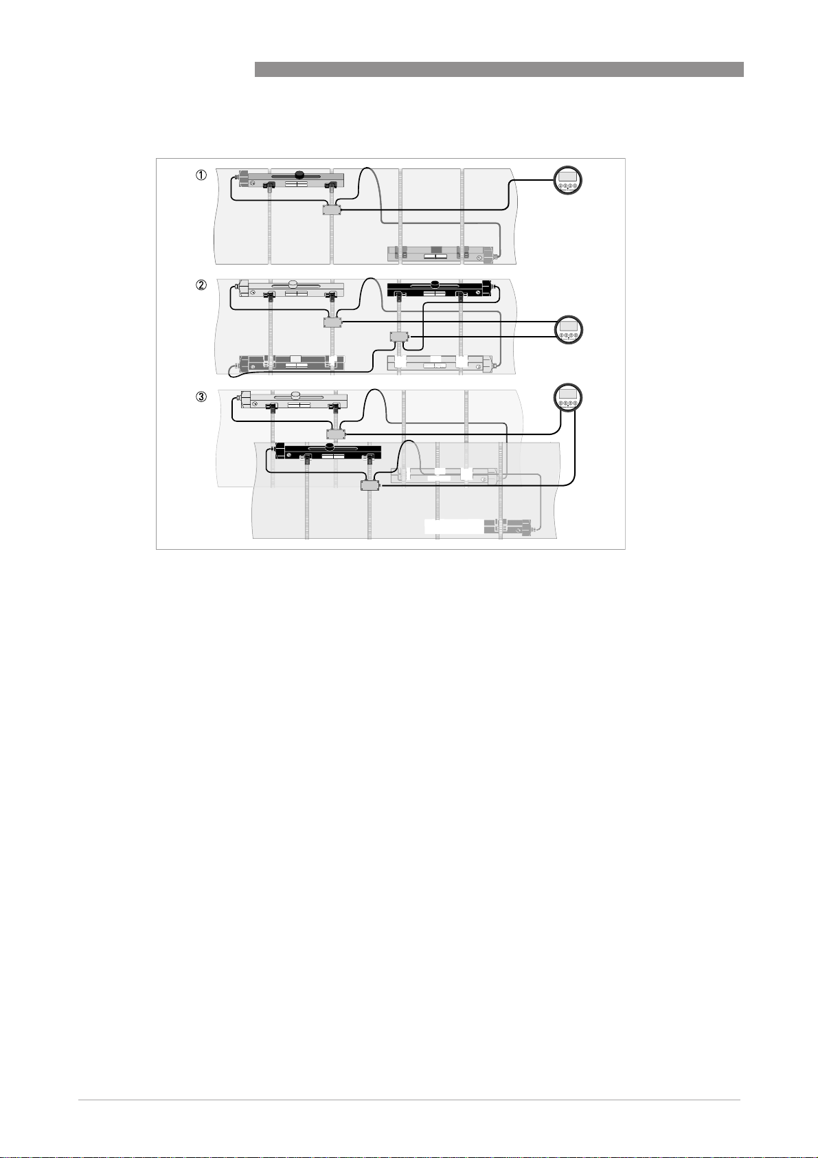
Figure 5-3: Device versions
1 Single pipe, single path
2 Single pipe, dual path
3 Dual pipe
www.krohne.com 07/2009 - 4000263902 - HB OPTISONIC 6300 R03 en
Page 63

OPTISONIC 6300
5.4 Mechanical installation for large version
INFORMATION!
You need a calculator, measuring band and pen & paper to install a large version.
Mounting the UP rail
Mounting the UP rail
Mounting the UP railMounting the UP rail
CAUTION!
Make sure that you mount the rail parallel to the pipe. Mount the fixing units and the cable box as
shown below.
START-UP 5
Figure 5-4: Mounting the large rail
1 Align the UP rail with the pipeline.
2 Fixing units
3 Turn screws clockwise to secure.
4 Mark the position.
5 Cable box
www.krohne.com07/2009 - 4000263902 - HB OPTISONIC 6300 R03 en
63
Page 64

5 START-UP
OPTISONIC 6300
64
Figure 5-5: Mounting large version rail
1 Pull the metal strap through the upper slit of the UP rail.
2 Take the metal strap around the pipe (45...60°).
3 Push the end of the metal strap in the lower slit of the fixing unit.
4 Take the other side of the metal strap around the pipe to the fixing unit.
5 Mount the cable box (only for downstream metal strap).
6 Push the metal strap through the upper slit of the fixing unit.
7 Pull the metal strap moderately tight by hand.
• Secure by turning screws clockwise.
www.krohne.com 07/2009 - 4000263902 - HB OPTISONIC 6300 R03 en
Page 65

OPTISONIC 6300
Mounting the DOWN rail in Z-mode
Mounting the DOWN rail in Z-mode
Mounting the DOWN rail in Z-modeMounting the DOWN rail in Z-mode
Set transducer positions for both rails according to the table below.
Advised distance [mm]
Advised distance [mm] Transducer position [mm]
Advised distance [mm]Advised distance [mm]
100...250 -65
>250 0
Measure the outer diameter of the pipe with a measuring band.
For Z-mode, you must install the DOWN rail at the opposite location at the pipe. There are two
possible ways to find the exact location:
1. FIND THE LOCATION WITH A FIXED REFERENCE POINT
Calculate the half of the outer diameter. Mark this 180° alignment line on the pipe.
Transducer position [mm]
Transducer position [mm]Transducer position [mm]
START-UP 5
Figure 5-6: Find the opposite location with a reference point
1 Measure the distance between the transducer of the UP rail and the reference point.
2 Add the Advised Distance and mark the location on the alignment line.
• Mount the DOWN rail in such a way that the transducer is at the marked location.
2. FIND THE LOCATION WITH THE SUPPLIED POSITIONING TOOL
www.krohne.com07/2009 - 4000263902 - HB OPTISONIC 6300 R03 en
65
Page 66

5 START-UP
Mount the positioning tool to the UP rail as shown.
OPTISONIC 6300
1 Mark the cables at a distance of 1.63 x outer diameter.
2 Outer diameter of pipeline
INFORMATION!
For large diameters you can use the weight of the metal plates to throw the cable around the
pipe. First release one of the cables in that case!
66
www.krohne.com 07/2009 - 4000263902 - HB OPTISONIC 6300 R03 en
Page 67

OPTISONIC 6300
Figure 5-7: Mark the pipelines with the V-mark
Pull the V-shaped plate in the downstream direction as much as possible. Pay attention that the cables are not obstructed.
Put the two V-marks on the pipeline.
Do the same in the upstream direction.
CAUTION!
Repeat above steps to check if you find the same points.
START-UP 5
Figure 5-8: Marking the opposite location
Calculate the middle of the alignment line between the 4 V-marks as shown.
www.krohne.com07/2009 - 4000263902 - HB OPTISONIC 6300 R03 en
67
Page 68

5 START-UP
Figure 5-9: Finding the location for the DOWN rail
1 Advised Distance as shown in menu X9.4
2 Measure the distance between the transducer and the end of the UP rail.
3 Determine and mark the location of the transducer of the DOWN rail: 3333 = 1111 - 2222
• Mount the DOWN rail in such a way that the transducer is at the marked location.
• Grease all transducers, see "General mechanical installation".
INFORMATION!
It can be necessary to install the DOWN rail as shown below.
OPTISONIC 6300
68
www.krohne.com 07/2009 - 4000263902 - HB OPTISONIC 6300 R03 en
Page 69

OPTISONIC 6300
Mounting the DOWN rail in V-mode
Mounting the DOWN rail in V-mode
Mounting the DOWN rail in V-modeMounting the DOWN rail in V-mode
For V-mode, you must install the DOWN rail in line with the UP rail. It is easier to install than the
Z-mode, but you need more free pipe length. V-mode is possible for DN450/600...2000 (minimum
depends on application).
START-UP 5
Figure 5-10: Mounting large version in V-mode
1 Fixing units
2 Reference marking
3 Cable box
4 Advised Distance, X9.4
5 Minimum distance between UP and DOWN rail: 110 mm / 4.3"
www.krohne.com07/2009 - 4000263902 - HB OPTISONIC 6300 R03 en
69
Page 70

5 START-UP
Electrical connections
Electrical connections
Electrical connectionsElectrical connections
Figure 5-11: Connections in cable box (large version)
1 Connect the blue cable to the UP rail.
2 Connect the green cable to the DOWN rail.
3 Make connections in cable box.
4 Cable to converter
5 Turn the screws clockwise to secure the caps.
OPTISONIC 6300
70
Figure 5-12: Construction of wall version
nd
1 Connect blue cable to 1U (to 2U for 2
2 Communication I/O
3 Power supply: 24 VAC/DC or 100...240 VAC
sensor) and the green cable to 1D (2D for 2nd sensor)
www.krohne.com 07/2009 - 4000263902 - HB OPTISONIC 6300 R03 en
Page 71

OPTISONIC 6300
Figure 5-13: Construction (field version)
1 Cover, electronics compartment
2 Cover, terminal compartment for power supply and inputs/outputs
3 Cable entry for power
4 Cable entry for inputs/outputs
5 Cable entry for sensor cable
6 Cover, sensor terminal compartment
START-UP 5
INFORMATION!
See also the section "Installation menu" in chapter "General instructions for programming".
• Go through menu X1...X7 as described in section "Installation menu" in chapter "General
instructions for programming". Correct X5 if needed.
• X9.1: Press enter
• X9.2: Press enter
• X9.3: Press enter
• X9.4: Press enter
• X9.5: Read the preliminary volume flow. Press enter
• X9.6: Check signal
CAUTION!
Advice on signal strength:
Advice on signal strength:
Advice on signal strength:Advice on signal strength:
Signal > 75%:
Signal > 75%: good signal, optimization loop not needed
Signal > 75%:Signal > 75%:
Signal 50...75%:
Signal 50...75%: fairly good signal, optimization loop can improve the signal
Signal 50...75%:Signal 50...75%:
Signal 10...50%:
Signal 10...50%: low signal, optimization loop needed
Signal 10...50%:Signal 10...50%:
Signal < 10%:
Signal < 10%: bad or no signal, check settings in menu X6, increase transducer distance and/or
Signal < 10%:Signal < 10%:
go into the optimization loop.
www.krohne.com07/2009 - 4000263902 - HB OPTISONIC 6300 R03 en
71
Page 72

5 START-UP
• X9.7: Confirm or adjust the reading with the actual distance on the rail.
• X9.8: Optimization loop. Repeat steps X9.8.1...X9.8.5 until the advised mounting distance does
not change more than 0.5%.
• X9.8.1: Optimise distance?
• X9.8.2: Read the velocity of sound of the fluid
• X9.8.3: Continue?
• X9.8.4: Confirm or adjust the velocity of sound
• X9.8.5: Read the advised mounting distance and reposition the transducer
• X9.9: Read the preliminary volume flow
• X9.10: Path ready? Enter "Yes". If you have:
1 path or pipe: you are finished, proceed with X9.12
2 paths: go to X9 for the 2
2 pipes: go to X10 for the 2
• X9.12: End Installation? If you enter "No" the installation is not saved, go to X9. If you enter
"Yes" the installation is saved and the measurement screen will appear.
• Mount the cover (see section "mounting the cover" in chapter "General mechanical
installation")
nd
nd
OPTISONIC 6300
path
pipe
72
www.krohne.com 07/2009 - 4000263902 - HB OPTISONIC 6300 R03 en
Page 73

OPTISONIC 6300
6.1 Menu overview
X installation
X1 language
X2 GDC IR interface
X3 units
X4 number of pipes
X5 number of paths
X6 pipe data
X7 pipe data 1
X8 pipe data 2
X9 install transd. 1
X10 install transd. 2
X12 transducer sets
A quick setup
A1 language
A2 Tag
A3 reset
A4 analog outputs
A5 digital outputs
A6 GDC IR interface
OPERATION 6
B test
B1 simulation
B2 actual values
B3 information
C setup
C1 process input 1
C2 process input 2
C3 process input
C4 transducer sets
C5 IO
C6 IO Counter
C7 IO HART
C8 device
INFORMATION!
You find the description of the X Installation
X Installation menu in Chapter 5 of this handbook
X InstallationX Installation
www.krohne.com07/2009 - 4000263902 - HB OPTISONIC 6300 R03 en
73
Page 74

6 OPERATION
6.2 Menu structure
6.2.1 Quick setup
OPTISONIC 6300
A1 language > english / german /
french
A2 Tag > fill in using ↑ ↓ > ^
A3 reset > A3.1, A3.2,… ↑ ↓
A3.1 reset errors yes/no ↑ ↓ ^
A3.2 counter 1 yes/no ↑ ↓ ^
A3.3 counter 2 yes/no ↑ ↓
(underneath counter becomes active if modular IO)
A3.4 counter 3 yes/no ↑ ↓ ^
(end)
A4 analog outputs > A4.1, A4.2,… ↑ ↓
A4.1 measurement > select from list
using ↑ ↓ >
use at all outputs ↑ ↓
yes/no ^
if no: only HART current
if yes: all analog outputs
A4.2 unit > select from list
using ↑ ↓ >
A4.3 range > fill in using ↑ ↓ > ^
use at all outputs ↑ ↓
yes/no ^
if no: only HART current
if yes: all analog outputs
A4.4 low flow cutoff > fill in using ↑ ↓ > ^
use at all outputs ↑ ↓
yes/no ^
if no: only HART current
if yes: all analog outputs
A4.5 time constant > fill in using ↑ ↓ > ^
use at all outputs ↑ ↓
yes/no ^
if no: only HART current
if yes: all analog outputs
A5 digital outputs > A5.1, A5.2,… ↑ ↓
A5.1 measurement > select from list
using ↑ ↓ >
↑ ↓ ^
output is selected
are selected
output is selected
are selected
output is selected
are selected
output is selected
are selected
^
^
^
74
www.krohne.com 07/2009 - 4000263902 - HB OPTISONIC 6300 R03 en
Page 75

OPTISONIC 6300
A6 GDC IR interface > activate/cancel ↑ ↓ ^
OPERATION 6
use at all outputs ↑ ↓
yes/no ^
if no: only pulse output
D is selected
if yes: all digital outputs
are selected
A5.2 pulse value unit > fill in using ↑ ↓ > ^
use at all outputs ↑ ↓
yes/no ^
if no: only pulse output
D is selected
if yes: all digital outputs
are selected
A5.3 value p. pulse > fill in using ↑ ↓ > ^
use at all outputs ↑ ↓
yes/no ^
if no: only pulse output
D is selected
if yes: all digital outputs
are selected
A5.4 low flow cutoff > fill in using ↑ ↓ > ^
use at all outputs ↑ ↓
yes/no ^
if no: only pulse output
D is selected
if yes: all digital outputs
are selected
www.krohne.com07/2009 - 4000263902 - HB OPTISONIC 6300 R03 en
75
Page 76

6 OPERATION
6.2.2 Test
B1 simulation > B1.1, B1.2,… ↑ ↓
B1.1 volume flow > set value/cancel ↑ ↓
(underneath B1.1 until B1.3 become active if two pipes or two paths
B1.1 volume flow 1 > set value/cancel ↑ ↓
B1.2 volume flow 2 > submenu
(end)
B1.4 vel. of sound > set value/cancel ↑ ↓
(underneath B1.4 until B1.5 become active if two pipes or two paths
B1.4 vel. of sound 1 > ↑ ↓
B1.5 vel. of sound 2 > submenu
(end)
B1.7 terminal A
B1.8 terminal B
B1.9 terminal C
B1.10 terminal D
B2 actual values > ↑ ↓
B.2.1 act. volume flow > ↑ ↓
(underneath B2.1.1 until B2.1.2 become active if two pipes
B2.1.1 pipe 1 read ^
B2.1.2 pipe 2 read ^
(end)
B.2.2 act. mass flow > ↑ ↓
(additional menus for two pipes)
B.2.3 act. Reynolds nr. > ↑ ↓
(additional menus for two pipes)
B.2.4 act. vel. of sound > ↑ ↓
(additional menus for two pipes)
(depends on IO
setting hardware)
(depends on IO
setting hardware)
(depends on IO
setting hardware)
(depends on IO
setting hardware)
start simulation ↑ ↓
yes/no ^
two pipes or two paths are selected in X4 and X5)
two pipes or two pathstwo pipes or two paths
start simulation ↑ ↓
yes/no ^
identical to B1.1
start simulation ↑ ↓
yes/no ^
two pipes or two paths are selected in X4 and X5)
two pipes or two pathstwo pipes or two paths
set value/cancel
start simulation ↑ ↓
yes/no ^
identical to B1.4
> select from list
> select from list
> select from list
> select from list
using ↑ ↓ >
using ↑ ↓ >
using ↑ ↓ >
using ↑ ↓ >
two pipes are selected in X4 and X5)
two pipestwo pipes
OPTISONIC 6300
↑ ↓
↑ ↓
^
^
^
^
76
www.krohne.com 07/2009 - 4000263902 - HB OPTISONIC 6300 R03 en
Page 77

OPTISONIC 6300
B3 information > B3.1, B3.2,… ↑ ↓
OPERATION 6
B.2.5 act. flow speed > ↑ ↓
(additional menus for two pipes)
B.2.6 act. gain > ↑ ↓
(additional menus for two pipes)
B.2.7 act. SNR > ↑ ↓
(additional menus for two pipes)
B.2.8 act. signal quality > ↑ ↓
(additional menus for two pipes)
B.2.9 operating hours > ↑ ↓
B3.1 C number read ^
B3.2 process input ↑ ↓
B3.2.1 sensor CPU read ^
B3.2.2 sensor DSP read ^
B3.2.3 sensor driver read ^
B3.3 device sernr/swnr/yymmdd↑ ↓ ^
B3.4 display sernr/swnr/yymmdd↑ ↓ ^
www.krohne.com07/2009 - 4000263902 - HB OPTISONIC 6300 R03 en
77
Page 78

6 OPERATION
6.2.3 Setup
C setup > ↑ ↓
(underneath C1 becomes active if two pipes
C1 process input 1 > C1.1, C1.3,… ↑ ↓ ^
C1.1 number of pipes > read ^
C1.3 pipe data > C1.3.1 ↑ ↓
C1.3.1 pipe tag
(further submenus C1.3.2 up to C1.3.12 are identical to X6.2 up to X6.13)
C1.4 transducer data > C1.4.1,... ↑ ↓ ^
C1.4.1 transducer set > Ta,Tb,Tc,none ↑ ↓ ^
C1.4.2 number of
C1.4.3 actual distance > fill in using ↑ ↓ > ^
C1.5 extra
C1.6 calibration > C1.6.1, C1.6.2,… ↑ ↓
C1.6.1 zero calibration > calibrate zero ? select cancel,
C1.6.2 meter factor > fill in using ↑ ↓ > ^
C1.6.3 Reynolds
C1.7 filter > C1.7.1, C1.7.2,… ↑ ↓ ^
C1.7.1 limitation > fill in using ↑ ↓ > ^
C1.7.2 flow direction > normal/reverse ↑ ↓ ^
C1.7.3 time constant > fill in using ↑ ↓ > ^
C1.7.4 low flow cutoff > fill in using ↑ ↓ > ^
C1.8 simulation > C1.8.1, C1.8.2,… ↑ ↓ ^
C1.8.1 volume flow > set value/cancel ↑ ↓
C1.8.2 vel. of sound > ↑ ↓
C1.9 plausibility > C1.9.1, C1.9.2,… ↑ ↓ ^
C1.9.1 error limit > fill in using ↑ ↓ > ^
C1.9.2 counter decrease > fill in using ↑ ↓ > ^
C1.9.3 counter limit > fill in using ↑ ↓ > ^
C1.10 information > C1.10.1,
C1.10.1 sensor CPU read
C1.10.2 sensor DSP read ^
C1.10.3 sensor driver read ^
C1.11 diagnosis value > fill in using ↑ ↓ > ^
C2 process input 2 > ↑ ↓
traverses
measurements
correction
OPTISONIC 6300
two pipes are selected in X4)
two pipestwo pipes
> 1,2,4 ↑ ↓ ^
> select on pipe 1,
> on,off ↑ ↓ ^
on pipe 2
automatic, default
start simulation ↑ ↓
yes/no ^
set value/cancel ↑ ↓
start simulation ↑ ↓
yes/no ^
↑ ↓ ^
C1.10.2,…
^
78
www.krohne.com 07/2009 - 4000263902 - HB OPTISONIC 6300 R03 en
Page 79

OPTISONIC 6300
(further submenus C2.1 up to C2.11 are identical to C1.1 up to C1.11)
(end)
(underneath C1 becomes active if two paths
C1 process input > C1.1, C1.2,… ↑ ↓
OPERATION 6
two paths are selected in X5)
two pathstwo paths
C1.1 number of pipes > read ^
C1.2 pipe 1: total paths > read ^
C1.3 pipe data > C1.3.1, C1.3.2,… ↑ ↓ ^
C1.3.1 pipe tag
(further submenus C1.3.2 up to C1.3.12 are identical to X6.2 up to X6.13)
C1.4 transducer data > C1.4.1, C1.4.2,… ↑ ↓
C1.4.1 transducer set 1 > Ta,Tb,Tc,none ↑ ↓ ^
C1.4.2 number of
traverses 1
C1.4.3 actual distance 1 > fill in using ↑ ↓ > ↑ ↓
C1.4.4 transducer set 2 > Ta,Tb,Tc,none ↑ ↓ ^
C1.4.5 number of
traverses 2
C1.4.6 actual distance 2 > fill in using ↑ ↓ > ↑ ↓
C1.6 calibration > C1.6.1, C1.6.2,… ↑ ↓ ^
C1.6.1 zero calibration > calibrate zero ? select cancel,
C1.6.2 meter factor > fill in using ↑ ↓ > ^
C1.6.3 Reynolds
correction
C1.7 filter > C1.7.1, C1.7.2,… ↑ ↓ ^
C1.7.1 limitation > fill in using ↑ ↓ > ^
C1.7.2 flow direction > normal/reverse ↑ ↓ ^
C1.7.3 time constant > fill in using ↑ ↓ > ^
C1.7.4 low flow cutoff > fill in using ↑ ↓ > ^
C1.8 simulation > C1.8.1, C1.8.2,… ↑ ↓ ^
C1.8.1 volume flow > set value/cancel ↑ ↓
C1.8.2 vel. of sound > set value/cancel ↑ ↓
C1.9 plausibility > C1.9.1, C1.9.2,… ↑ ↓ ^
C1.9.1 error limit > fill in using ↑ ↓ > ^
C1.9.2 counter decrease > fill in using ↑ ↓ > ^
C1.9.3 counter limit > fill in using ↑ ↓ > ^
C1.10 information > C1.10.1,
C1.10.1 sensor CPU read ^
C1.10.2 sensor DSP read ^
C1.10.3 sensor driver read ^
C1.11 diagnosis value > fill in using ↑ ↓ > ^
> 1,2,4 ↑ ↓ ^
> 1,2,4 ↑ ↓ ^
automatic, default
> on,off ↑ ↓ ^
start simulation ↑ ↓
yes/no
start simulation ↑ ↓
yes/no
↑ ↓ ^
C1.10.2,…
www.krohne.com07/2009 - 4000263902 - HB OPTISONIC 6300 R03 en
79
Page 80

6 OPERATION
C4 transducer sets > C4.1, C4.2,… ↑ ↓ ^
C4.1 Ta serial no. > fill in using ↑ ↓ > ^
C4.2 Ta calibration no. > fill in using ↑ ↓ > ^
C4.3 Tb serial no. > fill in using ↑ ↓ > ^
C4.4 Tb calibration no. > fill in using ↑ ↓ > ^
C4.5 Tc serial no. > fill in using ↑ ↓ > ^
C4.6 Tc calibration no. > fill in using ↑ ↓ > ^
C5 I/O > C5.1, C5.2,… ↑ ↓
C5.1 hardware > C5.1.1, C5.1.2,… ↑ ↓ ^
C5.1.1 terminals A > select current
C5.1.2 terminals B > select from list
C5.1.3 terminals C > select from list
C5.1.4 terminals D > select from list
C5.2 current out A > C5.2.1, C5.2.2,… ↑ ↓ ^
C5.2.1 range 0-100% > fill in using ↑ ↓ > ^
C5.2.2 extended range > fill in using ↑ ↓ > ^
C5.2.3 error current > fill in using ↑ ↓ > ^
C5.2.4 error condition > select from list
C5.2.5 measurement > select from list
C5.2.6 range > fill in using ↑ ↓ > ^
C5.2.7 polarity > select from list
C5.2.8 limitation > fill in using ↑ ↓ > ^
C5.2.9 low flow cutoff > fill in using ↑ ↓ > ^
C5.2.10 time constant > fill in using ↑ ↓ > ^
C5.2.11 special function > select from list
C5.2.12 threshold > fill in using ↑ ↓ > ^
C5.2.13 information > read ^
C5.2.14 simulation > select set
C5.2.15 4 mA trimming > fill in using ↑ ↓ > ^
C5.2.16 20 mA trimming > fill in using ↑ ↓ > ^
C5.3 frequency out X > C5.3.1, C5.3.2,… ↑ ↓ ^
C5.3.1 pulse shape > select from list
C5.3.2 pulse width > fill in using ↑ ↓ > ^
C5.3.3 100 % pulse rate > fill in using ↑ ↓ > ^
C5.3.4 measurement > select from list
C5.3.5 range > fill in using ↑ ↓ > ^
OPTISONIC 6300
^
output/off using ↑
↓
^
using ↑ ↓
^
using ↑ ↓
^
using ↑ ↓
^
using ↑ ↓
^
using ↑ ↓
^
using ↑ ↓
^
using ↑ ↓
^
on/off/cancel
^
using ↑ ↓
^
using ↑ ↓
80
www.krohne.com 07/2009 - 4000263902 - HB OPTISONIC 6300 R03 en
Page 81

OPTISONIC 6300
OPERATION 6
C5.3.6 polarity > select from list
using ↑ ↓
C5.3.7 limitation > fill in using ↑ ↓ > ^
C5.3.8 low flow cutoff > fill in using ↑ ↓ > ^
C5.3.9 time constant > fill in using ↑ ↓ > ^
C5.3.10 invert signal > fill in using ↑ ↓ > ^
C5.3.11 phase shift > select from list
using ↑ ↓
C5.3.12 special function > fill in using ↑ ↓ > ^
C5.3.13 information > read ^
C5.3.14 simulation > select set
on/off/cancel
C5.4 pulse output X > C5.4.1, C5.4.2,… ↑ ↓ ^
C5.4.1 pulse shape > select from list
using ↑ ↓
C5.4.2 pulse width fill in using ↑ ↓ > ^
C5.4.3 max. pulse rate > fill in using ↑ ↓ > ^
C5.4.4 measurement > select from list
using ↑ ↓
C5.4.5 pulse value unit > fill in using ↑ ↓ > ^
C5.4.6 value p. pulse > fill in using ↑ ↓ > ^
C5.4.7 polarity > select from list
using ↑ ↓
C5.4.8 low flow cutoff > fill in using ↑ ↓ > ^
C5.4.9 time constant > fill in using ↑ ↓ > ^
C5.4.10 invert signal > select on/off ^
C5.4.11 phase shift select from list
using ↑ ↓
C5.4.12 special function select from list
using ↑ ↓
C5.4.13 information > read ^
C5.4.14 simulation > select set
on/off/cancel
C5.5 status output X > C5.5.1, C5.5.2,… ↑ ↓ ^
C5.5.1 mode > select from list
using ↑ ↓
C5.5.2 current output Y > select from list
using ↑ ↓
C5.5.3 frequency output Y> select from list
using ↑ ↓
C5.5.4 pulse output Y > select from list
using ↑ ↓
C5.5.5 status output Y > select from list
using ↑ ↓
C5.5.6 limit switch Y > read: status off ^
C5.5.7 control input Y > read: status off ^
C5.5.8 off > read: status off ^
C5.5.9 invert signal > select on/off ^
C5.5.10 information > read ^
^
^
^
^
^
^
^
^
^
^
^
^
^
^
www.krohne.com07/2009 - 4000263902 - HB OPTISONIC 6300 R03 en
81
Page 82

6 OPERATION
OPTISONIC 6300
C5.5.11 simulation > select set
C5.6 limit switch X > C5.6.1, C5.6.2,… ↑ ↓ ^
C5.6.1 measurement > select from list
C5.6.2 threshold > fill in using ↑ ↓ > ^
C5.6.3 polarity > select from list
C5.6.4 time constant > fill in using ↑ ↓ > ^
C5.6.5 invert signal > select on/off ^
C5.6.6 information > read ^
C5.6.7 simulation > select set
C5.7 control input X > C5.7.1, C5.7.2,… ↑ ↓ ^
C5.7.1 mode > select from list
C5.7.2 invert signal > select on/off ^
C5.7.3 information > read ^
C5.7.4 simulation > select set
(active if HART device)
C6 I/O Counter > C6.1, C6.2 ↑ ↓
C6.1 counter 1 > C6.1.1, C6.1.2,… ↑ ↓ ^
C6.1.1 function of
counter
C6.1.2 measurement > select from list
C6.1.3 low flow cutoff > fill in using ↑ ↓ > ^
C6.1.4 time constant > fill in using ↑ ↓ > ^
C6.1.5 preset value > fill in using ↑ ↓ > ^
C6.1.6 reset counter > select yes/no ^
C6.1.7 set counter > select set
C6.1.8 stop counter > select yes/no ^
C6.1.9 start counter > select yes/no ^
C6.1.10 information > read ^
C6.2 counter 2 > C6.2.1, C6.2.2,… ↑ ↓
(underneath submenus identical to C6.1.1 to C6.1.10)
C7 I/O HART > C7.1, C7.2,… ↑ ↓
C7.1 PV is > C7.1.1, C7.1.2,… ↑ ↓ ^
C7.1.1 current output A > read ^
(depends on I/O configuration)
C7.1.2 frequency output X> read ^
> select from list
on/off/cancel
using ↑ ↓
using ↑ ↓
on/off/cancel
using ↑ ↓
on/off/cancel
using ↑ ↓
using ↑ ↓
on/off/cancel
^
^
^
^
^
^
^
^
^
82
C7.1.3 HART dynamic
variable
C7.2 SV is > C7.2.1
C7.2.1 HART dynamic
variable
> select from list
using ↑ ↓
> select from list
using ↑ ↓
www.krohne.com 07/2009 - 4000263902 - HB OPTISONIC 6300 R03 en
^
^
Page 83

OPTISONIC 6300
(end)
C8 device > C8.1, C8.2,… ↑ ↓
OPERATION 6
C7.3 TV is > C7.3.1
C7.3.1 HART dynamic
variable
C7.4 4V is > C7.4.1
C7.4.1 HART dynamic
variable
C8.1 device info > C8.1.1, C8.1.2,… ↑ ↓ ^
C8.1.1 Tag > fill in using ↑ ↓ > ^
C8.1.2 C number > read ^
C8.1.3 device serial no. > read ^
C8.1.4 electronic serial
no.
C8.1.5 information > read ^
C8.2 display > C8.2.1, C8.2.2,… ↑ ↓ ^
C8.2.1 language > select from list
C8.2.2 contrast > fill in using ↑ ↓ > ^
C8.2.3 default display > select from list
C8.2.5 information > read ^
C8.3 1. meas. page > C8.3.1, C8.3.2,… ↑ ↓
C8.3.1 function > select from list
(if two or three lines: C5.3.8 etc active)
C8.3.2 measurement
1.line
C8.3.3 range > fill in using ↑ ↓ > ^
C8.3.4 limitation > fill in using ↑ ↓ > ^
C8.3.5 low flow cutoff > fill in using ↑ ↓ > ^
C8.3.6 time constant > fill in using ↑ ↓ > ^
C8.3.7 format 1.line > select from list
C8.3.8 measurement
2.line
C8.3.9 format 2.line > select from list
C8.3.10 measurement
3.line
C8.3.11 format 3.line > select from list
C8.4 2. meas. page > C8.4.1, C8.4.2,… ↑ ↓
(underneath submenus identical to C8.3.1 to C8.3.11)
C8.5 graphic page > C8.5.1, C8.5.2,… ↑ ↓ ^
C8.5.1 select range > select
C8.5.2 range > fill in using ↑ ↓ > ^
C8.5.3 time scale > fill in using ↑ ↓ > ^
> select from list
using ↑ ↓
> select from list
using ↑ ↓
> read ^
using ↑ ↓
using ↑ ↓
using ↑ ↓
> select from list
using ↑ ↓
using ↑ ↓
> select from list
using ↑ ↓
using ↑ ↓
> select from list
using ↑ ↓
using ↑ ↓
manual/automatic
^
^
^
^
^
^
^
^
^
^
^
^
www.krohne.com07/2009 - 4000263902 - HB OPTISONIC 6300 R03 en
83
Page 84

6 OPERATION
C8.6 special functions > C8.6.1, C8.6.2,… ↑ ↓ ^
C8.6.1 reset errors > select yes/o ^
C8.6.2 save settings > select from list
C8.6.3 load settings > select from list
C8.6.4 password quick
C8.6.5 password setup > fill in 4 digits
C8.6.6 GDC IR interface > activate/cancel ^
C8.7 units > C8.7.1, C8.7.2,… ↑ ↓ ^
C8.7.1 size
C8.7.2 volume flow > select from list
C8.7.3 mass flow > select from list
C8.7.4 velocity > select from list
C8.7.5 volume > select from list
C8.7.6 mass > select from list
C8.7.7 density > select from list
C8.7.8 viscosity > select from list
C8.8 HART > C8.8.1, C8.8.2,… ↑ ↓ ^
C8.8.1 HART > select on/off ^
C8.8.2 address > fill in 2 digits
C8.8.3 message > fill in using ↑ ↓ > ^
C8.8.4 description > fill in using ↑ ↓ > ^
C8.9 quick setup > C8.9.1, C8.9.2,… ↑ ↓ ^
C8.9.1 reset counter 1 > select yes/no ^
C8.9.2 reset counter 2 > select yes/no ^
C8.9.3 reset counter 3 > select yes/no ^
setup
using ↑ ↓
using ↑ ↓
> fill in 4 digits
using ↑ ↓ >
using ↑ ↓ >
using ↑ ↓
using ↑ ↓
using ↑ ↓
using ↑ ↓
using ↑ ↓
using ↑ ↓
using ↑ ↓
using ↑ ↓ >
OPTISONIC 6300
^
^
^
^
^
^
^
^
^
^
^
^
84
www.krohne.com 07/2009 - 4000263902 - HB OPTISONIC 6300 R03 en
Page 85

OPTISONIC 6300
6.2.4 Customize settings
After installation the display switches to the first measurement screen.
The converter has 4 different display pages:
• 2 measurement pages
• 1 graphical page
• 1 status page
Using the ↓↑ buttons, you can switch between the displayed pages.
Customizing used transducers sets:
To alter settings in the menu, keep button > pressed until "Release key now" appears in the
display.
X12 transducer sets
X12 transducer sets > X12.1, X12.2,… ↑ ↓
X12.1 Ta serial no. > fill in using ↑ ↓ > ^
X12.2 Ta calibration no. > fill in using ↑ ↓ > ^
X12.3 Tb serial no. > fill in using ↑ ↓ > ^
X12.4 Tb calibration no. > fill in using ↑ ↓ > ^
X12.5 Tc serial no. > fill in using ↑ ↓ > ^
X12.6 Tc calibration no. > fill in using ↑ ↓ > ^
OPERATION 6
www.krohne.com07/2009 - 4000263902 - HB OPTISONIC 6300 R03 en
85
Page 86

6 OPERATION
OPTISONIC 6300
6.3 Function description
Menu No. Display Function description Selection list
XXXX Installation
X3
X3 units
X3X3
X3.1 size unit for dimension mm, inch
X3.2 volume flow unit for volume flow L/s, L/min,L/h, m3/s, m3/min, m3/h, m3/d,
X3.3 velocity unit for flow speed and velocity of
X3.4 density unit for density kg/L, kg/m3, lb/ft3, lb/gal, free unit
X3.5 viscosity unit for viscosity cSt, mm2/s
X5
X5 number of paths
X5X5
X6.3 diameter size for outer diameter of pipe min-max: 20 - 4300 mm / 0.787 - 169.3 inch
X6.4 pipe material carbon steel, stainless steel, cast iron,
X6.5 VoS pipe material min-max: 1000.0 - 4500.0 m/s / 3280.8 - 14764
X6.6 wall thickness min-max: 1.000 - 200.0 mm / 0.039 - 7.874 inch
X6.7 liner material cement, epoxy, PP, LDPE, HDPE, PTFE, rubber,
X6.8 VoS liner material min-max: 1000.0 - 4500.0 m/s / 3280.8 - 14764
X6.9 liner thickness min-max: 0.100 - 20.00 mm / 0.004 - 0.787 inch
X6.10 fluid water, alkanes, alcohols, oil, acids, CxHx
X6.11 VoS fluid min-max: 500 - 2500 m/s / 1640.4 - 8202.1 ft/s
X6.12 density min-max: 0.1000 - 5.0000 kg/l / 6.2428 lb/ft3 to
X6.13 viscosity min-max: 0.100 cSt to 9999 cSt (mm2/s)
X9.1 transducer set short code for transducer set,
X9.7 actual distance min-max: -10.00 - +9999 mm / -0.394 - +393.7
X12.1/3/5 Tx serial no. factory serial number of sensor Ayy, 5 free units
X12.2/4/6 Tx calibration no. set calibration number of sensor
Installation
InstallationInstallation
units
unitsunits
sound (VoS)
number of paths in case "2 paths" is selected, the
number of pathsnumber of paths
measurement results will be
averaged
mentioned on sensor
according to type sticker
ft3/s, ft3/min, ft3/h, gal/s, gal/min,gal/h, gal/d,
IG/s, IG/min, IG/h, IG/d, bbl/h, bbl/d, free unit
m/s, ft/s
1 path, 2 paths
aluminum, concrete, GRF/RFP, asbestos
cement, PP/PVC, acrylics, polyamide, other
ft/s
other, none
ft/s
refined, CxHx light, refrigerant, solvents,
caustic soda, other
312.14 lb/ft3
Ta, Tb, Tc, none
inch
9 free units
A Quick setup
AAAA quick setup
A1
A1 language
A1A1
A2
A2 Tag
A2A2
A4
A4 analog outputs
A4A4
A4.1 measurement value for HART current output (depends on pipe configuration: 1 or 2 pipes)
86
quick setup
quick setupquick setup
language english, german, french, dutch
languagelanguage
Tag unique location in plant 12 free selectable digits
TagTag
analog outputs only active if HART device current output A, B or C, pulse output A, B or D
analog outputsanalog outputs
volume flow, mass flow, VoS, flow speed, gain,
SNR, diagnosis value, volume flow 1 or 2, VoS 1
or 2
www.krohne.com 07/2009 - 4000263902 - HB OPTISONIC 6300 R03 en
Page 87

OPTISONIC 6300
OPERATION 6
A4.2 unit unit for HART current output L/s, L/min,L/h, m3/s, m3/min, m3/h, m3/d,
A4.3 range range for main HART current
A4.4 low flow cutoff low flow cutoff for main HART
A4.5 time constant time constant for main HART
A5
A5 digital outputs
A5A5
A5.1 measurement value for pulse output (depends on pipe configuration: 1 or 2 pipes)
A5.2 pulse value unit unit for main pulse output (unit class depends on selected measurement)
A5.3 value p. pulse value of pulse per volume or
A5.4 low flow cutoff low flow cutoff for pulse output (min-max depends on selected measurement)
digital outputs only active if HART device pulse output A, B or D, counter 1
digital outputsdigital outputs
output
current output
current output
mass for pulse output
ft3/s, ft3/min, ft3/h, gal/s, gal/min,gal/h, gal/d,
IG/s, IG/min, IG/h, IG/d, bbl/h, bbl/d, free unit
min-max: 0.00 - xxxx (depends on
configuration)
min-max: 00.0 - 20.0
min-max: 000.1 - 100.0
volume flow, mass flow, volume flow 1 or 2
(min-max depends on selected measurement)
B Test
BBBB test
B1.7 terminal A (depends on IO setting hardware) current output A, frequency output A, pulse
B1.8 terminal B (depends on IO setting hardware) current output B, frequency output B, pulse
B1.9 terminal C (depends on IO setting hardware) current output C, status output C, limit switch C
B1.10 terminal D (depends on IO setting hardware) frequency output D, pulse output D, status
B3.1 C number identification of electronics also see converter sticker;
B3.2.1 Sensor CPU identification of hardware and
B3.2.2 Sensor DSP identification of hardware and
B3.2.3 Sensor driver identification of hardware and
B3.3 Device identification of circuit board serial number of circuit board, main software
test
testtest
output A, status output A, limit switch A, control
input A
output B, status output B, limit switch B, control
input B
output D, limit switch D
first line: circuit board,
second line: software,
third line:calibration or production date
also see sensor board of electronics
software for flow processing
also see sensor board of electronics
software for signal processing
also see sensor board of electronics
software for driver part
version number, production date
C Setup
CCCC setup
C1.5 extra
C1.6.1 zero calibration transit time offset at zero flow cancel, default, automatic min-max: -10000 -
C1.6.2 meter factor set factor for correction of
C1.6.3 Reynolds
setup
setupsetup
measurements
correction
extra available parameters for
display or input/output
volume flow, mass flow, flow
speed and Reynolds number
set Reynolds correction for flow
profile disturbances, effective on
volume flow, mass flow
www.krohne.com07/2009 - 4000263902 - HB OPTISONIC 6300 R03 en
(only for dual pipe configuration: 1, 2 pipes)
on pipe 1: mass flow, flow speed, gain, SNR
on pipe 2: mass flow, flow speed, gain, SNR
+10000 ps
min-max: 0.500 - 2.000
on,off
87
Page 88

6 OPERATION
OPTISONIC 6300
C1.7.1 limitation set lower and upper limit for flow
C1.7.2 flow direction select flow direction normal, reverse
C1.7.3 time constant within set time, measurements
C1.7.4 low flow cutoff beneath set flow speed, zero
C1.8.2 vel. of sound simulation of the VoS min-max: 0.0000 - 2500.0 m/s / 0.0000 - 8202.1
C1.9.1 error limit with set limits, every erroneous
C1.9.2 counter decrease amount with which the counter
C1.9.3 counter limit totalized correct measurements
C1.11 diagnosis value diagnosis of the flow
C5.1
C5.1 I/O Hardware
C5.1C5.1
C5.1.1 terminals A assign terminal A for basic I/O: current output, off
C5.1.2 terminals B assign terminal B for basic I/O: status output, limit switch, control
C5.1.3 terminals C assign terminal C for basic I/O: status output, limit switch, off
C5.1.4 terminals D assign terminal D for basic I/O: status output, limit switch, pulse
C5.2
C5.2 current out A
C5.2C5.2
C5.2.1 range 0-100% set current range min-max: 04.0 - 20.0 mA
C5.2.2 extended range set upper current range to
C5.2.3 error current after error this selected current
C5.2.4 error condition error in device, out of specification, application
C5.2.5 measurement measurement value to current
C5.2.6 range set measurement range from 0
C5.2.7 polarity set polarity of current output positive -, negative -, both polarity(ies), absolute
C5.2.8 limitation set lower and upper limit for
C5.2.9 low flow cutoff beneath set value, current output
C5.2.10 time constant within set time, measurements
C5.2.11 special functions for ranging automatic range, external range, off
I/O Hardware
I/O HardwareI/O Hardware
current out A
current out Acurrent out A
speed on all outputs
are averaged, displayed and sent
to current output
appears in display
measurement is counted as
percentage of the measured
values
decreases
equal to set counter decrease,
decrease error limit by 1
measurement
extended value
is set
output
to 100 %
current output
is set to zero
are averaged, displayed and sent
to current output
min-max: -100 - +100 m/s
min-max: 000.0 - 100.0 s
min-max: 0.000 - 10.00 m/s / 0.000 - 32.81 ft/s
ft/s
min-max: 000 - 100 %
min-max: 00 - 99
min-max: 000 - 999
signal quality, Reynolds number
for Modular I/O: free selectable 1st IO Module
input
for Modular I/O: free selectable 2nd IO Module
for Modular I/O: fixed current out
output, frequency output, off
for Modular I/O: fixed current out
min-max: 03.5 - 21.5 mA
min-max: 03.0 - 22.0 mA
error
(depends on pipe configuration: 1 or 2)
volume flow, mass flow, VoS, flow speed, gain,
SNR, diagnosis value, volume flow 1 or 2, VoS 1
or 2
(min-max depends on parameter settings)
value
min-max: -150 - +150 %
min-max: 00.0 - 20.0
min-max: 000.1 - 100.0
88
www.krohne.com 07/2009 - 4000263902 - HB OPTISONIC 6300 R03 en
Page 89

OPTISONIC 6300
OPERATION 6
C5.2.12 threshold inactive if C5.2.11 is set to off: set
C5.2.13 information serial number of circuit board,
C5.2.14 simulation A simulation of current output A set value:on/off, cancel min-max: 00.0 - 22.0
C5.2.15 4 mA trimming restore factory setting for 4 mA min-max: 3.6000 - 5.5000 mA
C5.2.16 20 mA trimming restore factory setting for 20 mA min-max: 18.500 - 21.500 mA
C5.3
C5.3 frequency output
C5.3C5.3
C5.3.1 pulse shape set shape symmetric, automatic, fixed
C5.3.2 pulse width active if C2.3.1 is set to fixed: set
C5.3.3 100 % pulse rate min-max: 00000.0 - 10000.0
C5.3.4 measurement measurement value to frequency
C5.3.5 range set measurement range from 0
C5.3.6 polarity set polarity of frequency output both polarities
C5.3.7 limitation set lower and upper limit for
C5.3.8 low flow cutoff set low values to zero min-max: 00.0 - 20.0
C5.3.9 time constant within set time, measurements
C5.3.10 invert signal define frequency output
C5.3.11 phase shift phase shift between output B and D0, 90, 180 degrees
frequency output
frequency outputfrequency output
lag value between normal and
extended range
software version, calibration date
of circuit board
time for pulse activation
output
to 100 %
frequency output
are averaged, displayed and sent
to current output
activation
min-max: 05.0 - 80.0
mA
min-max: 0000.05 - 2000.00
(depends on pipe configuration: 1 or 2 pipes)
volume flow, mass flow, VoS, flow speed, gain,
SNR, diagnosis value, volume flow 1 or 2, VoS 1
or 2
(min-max depends on parameter settings)
min-max: -150 - +150 %
min-max: 000.1 - 100.0
off: activate high current/switch closed
on: low current/switch open
C5.3.12 special function for ranging off, phase shift
C5.3.13 information
C5.3.14 simulation simulation of frequency output on, off, cancel
C5.4
C5.4 pulse output
C5.4C5.4
C5.4.1 pulse shape set shape symmetric, automatic, fixed
C5.4.2 pulse width set time for pulse activation available if pulse shape is set: fixed min-max:
C5.4.3 max. pulse rate min-max: 00000.0 - 10000.0 Hz
C5.4.4 measurement measurement value to pulse
C5.4.5 pulse value unit unit for pulse output mL, L, free unit
C5.4.6 value p. pulse value of pulse per volume or
C5.4.7 polarity set polarity of pulse output positive -, negative -, both polarity(ies), absolute
C5.4.8 low flow cutoff set low values to zero min-max: 00.0 - 20.0
C5.4.9 time constant within set time, measurements
C5.4.10 invert signal activate switch closed, open off, on
pulse output
pulse outputpulse output
output
mass for pulse output
are averaged, displayed and sent
to current output
0000.05 - 2000.00
(depends on pipe configuration: 1 or 2 pipes)
volume flow, mass flow, volume flow 1 or 2
no min-max
value
min-max: 000.1 - 100.0
www.krohne.com07/2009 - 4000263902 - HB OPTISONIC 6300 R03 en
89
Page 90

6 OPERATION
C5.4.11 phase shift phase shift between output B and D0, 90, 180 degrees
C5.4.12 special function for ranging off, phase shift
C5.4.13 information serial number of circuit board,
C5.4.14 simulation simulation of pulse output on, off, cancel
C5.5
C5.5 status output
C5.5C5.5
C5.5.1 mode output is activated if an error
C5.5.2 current output Y active if selected under status
C5.5.3 frequency output Y active if selected under status
C5.5.4 pulse output D active if selected under status
C5.5.5 status output Y active if selected under status
C5.5.6 limit switch Y active if selected under status
C5.5.7 control input Y active if selected under status
C5.5.8 off active if selected under status
C5.5.9 invert signal define status output activation off: activate high current/switch closed
C5.5.10 information serial number of circuit board,
C5.5.11 simulation simulation of status output on, off, cancel
C5.6
C5.6 limit switch X
C5.6C5.6
C5.6.1 measurement measurement value to limit
C5.6.2 threshold 1e: switch level 2e:time lag min-max: 500.0 - 2500 m/s
C5.6.3 polarity set polarity of limit switch positive -, negative -, both polarity(ies), absolute
C5.6.4 time constant within set time, measurements
C5.6.5 invert signal define limit switch activation off: high current by exceeded limit
C5.6.6 information serial number of circuit board,
status output
status outputstatus output
limit switch X
limit switch Xlimit switch X
software version, calibration date
of circuit board
occurs
output mode (C2.5.1) output Y and
output is current output
output mode (C2.5.1) output Y and
output is frequency output
output mode (C2.5.1) output Y and
output is pulse output
output mode (C2.5.1) output Y and
output is status output
output mode (C2.5.1) output Y and
output is limit switch
output mode (C2.5.1) output Y and
output is control input
output mode (C2.5.1) output Y and
output is switched off
software version, calibration date
of circuit board
switch
are averaged, displayed and sent
to current output
software version, calibration date
of circuit board
(depends on pipe configuration: 1 or 2 pipes)
off, error in device, application error, out of
specification, empty pipe, polarity flow, over
range flow, application error 1 or 2, out of
specification 1 or 2, empty pipe 1 or 2, polarity
flow 1 or 2, over range flow 1 or 2, counter 1
preset, counter 2 preset, output A/B/C/D
polarity, over range, automatic range
polarity, over range
polarity, over range
same signal, inverted signal
off
off
off
on: low current/switch open
(depends on pipe configuration: 1 or 2 pipes)
volume flow, mass flow, VoS, flow speed, gain,
SNR, diagnosis value, volume flow 1 or 2, VoS 1
or 2
value
min-max: 000.1 - 100.0
on: low current by exceeded limit
OPTISONIC 6300
90
www.krohne.com 07/2009 - 4000263902 - HB OPTISONIC 6300 R03 en
Page 91

OPTISONIC 6300
C5.6.7 simulation simulation of limit switch on, off, cancel
C5.7
C5.7 control input X
C5.7C5.7
C5.7.1 mode define function of control input off, hold all outputs, hold output X, all outputs to
C5.7.2 invert signal off: activate a current
C5.7.3 information serial number of circuit board,
C5.7.4 simulation simulation of control input on, off, cancel
C6
C6 I/O Counter
C6C6
C6.1
C6.1…6.2
6.2 Counter 1 and 2
C6.1C6.1
6.26.2
C.x.1 function of counter define counter off, +counter, -counter, sum counters
C.x.2 measurement select the measurement for the
C.x.3 low flow cutoff set low values to zero (depends on parameter settings)
C.x.4 time constant within set time, measurements
C.x.5 preset value active when under status output
C.x.6 reset counter yes/no
C.x.7 set counter select set value on, off, cancel
C.x.8 stop counter stop counter and hold actual
C.x.9 start counter start after stop counter yes/no
C.x.10 information serial number of circuit board,
C7
C7 I/O HART
C7C7
C7.1 PV is Primary Variable; linked to HART
C7.1.1 current output A show selected value
C7.1.2 frequency output X show selected value
C7.1.3 HART dynamic
C7.2 SV is Secondary Variable; linked to
C7.3 TV is Third Variable
C7.4 4V is Fourth Variable
C8
C8 device
C8C8
C8.2.2 contrast min-max: -9 - +9
C8.2.3 default display 1.meas.page, 2.meas.page, graphic page,
control input X
control input Xcontrol input X
software version, calibration date
of circuit board
I/O Counter
I/O CounterI/O Counter
Counter 1 and 2 only if HART device
Counter 1 and 2Counter 1 and 2
counter
are averaged, displayed and sent
to current output
mode (C2.5.1) preset counter X is
selected
value
software version, calibration date
of circuit board
I/O HART only if HART device; HART
I/O HARTI/O HART
variable
device
devicedevice
dynamic values are linked to
analog outputs
current output
select the variable (depends on pipe configuration: 1 or 2 pipes)
frequency output D
zero, output X to zero, reset all counters, reset
counter X, stop all counters, stop counter X,
zero outp.+ stop cnt, range change X, error
reset
on: activate no current
(depends on pipe configuration: 1 or 2 pipes)
volume flow, mass flow, volume flow 1 or 2
min-max: 000.1 - 100.0
min-max: 0.00000 - 1.00 +15
yes/no
free selectable only if analog output is NOT
active
volume flow, mass flow, VoS, flow speed, gain,
SNR, diagnosis value, volume flow 1 or 2, VoS 1
or 2, counter 1 or 2, operating hours
status page, none
OPERATION 6
www.krohne.com07/2009 - 4000263902 - HB OPTISONIC 6300 R03 en
91
Page 92

6 OPERATION
OPTISONIC 6300
C8.3 settings for first and second
C8.3.1 function one, two, three line(s)
C8.3.2 measurement
1.line
C8.3.3 range set measurement range from 0
C8.3.4 limitation set lower and upper limit min-max: -150 - +150 %
C8.3.5 low flow cutoff set low values to zero min-max: 00.0 - 20.0
C8.3.6 time constant within set time, measurements
C8.3.7 format 1.line number of decimals automatic, No.x.xxxx (no - four decimals)
C8.3.8 measurement
2.line
C8.5.1 select range set Y-axis scaling manual, automatic
C8.5.2 range active if under select range
C8.5.3 time scale set X-axis scaling min-max: 001 - 100 min
C8.6.2 save settings factory settings, back up 1, back up 2, cancel
C8.6.3 load settings factory settings, back up 1, back up 2, cancel
C8.6.4 password quick
setup
C8.6.5 password setup 0000 - 9999
C8.7 units
C8.7.1 volume flow L/s, L/min,L/h, m3/s, m3/min, m3/h, m3/d,
C8.7.2 mass flow kg/s, kg/min, kg/h, t/min, t/h, t/d, lb/s, lb/min,
C8.7.3 flow speed m/s, ft/s
C8.7.4 velocity m/s, ft/s
C8.7.5 volume m3, in3, ft3, yd3, mL, L, hL, gal, IG, bbl, free unit
C8.7.6 mass mg, g, kg, t, oz, lb, ST, LT, free unit
C8.7.7 density kg/L, kg/m3, lb/ft3, lb/gal, free unit
C8.7.8 viscosity cSt, m2/s, mm2/s
C8.8.1 HART factory setting: HART
measurement display
(depends on pipe configuration: 1 or 2 pipes)
volume flow, mass flow, VoS, flow speed, gain,
SNR, diagnosis value, volume flow 1 or 2, VoS 1
or 2
(depends on parameter settings)
to 100 %
min-max: 000.1 - 100.0
are averaged, displayed and sent
to current output
bargraph, operating hours, counter 1, counter
2, diagnosis value, SNR, gain, flow speed, mass
flow, VoS, volume flow
min-max: -100 - +100%
(C5.5.1) manual is selected
0000 - 9999
ft3/s, ft3/min, ft3/h, gal/s, gal/min,gal/h, gal/d,
IG/s, IG/min, IG/h, IG/d, bbl/h, bbl/d, free unit
lb/h, ST/min, ST/h, ST/d, LT/h, LT/d, gs, g/min,
g/h, free unit
communication on; generates F:
application error open circuit A
92
www.krohne.com 07/2009 - 4000263902 - HB OPTISONIC 6300 R03 en
Page 93

OPTISONIC 6300
OPERATION 6
6.4 Error messages
Error
Error
Error Error
code
code
codecode
F (bold)
F (bold) error in device no measurement possible,
F (bold)F (bold)
F application
S out of
C check in
I information no direct impact on measurements no action needed
F (bold)
F (bold) IO 1 (or IO 2) error or failure of IO Module 1 (or 2)try to load settings (menu C8.6.3); if
F (bold)F (bold)
F (bold)
F (bold) parameter error or failure of data manager,
F (bold)F (bold)
F (bold)
F (bold) configuration incorrect configuration or no
F (bold)F (bold)
F (bold)
F (bold) display error of failure of display unit,
F (bold)F (bold)
F (bold)
F (bold) current output
F (bold)F (bold)
F (bold)
F (bold) software user
F (bold)F (bold)
F (bold)
F (bold) hardware
F (bold)F (bold)
F (bold)
F (bold) hardware
F (bold)F (bold)
F (bold)
F (bold) RAM/ROM
F (bold)F (bold)
F (bold)
F (bold) communication
F (bold)F (bold)
F (bold)
F (bold) front end malfunctioning of front end PCB contact manufacturer service
F (bold)F (bold)
F (bold)
F (bold) uproc malfunctioning of microcontroller
F (bold)F (bold)
F (bold)
F (bold) dsp malfunctioning of DSP contact manufacturer service
F (bold)F (bold)
F empty pipe signal lost at two paths check process conditions
F flow > max 1 max volume flow exceeded for pipe 1check parameter in menu C1.7.1
Group
Group
Group Group
message
message
messagemessage
error
specification
progress
Error
Error
Error Error
message
message
messagemessage
A (or B, C)
interface
settings
detection
error IO 1 (or IO
2)
dsp-up
Description
Description Error handling
DescriptionDescription
measured values are not valid
no measurement possible, but
device ok
unreliable measurement maintenance required, check
test function is active, device is
stand-by
parameter or hardware error
confirmation
parameter or hardware error
error or failure of the current
output A (or B, C), parameter or
hardware error
detected hardware and set
hardware settings do not match
hardware can not be detected defect; replace electronics units
no communication between DSP
and microprocessor PCB
PCB
Error handling
Error handlingError handling
repair or replace device and/or
CPU; contact manufacturer service
center
check parameter settings / power
off - wait 5 seconds - power on
device
flowprofile
wait until finished
error does not disappear, replace
electronics unit
try to load settings (menu C8.6.3); if
error does not disappear, replace
electronics unit
confirm change of module; if
configuration is unchanged,
replace electronics unit
defect; replace electronics units
defect; replace electronics units
defect; replace electronics units
follow display instructions
defect; replace electronics units
contact manufacturer service
center
center
contact manufacturer service
center
center
F flow > max 2 max volume flow exceeded for pipe 2check parameter in menu C1.7.1
F open circuit A
(or B, C)
F over range A
(or B, C)
current on current output A (or B,
C) too low
current on current output A (or B,
C) is limited by parameter setting
www.krohne.com07/2009 - 4000263902 - HB OPTISONIC 6300 R03 en
check cable or reduce resistance
(< 1000 Ohm)
extend upper or lower limit for
current output in menu C5.2.8
93
Page 94

6 OPERATION
Error
Error
Error Error
code
code
codecode
Group
Group
Group Group
message
message
messagemessage
Error
Error
Error Error
message
message
messagemessage
Description
Description Error handling
DescriptionDescription
Error handling
Error handlingError handling
OPTISONIC 6300
F over range A
(or B, D)
F active settings error during CRC check (Cyclic
F factory settings error during CRC check of factory
F back up 1 (or 2)
settings
F signal lost path 1signal lost at path 1 check signal cable / check for pipe
F signal lost path 2signal lost at path 2 check signal cable / check for pipe
F pipe/sens1
param.
F pipe/sens2
param.
S unreliable 1 unreliable measurement at pipe 1 check process conditions for gas
S unreliable 2 unreliable measurement at pipe 2 check process conditions for gas
S zero converter invalid value at power up power off - wait 5 seconds - power
S overflow
counter 1 (or 2,
3)
S backplane
invalid
I counter 1 (or 2,
3) stopped
I control input A
(or B) active
I over range
display 1 (or 2)
I backplane
sensor
I backplane
settings
I backplane
difference
I optical
interface
I softw sync
error
pulse on frequency output A (or B,
D) is limited by parameter setting
Redundancy Check) of the active
settings
settings
error during CRC check of back up
1 (or 2) settings
unrealistic parameter settings for
pipe in combination with path 1
unrealistic parameter settings for
pipe in combination with path 2
counter is overflowing and will
start again at zero
error during CRC check of
backplane
counter has stopped reset counter in menu C8.9.1 (or
information only no action needed
1st row on 1st (or 2nd)
measurement page is limited by
parameter setting
incompatible data sensor on
backplane
incompatible data on backplane
different data on backplane and
display
optical interface is operational,
local display can not be used
incompatible DSP and
microprocessor software
extend upper or lower limit for
frequency output in menu C5.3.7
load settings; factory setting, back
up 1 or back up 2
obstructions
obstructions
check parameters in menu X6
check parameters in menu X6
bubbles, solids
bubbles, solids
on device
no action needed
restore data records on backplane
C8.9.2, C8.9.3)
extend upper or lower limit for
limitation in menu C8.3.4
94
www.krohne.com 07/2009 - 4000263902 - HB OPTISONIC 6300 R03 en
Page 95

OPTISONIC 6300
7.1 Periodic maintenance
7.1.1 Regreasing of transducers
SERVICE 7
Figure 7-1: Greasing of transducers
• Loosen cover by unscrewing screw, slide cover away from connection cap, lift cover, place
cover in safe place to avoid damage.
• Push buttons to release the rail 1.
• Lift rail upward 2 and turn rail 90 degrees sideward 3.
Clean pipe and contact surfaces of transducers with a soft cloth.
• Regrease the contact surfaces of transducers 4.
• Turn rail 90 degrees back 5.
• Press rail at both ends to the pipe by clicking 6.
www.krohne.com07/2009 - 4000263902 - HB OPTISONIC 6300 R03 en
95
Page 96

7 SERVICE
7.2 Cleaning
Instructions for signal converter:
Instructions for signal converter:
Instructions for signal converter:Instructions for signal converter:
INFORMATION!
Each time a housing cover is opened, the thread should be cleaned and greased. Use only resinfree and acid-free grease.
Ensure that the housing gasket is properly fitted, clean and undamaged.
7.3 Exchange of electronics unit
Before opening the converter housing:
Before opening the converter housing:
Before opening the converter housing:Before opening the converter housing:
DANGER!
All work on the electrical connections may only be carried out with the power disconnected. Take
note of the voltage data on the nameplate!
WARNING!
Observe without fail the local occupational health and safety regulations. Any work done on the
electrical components of the measuring device may only be carried out by properly trained
specialists.
OPTISONIC 6300
INFORMATION!
Make notes of important specific data, before exchanging the electronics.
Menu settings are stored on the circuit board (or backplane), that is fixed to the housing. After
exchange of electronics unit and power-up, the following start up screen appears:
Load all data?
Load all data?
Load all data?Load all data?
• Select yes
i - if in the screen appears “load sensor data
compatible. You can proceed by selecting yes. Note that all settings need to be checked and
changed. Only the sensor calibration data are loaded.
- if in the screen appears “load no data
representative.
load sensor data”, the electronics units were not fully
load sensor dataload sensor data
load no data”, all data have been lost. Contact your local
load no dataload no data
96
www.krohne.com 07/2009 - 4000263902 - HB OPTISONIC 6300 R03 en
Page 97

OPTISONIC 6300
7.3.1 Field version
DANGER!
All work on the electrical connections may only be carried out with the power disconnected. Take
note of the voltage data on the nameplate!
SERVICE 7
Figure 7-2: Unscrew the cover and remove the display
Figure 7-3: Pull off printed circuit board
Perform the following procedures:
• Unscrew the display cover of the electronics compartment by hand, by turning it counter
clockwise 1.
• Remove the display by using two screwdrivers 2.
• Unscrew the two M4 screws 3 at the electronics unit 4.
• Pull the two metal pullers 5 at the left and right of the display, using a screwdriver or similar
tool and partially pull out the electronics unit.
CAUTION!
Please pay attention that the same amount of force is applied on both pullers, otherwise the
connector at the backside can be damaged.
www.krohne.com07/2009 - 4000263902 - HB OPTISONIC 6300 R03 en
97
Page 98

7 SERVICE
Figure 7-4: Small printed circuit board and electronics unit
OPTISONIC 6300
DANGER!
Electrostatic discharge (ESD) can damage electronic parts. Make sure to discharge yourself by
wearing a wrist strap. If no wrist strap is available, ground yourself by touching a metal surface
that is grounded.
• Remove the printed circuit board 6 from the electronics unit 4.
• Check compatibility between the removed and new electronics unit 4, by checking the power
voltage.
• Slide the new electronics unit 4 partially back into the housing.
• Mount the small printed circuit board back onto the electronics unit 4.
• Push the metal pullers 5 back to their original position.
Don't use excessive force, otherwise the connector at the backside can be damaged!
• Screw the electronics unit back to the housing.
• Re-install the display and make sure not to kink the display's flat ribbon cable.
• Replace cover and tighten by hand.
• Connect power.
98
www.krohne.com 07/2009 - 4000263902 - HB OPTISONIC 6300 R03 en
Page 99

OPTISONIC 6300
7.3.2 Wall version
DANGER!
All work on the electrical connections may only be carried out with the power disconnected. Take
note of the voltage data on the nameplate!
Figure 7-5: Unlock and open door
SERVICE 7
Perform the following procedures:
• Turn locking screw to the left 1 to unlock the lower door.
• Open lower door.
• Slide metal slider, positioned at the left upper angle, downwards.
• Open upper door 2.
www.krohne.com07/2009 - 4000263902 - HB OPTISONIC 6300 R03 en
99
Page 100

7 SERVICE
Figure 7-6: Remove the display
• Remove the display 3 by pressing the plastic holders on both sides 4 and carefully lay the
display aside.
• Unscrew the two M4 screws 7 at the electronics unit 5.
OPTISONIC 6300
100
Figure 7-7: Release printed circuit board
• Remove the small printed circuit board 6with care.
• Carefully slide the electronics unit 5, then lift it out of the housing.
www.krohne.com 07/2009 - 4000263902 - HB OPTISONIC 6300 R03 en
 Loading...