

Page 1

Quick Start
Quick Start
OPTISONIC 6300
OPTISONIC 6300
OPTISONIC 6300OPTISONIC 6300
Quick Start Quick Start
Ultrasonic clamp-on flowmeter
ER 3.4.0_
© KROHNE 07/2009 - 7.30959.24.00 - QS OPTISONIC 6300 R04 en
Page 2

CONTENTS
OPTISONIC 6300
1 Installation 4
1.1 Intended use ..................................................................................................................... 4
1.2 Scope of delivery............................................................................................................... 4
1.3 Overview............................................................................................................................ 5
1.4 Storage ............................................................................................................................. 5
1.5 Transport .......................................................................................................................... 5
1.6 Pre-installation requirements ......................................................................................... 6
1.6.1 Environmental requirements ................................................................................................. 6
1.6.2 Installation requirements signal converter ........................................................................... 6
1.7 Installation requirements sensor .................................................................................... 6
1.7.1 Inlet, outlet and recommended mounting area ..................................................................... 7
1.7.2 Long horizontal pipes ............................................................................................................. 7
1.7.3 Open feed or discharge........................................................................................................... 8
1.7.4 Down going pipeline over 5 m /16 ft length............................................................................ 8
1.7.5 Position of control valve.......................................................................................................... 8
1.7.6 Position of pump .....................................................................................................................9
1.7.7 Pipe diameters and sensor construction ............................................................................... 9
1.7.8 Pipe and media parameters ................................................................................................... 9
1.8 Installation of the flowmeter.......................................................................................... 10
1.8.1 General mechanical installation........................................................................................... 10
1.8.2 Installation instructions for small and medium version...................................................... 12
1.8.3 Installation instructions for large version............................................................................ 14
1.9 Mounting of converter .................................................................................................... 16
1.9.1 Mounting of UFC 300 F.......................................................................................................... 16
1.9.2 Turning the display of the field housing version .................................................................. 16
1.9.3 Mounting of UFC 300 W......................................................................................................... 17
2 Electrical connections 18
2.1 Safety instructions.......................................................................................................... 18
2.2 Construction of the various housing versions ............................................................... 18
2.2.1 UFC 300 F .............................................................................................................................. 18
2.2.2 UFC 300 W ............................................................................................................................. 19
2.3 Electrical connection......................................................................................................20
2.3.1 Signal cable to flow sensor................................................................................................... 20
2.3.2 Signal cable and power supply signal converter.................................................................. 22
2.3.3 Signal cable to converter ...................................................................................................... 24
2.3.4 Laying electrical cables correctly......................................................................................... 24
2.4 Inputs and outputs, overview ......................................................................................... 25
2.4.1 Fixed, non-alterable input/output versions.......................................................................... 25
2.4.2 Alterable input/output versions............................................................................................ 27
3 Start-up 28
3.1 General instructions for programming.......................................................................... 28
3.2 Start measurement of small / medium version ............................................................ 32
3.3 Start measurement of large version.............................................................................. 33
3.4 Mechanical installation for large version ...................................................................... 35
2
www.krohne.com 07/2009 - 7.30959.24.00 - QS OPTISONIC 6300 R04 en
Page 3

OPTISONIC 6300
CONTENTS
4 Technical data 45
4.1 Technical data................................................................................................................. 45
5 Notes 53
www.krohne.com07/2009 - 7.30959.24.00 - QS OPTISONIC 6300 R04 en
3
Page 4
1 INSTALLATION
1.1 Intended use
The overall functionality of the clamp-on flowmeter is the continuous measurement of actual
volume flow, mass flow, flow speed, velocity of sound, gain, SNR and diagnosis value.
1.2 Scope of delivery
INFORMATION!
Check the packing list to check if you received completely all that you ordered.
INFORMATION!
Inspect the cartons carefully for damage or signs of rough handling. Report damage to the
carrier and to the local office of the manufacturer.
INFORMATION!
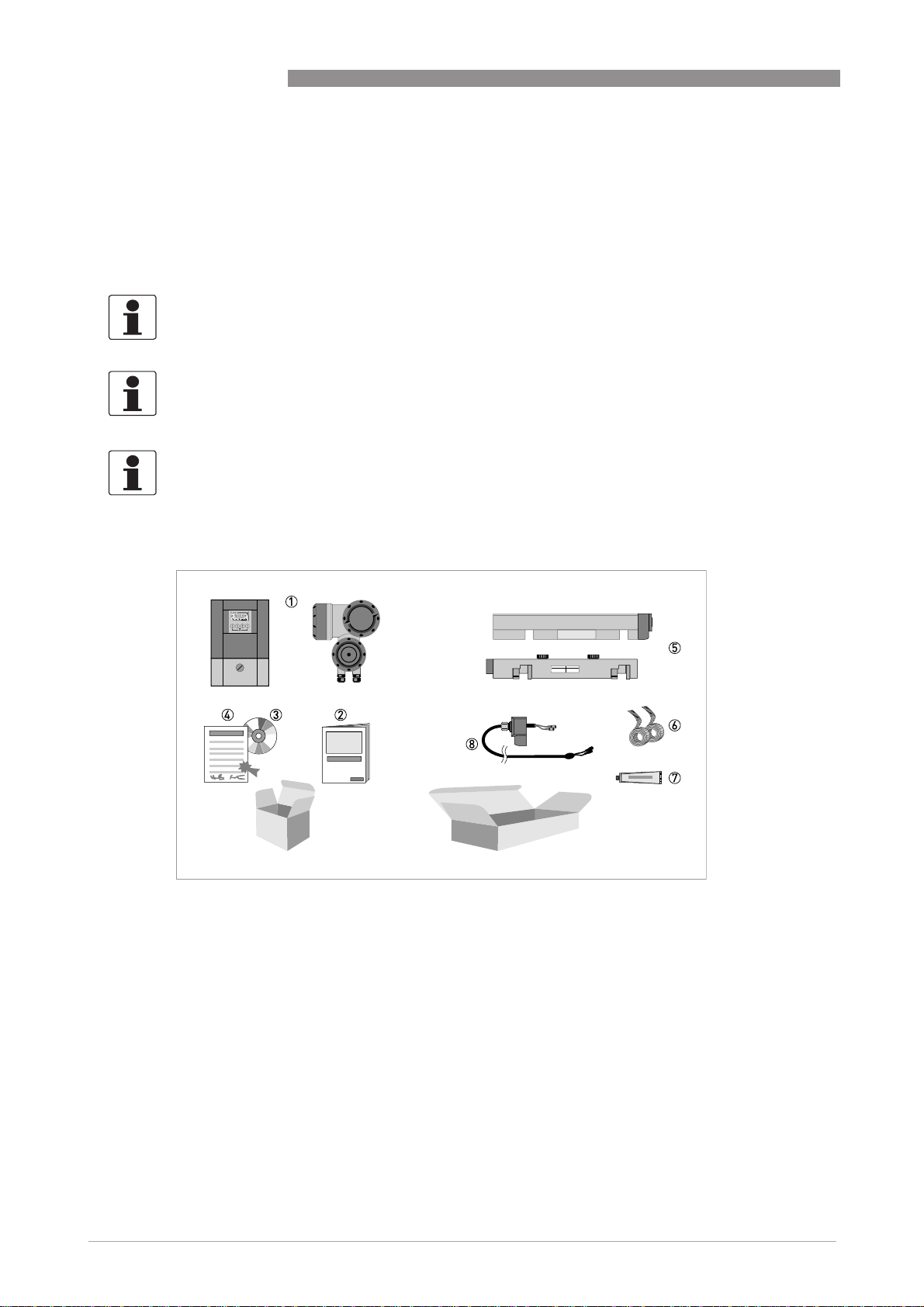
The device will arrive in two cartons. The square carton contains the converter. The rectangular
carton contains the transducer set.
OPTISONIC 6300
Figure 1-1: Scope of delivery
1 Signal converter, wall version or field version
2 Quick Start
3 CD-ROM (including Handbook, Quick Start, Technical Datasheet, Support database, movie)
4 Factory calibration report
5 Sensor plus cover (stainless steel / XT version without cover)
6 Metal strap
7 Mineral coupling grease (standard versions) or high temperature contactgel Pyrogel
8 Signal cable plus connector cap (XT versions have a protection sleeve around the signal cable).
4
www.krohne.com 07/2009 - 7.30959.24.00 - QS OPTISONIC 6300 R04 en
®
(XT versions)
Page 5
OPTISONIC 6300
Additionally for large version:
1 2nd sensor plus cover
2 90 degree screw driver
3 4 fixing units
4 Positioning tool
5 2 metal straps
6 Signal cable plus connector cap
7 Cable box plus signal cable
INFORMATION!
No special tools, no training required!
INSTALLATION 1
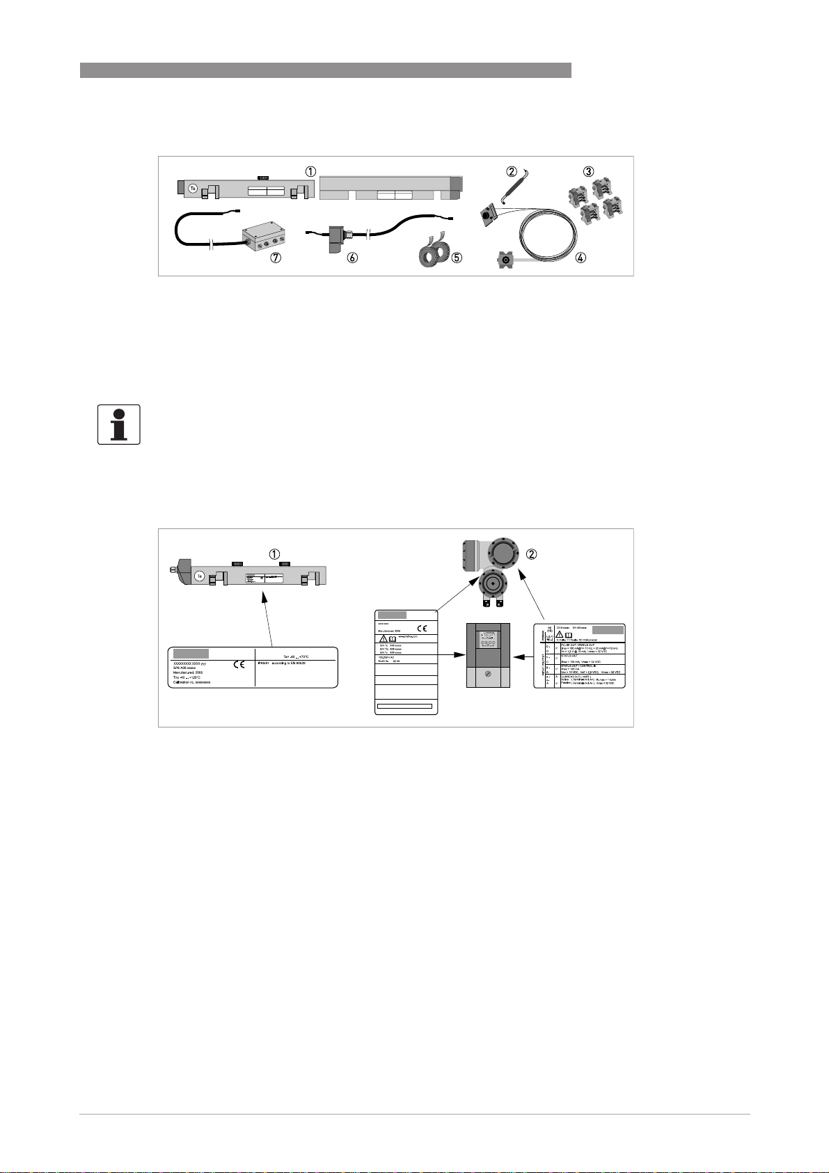
1.3 Overview
Figure 1-2: Visual check
1 Flow sensor
2 Signal converter
1.4 Storage
• Store the flowmeter in a dry and dust-free location.
• Avoid lasting direct exposure to the sun.
• Store the flowmeter in its original packing.
1.5 Transport
No special requirements.
www.krohne.com07/2009 - 7.30959.24.00 - QS OPTISONIC 6300 R04 en
5
Page 6

1 INSTALLATION
1.6 Pre-installation requirements
INFORMATION!
To assure a quick, safe and uncomplicated installation, we kindly request you to make provisions
as stated below.
1.6.1 Environmental requirements
• Pollution degree 2
• Protection class I
• Humidity: 5...80 % RH
• Temperature: –40…+60°C / -40…+140°F operating and –50…+70°C / -58…+158°F storage
• Suitable for indoor and outdoor use and certified for operating up to an altitude of
2000 m / 6562 ft
• IP class 66/67
CAUTION!
The device should be protected from corrosive chemicals or gases and dust / particles
accumulation.
OPTISONIC 6300
1.6.2 Installation requirements signal converter
• Allow 10…20 cm / 3.9…7.9" of space at the sides and rear of the signal converter to permit
free air circulation.
• Protect signal converter against direct solar radiation, install a sunshield if necessary.
• Signal converters installed in switchgear cabinets require adequate cooling, e.g. by fan or
heat exchanger.
• Do not expose the signal converter to intense vibration.
1.7 Installation requirements sensor
INFORMATION!
To avoid measuring errors and malfunctioning of the flowmeter due to gas or air inclusions or an
empty pipe, please observe the following precautions.
CAUTION!
Since gas will collect at the highest point of a pipe, installation of the flowmeter at that location
should be avoided at all times. Also installation in a down going pipe should be avoided since a
completely filled pipe may not be guaranteed due to cascading effects. Additionally flow profile
distortion is possible.
CAUTION!
If you program the diameter, please note that you use the outer diameter of the pipe.
6
www.krohne.com 07/2009 - 7.30959.24.00 - QS OPTISONIC 6300 R04 en
Page 7
OPTISONIC 6300
1.7.1 Inlet, outlet and recommended mounting area
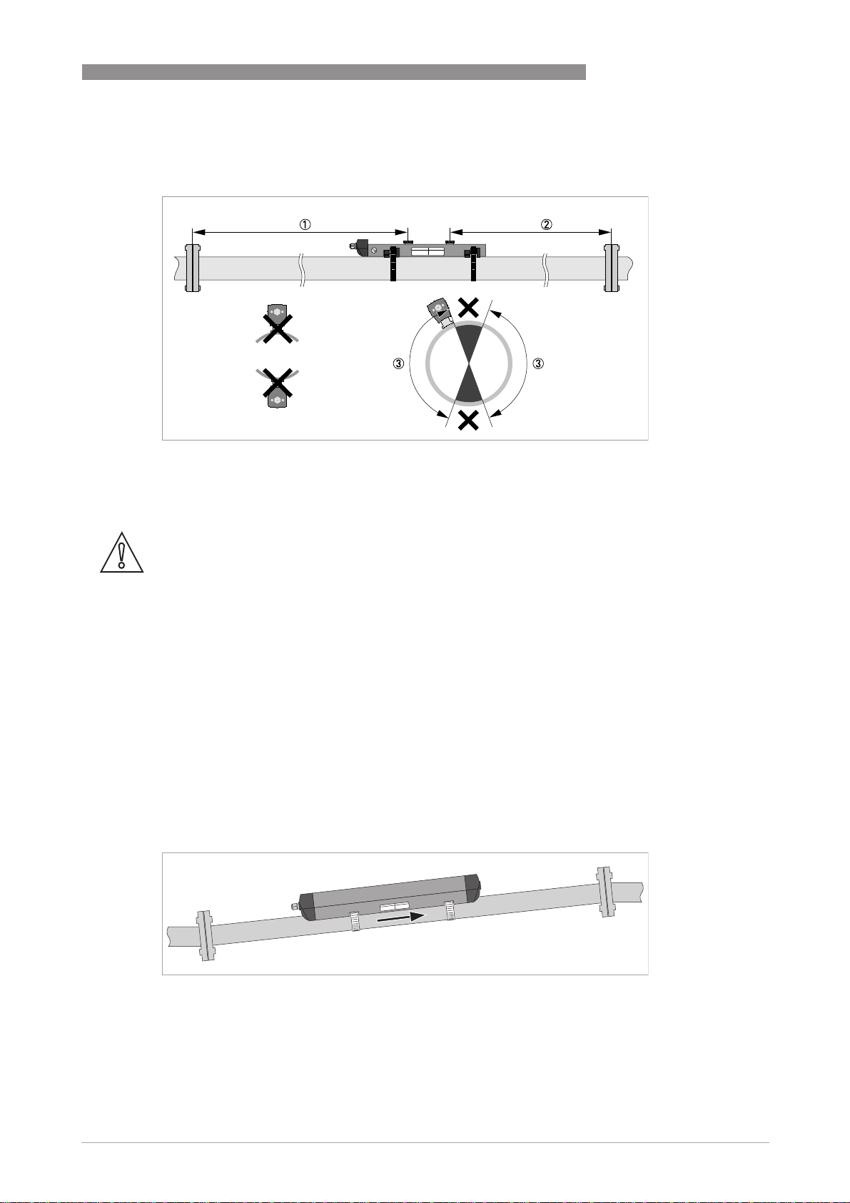
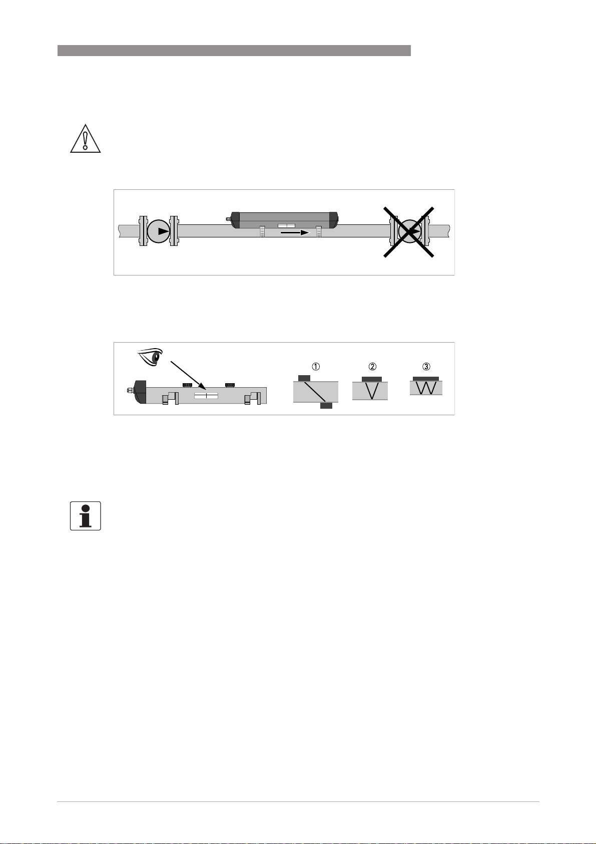
Figure 1-3: Inlet, outlet and recommended mounting area
1 Min. 10 DN
2 Min. 5 DN
3 OK, 120°
INSTALLATION 1
CAUTION!
Especially for XT (eXtended Temperature) versions:
•
Always install the sensor at a non-insulated part of the pipe. Remove any insulation if
necessary!
•
Bend radius of cable plus connection box needs 10 cm / 4" additional non insulated pipe
section.
•
Always wear protections gloves.
1.7.2 Long horizontal pipes
• Install on slightly ascending pipe section.
• If not possible, ensure adequate velocity to prevent air, gas or vapor from collecting in upper
part.
• In partially filled pipes, the clamp-on flowmeter will report incorrect flow rates, or not
measure.
Figure 1-4: Long horizontal pipes
www.krohne.com07/2009 - 7.30959.24.00 - QS OPTISONIC 6300 R04 en
7
Page 8
1 INSTALLATION
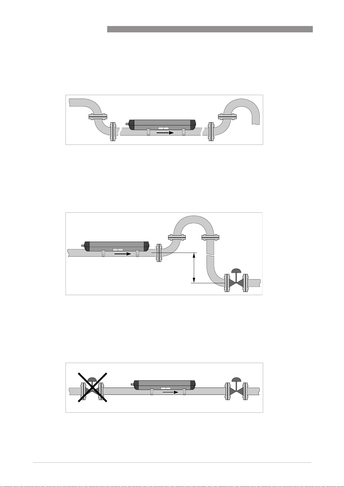
1.7.3 Open feed or discharge
Install meter on a lowered section of the pipe to ensure a full pipe condition through the meter.
Figure 1-5: Open feed or discharge
1.7.4 Down going pipeline over 5 m /16 ft length
Install air vent downstream of the flow meter to prevent vacuum. Although this will not harm the
meter, it may cause gases to come out of solution (cavitate) and interfere with proper
measurements.
OPTISONIC 6300
Figure 1-6: Down going pipeline over 5 m /16 ft length
1.7.5 Position of control valve
Always install control valves downstream of flowmeter in order to avoid cavitation or distortion
of flow profile.
Figure 1-7: Position of control valve
8
www.krohne.com 07/2009 - 7.30959.24.00 - QS OPTISONIC 6300 R04 en
Page 9
OPTISONIC 6300
1.7.6 Position of pump
CAUTION!
Never install flowmeter at a pump suction side in order to avoid cavitation or flashing in the
flowmeter.
Figure 1-8: Position of pump
1.7.7 Pipe diameters and sensor construction
INSTALLATION 1
Figure 1-9: Measuring modes
1 Z-mode
2 V-mode
3 W-mode
1.7.8 Pipe and media parameters
INFORMATION!
Detailed databases of most pipe and media parameters are on the supplied CD.
www.krohne.com07/2009 - 7.30959.24.00 - QS OPTISONIC 6300 R04 en
9
Page 10
1 INSTALLATION
1.8 Installation of the flowmeter
1.8.1 General mechanical installation
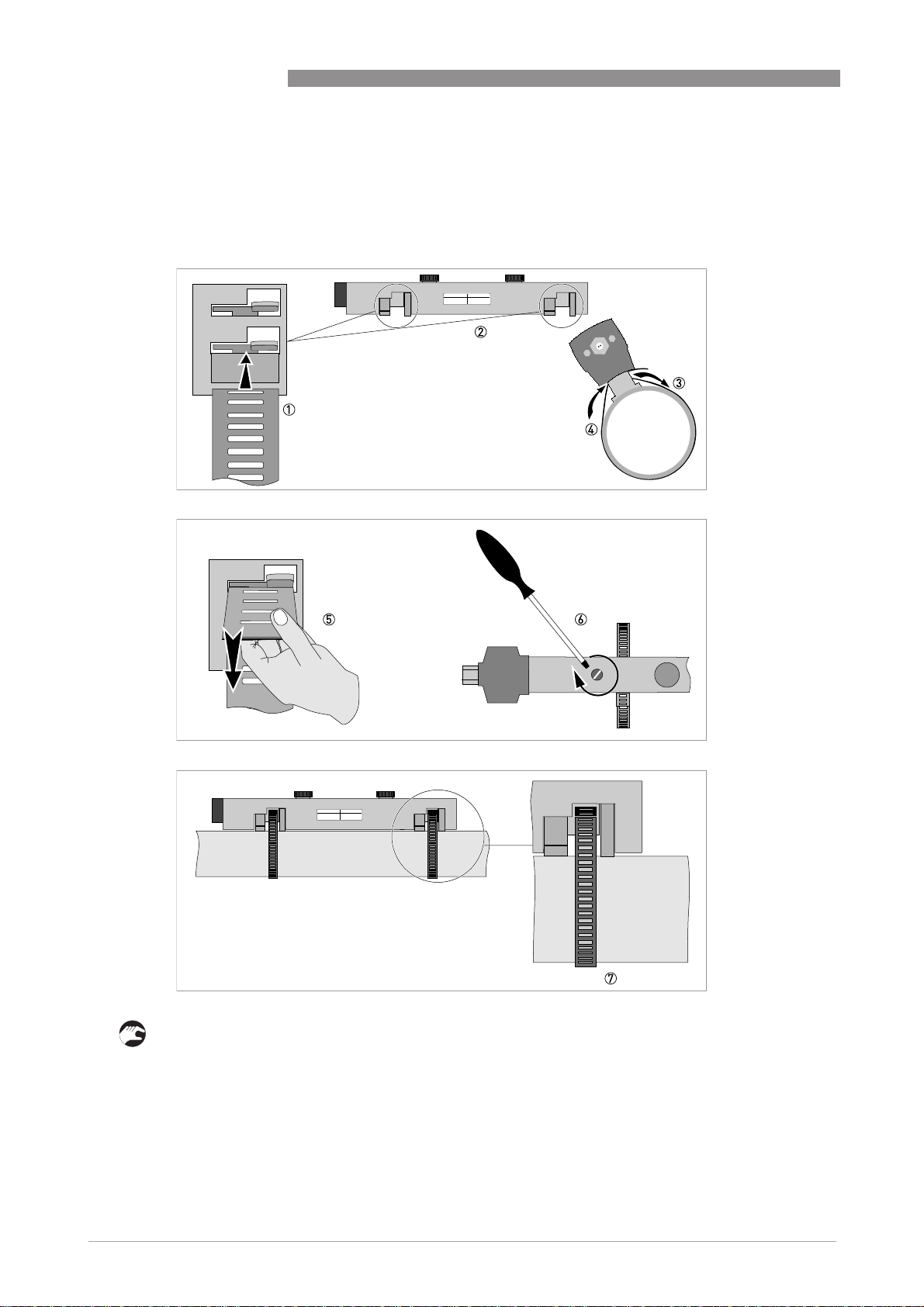
Installation of the rails with the metal straps
Installation of the rails with the metal straps
Installation of the rails with the metal strapsInstallation of the rails with the metal straps
OPTISONIC 6300
10
• 8: Repeat steps 1...7 at the other side of the rail.
www.krohne.com 07/2009 - 7.30959.24.00 - QS OPTISONIC 6300 R04 en
Page 11
OPTISONIC 6300
Change the position of the transducer
Change the position of the transducer
Change the position of the transducerChange the position of the transducer
• Unlock the floating transducer 2 by turning the locking knob 1 counter clockwise.
• Slide the transducer 2 to the advised mounting distance 3 (menu X9.4).
• Lock the transducer by turning the locking knob 1 clockwise.
Greasing the transducer surfaces
Greasing the transducer surfaces
Greasing the transducer surfacesGreasing the transducer surfaces
INSTALLATION 1
www.krohne.com07/2009 - 7.30959.24.00 - QS OPTISONIC 6300 R04 en
11
Page 12
1 INSTALLATION
INFORMATION!
Not applicable for stainless steel / XT versions. These are delivered without cover.
Mounting the cover
Mounting the cover
Mounting the coverMounting the cover
OPTISONIC 6300
1.8.2 Installation instructions for small and medium version
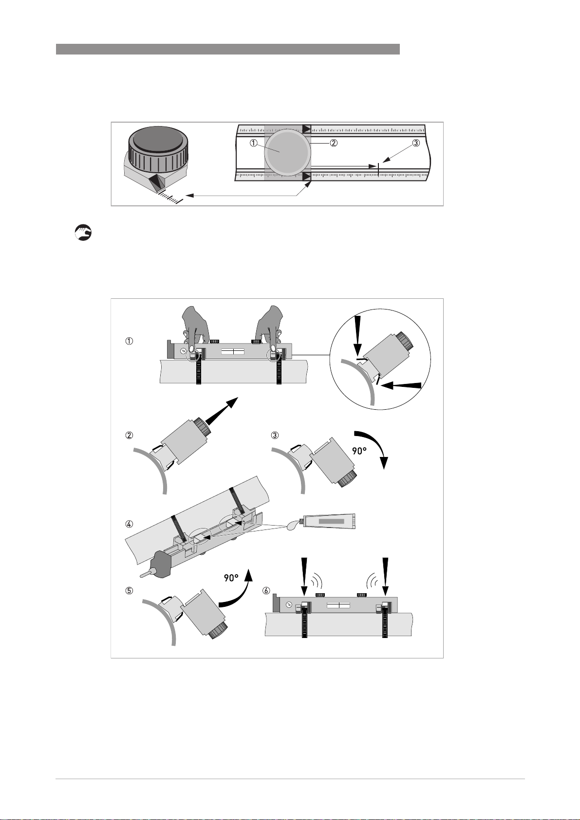
Figure 1-10: Procedure for installation of small or medium version
1 Rail, small version
2 Rail, medium version
3 Choose for V-mode or ...
4 Choose for W-mode
5 Make settings in converter
12
www.krohne.com 07/2009 - 7.30959.24.00 - QS OPTISONIC 6300 R04 en
Page 13

OPTISONIC 6300
INSTALLATION 1
Figure 1-11: Device versions
1 Small version: single pipe / single path
2 Medium version: single pipe / single path
3 Small version: single pipe / dual path
4 Medium version: single pipe / dual path
5 Small version: dual pipe / single path
6 Medium version: dual pipe / single path
www.krohne.com07/2009 - 7.30959.24.00 - QS OPTISONIC 6300 R04 en
13
Page 14
1 INSTALLATION
1.8.3 Installation instructions for large version
OPTISONIC 6300
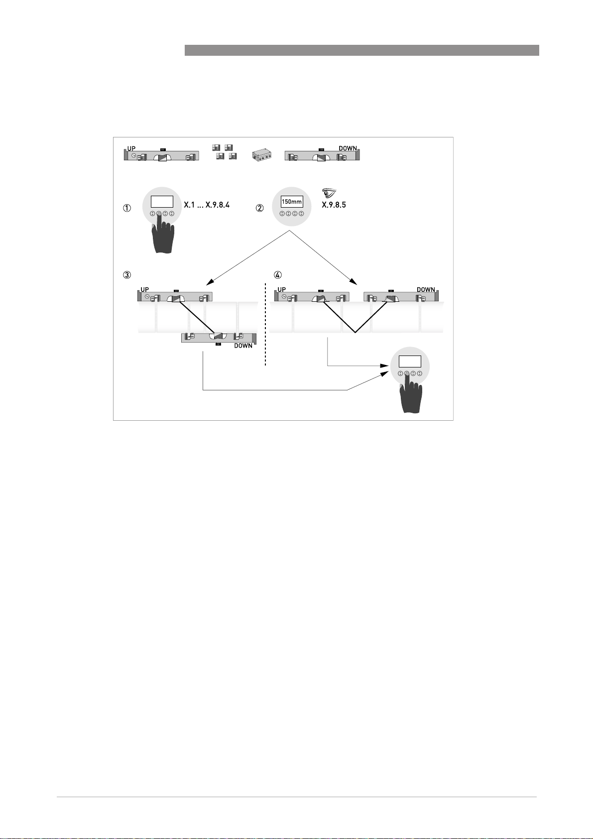
Figure 1-12: Procedure for installation of large version
1 Enter the values for the installation menu, X1...X9.8.4
2 Read the advised mounting distance in menu X9.8.5
3 Choose for Z-mode (default) or ...
4 Choose for V-mode
5 Finish the installation menu
14
www.krohne.com 07/2009 - 7.30959.24.00 - QS OPTISONIC 6300 R04 en
Page 15
OPTISONIC 6300
INSTALLATION 1
Figure 1-13: Device versions
1 Single pipe, single path
2 Single pipe, dual path
3 Dual pipe
www.krohne.com07/2009 - 7.30959.24.00 - QS OPTISONIC 6300 R04 en
15
Page 16
1 INSTALLATION
1.9 Mounting of converter
CAUTION!
Always use the supplied signal cable. Keep the distance between the sensor and the signal
converter as short as possible.
1.9.1 Mounting of UFC 300 F
Perform the following procedures:
• Mount converter with mounting plate on wall or standpipe.
• Observe maximum allowed length of 30 m / 98.4 ft for the signal cable
1.9.2 Turning the display of the field housing version
OPTISONIC 6300
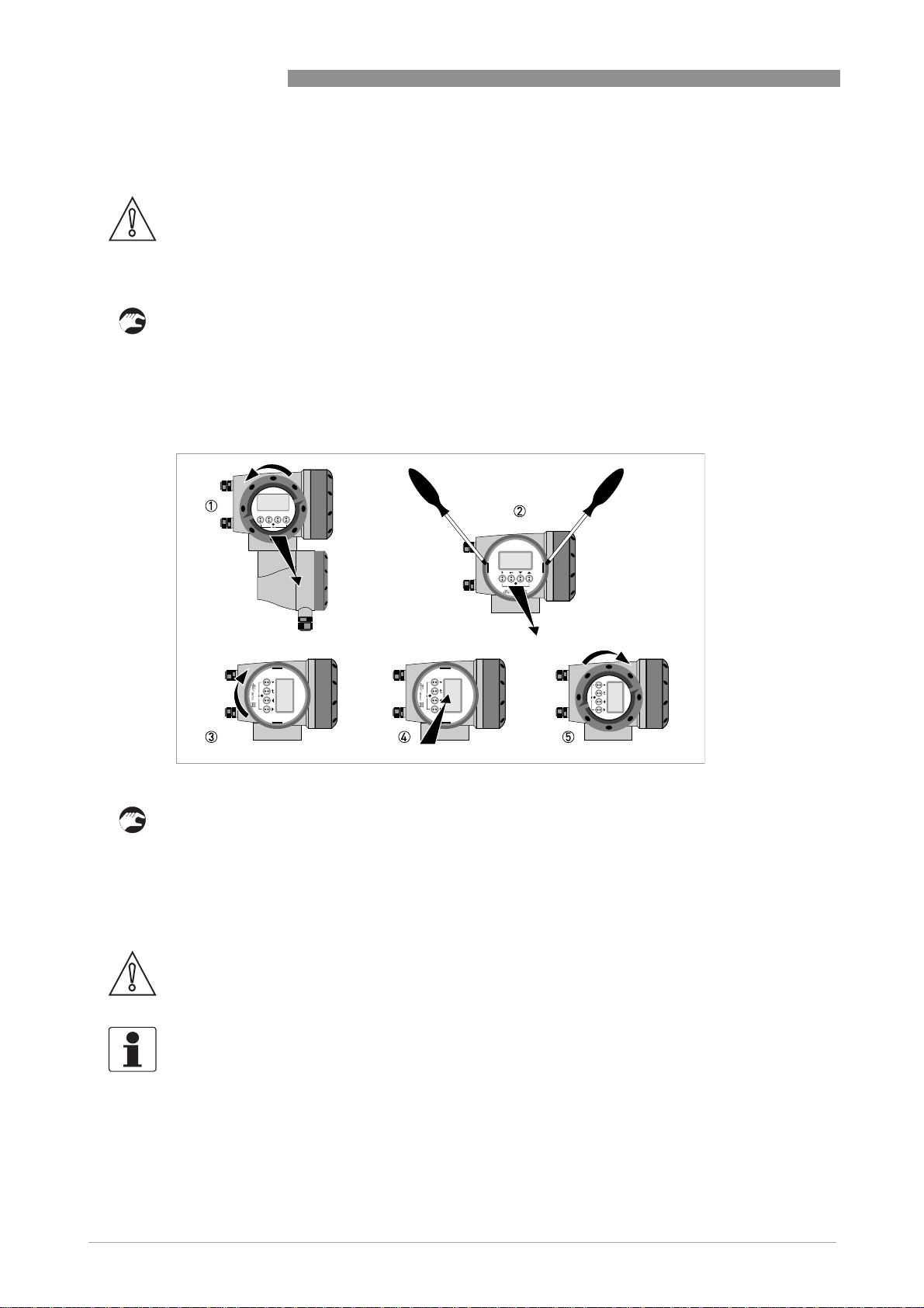
Figure 1-14: Turning the display of the field housing version
The display of the field housing version can be turned in 90° increments.
1 Unscrew the cover from the display and operation control unit.
2 Using a suitable tool, pull out the two metal puller devices to the left and right of the display.
3 Pull out the display between the two metal puller devices and rotate it to the required position.
4 Slide the display and then the metal puller devices back into the housing.
5 Re-fit the cover and tighten it by hand.
CAUTION!
The ribbon cable of the display must not be folded or twisted repeatedly.
INFORMATION!
Each time a housing cover is opened, the thread should be cleaned and greased. Use only resinfree and acid-free grease.
Ensure that the housing gasket is properly fitted, clean and undamaged.
16
www.krohne.com 07/2009 - 7.30959.24.00 - QS OPTISONIC 6300 R04 en
Page 17

OPTISONIC 6300
1.9.3 Mounting of UFC 300 W
Perform the following procedures:
• Remove aluminium mounting plate from rear of the signal converter, and attach to wall or
standpipe.
• Mount signal converter.
• Position lock washers and nuts on the housing bolts, tighten nuts slightly.
• Align housing, tighten nuts firmly.
• Observe max. allowed length of 30 m / 98.4 ft for the signal cable.
INSTALLATION 1
www.krohne.com07/2009 - 7.30959.24.00 - QS OPTISONIC 6300 R04 en
17
Page 18

2 ELECTRICAL CONNECTIONS
2.1 Safety instructions
DANGER!
All work on the electrical connections may only be carried out with the power disconnected. Take
note of the voltage data on the nameplate!
DANGER!
Observe the national regulations for electrical installations!
DANGER!
For devices used in hazardous areas, additional safety notes apply; please refer to the Ex
documentation.
WARNING!
Observe without fail the local occupational health and safety regulations. Any work done on the
electrical components of the measuring device may only be carried out by properly trained
specialists.
OPTISONIC 6300
INFORMATION!
Look at the device nameplate to ensure that the device is delivered according to your order.
Check for the correct supply voltage printed on the nameplate.
2.2 Construction of the various housing versions
2.2.1 UFC 300 F
The terminal compartments are accessible after unscrewing cover 2 and 6.
18
Figure 2-1: Construction (field version)
1 Cover, electronics compartment
2 Cover, terminal compartment for power supply and inputs/outputs
3 Cable entry for power
4 Cable entry for inputs/outputs
5 Cable entry for sensor cable
6 Cover, sensor terminal compartment
www.krohne.com 07/2009 - 7.30959.24.00 - QS OPTISONIC 6300 R04 en
Page 19

OPTISONIC 6300
2.2.2 UFC 300 W
The terminal compartments are accessible after opening cover 2.
Figure 2-2: Construction of remote version
1 Cover, electronics compartment
2 Cover for the three separate terminal compartments for power, sensor connection and inputs/outputs
3 Locking screw, 1/2 turn left/right to open/close cover 2
4 Sensor terminal compartment
5 Terminal compartment for inputs/outputs
6 Power terminal compartment, open separate shock-hazard protection cover
ELECTRICAL CONNECTIONS 2
www.krohne.com07/2009 - 7.30959.24.00 - QS OPTISONIC 6300 R04 en
19
Page 20

2 ELECTRICAL CONNECTIONS
2.3 Electrical connection
CAUTION!
To ensure smooth functioning, always use the signal cables included in the delivery.
The flow sensor is connected to the signal converter via the single signal cable.
2.3.1 Signal cable to flow sensor
Figure 2-3: Connecting the signal cable to the rail (small and medium version)
1 Connect the green cable to "DOWN"
2 Connect the blue cable to "UP"
3 Turn the screws clockwise to secure the cap
OPTISONIC 6300
20
Figure 2-4: Connect the signal cable in case of stainless steel / XT version.
1 Put in the connector.
2 Turn knob to secure the connector.
CAUTION!
For XT versions: check if the signal cable is heat protected with the protection sleeve of 1 meter /
40".
www.krohne.com 07/2009 - 7.30959.24.00 - QS OPTISONIC 6300 R04 en
Page 21

OPTISONIC 6300
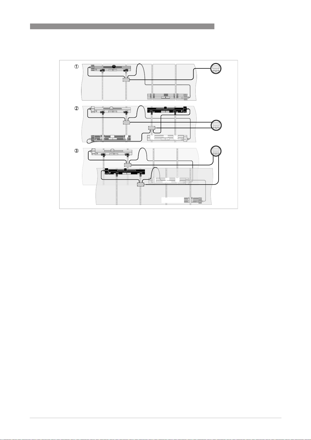
Figure 2-5: Connections in cable box (large version)
1 Connect the blue cable to the UP rail.
2 Connect the green cable to the DOWN rail.
3 Make connections in cable box.
4 Cable to converter
5 Turn the screws clockwise to secure the caps.
ELECTRICAL CONNECTIONS 2
www.krohne.com07/2009 - 7.30959.24.00 - QS OPTISONIC 6300 R04 en
21
Page 22

2 ELECTRICAL CONNECTIONS
2.3.2 Signal cable and power supply signal converter
INFORMATION!
The power terminals in the terminal compartments are equipped with additional hinged lids to
prevent accidental contact.
DANGER!
The device must be grounded in accordance with regulations in order to protect personnel
against electric shocks.
OPTISONIC 6300
Figure 2-6: Construction of wall version
1 Connect blue cable to 1U (to 2U for 2
2 Communication I/O
3 Power supply: 24 VAC/DC or 100...240 VAC
nd
sensor) and the green cable to 1D (2D for 2nd sensor)
22
www.krohne.com 07/2009 - 7.30959.24.00 - QS OPTISONIC 6300 R04 en
Page 23

OPTISONIC 6300
Figure 2-7: Construction (field version)
1 Cover, electronics compartment
2 Cover, terminal compartment for power supply and inputs/outputs
3 Cable entry for power
4 Cable entry for inputs/outputs
5 Cable entry for sensor cable
6 Cover, sensor terminal compartment
ELECTRICAL CONNECTIONS 2
100…230 VAC (-15% / +10%)
• Connect the protective ground conductor PE of the mains power supply to the separate
terminal in the terminal compartment of the signal converter.
• Connect the live conductor to the L terminal and the neutral conductor to the N terminal.
24 VAC/DC (-15% / +10%)
• For reasons to do with the measurement process, connect a functional ground FE to the
separate U-clamp terminal in the terminal compartment of the signal converter.
• When connecting to functional extra-low voltages, provide a facility for protective separation
(PELV) (VDE 0100 / VDE 0106 and/or IEC 364 / IEC 536 or relevant national regulations).
www.krohne.com07/2009 - 7.30959.24.00 - QS OPTISONIC 6300 R04 en
23
Page 24

2 ELECTRICAL CONNECTIONS
2.3.3 Signal cable to converter
CAUTION!
Connect coax cables and follow indications up/down (1U 1D; 2U 2D; 3U 3D).
Figure 2-8: Connect signal cable (field version)
OPTISONIC 6300
Figure 2-9: Connect signal cable (wall-mounted version)
2.3.4 Laying electrical cables correctly
Figure 2-10: Protect housing from dust and water
1 Lay the cable in a loop just before the housing.
2 Tighten the screw connection of the cable entry securely.
3 Never mount the housing with the cable entries facing upwards.
4 Seal cable entries that are not needed with a plug.
24
www.krohne.com 07/2009 - 7.30959.24.00 - QS OPTISONIC 6300 R04 en
Page 25

OPTISONIC 6300
2.4 Inputs and outputs, overview
2.4.1 Fixed, non-alterable input/output versions
This measuring transducer is available with various input/output combinations.
CG-No. Connection terminals
A+ A A- B B- C C- D D-
Basic input/output (I/O) standard
1 0 0
Ia + HART® active 1
Ip + HART® passive 1
EEx-i inputs/outputs (I/Os) option
2 0 0
3 0 0
2 1 0 Ia active PN / SNNAMUR
3 1 0 Ia active PN / SNNAMUR
2 2 0 Ip passive PN / SNNAMUR
3 2 0 Ip passive PN / SNNAMUR
1 function changed by reconnection
2 changeable
Sp / Cp passive 2 Sp passive Pp / Sp passive 2
passive 2
C
p
Cp passive 2
passive 2
C
p
Cp passive 2
ELECTRICAL CONNECTIONS 2
Ia + HART® active
Ip + HART® passive
Ia + HART® active
Ip + HART® passive
Ia + HART® active
Ip + HART® passive
PN / SN NAMUR 2
PN / SN NAMUR 2
PN / SN NAMUR 2
PN / SN NAMUR 2
PN / SNNAMUR 2
PN / SNNAMUR 2
• The grey boxes in the tables denote unassigned or unused connection terminals.
• Connection terminal A+ is only operable in the basic input/output version.
www.krohne.com07/2009 - 7.30959.24.00 - QS OPTISONIC 6300 R04 en
25
Page 26

2 ELECTRICAL CONNECTIONS
Description of abbreviations and CG identifier for possible optional modules
on terminals A and B
Abbreviation Identifier for CG No. Description
OPTISONIC 6300
I
a
I
p
Pa / S
Pp / S
PN / S
C
a
C
p
C
N
a
p
N
A
B
Active current output (including HART = HART® capability)
Passive current output (including HART = HART® capability)
C Active pulse, frequency, status output or limit switch (changeable)
E Passive pulse, frequency, status output or limit switch (changeable)
F Passive pulse, frequency, status output or limit switch according to
NAMUR (changeable)
G Active control input
K Passive control input
H Active control input to NAMUR
Signal converter monitors cable breaks and short circuits as per EN
60947-5-6. Errors indicated on LCD display. Error messages possible via
status output.
IIn
IIn
a
p
P Active current input
R Passive current input
- 8 No additional module installed
- 0 No further module possible
26
www.krohne.com 07/2009 - 7.30959.24.00 - QS OPTISONIC 6300 R04 en
Page 27

OPTISONIC 6300
2.4.2 Alterable input/output versions
The signal converter is available with various input/output combinations.
CG-No. Connection terminals
A+ A A- B B- C C- D D-
Modular inputs/outputs option
4 _ _ max. 2 option modules for term. A + B
8 _ _ max. 2 option modules for term. A + B
6 _ _ max. 2 option modules for term. A + B
B _ _ max. 2 option modules for term. A + B
7 _ _ max. 2 option modules for term. A + B
C _ _ max. 2 option modules for term. A + B
1 changeable
ELECTRICAL CONNECTIONS 2
Ia + HART® active
Ip + HART® passive
Ia + HART® active
Ip + HART® passive
Ia + HART® active
Ip + HART® passive
Pa / Sa active 1
Pa / Sa active 1
Pp / Sp passive 1
Pp / Sp passive 1
PN / SN NAMUR 1
PN / SN NAMUR 1
Description of abbreviations and CG identifier for possible optional modules
on terminals A and B
Abbreviation Identifier for CG No. Description
I
a
I
p
Pa / S
a
Pp / S
p
PN / S
N
C
a
C
p
C
N
IIn
a
IIn
p
- 8 No additional module installed
- 0 No further module possible
A
B
Active current output (including HART = HART® capability)
Passive current output (including HART = HART® capability)
C Active pulse, frequency, status output or limit switch (changeable)
E Passive pulse, frequency, status output or limit switch (changeable)
F Passive pulse, frequency, status output or limit switch according to
NAMUR (changeable)
G Active control input
K Passive control input
H Active control input to NAMUR
Signal converter monitors cable breaks and short circuits as per EN
60947-5-6. Errors indicated on LCD display. Error messages possible via
status output.
P Active current input
R Passive current input
www.krohne.com07/2009 - 7.30959.24.00 - QS OPTISONIC 6300 R04 en
27
Page 28

3 START-UP
3.1 General instructions for programming
Human machine interface (HMI)
Human machine interface (HMI)
Human machine interface (HMI)Human machine interface (HMI)
OPTISONIC 6300
Figure 3-1: Display and operating elements (Example: flow indication with 2 measuring values)
1 Indicates a possible status message in the status list
2 Tag number (is only indicated if this number was entered previously by the operator)
3 Indicates when a key has been pressed
4 1st measured variable in large depiction
5 Bargraph indication
6 Keys (see table below for function and depiction in text)
7 Interface to the GDC bus (not present in all signal converter versions)
8 Infrared sensor (not present in all signal converter versions)
Key Measuring mode Menu mode Sub-menu or function
mode
> Switch from measuring
mode to menu mode;
press key for 2.5 s,
"quick start" menu is
then displayed
^ - Return to measuring
↓ or ↑ Switch between display
pages: measured
value 1 + 2, trend page
and status page(s)
Esc (> + ↑) - - Return to menu mode
Access to displayed
menu, then 1st
submenu is displayed
mode but first ask
whether the data should
be saved
Select menu Select sub-menu or
Access to displayed submenu or function
Press 1 to 3 times,
return to menu mode,
data saved
function
without acceptance of
data
Parameter and data
mode
For numerical values,
move cursor
(highlighted in blue) one
position to the right
Return to sub-menu or
function, data saved
Use cursor highlighted
in blue to change
number, unit, setting
and to move the decimal
point
Return to sub-menu or
function without
acceptance of data
28
www.krohne.com 07/2009 - 7.30959.24.00 - QS OPTISONIC 6300 R04 en
Page 29

OPTISONIC 6300
Start installation menu
Start installation menu
Start installation menuStart installation menu
• Connect converter to power supply and power up converter.
First and second page appear intermittently
• Keep left button ">" pressed, until in display appears "release key now".
START-UP 3
www.krohne.com07/2009 - 7.30959.24.00 - QS OPTISONIC 6300 R04 en
29
Page 30

3 START-UP
Installation menu
Installation menu
Installation menuInstallation menu
CAUTION!
•
If you program the diameter, use the outer diameter of the pipe.
•
For improved accuracy fill in as much details as possible.
•
Fill in the actual transducer distance at menu X9.7
•
Run the optimization loop until the transducer distance changes no more than 0.5%.
• > ↓↑^
X1...X7
X1 language > select from list using ↑ ↓ > ^
X2 GDC IR interface > activate / cancel ^
X3 units > X3.1, X3.2, … ↑ ↓
X4 number of pipes > 1 pipe / 2 pipes ↑ ↓ ^
(X5 becomes active if one pipe
(X5 becomes active if one pipe is selected in X4)
(X5 becomes active if one pipe(X5 becomes active if one pipe
X5 number of paths > 1 path / 2 paths ↑ ↓ ^
(underneath X6 becomes active if one pipe
(underneath X6 becomes active if one pipe is selected in X4)
(underneath X6 becomes active if one pipe(underneath X6 becomes active if one pipe
(Note: the measurement results of path 1 and path 2
(Note: the measurement results of path 1 and path 2 are averaged !)
(Note: the measurement results of path 1 and path 2(Note: the measurement results of path 1 and path 2
(underneath X6 and X7 become active if two pipes
(underneath X6 and X7 become active if two pipes are selected in X4)
(underneath X6 and X7 become active if two pipes(underneath X6 and X7 become active if two pipes
X6 pipe data / pipe data 1 > X6.2, X6.3, … ↑ ↓
X7 pipe data 2 > ↑ ↓
OPTISONIC 6300
X3.1 size > select from list using ↑ ↓ > ^
X3.2 volume flow > select from list using ↑ ↓ > ^
X3.3 velocity > select from list using ↑ ↓ > ^
X3.4 density > select from list using ↑ ↓ > ^
X3.5 viscosity > select from list using ↑ ↓ > ^
X6.2 pipe tag > fill in 12 pos using ↑ ↓ > ^
X6.3 diameter > fill in using ↑ ↓ > ^
X6.4 pipe material > select from list using ↑ ↓ > ^
X6.5 VoS pipe material > read advise or fill in using ↑
↓ >
X6.6 wall thickness > fill in using ↑ ↓ > ^
X6.7 liner material > select from list using ↑ ↓ > ^
X6.8 VoS liner material > read advise or fill in using ↑
↓ >
X6.9 liner thickness > fill in using ↑ ↓ > ^
X6.10 fluid > select from list using ↑ ↓ > ^
X6.11 VoS fluid > read advise or fill in using ↑
↓ >
X6.12 density > read advise or fill in using ↑
↓ >
X6.13 viscosity > fill in using ↑ ↓ > ^
X7.1 copy pipe 1 data > start to copy ? ↑ ↓
^
^
^
^
30
www.krohne.com 07/2009 - 7.30959.24.00 - QS OPTISONIC 6300 R04 en
Page 31

OPTISONIC 6300
X9...X10
X9 install transd. 1 > X9.1, X9.2,… ↑ ↓
(underneath X10 becomes active if two pipes or two paths
(underneath X10 becomes active if two pipes or two paths are selected in X4 or X5)
(underneath X10 becomes active if two pipes or two paths(underneath X10 becomes active if two pipes or two paths
X10 install transd. 2 > ↑ ↓
START-UP 3
if no:
if no: copy pipe 1 data appears
if no:if no:
if yes:
if yes: copy pipe 1 data appears
if yes: if yes:
X9.1 transducer set > read preset Ta,Tb,Tc /
X9.2 calibration number read ^
X9.3 number of
traverses
X9.4 mount transducers
at
please wait: decounting 30 seconds
X9.5 act. flow,
preliminary
X9.6 check signal read (0 - 100 %) ^
X9.7 actual distance > fill in using ↑ ↓ > ^
(start optimization loop)
X9.8.1 optimize distance ? yes/no ^
X9.8.2 act. VoS fluid read ^
X9.8.3 continue ? yes/no ^
X9.8.4 VoS fluid read / confirm or overrule
X9.8.5 mount transducers
at
(end optimization loop; next menu appearing is X9.8.1)
confirm or overrule using ↑ ↓
>
> read preset 1,2,4 / confirm or
overrule using ↑ ↓ >
read advise ^
read ^
if no: go to X9.9
if yes: continue with X9.8.2
if no: go to X9.9
if yes: continue with X9.8.4
using ↑ ↓ >
read advise ^
submenus identical to X9.1
up to X9.12
Go to X7
Fill in menu X7.2 up to X7.13:
is similar to X6.2 up to X6.13
after copy process
^
^
^
^
www.krohne.com07/2009 - 7.30959.24.00 - QS OPTISONIC 6300 R04 en
31
Page 32

3 START-UP
3.2 Start measurement of small / medium version
• Power up the converter (do not mount and/or connect the rails yet)
• Fill in menu X1...X7 (see section "Installation menu" in chapter "General instructions for
programming")
• X9.1: Check the reading with the sensor code (Ta/Tb) on rail. Press enter
• X9.2: Check the reading with the calibration number on the nameplate. Press enter
• X9.3: Check the factory preset number of traverses (default: 2, for DN<25: 4)
• X9.4: Read the advised mounting distance and position the transducer at that distance . Press
enter
• X9.5: Read the preliminary volume flow. Press enter
• X9.6: Read the actual signal strength
INFORMATION!
Advice on signal strength:
Advice on signal strength:
Advice on signal strength:Advice on signal strength:
Signal > 75%:
Signal > 75%: good signal, optimization loop not needed
Signal > 75%:Signal > 75%:
Signal 50...75%:
Signal 50...75%: fairly good signal, optimization loop can improve the signal
Signal 50...75%:Signal 50...75%:
Signal 10...50%:
Signal 10...50%: low signal, optimization loop needed
Signal 10...50%:Signal 10...50%:
Signal < 10%:
Signal < 10%: bad or no signal, check settings in menu X6, increase transducer distance and/or
Signal < 10%:Signal < 10%:
go into the optimization loop.
OPTISONIC 6300
• X9.7: Confirm or adjust the reading with the actual distance on the rail.
• X9.8: Optimization loop. Repeat steps X9.8.1...X9.8.5 until the advised mounting distance does
not change more than 0.5%.
• X9.8.1: Optimise distance?
• X9.8.2: Read the velocity of sound of the fluid
• X9.8.3: Continue?
• X9.8.4: Confirm or adjust the velocity of sound
• X9.8.5: Read the advised mounting distance and reposition the transducer
• X9.9: Read the preliminary volume flow
• X9.10: Path ready? Enter "Yes". If you have:
1 path or pipe: you are finished, proceed with X9.12
nd
2 paths: go to X9 for the 2
2 pipes: go to X10 for the 2
• X9.12: End Installation? Enter "Yes" to save the installation. The measurement screen will
appear.
• Mount the cover (see the section "mounting the cover" in chapter "General mechanical
installation")
path
nd
pipe
32
www.krohne.com 07/2009 - 7.30959.24.00 - QS OPTISONIC 6300 R04 en
Page 33

OPTISONIC 6300
3.3 Start measurement of large version
Prepare installation
Prepare installation
Prepare installationPrepare installation
START-UP 3
Figure 3-2: Procedure for installation of large version
1 Enter the values for the installation menu, X1...X9.8.4
2 Read the advised mounting distance in menu X9.8.5
3 Choose for Z-mode (default) or ...
4 Choose for V-mode
5 Finish the installation menu
• Power up the converter (do not mount and/or connect the rails yet)
• Fill in menu X1...X7 as described in section "Installation menu" in chapter "General
instructions for programming". Select "1 path" initially in X5
• X9.1: Check the reading with the sensor code (Ta/Tb) on rail
• X9.2: Check the reading with the calibration number on the nameplate
• X9.3: Check the factory preset number of traverses (default: 1 for Z-mode)
• X9.4: Read the advised mounting distance. Write it down, you need it later
• X9.5: Press enter
• X9.6: Press enter. Wait for 30 seconds
• X9.7: Press enter
• X9.8: Optimization loop. Enter "No" in X9.8.1
• X9.9: Press enter. Wait for 30 seconds
• X9.10: Path ready? Enter "Yes"
• X9.12: End Installation? Enter "Yes"
www.krohne.com07/2009 - 7.30959.24.00 - QS OPTISONIC 6300 R04 en
33
Page 34

3 START-UP
CAUTION!
Choose between Z and V mode before you proceed. The Advised Distance (menu X9.4) must be >
246 mm / 9,7" for V-mode.
Set transducer positions for both rails according to the table below.
Advised distance [mm]
Advised distance [mm] Transducer position [mm]
Advised distance [mm]Advised distance [mm]
100...250 -65
>250 0
Transducer position [mm]
Transducer position [mm]Transducer position [mm]
OPTISONIC 6300
34
Figure 3-3: Device versions
1 Single pipe, single path
2 Single pipe, dual path
3 Dual pipe
www.krohne.com 07/2009 - 7.30959.24.00 - QS OPTISONIC 6300 R04 en
Page 35

OPTISONIC 6300
3.4 Mechanical installation for large version
INFORMATION!
You need a calculator, measuring band and pen & paper to install a large version.
Mounting the UP rail
Mounting the UP rail
Mounting the UP railMounting the UP rail
CAUTION!
Make sure that you mount the rail parallel to the pipe. Mount the fixing units and the cable box as
shown below.
START-UP 3
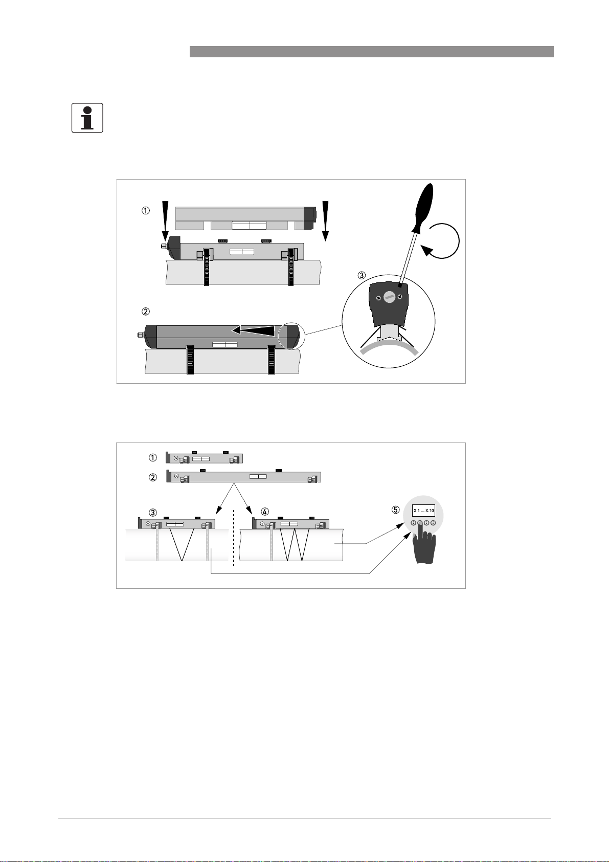
Figure 3-4: Mounting the large rail
1 Align the UP rail with the pipeline.
2 Fixing units
3 Turn screws clockwise to secure.
4 Mark the position.
5 Cable box
www.krohne.com07/2009 - 7.30959.24.00 - QS OPTISONIC 6300 R04 en
35
Page 36

3 START-UP
OPTISONIC 6300
36
Figure 3-5: Mounting large version rail
1 Pull the metal strap through the upper slit of the UP rail.
2 Take the metal strap around the pipe (45...60°).
3 Push the end of the metal strap in the lower slit of the fixing unit.
4 Take the other side of the metal strap around the pipe to the fixing unit.
5 Mount the cable box (only for downstream metal strap).
6 Push the metal strap through the upper slit of the fixing unit.
7 Pull the metal strap moderately tight by hand.
• Secure by turning screws clockwise.
www.krohne.com 07/2009 - 7.30959.24.00 - QS OPTISONIC 6300 R04 en
Page 37

OPTISONIC 6300
Mounting the DOWN rail in Z-mode
Mounting the DOWN rail in Z-mode
Mounting the DOWN rail in Z-modeMounting the DOWN rail in Z-mode
Set transducer positions for both rails according to the table below.
Advised distance [mm]
Advised distance [mm] Transducer position [mm]
Advised distance [mm]Advised distance [mm]
100...250 -65
>250 0
Measure the outer diameter of the pipe with a measuring band.
For Z-mode, you must install the DOWN rail at the opposite location at the pipe. There are two
possible ways to find the exact location:
1. FIND THE LOCATION WITH A FIXED REFERENCE POINT
Calculate the half of the outer diameter. Mark this 180° alignment line on the pipe.
Transducer position [mm]
Transducer position [mm]Transducer position [mm]
START-UP 3
Figure 3-6: Find the opposite location with a reference point
1 Measure the distance between the transducer of the UP rail and the reference point.
2 Add the Advised Distance and mark the location on the alignment line.
• Mount the DOWN rail in such a way that the transducer is at the marked location.
2. FIND THE LOCATION WITH THE SUPPLIED POSITIONING TOOL
www.krohne.com07/2009 - 7.30959.24.00 - QS OPTISONIC 6300 R04 en
37
Page 38

3 START-UP
Mount the positioning tool to the UP rail as shown.
OPTISONIC 6300
1 Mark the cables at a distance of 1.63 x outer diameter.
2 Outer diameter of pipeline
INFORMATION!
For large diameters you can use the weight of the metal plates to throw the cable around the
pipe. First release one of the cables in that case!
38
www.krohne.com 07/2009 - 7.30959.24.00 - QS OPTISONIC 6300 R04 en
Page 39

OPTISONIC 6300
Figure 3-7: Mark the pipelines with the V-mark
Pull the V-shaped plate in the downstream direction as much as possible. Pay attention that the cables are not obstructed.
Put the two V-marks on the pipeline.
Do the same in the upstream direction.
CAUTION!
Repeat above steps to check if you find the same points.
START-UP 3
Figure 3-8: Marking the opposite location
Calculate the middle of the alignment line between the 4 V-marks as shown.
www.krohne.com07/2009 - 7.30959.24.00 - QS OPTISONIC 6300 R04 en
39
Page 40

3 START-UP
Figure 3-9: Finding the location for the DOWN rail
1 Advised Distance as shown in menu X9.4
2 Measure the distance between the transducer and the end of the UP rail.
3 Determine and mark the location of the transducer of the DOWN rail: 3333 = 1111 - 2222
• Mount the DOWN rail in such a way that the transducer is at the marked location.
• Grease all transducers, see "General mechanical installation".
INFORMATION!
It can be necessary to install the DOWN rail as shown below.
OPTISONIC 6300
40
www.krohne.com 07/2009 - 7.30959.24.00 - QS OPTISONIC 6300 R04 en
Page 41

OPTISONIC 6300
Mounting the DOWN rail in V-mode
Mounting the DOWN rail in V-mode
Mounting the DOWN rail in V-modeMounting the DOWN rail in V-mode
For V-mode, you must install the DOWN rail in line with the UP rail. It is easier to install than the
Z-mode, but you need more free pipe length. V-mode is possible for DN450/600...2000 (minimum
depends on application).
START-UP 3
Figure 3-10: Mounting large version in V-mode
1 Fixing units
2 Reference marking
3 Cable box
4 Advised Distance, X9.4
5 Minimum distance between UP and DOWN rail: 110 mm / 4.3"
www.krohne.com07/2009 - 7.30959.24.00 - QS OPTISONIC 6300 R04 en
41
Page 42

3 START-UP
Electrical connections
Electrical connections
Electrical connectionsElectrical connections
Figure 3-11: Connections in cable box (large version)
1 Connect the blue cable to the UP rail.
2 Connect the green cable to the DOWN rail.
3 Make connections in cable box.
4 Cable to converter
5 Turn the screws clockwise to secure the caps.
OPTISONIC 6300
42
Figure 3-12: Construction of wall version
nd
1 Connect blue cable to 1U (to 2U for 2
2 Communication I/O
3 Power supply: 24 VAC/DC or 100...240 VAC
sensor) and the green cable to 1D (2D for 2nd sensor)
www.krohne.com 07/2009 - 7.30959.24.00 - QS OPTISONIC 6300 R04 en
Page 43

OPTISONIC 6300
Figure 3-13: Construction (field version)
1 Cover, electronics compartment
2 Cover, terminal compartment for power supply and inputs/outputs
3 Cable entry for power
4 Cable entry for inputs/outputs
5 Cable entry for sensor cable
6 Cover, sensor terminal compartment
START-UP 3
INFORMATION!
See also the section "Installation menu" in chapter "General instructions for programming".
• Go through menu X1...X7 as described in section "Installation menu" in chapter "General
instructions for programming". Correct X5 if needed.
• X9.1: Press enter
• X9.2: Press enter
• X9.3: Press enter
• X9.4: Press enter
• X9.5: Read the preliminary volume flow. Press enter
• X9.6: Check signal
CAUTION!
Advice on signal strength:
Advice on signal strength:
Advice on signal strength:Advice on signal strength:
Signal > 75%:
Signal > 75%: good signal, optimization loop not needed
Signal > 75%:Signal > 75%:
Signal 50...75%:
Signal 50...75%: fairly good signal, optimization loop can improve the signal
Signal 50...75%:Signal 50...75%:
Signal 10...50%:
Signal 10...50%: low signal, optimization loop needed
Signal 10...50%:Signal 10...50%:
Signal < 10%:
Signal < 10%: bad or no signal, check settings in menu X6, increase transducer distance and/or
Signal < 10%:Signal < 10%:
go into the optimization loop.
www.krohne.com07/2009 - 7.30959.24.00 - QS OPTISONIC 6300 R04 en
43
Page 44

3 START-UP
• X9.7: Confirm or adjust the reading with the actual distance on the rail.
• X9.8: Optimization loop. Repeat steps X9.8.1...X9.8.5 until the advised mounting distance does
not change more than 0.5%.
• X9.8.1: Optimise distance?
• X9.8.2: Read the velocity of sound of the fluid
• X9.8.3: Continue?
• X9.8.4: Confirm or adjust the velocity of sound
• X9.8.5: Read the advised mounting distance and reposition the transducer
• X9.9: Read the preliminary volume flow
• X9.10: Path ready? Enter "Yes". If you have:
1 path or pipe: you are finished, proceed with X9.12
2 paths: go to X9 for the 2
2 pipes: go to X10 for the 2
• X9.12: End Installation? If you enter "No" the installation is not saved, go to X9. If you enter
"Yes" the installation is saved and the measurement screen will appear.
• Mount the cover (see section "mounting the cover" in chapter "General mechanical
installation")
nd
nd
OPTISONIC 6300
path
pipe
44
www.krohne.com 07/2009 - 7.30959.24.00 - QS OPTISONIC 6300 R04 en
Page 45

OPTISONIC 6300
4.1 Technical data
INFORMATION!
•
The following data is provided for general applications. If you require data that is more
relevant to your specific application, please contact us or your local representative.
•
Additional information (certificates, special tools, software,...) and complete product
documentation can be downloaded free of charge from the website (Downloadcenter).
Measuring system
Measuring principle Ultrasonic transit time
Application range Flow measurement of liquids
Measured value
Measured value
Measured valueMeasured value
Primary measured value Transit time
Secondary measured value Volume flow, mass flow, flow speed, flow direction, speed of sound,
TECHNICAL DATA 4
gain, signal to noise ratio, diagnosis value, reliability of flow
measurement, quality of acoustic signal
Design
The measurement system consists of a measuring sensor and a
signal converter. It is only available as separate version.
Signal converter
Signal converter
Signal converterSignal converter
Wall-mounted housing (W) remote version
Field housing (F) - remote
version
Measuring sensor
Measuring sensor
Measuring sensorMeasuring sensor
Standard Small, medium or large version in aluminum
Optional Small / medium stainless steel version
Diameter ranges
Diameter ranges
Diameter rangesDiameter ranges
Small DN15...100 / ½…4"
Medium DN50...400 / 2…16"
Large DN200...4000 / 8…160"
Options
Options
OptionsOptions
Inputs / outputs
Counters 2 internal counters with a max. of 8 counter places (e.g. for counting
Self diagnostics Integrated verification, diagnosis functions: flowmeter, process,
UFC 300 W (general purpose)
UFC 300 F (Option: Ex version)
Small / medium XT (eXtended Temperature).
Outer diameter must be at least 20 mm / 0.79".
Outer diameter must be smaller than 4300 mm / 169.29".
Current (incl. HART®), pulse, frequency and/or status output, limit
switch and/or control input (depending on the I/O version)
volume and/or mass units)
measured value, empty pipe detection, bargraph
www.krohne.com07/2009 - 7.30959.24.00 - QS OPTISONIC 6300 R04 en
45
Page 46

4 TECHNICAL DATA
Display and user interface
Display and user interface
Display and user interfaceDisplay and user interface
Graphic display LC display, backlit white
Operator input elements 4 optical keys for operator control of the signal converter without
Remote control
Display functions
Display functions
Display functionsDisplay functions
Menu Programming of parameters at 2 measured value pages, 1 status
Language of display texts English, French, German
Units Metric, British and US units selectable from list / free unit
OPTISONIC 6300
Size: 128x64 pixels, corresponds to 59x31 mm = 2.32"x1.22"
Display turnable in 90° steps
The readability of the display could be reduced at ambient
temperatures below -25°C / -13°F.
opening the housing.
Option: Infrared interface (GDC)
PACTware® including Device Type Manager (DTM)
All DTM's and drivers are available at the internet homepage of the
manufacturer.
page, 1 graphic page (measured values and descriptions adjustable
as required)
Measuring accuracy
Reference conditions Medium: water
Temperature: 20°C / 68°F
Straight inlet section: 10 DN
Maximum measuring error ±1% of the measured value
Repeatability <±0.2%
for DN≥50 mm / 2" and v > 0.5 m/s / 1.5 ft/s
±3% of the measured value
for DN<50 mm / 2" and v > 0.5 m/s / 1.5 ft/s
Operating conditions
Temperature
Temperature
TemperatureTemperature
Process temperature Standard version: -40...+120°C / -40...+248°F
XT version: -40...+200°C / -40...+392°F
Ambient temperature Sensor: -40...+70°C / -40...+158°F
Signal converter: -40…+60°C / -40…+140°F
(ambient temperature 55°C / 131°F and higher: protect electronics
against self-heating, because an increase in the electronics
temperature in 10°C/50°F steps leads to a corresponding reduction
of the electronics' service life by a factor of two).
Storage temperature -50…+70°C / -58…+158°F
Pipe specifications
Pipe specifications
Pipe specificationsPipe specifications
Material Metal, plastic, ceramic, asbestos cement, internal / external coated
Pipewall thickness < 200 mm / 7.87"
Liner thickness < 20 mm / 0.79"
pipes (coatings and liners fully bonded to pipe wall)
46
www.krohne.com 07/2009 - 7.30959.24.00 - QS OPTISONIC 6300 R04 en
Page 47

OPTISONIC 6300
Media properties
Media properties
Media propertiesMedia properties
Physical condition Liquids
Viscosity < 100 cSt (general guideline)
Permissible gas content (volume) ≤ 2%
Permissible solid content
(volume)
Recommended flow velocity 0.5...20 m/s
Other conditions
Other conditions
Other conditionsOther conditions
Protection category acc. to
IEC 529 / EN 60529
Vibration resistance IEC 68-2-64
Shock resistance IEC 60068-2-27
TECHNICAL DATA 4
For detailed information please contact your local representative.
≤ 5%
W (Wall) version signal converter:
IP 65 (acc. to NEMA 4/4x)
F (Field) version signal converter:
IP 66/67 (acc. to NEMA 4x/6)
All sensors:
IP 67 (acc. to NEMA 6)
Installation condititions
Measurement configuration Single path, single pipe or dual path / dual pipe
Inlet run ≥ 10 DN straight length
Outlet run ≥ 5 DN straight length
Dimensions and weights See chapter "Dimensions and weights"
Materials
Sensor Standard
Converter Standard
Standard
StandardStandard
Anodised aluminum
Option stainless steel / eXtended Temperature (small / medium
Option stainless steel / eXtended Temperature (small / medium
Option stainless steel / eXtended Temperature (small / medium Option stainless steel / eXtended Temperature (small / medium
version)
version)
version)version)
Rail construction: 1.4404 (AISI 316L)
Cable connection:1.4404, PSU with FKM O-ring
Standard
StandardStandard
F version: die-cast aluminum, polyurethane coated
W version: polyamide-polycarbonate
Option
Option
OptionOption
F version: stainless steel 316 L (1.4408)
Electrical connections
Voltage Standard: 100…230 VAC (-15% / +10%), 50/60 Hz
Option: 24 VAC/DC (AC: -15% / +10%; DC: -25% / +30%)
Power consumption AC: 22 VA
DC: 12 W
Signal cable double shielded, 2 internal triax, available lengths:
5 m / 15 ft (standard), maximum length 30 m / 90 ft
Cable entries Standard: M20 x 1.5
Option: ½" NPT, PF ½
www.krohne.com07/2009 - 7.30959.24.00 - QS OPTISONIC 6300 R04 en
47
Page 48

4 TECHNICAL DATA
Inputs and outputs
General All in- and outputs are galvanically isolated from each other and from
Description of used abbreviations U
Current output
Current output
Current outputCurrent output
Output data
Settings
Operating data Basic I/Os
Active U
Passive U
®
HART
HART
HARTHART
Description
OPTISONIC 6300
all other circuits
= external voltage; RL = load + resistance; Uo = terminal voltage;
ext
= nominal current
I
nom
Measurement of volume and mass (at constant density), HART®
communication
Without HART
Without HART
Without HARTWithout HART
Q = 0%: 0…20 mA; Q = 100%: 10…21.5 mA
Error identification: 0…22 mA
With HART
With HART
With HARTWith HART
Q = 0%: 4…20 mA; Q = 100%: 10…21.5 mA
Error identification: 3.5…22 mA
Basic I/Os Modular I/Os
Basic I/OsBasic I/Os
int,nom
I ≤ 22 mA
≤ 1kΩ
R
L
≤ 32 VDC
ext
I ≤ 22 mA
U0 ≥ 1.8 V at I = 22 mA
HART® protocol at active and passive current output
®
®
= 24 VDC
Modular I/Os Ex-i
Modular I/OsModular I/Os
Ex-i
Ex-iEx-i
U
int,nom
I ≤ 22 mA
R
L
U0 = 21 V
I0=90mA
P
0
C0= 90 nF /
L
0
C0= 110 nF /
L
0
U
ext
I ≤ 22 mA
U0 ≥ 4 V
R
L
UI= 30 V
II=100mA
P
I
CI=10nF
L
I
= 20 VDC
≤ 450 Ω
= 0.5W
=2mH
=0.5mH
≤ 32 VDC
≤(U
- Uo) / I
ext
=1W
~0mH
max
48
HART® version: V5
Universal HART® parameter fully integrated
Load ≥ 250 Ω
Please observe maximum value for current output
Multidrop Yes, current output = 4 mA
Multidrop addresses programmable in menu 1...15
Device drivers FDT/DTM
www.krohne.com 07/2009 - 7.30959.24.00 - QS OPTISONIC 6300 R04 en
Page 49

OPTISONIC 6300
Pulse or frequency output
Pulse or frequency output
Pulse or frequency outputPulse or frequency output
Output data Volume or mass counting
Function Can be set as a pulse output or frequency output
Settings For Q = 100%: 0.01...10000 pulses per second or pulses per unit
Operating data Basic I/Os
Active - U
Passive U
NAMUR - Passive to
TECHNICAL DATA 4
volume
Pulse width: setting automatic, symmetric or fixed (0.05...2000 ms)
Basic I/Os Modular I/Os
Basic I/OsBasic I/Os
≤ 32 VDC -
ext
ffff
≤ 100 Hz:
100 Hz:
100 Hz: 100 Hz:
max
max
maxmax
I ≤ 100 mA
open:
I ≤ 0.05 mA at U
ext
closed:
U
= 0.2 V at I ≤ 10 mA
0, max
= 2 V at I ≤ 100 mA
U
0, max
100 Hz < f
100 Hz < f
100 Hz < f100 Hz < f
≤ 10 kHz:
max
max
maxmax
10 kHz:
10 kHz: 10 kHz:
I ≤ 20 mA
open:
I ≤ 0.05 mA at U
ext
closed:
= 1.5 V at I ≤ 1mA
U
0, max
U
= 2.5 V at I ≤ 10 mA
0, max
= 5.0 V at I ≤ 20 mA
U
0, max
Modular I/Os Ex-i
Modular I/OsModular I/Os
= 24 VDC -
nom
ffff
≤ 100 Hz:
100 Hz:
100 Hz: 100 Hz:
max
max
maxmax
I ≤ 20 mA
open: I ≤ 0.05 mA
closed:
= 24 V at
U
0,nom
I=20mA
100 Hz < f
100 Hz < f
100 Hz < f100 Hz < f
kHz:
kHz:
kHz:kHz:
max
max
maxmax
≤ 10
I ≤ 20 mA
open: I ≤ 0.05 mA
closed:
= 22.5 V at
U
0,nom
I=1mA
= 21.5 V at
U
0,nom
I=10mA
U
= 19 V at
0,nom
I=20mA
= 32 VDC
=32VDC
EN 60947-5-6
open: I
closed: I
nom
nom
=0.6mA
=3.8mA
10
10 10
Ex-i
Ex-iEx-i
Passive to
EN 60947-5-6
open: I
closed: I
=0.43mA
nom
nom
UI = 30 V
= 100 mA
I
I
PI = 1 W
=10 nF
C
I
LI ~ 0 mH
=4.5mA
www.krohne.com07/2009 - 7.30959.24.00 - QS OPTISONIC 6300 R04 en
49
Page 50

4 TECHNICAL DATA
Status output / limit switch
Status output / limit switch
Status output / limit switchStatus output / limit switch
Function and settings Settable as automatic measuring range change, indicator for
Operating data Basic I/Os
Active - U
Passive U
NAMUR - Passive to
OPTISONIC 6300
direction of flow, overflow, error, operating point or empty pipe
detection
Valve control with activated dosing function
Status and/or control: ON or OFF
Basic I/Os Modular I/Os
Basic I/OsBasic I/Os
≤ 32 VDC
ext
I ≤ 100 mA
open:
I ≤ 0.05 mA at
=32VDC
U
ext
closed:
= 0.2 V at
U
0, max
I ≤ 10 mA
= 2 V at
U
0, max
I ≤ 100 mA
Modular I/Os Ex-i
Modular I/OsModular I/Os
= 24 VDC
int
Ex-i
Ex-iEx-i
-
I ≤ 20 mA
open: I ≤ 0.05 mA
closed:
U
= 24 V at
0, nom
I=20mA
U
= 32 VDC
ext
-
I ≤ 100 mA
= 47 kΩ
R
L, max
open:
I ≤ 0.05 mA at
U
=32VDC
ext
closed:
= 0.2 V at
U
0, max
I ≤ 10 mA
U
= 2 V at
0, max
I ≤ 100 mA
Passive to
EN 60947-5-6
open: I
closed: I
nom
nom
=0.6 mA
=3.8mA
EN 60947-5-6
open: I
closed: I
UI = 30 V
II = 100 mA
= 1 W
P
I
CI =10 nF
= 0 mH
L
I
=0.43mA
nom
nom
=4.5mA
50
www.krohne.com 07/2009 - 7.30959.24.00 - QS OPTISONIC 6300 R04 en
Page 51

OPTISONIC 6300
Control input
Control input
Control inputControl input
Function Hold value of the outputs (e.g. for cleaning work), set value of the
Operating data Basic I/Os
Active - U
Passive 8 V ≤ U
NAMUR - Active to EN 60947-5-
Low-flow cutoff
Low-flow cutoff
Low-flow cutoffLow-flow cutoff
On 0...±9.999 m/s; 0...20.0%, settable in 0.1% steps, separately for each
Off 0...±9.999 m/s; 0...19.0%, settable in 0.1% steps, separately for each
Time constant
Time constant
Time constantTime constant
Function Can be set together for all flow indicators and outputs, or separately
Time setting 0…100 seconds, settable in 0.1 second steps
TECHNICAL DATA 4
outputs to "zero", counter and error reset, range change.
Start of dosing when dosing function is activated.
Basic I/Os Modular I/Os
Basic I/OsBasic I/Os
≤ 32 VDC
ext
= 6.5 mA
I
max
at U
≤ 24 VDC
ext
= 8.2 mA
I
max
at U
≤ 32 VDC
ext
Contact closed (On):
≥ 8 V
U
0
with I
nom
=2.8mA
Contact open (Off):
≤ 2.5 V
U
0
with I
nom
=0.4mA
current and pulse output
current and pulse output
for: current, pulse and frequency output, and for limit switches and
the 3 internal counters
Modular I/Os Ex-i
Modular I/OsModular I/Os
= 24 VDC
int
Ex-i
Ex-iEx-i
-
Terminals open:
= 22 V
U
0, nom
Terminals bridged:
I
= 4 mA
nom
On:
≥ 12 V with
U
0
I
=1.9mA
nom
Off:
≤ 10 V with
U
0
I
=1.9mA
nom
3 V ≤ U
I
max
U
ext
I
max
U
ext
Contact closed (On):
U
0
with I
Contact open (Off):
U
0
with I
≤ 32 VDC
ext
= 9.5 mA at
≤ 24 V
= 9.5 mA at
≤ 32 V
≥ 3 V
=1.9mA
nom
≤ 2.5 V
=1.9mA
nom
U
ext
I ≤ 6 mA at U
I ≤ 6.6 mA at
U
ext
On:
U
0
Off:
U0 ≤ 3.5 V or
I ≤ 0.5 mA
UI = 30 V
= 100 mA
I
I
PI = 1 W
= 10 nF
C
I
LI = 0 mH
6
Contact open:
U
= 8.7 V
0, nom
Contact closed (On):
= 7.8 mA
I
nom
Contact open (off):
U
I
0, nom
= 1.9 mA
nom
= 6.3 V with
Identification for
open terminals:
U0 ≥ 8.1 V with
I ≤ 0.1 mA
Identification for
short circuited
terminals:
≤ 1.2 V with
U
0
I ≥ 6.7 mA
≤ 32 VDC
=24V
ext
=32V
≥ 5.5 V or I ≥ 4mA
www.krohne.com07/2009 - 7.30959.24.00 - QS OPTISONIC 6300 R04 en
51
Page 52

4 TECHNICAL DATA
Approvals and certificates
Hazardous areas
Hazardous areas
Hazardous areasHazardous areas
ATEX Sensor:
FM - Class I, DIV 1/2 Option (F version): approval ID = 3029326
CSA - GP / Class I,
DIV 1/2
Other approvals and standards
Other approvals and standards
Other approvals and standardsOther approvals and standards
Electromagnetic compatibility Directive: 89/336/EEC, NAMUR NE21/04
Low Voltage Directive Directive: 2006/95/EC
OPTISONIC 6300
Sensor:
Sensor:Sensor:
PTB 06 ATEX 2045 X
II 2 G Ex ia IIC T6...T4 (XT Version: II 2 G Ex ia IIC T6...T2)
Converter (F version only):
Converter (F version only):
Converter (F version only):Converter (F version only):
PTB 06 ATEX 2046 X
II 2(1) G Ex de [ia] IIC T6 or II 2 G Ex de [ia] IIC T6
II 2(1) G Ex d [ia] IIC T6 or II 2 G Ex d [ia] IIC T6
Pending for stainless steel / eXtended Temperature version.
Option (F version): approval certificate = 1956404 (LR 105802)
Pending for stainless steel / eXtended Temperature version.
Harmonized standard: EN 61326-1: 2006
Harmonized standard: EN 61010: 2001
52
www.krohne.com 07/2009 - 7.30959.24.00 - QS OPTISONIC 6300 R04 en
Page 53

OPTISONIC 6300
NOTES 5
www.krohne.com07/2009 - 7.30959.24.00 - QS OPTISONIC 6300 R04 en
53
Page 54

5 NOTES
OPTISONIC 6300
54
www.krohne.com 07/2009 - 7.30959.24.00 - QS OPTISONIC 6300 R04 en
Page 55

OPTISONIC 6300
NOTES 5
www.krohne.com07/2009 - 7.30959.24.00 - QS OPTISONIC 6300 R04 en
55
Page 56

KROHNE product overview
• Electromagnetic flowmeters
• Variable area flowmeters
• Ultrasonic flowmeters
• Mass flowmeters
• Vortex flowmeters
• Flow controllers
• Level meters
• Temperature meters
• Pressure meters
• Analysis products
• Measuring systems for the oil and gas industry
• Measuring systems for sea-going tankers
Head Office KROHNE Messtechnik GmbH & Co. KG
Ludwig-Krohne-Str. 5
D-47058 Duisburg (Germany)
Tel.:+49 (0)203 301 0
Fax:+49 (0)203 301 10389
info@krohne.de
© KROHNE 07/2009 - 7.30959.24.00 - QS OPTISONIC 6300 R04 en - Subject to change without notice.
The current list of all KROHNE contacts and addresses can be found at:
www.krohne.com
 Loading...