


Technical Datasheet
Technical Datasheet
OPTISONIC 3400
OPTISONIC 3400
OPTISONIC 3400OPTISONIC 3400
•
Measurement of (non- ) conductive, low and high viscous liquids, from -200°C to
+250°C media temperature
•
Accurate bi-directional measurement that starts from zero flow
•
Advanced signal converter, covering all I/O 's and communication protocols
Technical DatasheetTechnical Datasheet
© KROHNE 2/2015 - 4002037603 TD OPTISONIC 3400 R03 en

CONTENTS
OPTISONIC 3400
1 Product features 4
1.1 Multipurpose, all round ultrasonic flow meter in all process industries ....................... 4
1.2 Variants............................................................................................................................. 6
1.3 Features............................................................................................................................ 7
1.4 Measuring principle.......................................................................................................... 8
2 Technical data 9
2.1 Technical data................................................................................................................... 9
2.2 Dimensions and weights ................................................................................................ 21
2.2.1 Variants ................................................................................................................................. 21
2.2.2 Standard flow sensor............................................................................................................ 22
2.2.3 Variant flow sensor; XXT - High Viscosity and Cryogenic (SS) versions. ............................. 28
2.2.4 Signal converter housing ...................................................................................................... 34
3 Installation 35
3.1 Intended use ................................................................................................................... 35
3.2 General notes on installation ......................................................................................... 35
3.3 Vibration.......................................................................................................................... 35
3.4 Installation requirements signal converter................................................................... 36
3.5 Installation conditions ....................................................................................................36
3.5.1 Inlet and outlet...................................................................................................................... 36
3.5.2 Bends in 2 or 3 dimensions................................................................................................... 36
3.5.3 T-section ............................................................................................................................... 37
3.5.4 Bends .................................................................................................................................... 37
3.5.5 Open feed or discharge......................................................................................................... 38
3.5.6 Position of pump ................................................................................................................... 38
3.5.7 Control valve ......................................................................................................................... 38
3.5.8 Down going pipeline over 5 m /16 ft length.......................................................................... 39
3.5.9 Insulation............................................................................................................................... 39
3.5.10 Mounting ............................................................................................................................. 40
3.5.11 Flange deviation .................................................................................................................. 40
3.5.12 Mounting position................................................................................................................ 40
4 Electrical connections 41
4.1 Safety instructions.......................................................................................................... 41
4.2 Signal cable (remote versions only)............................................................................... 41
4.3 Power supply .................................................................................................................. 42
4.4 Inputs and outputs, overview ......................................................................................... 43
4.4.1 Combinations of the inputs/outputs (I/Os) ........................................................................... 43
4.4.2 Description of the CG number .............................................................................................. 44
4.4.3 Fixed, non-alterable input/output versions.......................................................................... 45
4.4.4 Alterable input/output versions............................................................................................ 46
5 Applications 47
2
www.krohne.com 2/2015 - 4002037603 TD OPTISONIC 3400 R03 en

OPTISONIC 3400
CONTENTS
5.1 Device Configuration Form ............................................................................................ 47
6 Notes 49
www.krohne.com2/2015 - 4002037603 TD OPTISONIC 3400 R03 en
3

1
PRODUCT FEATURES
OPTISONIC 3400
1.1 Multipurpose, all round ultrasonic flow meter in all process industries
The OPTISONIC 3400
OPTISONIC 3400 flowmeter is an unique, 3-beam, inline, ultrasonic flowmeter, designed
OPTISONIC 3400 OPTISONIC 3400
especially for measuring homogeneous conductive and non-conductive liquids, with high
accuracy and reproducibility, over a long period of time. KROHNE is a main supplier for
ultrasonic in-line process flowmeters for liquids with the largest installed base / proven record
in terms of robustness and measurement accuracy.
Building on vast knowledge and expertise, KROHNE now introduces the OPTISONIC 3400
flowmeter is able to measure:
• conductive and non-conductive liquids
• cryogenic - and high process temperatures
• standard and straightforward applications and applications that require high performance
• non-viscous aqueous liquids and extreme viscous liquids
• low pressure ratings and extreme pressure ratings
1 High performance signal converter for all applications
2 Robust body without moving parts
OPTISONIC 3400 . This
OPTISONIC 3400 OPTISONIC 3400
The OPTISONIC 3400
OPTISONIC 3400 ...features advanced meter diagnostics.
OPTISONIC 3400 OPTISONIC 3400
This provides extensive self-checking of internal circuits and information regarding the health of
the measuring sensor, but just as importantly, vital information about the process and process
conditions.
®
Fieldbusses are, HART
NE 107. These advanced diagnostic features makes process life comfortable, reliable and
accurate over a long period of time.
The OPTISONIC 3400
OPTISONIC 3400 ...features velocity of sound
OPTISONIC 3400 OPTISONIC 3400
Another unique feature of the OPTISONIC 3400 is the free of charge measurement of velocity of
sound per acoustic path. For instance, this can supply information about pollution in the liquid,
or changes in the process conditions.
7, Foundation Fieldbus, Profibus PA/DP and Modbus, all with NAMUR
4
www.krohne.com 2/2015 - 4002037603 TD OPTISONIC 3400 R03 en

OPTISONIC 3400
Highlights
• Advanced signal converter with full range of I/O 's and communication protocols
• Diagnostic functions according to NAMUR NE107
• Improved user interface: optical- and push buttons
• Completely welded construction, wear and maintenance free
• Full bore, unobstructed sensor tube, without pressure loss and without moving parts
• Accurate bi-directional flow measurement, with three beams to measure continuously, and
starts measurement at nearly zero flow
• Multipurpose, all round, ultrasonic flowmeter for single phase liquids
Industries
• Chemicals
• Petrochemicals
• Oil & Gas
• Energy
• Water (utilities)
PRODUCT FEATURES
1
Applications
• Conductive and non-conductive liquids
• Cryogenic- and high process temperature, low and extreme high pressure range
• Expanded applicability; for standard and high performance applications
• Measuring aqueous liquids as well as extreme viscous oils
• High turn down ratio; e.g. transportation pipeline measurements
• Broad pressure and temperature range (e.g. midstream oil measurements)
• Multiple products; e.g. allocation measurements in on/off loading
• Water utilities in all process industries; make-up water, boiler feed water, demineralized
water
www.krohne.com2/2015 - 4002037603 TD OPTISONIC 3400 R03 en
5
1
PRODUCT FEATURES
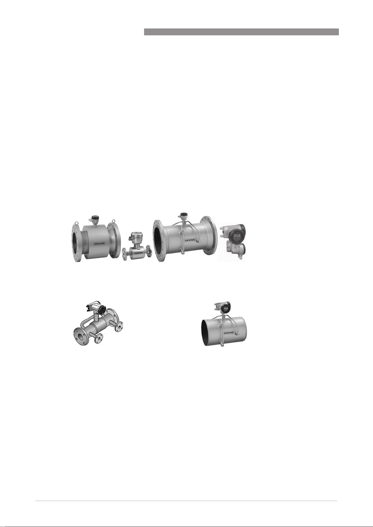
1.2 Variants
An OPTISONIC 3400
OPTISONIC 3400 flowmeter consists of an OPTISONIC 3000 flow sensor and an UFC 400
OPTISONIC 3400OPTISONIC 3400
signal converter. The standard version is available as a compact and remote version. Next to
standard, also variants for demanding applications can be supplied.
OPTISONIC 3000
OPTISONIC 3000
OPTISONIC 3000OPTISONIC 3000
Flow sensor variants for demanding applications
Flow sensor variants for demanding applications
Flow sensor variants for demanding applicationsFlow sensor variants for demanding applications
A full range of flow sensors to cover simple to difficult applications, such as:
• For extended process temperatures up to 250°C / 482°F (remote version)
• Cryogenic version: for extreme low process temperatures, as low as -200°C / [-328°F
(remote version, IP68)
• Flow sensor ≥ 14" and UFC 400 remote converter (aluminium or stainless steel housing)
• High viscous liquids: range from 100...1000 cSt
OPTISONIC 3400
Variants available on request
Including heating jacket
Including heating jacket
Including heating jacketIncluding heating jacket
• for steam or thermal oil tracing of the
flowmeter
• suitable for standard and variant for
extended process temperatures (remote)
Flangeless, weld-in connections
Flangeless, weld-in connections
Flangeless, weld-in connectionsFlangeless, weld-in connections
• greenfield
• flexibility in inner pipe diameters
6
www.krohne.com 2/2015 - 4002037603 TD OPTISONIC 3400 R03 en
OPTISONIC 3400
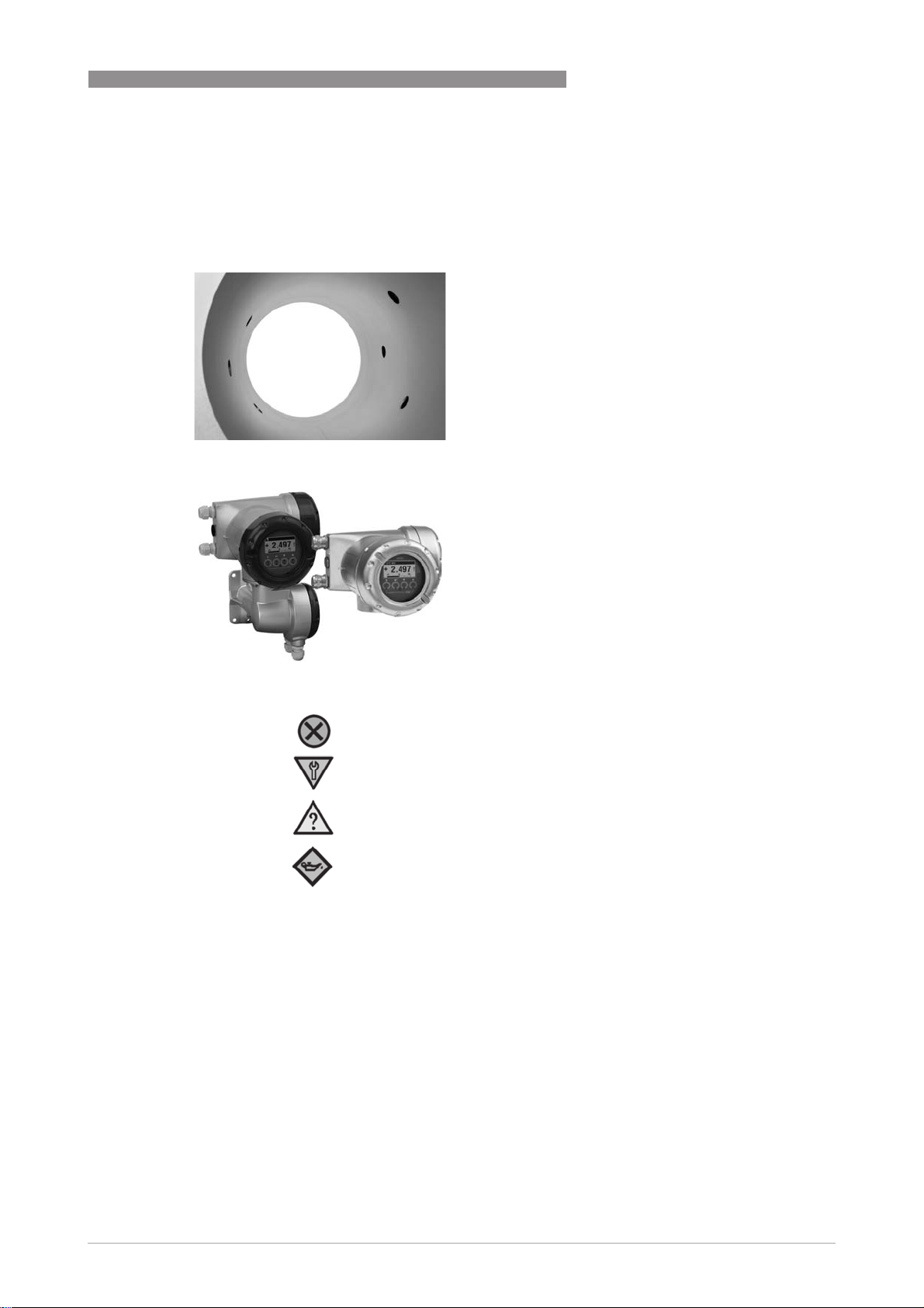
1.3 Features
PRODUCT FEATURES
Engineers favorite flow meter
Engineers favorite flow meter
Engineers favorite flow meterEngineers favorite flow meter
- All welded sensor construction
- Patented inert metal transducer technology
- No moving parts
- Full bore unobstructed sensor
- No need for auxiliary parts
UFC 400 signal converter - Compact and
UFC 400 signal converter - Compact and
UFC 400 signal converter - Compact and UFC 400 signal converter - Compact and
Remote/field
Remote/field
Remote/fieldRemote/field
- Display with 4 optical -or push buttons
- Many I/O configurations available
®
- Fieldbusses HART
- Optional Foundation Fieldbus, ITK6, Modbus
/RS485, Profibus PA/DP
(all included with NAMUR NE107 diagnostics)
- One universal software for all applications
7 (and HART registration)
1
Failure
Output signal invalid
Check function
Output signal (temporarily) invalid
Out of specification
Unreliability of output signal
Maintenance required
Output signal still valid
UFC 400 diagnostic capabilities:
UFC 400 diagnostic capabilities:
UFC 400 diagnostic capabilities: UFC 400 diagnostic capabilities:
NE107
NE107
NE107NE107
NE107 icons for status messages
and error handling
- visible on UFC 400 display
- via all communication protocols
- Status messages are grouped by
problem source
- User can change group or priority
www.krohne.com2/2015 - 4002037603 TD OPTISONIC 3400 R03 en
7
1
PRODUCT FEATURES
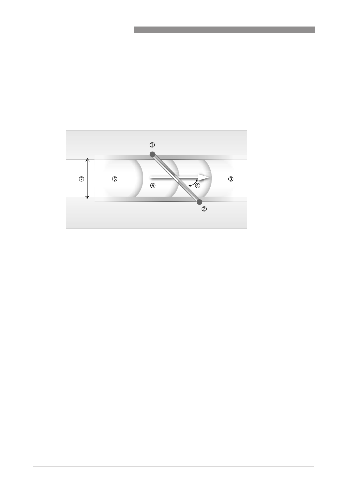
1.4 Measuring principle
• Like canoes crossing a river, acoustic signals are transmitted and received along a diagonal
measuring path.
• A sound wave going downstream with the flow travels faster than a sound wave going
upstream against the flow.
• The difference in transit time is directly proportional to the mean flow velocity of the medium.
OPTISONIC 3400
Figure 1-1: Measuring principle
1 Transducer A
2 Transducer B
3 Flow velocity
4 Angle of incidence
5 Velocity of sound of liquid
6 Path length
7 Inner diameter
8
www.krohne.com 2/2015 - 4002037603 TD OPTISONIC 3400 R03 en

OPTISONIC 3400
2.1 Technical data
•
The following data is provided for general applications. If you require data that is more
relevant to your specific application, please contact us or your local sales office.
•
Additional information (certificates, special tools, software,...) and complete product
documentation can be downloaded free of charge from the website (Download Center).
Measuring system
Measuring principle Ultrasonic transit time
Application range Flow measurement of (non) conductive fluids
Measured value
Measured value
Measured valueMeasured value
Primary measured value Transit time
Secondary measured values Volume flow, mass flow, flow speed, flow direction,
TECHNICAL DATA
velocity of sound, gain, signal to noise ratio, reliability of
flow measurement, totalised volume or mass
2
Design
Features 3 parallel acoustic paths fully welded.
Modular construction The measurement system consists of a measuring sensor
Compact version OPTISONIC 3400
Remote version OPTISONIC 3000 F with UFC 400 signal converter
Nominal diameter DN25...3000 / 1...120"
Measurement range 0.3...20 m/s / 0.98...65 ft/s
Signal converter
Signal converter
Signal converterSignal converter
Inputs / outputs
Totaliser 2 (optional 3) internal totalisers with a max. of 8 digits
Verification and self-diagnostics Integrated verification, diagnostic functions: measuring
Communication interfaces
and a signal converter.
Current (incl. HART®), pulse, frequency and/or status
output, limit switch and/or control input (depending on
the I/O version)
(e.g. for totalising volume and/or mass units)
device, process, measured values, device configuration,
etc.
Modbus RS485, HART® 7, Foundation Fieldbus ITK6,
Profibus PA/DP Profile 3.02
www.krohne.com2/2015 - 4002037603 TD OPTISONIC 3400 R03 en
9

2
TECHNICAL DATA
Display and user interface
Display and user interface
Display and user interfaceDisplay and user interface
Graphic display LC display, backlit white
Operating elements 4 optical and push buttons for operator control of the
Remote operation
Display functions
Display functions
Display functionsDisplay functions
Operating menu Programming of parameters at 2 measured value pages,
Language of display texts ( as language
package)
Measurement functions Units:
Diagnostic functions Standards:
OPTISONIC 3400
Size: 128x64 pixels.
Corresponds to 59x31 mm = 2.32"x1.22"
Display turnable in 90° steps.
signal converter without opening the housing.
Option: Infrared interface (GDC)
PACTwareTM including Device Type Manager (DTM)
HART® handheld communicator (Emerson), AMS
(Emerson), PDM (Siemens)
All DTM's and drivers will be available at the internet
homepage of the manufacturer.
1 status page, 1 graphic page (measured values and
descriptions adjustable as required)
Standard: English, French, German, Dutch
Russia: English, German, Russian
Units: Metric, British and US units selectable as desired
Units:Units:
from lists for volume/mass flow and counting, velocity,
temperature.
Measured values:
Measured values: volume flow, mass flow, flow speed,
Measured values:Measured values:
velocity of sound, gain, signal to noise ratio, flow
direction, diagnostics
Standards: VDI/NAMUR NE 107
Standards:Standards:
Status messages:
Status messages: Output of status messages via display,
Status messages:Status messages:
current and/or status output, HART
interface
Sensor diagnostics:
Sensor diagnostics: per acoustic path velocity of sound,
Sensor diagnostics:Sensor diagnostics:
flow speed, gain, signal to noise ratio
Process diagnostics:
Process diagnostics: empty pipe, signal integrity, cabling,
Process diagnostics:Process diagnostics:
flow conditions
Signal converter diagnostics:
Signal converter diagnostics: data bus monitoring, I/O
Signal converter diagnostics:Signal converter diagnostics:
connections, electronics temperature, parameter and
data integrity
®
or via other bus
10
Measuring accuracy
Reference conditions
Reference conditions
Reference conditions Reference conditions
Medium Water
Temperature 20°C / 68°F
Pressure 1 bar / 14.5 psi
Inlet section 10 DN
Maximum measuring error
Maximum measuring error
Maximum measuring errorMaximum measuring error
Standard: ±0.3% +2 mm/s of actual measured flow rate
Repeatability ±0.2%
www.krohne.com 2/2015 - 4002037603 TD OPTISONIC 3400 R03 en

OPTISONIC 3400
Operating conditions
Temperature
Temperature
TemperatureTemperature
Process temperature Compact version:
Ambient temperature Depending on the version and combination of outputs
Protect inside electronics against self-heating (increasing of the electronics temperature will lead to a
reduction of the corresponding service life by a factor 2 for each step of 10°C / 50°F increase).
Protect the signal converter from external heat sources such as direct sunlight, as higher temperatures
reduce the life cycle of all electronic components.
Storage temperature -50…+70°C / -58…+158°F
Pressure
Pressure
PressurePressure
Atmospheric
EN 1092-1 DN25…80: PN 40
ASME B16.5 1…24": 150 lb RF
JIS DN25...40: 20K
Properties of medium
Properties of medium
Properties of mediumProperties of medium
Physical condition Liquid, single phase (well mixed, rather clean)
Permissible gas content ≤ 2% (volume)
Permissible solid content ≤ 5% (volume)
Viscosity Standard:
TECHNICAL DATA
Compact version: -45...+140°C / -49...+284°F
Compact version:Compact version:
(for stainless steel housing at ambient temperature ≤
45°C / +113°F)
Remote version:
Remote version: -45...+180°C / -49...+356°F
Remote version:Remote version:
Extended temperature version:
Extended temperature version: -45...+250°C / -49...+482°F
Extended temperature version:Extended temperature version:
(only remote version)
Cryogenic version:
Cryogenic version: -200...+180°C / -328...+356°F (only
Cryogenic version:Cryogenic version:
remote version, IP68, complete stainless steel)
Carbon steel flanges;
minimal process temperatures acc. to EN1092: -10°C /
+14°F; ASME: -29°C / -20°F
-40…+65°C / -40…+149°F
Option (stainless steel converter housing): -40...+60°C /
-40...+140°F
Ambient temperatures below -25°C / -13°F may affect the
readability of the display.
DN100…150: PN 16
DN200…1000: PN 10
DN1200…3000: PN 6
Higher pressure ratings on request
1…24": 300 lb RF
1…24": 600 lb RF
1...24": 900 lb RF
Larger diameters on request.
DN50...300: 10K
Standard: Up to 100 cSt (for all diameters)
Standard:Standard:
Option:
Option: High viscosity variant up to 1000 cSt
Option:Option:
2
www.krohne.com2/2015 - 4002037603 TD OPTISONIC 3400 R03 en
11

2
TECHNICAL DATA
Installation conditions
Installation conditions
Installation conditionsInstallation conditions
Installation For detailed information refer to
Inlet run Minimal 5 DN (straight inlet)
Outlet run Minimal 3 DN (straight outlet)
Dimensions and weights For detailed information refer to
Materials
Materials
MaterialsMaterials
Measuring sensor
Measuring sensor
Measuring sensorMeasuring sensor
Flanges
(wetted)
Measuring Tube
(wetted)
Measuring sensor housing DN25...300 / 1"...12": Carbon steel
Transducer
Transducers (wetted) Stainless steel 1.4404 (AISI 316L)
Transducer holders
incl. caps
Tube transducer cabling Stainless steel 1.4404 (AISI 316L)
Connection box and connection box support
(remote version only)
Coating (measuring sensor) Standard: Polyurethane
NACE conformity On request; wetted materials conform NACE MR 175/103
Signal converter
Signal converter
Signal converterSignal converter
Housing Versions C and F: Die-cast aluminium
Coating Standard: Polyurethane
OPTISONIC 3400
Installation
If no details are known, minimal 10 DN recommended
If no details are known, minimal 5 DN recommended
on page 35.
Dimensions and weights
on page 21.
DN25...3000 / 1"...120": Carbon steel
Option: Stainless steel 1.4404 (AISI 316(L))
Other materials on request.
DN25...3000 / 1"...120": Carbon steel
Option: Stainless steel 1.4404 (AISI 316(L))
Other materials on request.
Option: Stainless steel 1.4404 (AISI 316(L))
For XXT, HV variant and DN25...3000 / 1"...120": Carbon
steel
For Cryogenic variant and DN25...3000 / 1"...120":
Stainless steel 1.4404 (AISI 316(L))
Other materials on request.
DN350...3000 / 14"...120"; Stainless steel 1.4404 (AISI
316L)
Standard: Die-cast aluminium; polyurethane coated
Option: Stainless steel 316 (1.4408)
Option: Offshore coating
Option: Stainless steel 316 (1.4408)
Option: Offshore coating
12
www.krohne.com 2/2015 - 4002037603 TD OPTISONIC 3400 R03 en

OPTISONIC 3400
Electrical connections
Electrical connections
Electrical connectionsElectrical connections
Description of used abbreviations; Q=xxx; I
= external voltage; U
General Electrical connection is carried out in conformity with the
Power supply Standard: 100…230 VAC (-15% / +10%), 50/60 Hz
Power consumption AC: 22 VA
Signal cable
(remote version only)
Cable entries Standard: M20 x 1.5 (8...12 mm)
= maximal internal voltage
int, max
TECHNICAL DATA
= maximum current; Uin = xxx; U
max
VDE 0100 directive "Regulations for electrical power
installations with line voltages up to 1000 V" or equivalent
national specifications.
Option: 24 VAC/DC (AC: -15% / +10%; DC: -25% / +30%)
DC: 12 W
MR06 (shielded cable with 6 coax cores): Ø 10.6 mm / 0.4"
5 m / 16 ft
Option: 10...30 m / 33...98 ft
Option: ½" NPT, PF ½
= internal voltage; U
int
ext
2
Inputs and outputs
General All outputs are electrically isolated from each other and
Description of used abbreviations U
from all other circuits.
All operating data and output values can be adjusted.
= external voltage; RL = load + resistance;
ext
= terminal voltage; I
U
0
Safety limit values (Ex i):
= max. input voltage; Ii = max. input current; Pi = max.
U
i
input power rating;
Ci = max. input capacity; Li = max. input inductivity
= nominal current
nom
www.krohne.com2/2015 - 4002037603 TD OPTISONIC 3400 R03 en
13

2
TECHNICAL DATA
Current output
Current output
Current outputCurrent output
Output data Measurement of volume flow, mass flow, flow speed,
Temperature coefficient Typically ±30 ppm/K
Settings
Operating data Basic I/Os
Active U
OPTISONIC 3400
velocity of sound, gain, SNR, diagnostics (flow speed,
VoS, SNR, gain), NAMUR NE107, HART
Without HART
Without HART
Without HARTWithout HART
®
Q = 0%: 0…20 mA; Q = 100%: 10…20 mA
Error identification: 3…22 mA
With HART
With HART
With HARTWith HART
®
Q = 0%: 4…20 mA; Q = 100%: 10…20 mA
Error identification: 3…22 mA
Q = 100%: 10…20 mA
Error identification: 3…22 mA
Basic I/Os Modular I/Os
Basic I/OsBasic I/Os
= 24 VDC
int, nom
Modular I/Os Ex i
Modular I/OsModular I/Os
®
communication.
Ex i
Ex iEx i
U
int, nom
= 20 VDC
Passive U
I ≤ 22 mA
≤ 1kΩ
R
L
≤ 32 VDC
ext
I ≤ 22 mA
≥ 1.8 V
U
0
R
= (U
L, max
- U0 / I
ext
max
I ≤ 22 mA
≤ 450 Ω
R
L
U0=21V
I0=90mA
=0.5W
P
0
C0= 90 nF / L0 =
2mH
=110nF/
C
0
L0=0.5mH
U
≤ 32 VDC
ext
I ≤ 22 mA
≥ 4V
U
0
R
= (U
L, max
U
0
/ I
max
ext
-
Ui=30V
Ii= 100 mA
=1W
P
i
C
= 10 nF
i
~0mH
L
i
14
www.krohne.com 2/2015 - 4002037603 TD OPTISONIC 3400 R03 en

OPTISONIC 3400
HART
HART
HARTHART
Description
Load
Multidrop Yes, current output = 10% e.g. 4 mA
Device drivers DD for FC 375/475, AMS, PDM, DTM for FDT
Pulse or frequency output
Pulse or frequency output
Pulse or frequency outputPulse or frequency output
Output data Volume flow, mass flow
Function Adjustable as pulse of frequency output
Pulse rate/frequency 0.01...10000 pulses/s or Hz
Settings For Q = 100%: 0.01... 10000 pulses per second or pulses
Operating data Basic I/Os Modular I/Os Ex i
Active - U
TECHNICAL DATA
®
2
HART® protocol via active and passive current output
HART® version: V7
Universal HART® parameter: completely integrated
≥ 250 Ω t HART® test point:
Note maximum load for current output!
Multidrop addresses adjustable in operation menu 0...63
per unit volume.
Pulse width: adjustable as automatic, symmetric or fixed
(0.05...2000 ms)
= 24 VDC -
nom
f
in operating
max
menu set to:
ffff
≤ 100 Hz:
100 Hz:
100 Hz: 100 Hz:
max
max
max max
I ≤ 20 mA
= 47 kΩ
R
L, max
open:
I ≤ 0.05 mA
closed:
=24V at
U
0,nom
I=20mA
F
in operating
max
menu set to:
≤ 10
100 Hz < f
100 Hz < f
100 Hz < f100 Hz < f
kHz:
kHz:
kHz:kHz:
max
max
maxmax
10
10 10
I ≤ 20 mA
RL ≤ 10 kΩ for f ≤
1 kHz
≤ 1 kΩ for f ≤
R
L
10 kHz
open:
I ≤ 0.05 mA
closed:
U
= 22.5 V at
0,nom
I=1mA
= 21.5 V at
U
0,nom
I=10mA
U
0,nom
=19V at
I=20mA
www.krohne.com2/2015 - 4002037603 TD OPTISONIC 3400 R03 en
15

2
TECHNICAL DATA
OPTISONIC 3400
Passive U
≤ 32 VDC -
ext
f
in operating menu set to:
max
≤ 100 Hz:
100 Hz:
ffff
100 Hz: 100 Hz:
max
max
maxmax
I ≤ 100 mA
R
= 47 kΩ
L, max
= (U
R
L, max
- U0) / I
ext
max
open:
I ≤ 0.05 mA at U
=32VDC
ext
closed:
=0.2V at I≤ 10 mA
U
0, max
U
= 2 V at I ≤ 100 mA
0, max
f
in operating menu set to:
max
100 Hz < f
100 Hz < f
100 Hz < f100 Hz < f
≤ 10 kHz:
max
max
maxmax
10 kHz:
10 kHz: 10 kHz:
I ≤ 20 mA
RL ≤ 10 kΩ for f ≤ 1 kHz
≤ 1 kΩ for f ≤ 10 kHz
R
L
R
= (U
L, max
- U0) / I
ext
max
open:
I ≤ 0.05 mA at U
= 32 VDC
ext
closed:
U
=1.5V at I≤ 1mA
0, max
=2.5V at I≤ 10 mA
U
0, max
U
=5.0V at I≤ 20 mA
0, max
NAMUR - Passive to
EN 60947-5-6
Passive to
EN 60947-5-6
open:
I
= 0.6 mA
nom
closed:
=3.8mA
I
nom
open:
I
=0.43mA
nom
closed:
= 4.5 mA
I
nom
Ui=30V
= 100 mA
I
i
=1W
P
i
Ci=10nF
=0mH
L
i
16
www.krohne.com 2/2015 - 4002037603 TD OPTISONIC 3400 R03 en