

Page 1
Handbook
Handbook
OPTIMASS 7000
OPTIMASS 7000
OPTIMASS 7000OPTIMASS 7000
HandbookHandbook
Sensor for mass flow
The documentation is only complete when used in combination with the relevant
documentation for the signal converter.
© KROHNE 04/2013 - 4001016302 - MA OPTIMASS 7000 R02 en
Page 2

: IMPRINT :::::::::::::::::::::::::::::::::::::::
All rights reserved. It is prohibited to reproduce this documentation, or any part thereof, without
the prior written authorisation of KROHNE Messtechnik GmbH.
Subject to change without notice.
Copyright 2013 by
KROHNE Messtechnik GmbH - Ludwig-Krohne-Str. 5 - 47058 Duisburg (Germany)
2
www.krohne.com 04/2013 - 4001016302 - MA OPTIMASS 7000 R02 en
Page 3

OPTIMASS 7000
CONTENTS
1 Safety instructions 5
1.1 Software history ............................................................................................................... 5
1.2 Intended use ..................................................................................................................... 5
1.3 CE certification ................................................................................................................. 5
1.4 Associated documents ..................................................................................................... 6
1.5 Pressure Equipment Directive (PED)............................................................................... 7
1.6 Safety instructions from the manufacturer ..................................................................... 7
1.6.1 Copyright and data protection ................................................................................................ 7
1.6.2 Disclaimer ............................................................................................................................... 8
1.6.3 Product liability and warranty ................................................................................................ 9
1.6.4 Information concerning the documentation........................................................................... 9
1.6.5 Warnings and symbols used................................................................................................. 10
1.7 Safety instructions for the operator............................................................................... 10
2 Device description 11
2.1 Scope of delivery............................................................................................................. 11
2.1.1 Meters with hygienic connections ........................................................................................ 12
2.2 Nameplates .................................................................................................................... 12
2.3 CSA Dual Seal................................................................................................................. 12
2.4 Temperature differential and thermal shock ................................................................ 13
3 Installation 15
3.1 General notes on installation ......................................................................................... 15
3.2 Storage ........................................................................................................................... 15
3.3 Handling.......................................................................................................................... 16
3.4 Installation conditions ....................................................................................................18
3.4.1 Supporting the meter............................................................................................................ 18
3.4.2 Mounting the meter .............................................................................................................. 19
3.4.3 Cross talk .............................................................................................................................. 20
3.4.4 Flange connections............................................................................................................... 20
3.4.5 Maximum pipework forces (end loadings) ........................................................................... 21
3.4.6 Pipework reducers................................................................................................................ 21
3.4.7 Flexible connections ............................................................................................................. 22
3.4.8 Hygienic installations............................................................................................................ 22
3.4.9 Heating and insulation .......................................................................................................... 23
3.4.10 Purge ports ......................................................................................................................... 25
3.4.11 Zero calibration................................................................................................................... 25
3.4.12 Sunshades........................................................................................................................... 27
4 Electrical connections 28
4.1 Safety instructions.......................................................................................................... 28
4.2 Electrical and I/O connections ....................................................................................... 28
www.krohne.com04/2013 - 4001016302 - MA OPTIMASS 7000 R02 en
3
Page 4

CONTENTS
OPTIMASS 7000
5 Service 29
5.1 Spare parts availability...................................................................................................29
5.2 Availability of services .................................................................................................... 29
5.3 Returning the device to the manufacturer..................................................................... 29
5.3.1 General information.............................................................................................................. 29
5.3.2 Form (for copying) to accompany a returned device............................................................ 30
5.4 Disposal .......................................................................................................................... 30
6 Technical data 31
6.1 Measuring principle (single tube) .................................................................................. 31
6.2 Technical data................................................................................................................. 33
6.3 Measuring accuracy ....................................................................................................... 39
6.4 Guidelines for maximum operating pressure................................................................ 40
6.5 Dimensions and weights ................................................................................................ 44
6.5.1 Flanged versions................................................................................................................... 44
6.5.2 Hygienic versions .................................................................................................................. 47
6.5.3 Heating jacket version .......................................................................................................... 53
6.5.4 Purge port option .................................................................................................................. 54
7 Notes 55
4
www.krohne.com 04/2013 - 4001016302 - MA OPTIMASS 7000 R02 en
Page 5
OPTIMASS 7000
1.1 Software history
Release date Software version Documentation
Aug 2008 V2.2.xx MA MFC 300 R02
1.2 Intended use
This mass flowmeter is designed for the direct measurement of mass flow rate, product density
and product temperature. Indirectly, it also enables the measurement of parameters like total
mass, concentration of dissolved substances and the volume flow. For use in hazardous areas,
special codes and regulations are also applicable and these are specified in a separate
documentation.
1.3 CE certification
CE marking
SAFETY INSTRUCTIONS 1
MA MFC 010 R03
This device conforms with the following EC directives:
• EMC Directive 2004/108/EC
• ATEX Directive 94/9/EC
• Low Voltage Directive 2006/95/EC
• Pressure Equipment Directive 97/23/EC
The manufacturer declares conformity and the device carries the CE mark.
www.krohne.com04/2013 - 4001016302 - MA OPTIMASS 7000 R02 en
5
Page 6

1 SAFETY INSTRUCTIONS
1.4 Associated documents
This handbook should be read in conjunction with relevant documents in relation to:
• hazardous areas
• communications
• concentration
• corrosion
OPTIMASS 7000
6
www.krohne.com 04/2013 - 4001016302 - MA OPTIMASS 7000 R02 en
Page 7
OPTIMASS 7000
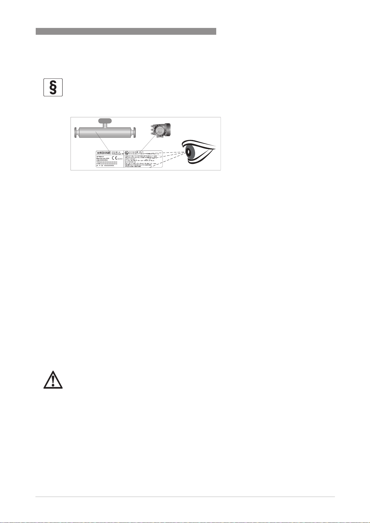
1.5 Pressure Equipment Directive (PED)
LEGAL NOTICE!
The Pressure Equipment Directive places legal requirements on both the manufacturer and the
end user. Please read this section carefully!
Visual check
XXXXX
To ensure the PED integrity of the meter, you MUST check that the serial numbers on the
converter nameplate and the sensor nameplate are the same.
To comply with the requirements of the Pressure Equipment Directive (PED) the manufacturer
provides all the relevant technical data in the technical data section of this handbook. In addition
to which, the following should also be noted:
SAFETY INSTRUCTIONS 1
• Secondary pressure containment is NOT supplied as standard.
• The non PED / CRN approved outer cyclinder has a typical burst pressure greater than
100 barg / 1450 psig at 20°C/68°F.
• The wiring feedthrough is made of Epoxy, PPS or PEEK with two O-rings made from FPM /
FKM & Hydrogenated Nitrile.
• If the measuring tube/s fails, the O-ring and feedthrough will be in contact with the process
product.
• You MUST make sure that the O-ring and feedthrough material is suitable for the application.
• Alternative O-ring materials are available on request.
Secondary pressure containment
Where the meter is being used to measure high pressure gases and / or gases kept as liquids by
high pressure and / or where there is a risk of tube failure because of the use of corrosive or
erosive fluids, frequent pressure and / or thermal cycling, seismic or other shock loading, a
secondary containment option MUST be purchased
DANGER!
If it is suspected that the primary measuring tube has failed, de-pressurise the meter and
remove it from service as soon as it is safe to do so. Where the meter has a Tantalum primary
measuring tube, extra care MUST be taken because the process fluid might be highly toxic and /
or corrosive to the outer cylinder, wiring feedthrough and O-rings.
1.6 Safety instructions from the manufacturer
1.6.1 Copyright and data protection
The contents of this document have been created with great care. Nevertheless, we provide no
guarantee that the contents are correct, complete or up-to-date.
www.krohne.com04/2013 - 4001016302 - MA OPTIMASS 7000 R02 en
7
Page 8

1 SAFETY INSTRUCTIONS
The contents and works in this document are subject to copyright. Contributions from third
parties are identified as such. Reproduction, processing, dissemination and any type of use
beyond what is permitted under copyright requires written authorisation from the respective
author and/or the manufacturer.
The manufacturer tries always to observe the copyrights of others, and to draw on works created
in-house or works in the public domain.
The collection of personal data (such as names, street addresses or e-mail addresses) in the
manufacturer's documents is always on a voluntary basis whenever possible. Whenever
feasible, it is always possible to make use of the offerings and services without providing any
personal data.
We draw your attention to the fact that data transmission over the Internet (e.g. when
communicating by e-mail) may involve gaps in security. It is not possible to protect such data
completely against access by third parties.
We hereby expressly prohibit the use of the contact data published as part of our duty to publish
an imprint for the purpose of sending us any advertising or informational materials that we have
not expressly requested.
OPTIMASS 7000
1.6.2 Disclaimer
The manufacturer will not be liable for any damage of any kind by using its product, including,
but not limited to direct, indirect or incidental and consequential damages.
This disclaimer does not apply in case the manufacturer has acted on purpose or with gross
negligence. In the event any applicable law does not allow such limitations on implied warranties
or the exclusion of limitation of certain damages, you may, if such law applies to you, not be
subject to some or all of the above disclaimer, exclusions or limitations.
Any product purchased from the manufacturer is warranted in accordance with the relevant
product documentation and our Terms and Conditions of Sale.
The manufacturer reserves the right to alter the content of its documents, including this
disclaimer in any way, at any time, for any reason, without prior notification, and will not be liable
in any way for possible consequences of such changes.
8
www.krohne.com 04/2013 - 4001016302 - MA OPTIMASS 7000 R02 en
Page 9

OPTIMASS 7000
1.6.3 Product liability and warranty
The operator shall bear responsibility for the suitability of the device for the specific purpose.
The manufacturer accepts no liability for the consequences of misuse by the operator. Improper
installation and operation of the devices (systems) will cause the warranty to be void. The
respective "Standard Terms and Conditions" which form the basis for the sales contract shall
also apply.
1.6.4 Information concerning the documentation
To prevent any injury to the user or damage to the device it is essential that you read the
information in this document and observe applicable national standards, safety requirements
and accident prevention regulations.
If this document is not in your native language and if you have any problems understanding the
text, we advise you to contact your local office for assistance. The manufacturer can not accept
responsibility for any damage or injury caused by misunderstanding of the information in this
document.
This document is provided to help you establish operating conditions, which will permit safe and
efficient use of this device. Special considerations and precautions are also described in the
document, which appear in the form of underneath icons.
SAFETY INSTRUCTIONS 1
www.krohne.com04/2013 - 4001016302 - MA OPTIMASS 7000 R02 en
9
Page 10
1 SAFETY INSTRUCTIONS
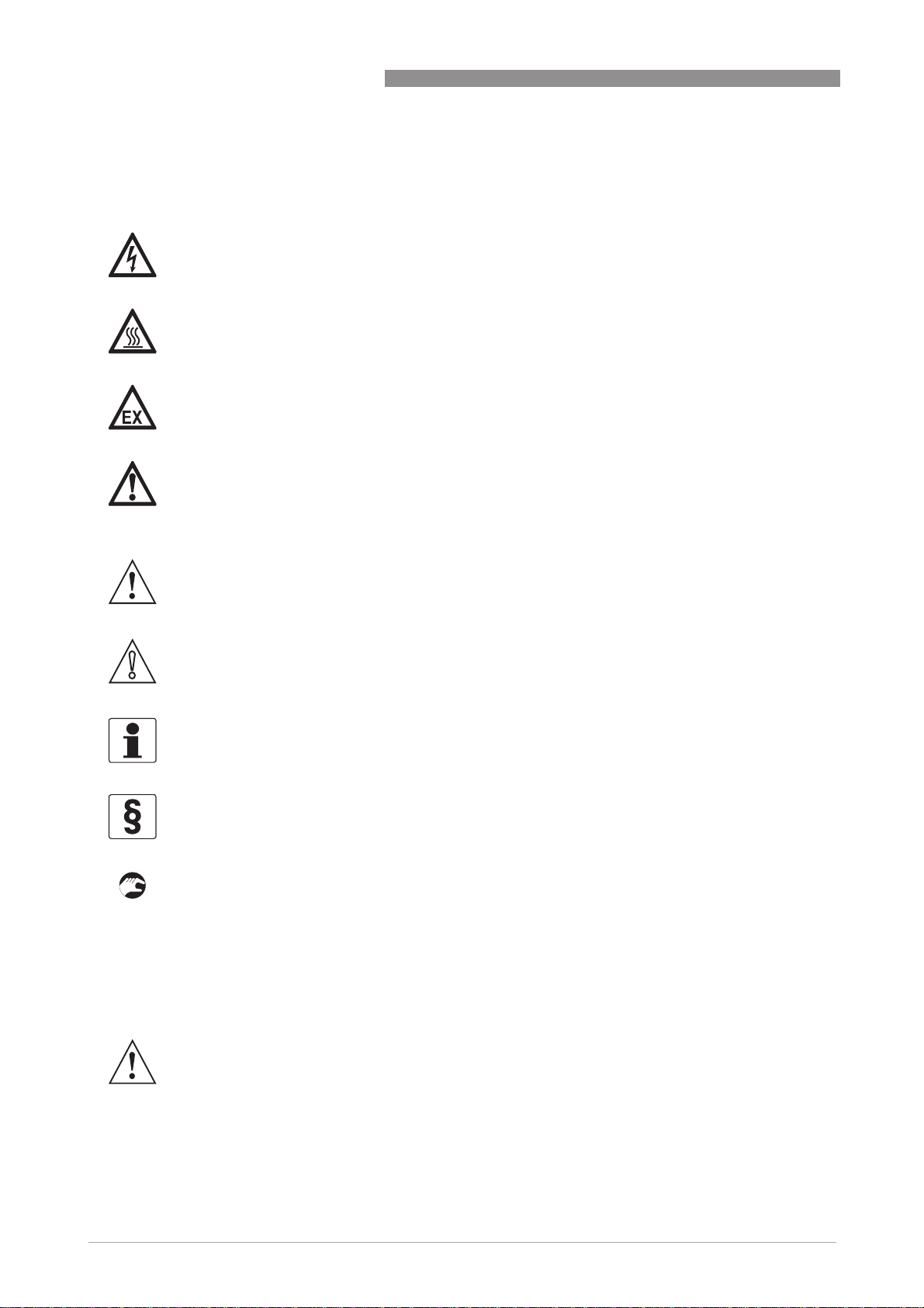
1.6.5 Warnings and symbols used
Safety warnings are indicated by the following symbols.
DANGER!
This information refers to the immediate danger when working with electricity.
DANGER!
This warning refers to the immediate danger of burns caused by heat or hot surfaces.
DANGER!
This warning refers to the immediate danger when using this device in a hazardous atmosphere.
DANGER!
These warnings must be observed without fail. Even partial disregard of this warning can lead to
serious health problems and even death. There is also the risk of seriously damaging the device
or parts of the operator's plant.
OPTIMASS 7000
WARNING!
Disregarding this safety warning, even if only in part, poses the risk of serious health problems.
There is also the risk of damaging the device or parts of the operator's plant.
CAUTION!
Disregarding these instructions can result in damage to the device or to parts of the operator's
plant.
INFORMATION!
These instructions contain important information for the handling of the device.
LEGAL NOTICE!
This note contains information on statutory directives and standards.
• HANDLING
HANDLING
HANDLINGHANDLING
This symbol designates all instructions for actions to be carried out by the operator in the
specified sequence.
i RESULT
RESULT
RESULTRESULT
This symbol refers to all important consequences of the previous actions.
1.7 Safety instructions for the operator
10
WARNING!
In general, devices from the manufacturer may only be installed, commissioned, operated and
maintained by properly trained and authorized personnel.
This document is provided to help you establish operating conditions, which will permit safe and
efficient use of this device.
www.krohne.com 04/2013 - 4001016302 - MA OPTIMASS 7000 R02 en
Page 11
OPTIMASS 7000
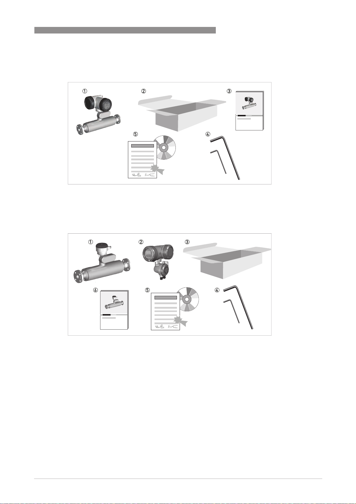
2.1 Scope of delivery
Compact version
1 Mass flowmeter.
2 Carton.
3 Documentation.
4 2.5 mm and 5 mm hex head tools.
5 CD-ROM and calibration certificate.
DEVICE DESCRIPTION 2
Remote version
1 Mass flowmeter.
2 Converter. This will be either: field (as shown), wall or rack.
3 Carton.
4 2.5 mm and 5 mm hex head tools.
5 CD-ROM and calibration certificate.
6 Documentation.
If any items are missing, please contact the manufacturer.
If your meter has flange connections, the flange specification is stamped on the outer edge of the
flange. Check that the specification on the flange is the same as your order.
www.krohne.com04/2013 - 4001016302 - MA OPTIMASS 7000 R02 en
11
Page 12
2 DEVICE DESCRIPTION
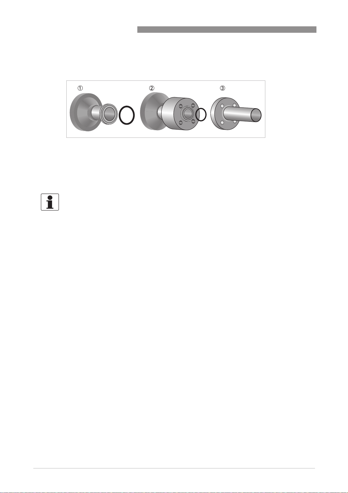
2.1.1 Meters with hygienic connections
1 Fully welded - the O-rings between the meter and the process pipework are not supplied as standard but can be or-
dered.
2 DIN 11864-2 Form A - the O-rings between the Form A and Form B parts of the connection are not supplied as standard
but can be ordered.
3 The 11864-2 Form B is not supplied as part of this connection but it can be ordered.
2.2 Nameplates
INFORMATION!
Look at the device nameplate to ensure that the device is delivered according to your order.
Check for the correct supply voltage printed on the nameplate.
OPTIMASS 7000
2.3 CSA Dual Seal
To comply with the requirements of ANSI/ISA -12.27.01-2003 “Requirements for process Sealing
Between electrical systems and Flammable or Combustible process Fluids” a secondary seal is
incorporated into all OPTIMASS / GAS products. If the primary seal fails, the secondary seal will
prevent escaping fluid reaching the electronic compartment.
Pressures and / or temperatures are limited by tube, temperature, connection and Ex limits.
Check the meter nameplates and relevant documentation for full details. On all meters
operating on gas measurement, the casing of the meter is fitted with a burst disc. If the primary
seal (tube) fails leakage will occur from the burst disc. Install the meter so that the burst disc is
pointing away from personnel.
Liquids
Liquids (Example model code: OPTIMASS 7000C S25)
LiquidsLiquids
Pressure and temperature data:
Pressure and temperature data:
Pressure and temperature data:Pressure and temperature data:
OPTIMASS 7000 / 7300 / 7010 -40°C...+150°C and 100...10000 kPa
Pressures and/or temperatures may be further limited by tube, temperature, connection and Ex
limits. Consult the meter nameplate and relevant documentation for full details
If the primary seal fails, the casing of the meter will fill with liquid and the meter will stop
working. The meter will notify the operator by going into <Startup> mode and a diagnostic error
will be shown on the converter or PLC display. This is an indication that the primary seal (tube)
has failed and the status of the meter should be checked.
12
Meter status:
Meter status:
Meter status:Meter status:
The meter will also go into <Startup> mode if the primary seal (tube) fails, or if they are not
completely filled with fluid. For example, if the meter is drained or re/filled.
www.krohne.com 04/2013 - 4001016302 - MA OPTIMASS 7000 R02 en
Page 13

OPTIMASS 7000
To check the status of the meter, drain and re/fill with fluid and note the converter or PLC
display. See the relevant section of the converter handbook for a list of status messages and
diagnostics information.
If the meter remains in <Startup> mode you MUST assume that the primary seal (tube) has failed
and the appropriate action MUST be taken.
Gases
Gases (Example model code: OPTIMASS 7000C S25)
GasesGases
Pressure / temperature data:
Pressure / temperature data:
Pressure / temperature data:Pressure / temperature data:
OPTIMASS 7000 / 7300 / 7010 -40°C...+150°C and 500...10000 kPa
Pressures and/or temperatures may be further limited by tube, temperature, connection and Ex
limits. Consult the meter nameplate and relevant documentation for full details.
On all meters operating on gas measurement the casing of the meter is fitted with a burst disc. If
the primary seal (tube/s) fails leakage will occur from the burst disc. Install the meter so that the
burst disc is pointing away from personnel.
DEVICE DESCRIPTION 2
Regular maintenance of the burst disc:
Regular maintenance of the burst disc:
Regular maintenance of the burst disc:Regular maintenance of the burst disc:
Carry out regular maintenance checks on burst discs for leakage and/or blockages. On all
OPTIMASS meters, the primary seal is considered to be the measuring tube of the meter. The
materials of construction of the measuring tube/s are described within the relevant sections of
this handbook and the customer’s product and any other fluid flowing through the tube must be
compatible with the material of construction. If failure of the primary seal is suspected then the
process line should be de-pressurised and the meter removed as soon as it is safe to do so.
Please contact customer service for servicing or replacement of the meter.
2.4 Temperature differential and thermal shock
Temperature differential
Temperature differential
Temperature differentialTemperature differential
The maximum difference between ambient temperature and process (operating) temperature
varies according to the measuring tube material.
Meter
Meter Maximum temperature differential
MeterMeter
Titanium +130°C / +266°F
Stainless Steel +80°C / +176°F
Hastelloy +80°C / +176°F
Tantalum +80°C / +176°F
Maximum temperature differential
Maximum temperature differentialMaximum temperature differential
Extended range
Extended range
Extended rangeExtended range
Stainless Steel meters sizes 25, 40, 50 and 80 (fitted with hygienic connections) may be exposed
to a temperature difference of 110°C / 230°F for a maximum of 2 hours.
www.krohne.com04/2013 - 4001016302 - MA OPTIMASS 7000 R02 en
13
Page 14
2 DEVICE DESCRIPTION
Thermal shock
Thermal shock
Thermal shockThermal shock
Thermal shock occurs when there is a sudden and extreme change (shift) in process
temperature. To avoid thermal shock, refer to the following table for the maximum temperature
shift.
Meter
Meter Maximum temperature shift
MeterMeter
Titanium +130°C / +266°F
Stainless Steel +80°C / +176°F
Hastelloy® +80°C / +176°F
Tantalum +80°C / +176°F
CAUTION!
Operation outside these limits may result in shifts in density and mass flow calibration. Repeated
shocking may also lead to premature failure of the meter! However, higher thermal shocks are
possible at lower working pressures. For more information, please contact your nearest
representative.
Maximum temperature shift
Maximum temperature shiftMaximum temperature shift
OPTIMASS 7000
14
www.krohne.com 04/2013 - 4001016302 - MA OPTIMASS 7000 R02 en
Page 15

OPTIMASS 7000
3.1 General notes on installation
INFORMATION!
Inspect the cartons carefully for damages or signs of rough handling. Report damage to the
carrier and to the local office of the manufacturer.
INFORMATION!
Do a check of the packing list to make sure that you have all the elements given in the order.
INFORMATION!
Look at the device nameplate to ensure that the device is delivered according to your order.
Check for the correct supply voltage printed on the nameplate.
3.2 Storage
• Store the device in a dry and dust-free location.
• Avoid direct exposure to the sun.
• Store the device in its original packing.
• Do not allow the ambient temperature to fall below -50°C / -58°F or rise above +85°C /
+185°F.
INSTALLATION 3
www.krohne.com04/2013 - 4001016302 - MA OPTIMASS 7000 R02 en
15
Page 16
3 INSTALLATION
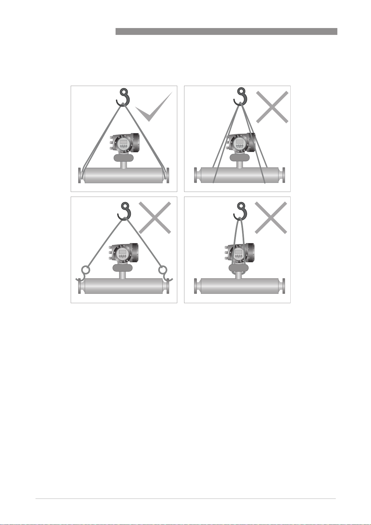
3.3 Handling
Using a sling to lift and carry the meter
1
OPTIMASS 7000
2
3
1 Use a well maintained sling to lift the meter by the spigots.
2 DO NOT lift the meter with the sling part way along the outer cylinder.
3 DO NOT lift the meter using the flange bolt holes.
4 DO NOT lift the meter by the converter housing or the electronics stem.
4
16
www.krohne.com 04/2013 - 4001016302 - MA OPTIMASS 7000 R02 en
Page 17
OPTIMASS 7000
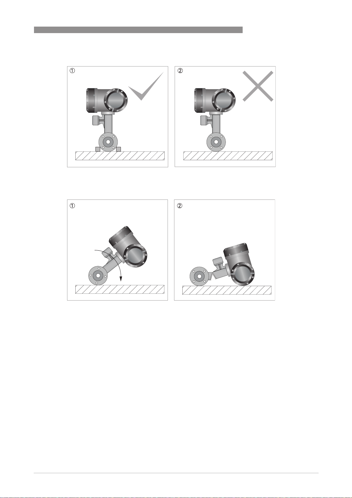
Standing the meter before installation
1 When standing the meter prior to installation, use blocks or similar to keep the meter upright.
2 NEVER stand the meter upright without blocks (or similar) .
INSTALLATION 3
1 If the meter is not blocked it can roll over
2 This can cause severe damage to the meter, or injury to personnel
www.krohne.com04/2013 - 4001016302 - MA OPTIMASS 7000 R02 en
17
Page 18

3 INSTALLATION
3.4 Installation conditions
3.4.1 Supporting the meter
Support for meters with flange connections
1 The meter can be supported directly by its body
2 The meter can also be supported by the process pipework
OPTIMASS 7000
Support for meters with hygienic connections
1 Always support the meter body.
2 DO NOT use the process pipework to support the weight of the meter. The thin wall of the pipework usually used in the
hygienic industry, is not strong enough to carry the weight of the meter.
CAUTION!
If there is excessive vibration in the process pipework, you must isolate the meter from its
mounting. It is recommended that you place an insert made from rubber (or similar material)
between the meter body, or pipework, and the mounting clamp or fixing point. For more
information, contact the manufacturer.
18
www.krohne.com 04/2013 - 4001016302 - MA OPTIMASS 7000 R02 en
Page 19

OPTIMASS 7000
3.4.2 Mounting the meter
Mounting positions
INSTALLATION 3
1 The meter can be mounted at an angle but it is recommended that the flow is uphill.
2 Avoid mounting the meter with the flow running downhill because it can cause siphoning. If the meter has to be mount-
ed with the flow running downhill, install an orifice plate or control valve downstream of the meter to maintain backpressure.
3 Horizontal mounting with flow running left to right.
4 Avoid mounting meter with long vertical runs after the meter as it can cause cavitation. Where the installation includes
a vertical run after the meter, install an orifice plate or control valve downstream to maintain backpressure.
5 The meter can be mounted vertically but it is recommended that the flow is uphill.
6 Avoid mounting the meter vertically with the flow running downhill. This can cause siphoning. If the meter has to be
installed this way, install an orifice plate or control valve downstream to maintain backpressure.
www.krohne.com04/2013 - 4001016302 - MA OPTIMASS 7000 R02 en
19
Page 20

3 INSTALLATION
3.4.3 Cross talk
Where more than one meter is being installed, a very high level of immunity to cross talk means
that the meters can be mounted within close proximity to each other. The meters can be
mounted either in series or parallel, as shown.
Meters in series
INFORMATION!
Where the meters are installed in series, it is strongly recommended that the process pipe
diameter remains constant. For more information, please contact the manufacturer.
OPTIMASS 7000
Meters in parallel
3.4.4 Flange connections
20
Tighten the flange bolts evenly and in turn.
www.krohne.com 04/2013 - 4001016302 - MA OPTIMASS 7000 R02 en
Page 21

OPTIMASS 7000
Use a regular pattern to tighten the bolts evenly
3.4.5 Maximum pipework forces (end loadings)
INSTALLATION 3
Mass flowmeters have a maximum level of force (negative or positive) that can be applied to the
ends of the meter. Refer to the table below for permitted forces.
Please refer to the table in the technical data section of this Handbook for the maximum end
loadings.
3.4.6 Pipework reducers
Always avoid extreme step changes in pipe size. Use pipework reducers, where there is a large
difference between pipework size and meter flanges.
www.krohne.com04/2013 - 4001016302 - MA OPTIMASS 7000 R02 en
21
Page 22

3 INSTALLATION
3.4.7 Flexible connections
Flexible connections can be used but because of the high flow rates associated with large
diameter meters, it is recommended that flexible connections are not used on meters larger
than size 80.
3.4.8 Hygienic installations
OPTIMASS 7000
22
1 Install the meter at an angle to allow self-draining.
2 DO NOT install the meter horizontally.
Where the meter has been approved by the sanitary requirements of the European Hygienic
Engineering and Design Group, you MUST give consideration to:
• Installation - install the meter at an angle to allow self-draining (see illustration).
• Cleaning fluids - cleaning fluids should flow uphill with a velocity rate greater than
1.5 m/s / 5ft/s. If the process flow is downhill, install a flow restrictor downstream of the
meter. This will make sure that the meter is completely filled with the cleaning fluid.
• Process connections and seals MUST be in accordance with EHEDG documentation.
The manufacturer also recommends that you refer to EHEDG (www.ehedg.org) document
number 8 "HYGIENIC EQUIPMENT DESIGN CRITERIA".
www.krohne.com 04/2013 - 4001016302 - MA OPTIMASS 7000 R02 en
Page 23

OPTIMASS 7000
3.4.9 Heating and insulation
Heating
Heating
HeatingHeating
The meter can be heated by electrical tape (or similar) as shown. ONLY heat the meter in the
area marked A.
Insulation
Insulation
InsulationInsulation
The meter can also be insulated to a maximum depth as shown (B). Do not insulate above this
depth as this will cause the electronics to overheat.
Electrical heating and insulation
INSTALLATION 3
1 Area that can be heated (A). Refer to the table for the maximum sizes.
2 Maximum depth of insulation (B). DO NOT insulate above this depth.
Heated area
Dimension of A [mm] 10 15 25 40 50 80
Titanium 50 65 120 150 200 410
Stainless Steel / Hastelloy® / Tantalum - 65 75 150 125 225
Dimension of A [inches] 10 15 25 40 50 80
Titanium 1.97 2.56 4.7 5.9 7.9 16.1
Stainless Steel / Hastelloy® / Tantalum - 2.56 2.9 5.9 4.9 8.8
www.krohne.com04/2013 - 4001016302 - MA OPTIMASS 7000 R02 en
23
Page 24

3 INSTALLATION
Factory fitted heating jacket
Factory fitted heating jacket
Factory fitted heating jacketFactory fitted heating jacket
If the meter has been ordered with a heating jacket, it will be supplied with NPT, Ermeto or
flange connections.
Connecting / using the heating jacket
• Use reinforced flexible hoses to connect the heating jacket to the heat source.
• The heating jacket material is 316L but the heating medium is also in contact with the outer
cylinder, which might be a lower grade Stainless Steel.
• Suitable heating mediums are steam or hot oil. Avoid the use of heating mediums that can
cause crevice corrosion in Stainless Steel.
• Where liquid is being used, set up the pipe configuration so that air can be vented from the
system.
• Where steam is being used, set up the pipe configuration so that condensation can be drained
off.
• Heat the jacket to working temperature before flowing the process fluid through the meter.
OPTIMASS 7000
CAUTION!
°
The maximum heating jacket pressure and temperature is 10 barg at 150
°
for Titanium measuring tubes and 10 barg at 100
C / 145 psig at 212°C for Stainless Steel,
C / 145 psig at 302°F
Hasteloy and Tantalum measuring tubes.
Heating times
Temperature [°C / °F] 1 Time [minutes] for Titanium measuring tube
10 15 25 40 50 80
40 / 104 30 90
60 / 140 80 160
80 / 176 120 330
100 / 212 190 495
120 / 248 270 735
140 / 284 480 1320
1 Measured at the centre of the measuring tube.
24
www.krohne.com 04/2013 - 4001016302 - MA OPTIMASS 7000 R02 en
Page 25

OPTIMASS 7000
Temperature [°C / °F] 1 Time [minutes] for Stainless Steel, Hastelloy® and Tantalum
40 / 104 105 90
60 / 140 190 240
80 / 176 330 480
100 / 212 495 800
1 Measured at the centre of the measuring tube.
Reference conditions
Ambient temperature +25°C / +80°F
Heating medium Hot liquid
Heating medium temperature
Titanium +150°C / +302°F
Stainless Steel, Hastelloy® and Tantalum +100°C / +212°F
INSTALLATION 3
measuring tubes
10 15 25 40 50 80
3.4.10 Purge ports
If the meter has been ordered with a purge port, it will be supplied with NPT female connections
which are clearly marked. The connections are sealed with NPT plugs and PTFE tape.
CAUTION!
DO NOT remove these plugs.
The meter is factory sealed with a dry nitrogen gas fill and if moisture is allowed to enter the
meter casing it will cause damage. The plugs should only be removed to purge the meter casing
in the event that the primary measuring tube fails.
If it is suspected that the primary measuring tube has failed, de-pressurise the meter and
remove it from service, as soon as it is safe to do so.
3.4.11 Zero calibration
The procedure for zero calibration is contained in the converter handbook. However, the
following information should be considered when installing the meter.
www.krohne.com04/2013 - 4001016302 - MA OPTIMASS 7000 R02 en
25
Page 26

3 INSTALLATION
Zero calibration
OPTIMASS 7000
1 Where the meter has been installed vertically, install shut-off valves either side of the meter to assist with zero cali-
bration.
2 If the process flow cannot be stopped, install a bypass section for zero calibration.
26
www.krohne.com 04/2013 - 4001016302 - MA OPTIMASS 7000 R02 en
Page 27

OPTIMASS 7000
3.4.12 Sunshades
The meter MUST be protected from strong sunlight.
INSTALLATION 3
1 Horizontal installation
2 Vertical installation
www.krohne.com04/2013 - 4001016302 - MA OPTIMASS 7000 R02 en
27
Page 28

4 ELECTRICAL CONNECTIONS
4.1 Safety instructions
DANGER!
All work on the electrical connections may only be carried out with the power disconnected. Take
note of the voltage data on the nameplate!
DANGER!
Observe the national regulations for electrical installations!
DANGER!
For devices used in hazardous areas, additional safety notes apply; please refer to the Ex
documentation.
WARNING!
Observe without fail the local occupational health and safety regulations. Any work done on the
electrical components of the measuring device may only be carried out by properly trained
specialists.
OPTIMASS 7000
INFORMATION!
Look at the device nameplate to ensure that the device is delivered according to your order.
Check for the correct supply voltage printed on the nameplate.
4.2 Electrical and I/O connections
For information regarding electrical and I/O connections, please refer to the handbook for the
relevant signal converter.
28
www.krohne.com 04/2013 - 4001016302 - MA OPTIMASS 7000 R02 en
Page 29

OPTIMASS 7000
5.1 Spare parts availability
The manufacturer adheres to the basic principle that functionally adequate spare parts for each
device or each important accessory part will be kept available for a period of 3 years after
delivery of the last production run for the device.
This regulation only applies to spare parts which are subject to wear and tear under normal
operating conditions.
5.2 Availability of services
The manufacturer offers a range of services to support the customer after expiration of the
warranty. These include repair, maintenance, technical support and training.
INFORMATION!
For more precise information, please contact your local sales office.
5.3 Returning the device to the manufacturer
SERVICE 5
5.3.1 General information
This device has been carefully manufactured and tested. If installed and operated in accordance
with these operating instructions, it will rarely present any problems.
CAUTION!
Should you nevertheless need to return a device for inspection or repair, please pay strict
attention to the following points:
•
Due to statutory regulations on environmental protection and safeguarding the health and
safety of our personnel, manufacturer may only handle, test and repair returned devices that
have been in contact with products without risk to personnel and environment.
•
This means that the manufacturer can only service this device if it is accompanied by the
following certificate (see next section) confirming that the device is safe to handle.
CAUTION!
If the device has been operated with toxic, caustic, flammable or water-endangering products,
you are kindly requested:
•
to check and ensure, if necessary by rinsing or neutralising, that all cavities are free from
such dangerous substances,
•
to enclose a certificate with the device confirming that is safe to handle and stating the
product used.
www.krohne.com04/2013 - 4001016302 - MA OPTIMASS 7000 R02 en
29
Page 30

5 SERVICE
5.3.2 Form (for copying) to accompany a returned device
Company: Address:
Department: Name:
Tel. no.: Fax no.:
Manufacturer's order no. or serial no.:
The device has been operated with the following medium:
OPTIMASS 7000
This medium is: water-hazardous
toxic
caustic
flammable
We checked that all cavities in the device are free from such
substances.
We have flushed out and neutralized all cavities in the
device.
We hereby confirm that there is no risk to persons or the environment through any residual media
contained in the device when it is returned.
Date: Signature:
Stamp:
5.4 Disposal
CAUTION!
Disposal must be carried out in accordance with legislation applicable in your country.
30
www.krohne.com 04/2013 - 4001016302 - MA OPTIMASS 7000 R02 en
Page 31

OPTIMASS 7000
6.1 Measuring principle (single tube)
Static meter not energised and with no flow
1 Measuring tube
2 Drive coil
3 Sensor 1
4 Sensor 2
TECHNICAL DATA 6
A Coriolis single tube mass flowmeter consists of a single measuring tube 1 a drive coil 2 and
two sensors (3 and 4) that are positioned either side of the drive coil.
Energised meter
1 Measuring tubes
2 Direction of oscilation
3 Sine wave
When the meter is energised, the drive coil vibrates the measuring tube causing it to oscillate
and produce a sine wave 3. The sine wave is monitored by the two sensors.
www.krohne.com04/2013 - 4001016302 - MA OPTIMASS 7000 R02 en
31
Page 32

6 TECHNICAL DATA
Energised meter with process flow
1 Process flow
2 Sine wave
3 Phase shift
OPTIMASS 7000
When a fluid or gas passes through the tube, the coriolis effect causes a phase shift in the sine
wave that is detected by the two sensors. This phase shift is directly proportional to the mass
flow.
Density measurement is made by evaluation of the frequency of vibration and temperature
measurement is made using a Pt500 sensor.
32
www.krohne.com 04/2013 - 4001016302 - MA OPTIMASS 7000 R02 en
Page 33

OPTIMASS 7000
TECHNICAL DATA 6
6.2 Technical data
INFORMATION!
•
The following data is provided for general applications. If you require data that is more
relevant to your specific application, please contact us or your local sales office.
•
Additional information (certificates, special tools, software,...) and complete product
documentation can be downloaded free of charge from the website (Download Center).
Measuring system
Measuring principle Coriolis mass flow
Application range Mass flow and density measurement of fluids, gases and solids
Measured values Mass, density, temperature
Calculated values Volume, referred density, concentration, velocity
Design
Basic System consists of a measuring sensor and a converter to process the
Features Fully welded maintenance free sensor with single straight measuring tube
Variants
Variants
VariantsVariants
Compact version Integral converter
Remote version Available with field, wall or 19" rack mount versions of the converter
Modbus version Sensor with integral electronics providing Modbus output for connection to a
output signal
PLC
Measuring accuracy
Mass
Mass
MassMass
Liquid ±0.1% of actual measured flow rate + zero stability
Gas ±0.35% of actual measured flow rate + zero stability
Repeatability Better than 0.05% plus zero stability (includes the combined effects of
Zero stability
Zero stability
Zero stabilityZero stability
Titanium ±0.004% of maximum flow rate with respective sensor size
Stainless Steel / Hastelloy® / Tantalum
Reference conditions
Reference conditions
Reference conditionsReference conditions
Product Water
Temperature +20°C / +68°F
Operating pressure 1 barg / 14.5 psig
Effect on sensor zero point caused by a shift in process temperature
Effect on sensor zero point caused by a shift in process temperature
Effect on sensor zero point caused by a shift in process temperatureEffect on sensor zero point caused by a shift in process temperature
Titanium 0.001% per 1°C / 0.00055% per 1°F
Stainless Steel / Hastelloy® / Tantalum
Effect on sensor zero point caused by a shift in process pressure
Effect on sensor zero point caused by a shift in process pressure
Effect on sensor zero point caused by a shift in process pressureEffect on sensor zero point caused by a shift in process pressure
Titanium / Stainless Steel / Hastelloy® /
Tantalum
Density
Density
DensityDensity
Measuring range
repeatability, linearity and hysteresis)
±0.015% of maximum flow rate with respective sensor size
0.004% per 1°C / 0.0022% per 1°F
0.0011% of the max flow rate per 1 bar
400...2500 kg/m3 / 25...155 lbs/ft
3
. / 0.000076% per 1 psig
rel
www.krohne.com04/2013 - 4001016302 - MA OPTIMASS 7000 R02 en
33
Page 34

6 TECHNICAL DATA
OPTIMASS 7000
Accuracy
On site calibration
Temperature
Temperature
TemperatureTemperature
±2 kg/m3 / ±0.13 lbs/ft
±0.5 kg/m3 / ±0.033 lbs/ft
3
3
Accuracy ±1°C / ±1.8°F
Operating conditions
Maximum flow rates
Maximum flow rates
Maximum flow ratesMaximum flow rates
06 1230 kg/h / 45 lbs/min
10 3500 kg/h / 129 lbs/min
15 14600 kg/h / 536lbs/min
25 44800 kg/h / 1646 lbs/min
40 120000 kg/h / 4409 lbs/min
50 234000 kg/h / 8598 lbs/min
80 560000 kg/h / 20567 lbs/min
Ambient temperature
Ambient temperature
Ambient temperatureAmbient temperature
Compact version with Aluminium
converter
Compact version with Stainless Steel
converter
Remote versions -40...+65°C / -40…+149°F
Process temperature
Process temperature
Process temperatureProcess temperature
Titanium -40…+150°C / -40…+302°F
Stainless Steel 0…+100°C / 32…+212°F
Hastelloy
®
Tantalum 0…+100°C / 32…+212°F
Nominal pressure at 20
Nominal pressure at 20°C / 68
Nominal pressure at 20Nominal pressure at 20
Measuring tube
Measuring tube
Measuring tubeMeasuring tube
C / 68°F
C / 68C / 68
F
FF
Titanium -1…100 barg / -14.5…1450 psig
Stainless Steel / Hastelloy® / Tantalum
Outer cylinder
Outer cylinder
Outer cylinderOuter cylinder
Non PED / CRN approved Typical burst pressure > 100 barg / 1450 psig at 20°C
PED approved secondary containment
PED approved secondary containment
PED approved secondary containmentPED approved secondary containment
Titanium (Stainless Steel 304 or 316
outer cylinder)
Titanium (Stainless Steel 316 outer
cylinder)
Stainless Steel / Hastelloy®(Stainless
Steel 304 or 316 outer cylinder)
Tantalum (316 outer cylinder) -1…50 barg / -14.5…725 psig
CRN approved secondary containment
CRN approved secondary containment
CRN approved secondary containmentCRN approved secondary containment
Titanium (Stainless Steel 304 or 316
outer cylinder)
Stainless Steel / Hastelloy®(Stainless
Steel 304 or 316 outer cylinder)
-40...+60°C / -40…+140°F
Extended temperature range +65°C / +149°F for some I/O options. For more
information contact manufacturer
-40...+55°C / -40…+130°F
Extended temperature range 0…+130°C / 32…+266°F on Stainless Steel,
sizes 25…80, hygienic connections only
0…+100°C / 32…+212°F
-1…50 barg / -14.5…725 psig
-1…63 barg / -14.5…910 psig
-1…100 barg / -14.5…1450 psig
-1…63 barg / -14.5…910 psig
-1…63 barg / -14.5…910 psig
-1…63 barg / -14.5…910 psig
34
www.krohne.com 04/2013 - 4001016302 - MA OPTIMASS 7000 R02 en
Page 35

OPTIMASS 7000
Fluid properties
Fluid properties
Fluid propertiesFluid properties
Permissible physical condition Liquids, gases, slurries
Permissible gas content (volume) Contact manufacturer for information
Permissible solid content (volume) Contact manufacturer for information
Other operating conditions
Other operating conditions
Other operating conditionsOther operating conditions
Protection category (acc. to EN 60529) IP 67, NEMA 4X
TECHNICAL DATA 6
Installation conditions
Inlet runs None required
Outlet runs None required
Materials
Titanium meter
Titanium meter
Titanium meterTitanium meter
Measuring tube / raised faces Titanium grade 9 / grade 2
Flanges Stainless Steel 316 / 316L (1.4401 / 1.4404) dual certified
Outer cylinder Stainless Steel 304 / 304L (1.4301 / 1.4307) dual certified
Optional Stainless Steel 316 / 316L (1.4401 / 1.4404) dual certified
Stainless Steel meter
Stainless Steel meter
Stainless Steel meterStainless Steel meter
Measuring tube / raised faces Stainless Steel UNS S31803 (1.4462)
Flanges Stainless Steel 316 / 316L (1.4401 / 1.4404) dual certified
Outer cylinder Stainless Steel 304 / 304L (1.4301 / 1.4307) dual certified
Optional Stainless Steel 316 / 316L (1.4401 / 1.4404) dual certified
Hastelloy
Hastelloy® meter
HastelloyHastelloy
Measuring tube / raised faces
Flanges Stainless Steel 316 / 316L (1.4401 / 1.4404) dual certified
Outer cyclinder Stainless Steel 304 / 304L (1.4301 / 1.4307) dual certified
Tantalum meter
Tantalum meter
Tantalum meterTantalum meter
Measuring tube / raised faces UNS RO5255 / RO5200
Flanges Stainless Steel 316 / 316L (1.4401 / 1.4404) dual certified
Outer cylinder Stainless Steel 316 / 316L (1.4401 / 1.4404) dual certified
Heating jacket version
Heating jacket version
Heating jacket versionHeating jacket version
Heating jacket Stainless Steel 316L (1.4404)
All versions
All versions
All versionsAll versions
Sensor electronics housing Stainless Steel 316L (1.4409)
Junction box (remote version) Die cast Aluminium (polyurethane coating)
meter
meter meter
Hastelloy® C-22
Optional Stainless Steel 316 / 316L (1.4401 / 1.4404) dual certified
The outer cylinder is in contact with the heating medium
Optional Stainless Steel 316L (1.4401)
Process connections
Flange
Flange
FlangeFlange
DIN DN10…100 / PN40…100
ASME ½…4" / ASME 150…600
JIS 10…100A / 10...20K
www.krohne.com04/2013 - 4001016302 - MA OPTIMASS 7000 R02 en
35
Page 36

6 TECHNICAL DATA
Hygienic
Hygienic
HygienicHygienic
Tri-clover ½…4"
Tri-clamp DIN 32676 DN10…80
Tri-clamp ISO 2852 1½…4"
DIN 11864-2 form A DN10…80
Male thread DIN 11851 DN10...80
Male thread SMS 1...3"
Male thread IDF / ISS 1...3"
Male thread RJT 1...3"
OPTIMASS 7000
Electrical connections
Electrical connections For full details, including power supply, power consumption etc., see
I/O For full details of I/O options including data streams and protocols, see
technical data for the relevant converter
technical data for the relevant converter
Approvals and certifications
Mechanical
Mechanical
MechanicalMechanical
Electromagnetic compatibility (EMC)
acc. to CE
European Pressure Equipment Directive PED 97-23 EC (acc. to AD 2000 Regelwerk)
Factory Mutual / CSA Class I, Div 1 groups B, C, D
ANSI / CSA (Dual Seal) 12.27.901-2003
Hygienic 3A 28-03
Custody transfer MID 2004/22/EC MI-005
ATEX (acc. 94/9/EC)
ATEX (acc. 94/9/EC)
ATEX (acc. 94/9/EC)ATEX (acc. 94/9/EC)
OPTIMASS 7300C non Ex I Signal outputs without heating jacket / insulation
OPTIMASS 7300C non Ex I Signal outputs without heating jacket / insulation
OPTIMASS 7300C non Ex I Signal outputs without heating jacket / insulationOPTIMASS 7300C non Ex I Signal outputs without heating jacket / insulation
Ex d connection compartment II 2 G Ex d [ib] IIC T6....T1
Ex e connection compartment II 2 G Ex de [ib] IIC T6....T1
OPTIMASS 7300C non Ex I signal outputs with heating jacket / insulation
OPTIMASS 7300C non Ex I signal outputs with heating jacket / insulation
OPTIMASS 7300C non Ex I signal outputs with heating jacket / insulationOPTIMASS 7300C non Ex I signal outputs with heating jacket / insulation
Ex d connection compartment II 2 G Ex d [ib] IIC T6....T1
Ex e connection compartment II 2 G Ex de [ib] IIC T6....T1
Namur NE 21/5.95
2004/108/EC (EMC)
2006/95/EC (Low Voltage Directive)
Class II, Div 1 groups E, F, G
Class III, Div 1 hazardous areas
Class I, Div 2 groups B, C, D
Class II, Div 2 groups F, G
Class III, Div 2 hazardous areas
EHEDG
ASME BPE
OIML R117-1
II 2 D Ex tD A21 IP6x T160°C
II 2 D Ex tD A21 IP6x T160°C
II 2 D Ex tD A21 IP6x T170°C
II 2 D Ex tD A21 IP6x T170°C
36
www.krohne.com 04/2013 - 4001016302 - MA OPTIMASS 7000 R02 en
Page 37

OPTIMASS 7000
OPTIMASS 7300C Ex I signal outputs without heating jacket / insulation
OPTIMASS 7300C Ex I signal outputs without heating jacket / insulation
OPTIMASS 7300C Ex I signal outputs without heating jacket / insulationOPTIMASS 7300C Ex I signal outputs without heating jacket / insulation
Ex d connection compartment II 2(1) G Ex d [ia/ib] IIC T6....T1
II 2(1) D Ex tD [iaD] A21 IP6x T160°C
Ex e connection compartment II 2(1) G Ex de [ia/ib] IIC T6....T1
II 2(1) D Ex tD [iaD] A21 IP6x T160°C
OPTIMASS 7300C Ex I signal outputs with heating jacket / insulation
OPTIMASS 7300C Ex I signal outputs with heating jacket / insulation
OPTIMASS 7300C Ex I signal outputs with heating jacket / insulationOPTIMASS 7300C Ex I signal outputs with heating jacket / insulation
Ex d connection compartment II 2(1) G Ex d [ia/ib] IIC T6....T1
II 2(1) D Ex tD [iaD] A21 IP6x T170°C
Ex e connection compartment II 2(1) G Ex de [ia/ib] IIC T6....T1
II 2(1) D Ex tD [iaD] A21 IP6x T170°C
OPTIMASS 7000 / 7010C
OPTIMASS 7000 / 7010C without heating
OPTIMASS 7000 / 7010COPTIMASS 7000 / 7010C
/ insulation
OPTIMASS 7000 / 7010C
OPTIMASS 7000 / 7010C with heating /
OPTIMASS 7000 / 7010COPTIMASS 7000 / 7010C
insulation
II 2 G Ex ib IIC T6…T1
II 2 D Ex ibD 21 T150 °C
II 2 G Ex ib IIC T6…T1
II 2 D Ex ibD 21 T165 °C
ATEX (acc. 94/9/EC) temperature limits
TECHNICAL DATA 6
OPTIMASS 7000 / 7010C - no heating
jacket / insulation
OPTIMASS 7000 / 7010C - heating jacket
/ insulation
OPTIMASS 7300C - Aluminium converter
housing - no heating jacket / insulation
Ambient temp.
T
°C
amb
40 70 T6 T80
50 70 T6 T80
65 85 T5 T95
40 65 T6 T80
65 80 T5 T95
40 55 T6 T80
50 75 T5 T95
60 60 T4 - T1 T85
65 1 65 T4 - T1 T90
Max. medium
temp. T
90 T5 T95
130 T4 T130
150 T3 – T1 T150
85 T5 T95
130 T4 T130
150 T3 – T1 T150
125 T4 T130
150 T3 – T1 T150
80 T5 T95
115 T4 T130
150 T3 – T1 T165
115 T4 T130
150 T3 – T1 T165
75 T5 T95
120 T4 T130
150 T3 - T1 T160
115 T4 T130
150 T3 - T1 T160
°C
m
Temp. class Max. surface
temp. °C
www.krohne.com04/2013 - 4001016302 - MA OPTIMASS 7000 R02 en
37
Page 38

6 TECHNICAL DATA
OPTIMASS 7000
OPTIMASS 7300C- Aluminium converter
housing - heating jacket / insulation
OPTIMASS 7300C - Stainless Steel
converter housing - no heating jacket /
insulation
OPTIMASS 7300C - Stainless Steel
converter housing - heating jacket /
insulation
1 depending on I/O option. Please call for more information.
40 55 T6 T80
50 70 T4 T95
60 60 T4 - T1 T85
65 1 65 T4 - T1 T90
40 55 T6 T80
50 75 T5 T95
55 55 T4 - T1 T80
40 55 T6 T80
50 70 T5 T95
55 55 T4 - T1 T80
70 T5 T95
100 T4 T125
145 T3 - T1 T170
100 T3 - T1 T125
75 T5 T95
120 T4 T130
150 T3 - T1 T160
115 T4 T130
135 T3 - T1 T145
70 T5 T95
100 T4 T125
145 T3 - T1 T170
75 T4 - T1 T100
Maximum end loadings
Size 06 10 15 25 40 50 80
Titanium
Titanium
TitaniumTitanium
Flanges 19kN 25kN 38kN 60kN 80kN 170kN 230kN
Hygienic (all connections) 1.5kN 2kN 5kN 9kN 12kN 12kN 30kN
Stainless Steel / Hastelloy
Stainless Steel / Hastelloy® / Tantalum
Stainless Steel / HastelloyStainless Steel / Hastelloy
Flanges 19kN 25kN 38kN 60kN 80kN 80kN 170kN
Hygienic (all connections) 1.5kN 2kN 5kN 9kN 12kN 12kN 18kN
/ Tantalum
/ Tantalum / Tantalum
• These (axial) loads have been calculated, based on 316L schedule 40 process pipework,
where un-radiographed butt welds have been used in pipe joints.
• The loads shown are the maximum permitted static load. If loads are cycling (between
tension and compression) these loads should be reduced. For advice, consult the
manufacturer.
CAUTION!
½¨
The maximum permitted end loading on size 15 meters fitted with
ASME flanges is 19kN
38
www.krohne.com 04/2013 - 4001016302 - MA OPTIMASS 7000 R02 en
Page 39

OPTIMASS 7000
6.3 Measuring accuracy
1.6
1.4
1.2
1.0
0.8
0.6
0.4
0.2
0
TECHNICAL DATA 6
X flow rate [%]
Y measuring error [%]
1 Stainless Steel, Hastelloy
2 Titanium
®
and Tantalum
Measuring error
The measuring error is obtained from the combined effects of accuracy and zero stability.
Reference conditions
Product Water
Temperature +20°C / +68°F
Operating pressure 1 barg / 14.5 psig
www.krohne.com04/2013 - 4001016302 - MA OPTIMASS 7000 R02 en
39
Page 40

6 TECHNICAL DATA
6.4 Guidelines for maximum operating pressure
Notes
• Ensure that the meter is used within its operating limits
• All hygienic process connections have a maximum operating rating of 10 barg at 150°C /
145 psig at 302°F
Pressure / temperature de-rating for Titanium Gr 9 meters
Pressure / temperature de-rating for Titanium Gr 9 meters
Pressure / temperature de-rating for Titanium Gr 9 meters Pressure / temperature de-rating for Titanium Gr 9 meters
(all meter sizes, with flanged connections as per EN 1092-1 and JIS B 2220)
(all meter sizes, with flanged connections as per EN 1092-1 and JIS B 2220)
(all meter sizes, with flanged connections as per EN 1092-1 and JIS B 2220)(all meter sizes, with flanged connections as per EN 1092-1 and JIS B 2220)
OPTIMASS 7000
X temperature [°C]
Y pressure [barg]
1 Standard tube and outer cylinder 316L (100 barg PED option) with PN100 flanges (sizes DN06...25)
2 Standard tube and outer cylinder 316L (100 barg PED option) with PN100 flanges (sizes DN40...80)
3 DIN 2637 PN63 flanges
4 Outer cylinder (63 barg PED / CRN option)
5 JIS 20K flanges
6 DIN 2635 PN40 flanges
7 JIS 10K flanges
8 Hygienic connections
40
www.krohne.com 04/2013 - 4001016302 - MA OPTIMASS 7000 R02 en
Page 41

OPTIMASS 7000
Pressure / temperature de-rating for Titanium Gr 9 meters
Pressure / temperature de-rating for Titanium Gr 9 meters
Pressure / temperature de-rating for Titanium Gr 9 meters Pressure / temperature de-rating for Titanium Gr 9 meters
(all meter sizes with flanged connections as per ASME B16.5)
(all meter sizes with flanged connections as per ASME B16.5)
(all meter sizes with flanged connections as per ASME B16.5)(all meter sizes with flanged connections as per ASME B16.5)
TECHNICAL DATA 6
X temperature [°F]
Y pressure [psig]
1 Standard tube and outer cylinder 316L (100 barg PED option) with ASME 600 lbs flanges (sizes DN06...25)
2 Standard tube and outer cylinder 316L (100 barg PED option) with ASME 600 lbs flanges (sizes DN40...80)
3 Outer cylinder (63 barg PED / CRN option)
4 ASME 300 lbs
5 ASME 150 lbs
6 Hygienic connections
www.krohne.com04/2013 - 4001016302 - MA OPTIMASS 7000 R02 en
41
Page 42

6 TECHNICAL DATA
Pressure / temperature de-rating for Stainless Steel, Hastelloy
Pressure / temperature de-rating for Stainless Steel, Hastelloy® C22 and Tantalum
Pressure / temperature de-rating for Stainless Steel, HastelloyPressure / temperature de-rating for Stainless Steel, Hastelloy
meters (all meter sizes with flanged connections as per EN 1092-1 and JIS B 2220)
meters (all meter sizes with flanged connections as per EN 1092-1 and JIS B 2220)
meters (all meter sizes with flanged connections as per EN 1092-1 and JIS B 2220)meters (all meter sizes with flanged connections as per EN 1092-1 and JIS B 2220)
X temperature [°C]
Y pressure [barg]
1 Outer cyclinder de-rating for SS and Hastelloy® meters, all sizes. (63 barg PED / CRN option)
2 De-rating for SS, Hastelloy® and Tantalum measuring tubes and outer cylinder de-rating for Tantalum meters (all
sizes).
3 JIS 20K flanges
4 DIN 2635 PN40 flanges
5 JIS 10K flanges
6 Hygienic connections (extended temperature option, Stainless Steel only)
OPTIMASS 7000
C22 and Tantalum
C22 and Tantalum C22 and Tantalum
42
www.krohne.com 04/2013 - 4001016302 - MA OPTIMASS 7000 R02 en
Page 43

OPTIMASS 7000
Pressure / temperature de-rating for Stainless Steel, Hastelloy
Pressure / temperature de-rating for Stainless Steel, Hastelloy® C22 and Tantalum
Pressure / temperature de-rating for Stainless Steel, HastelloyPressure / temperature de-rating for Stainless Steel, Hastelloy
meters(all meters with flanged connections as per ASME B16.5)
meters(all meters with flanged connections as per ASME B16.5)
meters(all meters with flanged connections as per ASME B16.5)meters(all meters with flanged connections as per ASME B16.5)
X temperature [°F]
Y pressure [psig]
1 Outer cyclinder de-rating for SS and Hastelloy® meters, all sizes. (63 barg PED / CRN option)
2 De-rating for SS, Hastelloy® and Tantalum measuring tubes and outer cylinder de-rating for Tantalum meters (all
3 De-rating for ASME 150 lbs flanges
4 Hygienic connections (extended temperature option, Stainless Steel only)
sizes). De-rating for ASME 300 lbs flanges
TECHNICAL DATA 6
C22 and Tantalum
C22 and Tantalum C22 and Tantalum
Flanges
• DIN flange ratings are based on EN 1092-1 2001 table 18, 1% proof stress material group
14EO
• ASME flange ratings are based on ASME B16.5 2003 table 2 material group 2.2
• JIS flange ratings are based on JIS B 2220: 2012 table 11 division 1 material group 022a
Notes
• The maximum operating pressure will be either the flange rating or the measuring tube
rating, WHICHEVER IS THE LOWER!
• The manufacturer recommends that the seals are replaced at regular intervals. This will
maintain the hygienic integrity of the connection.
WHICHEVER IS THE LOWER!
WHICHEVER IS THE LOWER!WHICHEVER IS THE LOWER!
www.krohne.com04/2013 - 4001016302 - MA OPTIMASS 7000 R02 en
43
Page 44

6 TECHNICAL DATA
6.5 Dimensions and weights
6.5.1 Flanged versions
1
C1
D
A
OPTIMASS 7000
E
H
2
C2
1 Compact version
2 Remote version
D
B
E
A
B
FG
C2
H
Meter weights for Titanium (T), Stainless Steel (S), Hastelloy®(H) and Tantalum (A)
Weight [kg]
T/S 06 T/S/H/A 10T/S/H/A 15T/S/H/A 25T/S/H/A 40T/S/H/A 50T/H 80
Aluminium (compact) 18.5 23 26 37 83 147 265
Stainless Steel (compact) 25.2 29.7 32.7 43.7 89.7 153.7 271.7
Aluminium (remote) 15.7 20.2 23.2 34.2 80.2 144.2 262.2
Stainless Steel (remote) 16.5 21 24 35 81 145 263
Tantalum add - 1.8 2.7 4.5 9.2 15.1 -
Weight [lbs]
T/S 06 T/S/H/A 10T/S/H/A 15T/S/H/A 25T/S/H/A 40T/S/H/A 50T/H 80
Aluminium (compact) 40.7 50.6 57.2 81.4 182.6 323.4 583
Stainless Steel (compact) 55.4 65.3 71.9 96.1 197.3 338.1 597.7
Aluminium (remote) 34.5 44.4 51 75.2 176.4 317.2 576.8
Stainless Steel (remote) 36.3 46.2 52.8 77 178.2 319 578.6
Tantalum add - 4 5.9 9.9 20.2 33.2 -
44
www.krohne.com 04/2013 - 4001016302 - MA OPTIMASS 7000 R02 en
Page 45

OPTIMASS 7000
TECHNICAL DATA 6
Measuring tube in Titanium (T), Stainless Steel (S) or Hastelloy®(H)
Dimensions [mm]
T/S 06 T/S/H 10 T/S/H 15 T/S/H 25 T/S/H 40 T/S/H 50 T/S/H 80
A 102 115 170 220 274
B 1 420 ±2 510 ±2 548 ±2 700 ±2 925 ±2 1101 ±2 1460 ±4
B 2 428 ±2 518 ±2 556 ±2 708 ±2 933 ±2 1109 ±2 1468 ±4
C1 (compact) 311 318 345 370 397
C2 (remote) 231 ±2 237 ±2 265 ±2 290 ±2 317 ±4
D 160
E 60
F 123.5
G 137
H 98.5
1 all pressure ratings up to 600 lbs and all DIN flanges with standard raised faces.
2 ASME flange 600 lbs and all DIN flanges with raised face types: C; D; E and F.
Dimensions [inches]
T/S 06 T/S/H 10 T/S/H 15 T/S/H 25 T/S/H 40 T/S/H 50 T/S/H 80
A 4 4.5 6.7 8.7 10.8
B 1 16.5± 0.08 20 ±0.08 21.6 ±0.08 27.5 ±0.08 36.4 ±0.08 43.3 ±0.08 57.5 ±0.16
B 2 16.8 ±0.08 20.4±0.08 21.9 ±0.08 27 ±0.08 36.7±0.08 43.3 ±0.08 57.8 ±0.16
C1 (compact) 12.2 12.5 13.6 14.6 15.6
C2 (remote) 9 ±0.08 9.3 ±0.08 10.4 ±0.08 11.4 ±0.08 12.5 ±0.16
D 6.3
E 2.4
F 4.9
G 5.4
H 3.9
1 all pressure ratings up to 600 lbs and all DIN flanges with standard raised faces.
2 ASME flange 600 lbs and all DIN flanges with raised face types: C; D; E and F.
www.krohne.com04/2013 - 4001016302 - MA OPTIMASS 7000 R02 en
45
Page 46

6 TECHNICAL DATA
OPTIMASS 7000
Measuring tube in Tantalum (A)
Dimensions [mm]
A 10 A 15 A 25 A 40 A 50
A 102 102 115 170 220
B (standard flange) 557 ±2 633 ±2 800 ±2 1075 ±2 1281 ±2
C1 (compact) 311 311 318 345 370
C2 (remote) 231 ±2 231 ±2 237 ±2 265 ±2 290 ±2
D 160
E 60
F 123.5
G 137
H 98.5
Dimensions [inches]
A 10 A 15 A 25 A 40 A 50
A 4 4 4.5 6.7 8.7
B (standard flange) 21.9 ±0.08 21.6 ±0.08 27.5 ±0.08 36.4 ±0.08 43.3 ±0.08
C1 (compact) 12.2 12.2 12.5 13.6 14.6
C2 (remote) 9 ±0.08 9 ±0.08 9.3 ±0.08 10.4 ±0.08 11.4 ±0.08
D 6.3
E 2.4
F 4.9
G 5.4
H 3.9
46
www.krohne.com 04/2013 - 4001016302 - MA OPTIMASS 7000 R02 en
Page 47

OPTIMASS 7000
6.5.2 Hygienic versions
Hygienic connections: all welded versions
T/S 06 T/S 10 T/S 15 T/S 25 T/S 40 T/S 50 T/S 80
TECHNICAL DATA 6
Dimension B [mm]
Tri-clover
Tri-clover
Tri-cloverTri-clover
½" 480 ±2 558 ±2 - - - - ¾" - - 596 ±2 - - - -
1½" - - - 816 ±2 - -- -
2" - - - - 1043 - 3" - - - - - 1305 ±2 -
4" - - - - - - 1527 ±2
Tri-clamp DIN 32676
Tri-clamp DIN 32676
Tri-clamp DIN 32676Tri-clamp DIN 32676
DN10 484 ±2 564 ±2 - - - - -
DN15 - - 602 ±2 - - - DN25 - - - 761 ±2 - - DN40 - - - - 986 ±2 - DN50 - - - - - 1168 ±2 DN80 - - - - - - 1584 ±2
Tri-clamp ISO 2852
Tri-clamp ISO 2852
Tri-clamp ISO 2852Tri-clamp ISO 2852
1½" - - - 816 ±2 - - 2" - - - - 1043 ±2 - -
3" - - - - - 1305 ±2 -
4" - - - - - - 1527 ±2
DIN 11864-2 form A
DIN 11864-2 form A
DIN 11864-2 form ADIN 11864-2 form A
DN10 - 528 ±2 - - - - DN15 - - 566 ±2 - - - DN25 - - - 718 ±2 - - DN40 - - - - 948 ±2 - DN50 - - - - - 1124 ±2 DN80 - - - - - - 1538 ±2
www.krohne.com04/2013 - 4001016302 - MA OPTIMASS 7000 R02 en
47
Page 48

6 TECHNICAL DATA
OPTIMASS 7000
Dimension B [inches]
T/S 06 T/S 10 T/S 15 T/S 25 T/S 40 T/S 50 T/S 80
Tri-clover
Tri-clover
Tri-cloverTri-clover
½" 18.9 ±0.08 22 ±0.08 - - - - ¾" - - 23.5 ±0.08 - - - -
1½" - - - 32.1 ±0.08 - - 2" - - - - 41 ±0.08 - 3" - - - - - 51.4 ±0.08 4" - - - - - - 49.5 ±0.08
Tri-clamp DIN 32676
Tri-clamp DIN 32676
Tri-clamp DIN 32676Tri-clamp DIN 32676
DN10 19 ±0.08 22.2 ±0.08 - - - - DN15 - - 23.7 ±0.08 - - - DN25 - - - 30 ±0.08 - - DN40 - - - - 38.8 ±0.08 - DN50 - - - - - 46 ±0.08 DN80 - - - - - - 62.4 ±0.08
Tri-clamp ISO 2852
Tri-clamp ISO 2852
Tri-clamp ISO 2852Tri-clamp ISO 2852
1½" - - - 32.2 ±0.08 - - 2" - - - - 41.1 ±0.08 - 3" - - - - - 51.4 ±0.08 4" - - - - - - 60.1 ±0.08
DIN 11864-2 form A
DIN 11864-2 form A
DIN 11864-2 form ADIN 11864-2 form A
DN10 - 20.8 ±0.08 - - - - DN15 - - 22.3 ±0.08 - - - DN25 - - - 28.3 ±0.08 - - DN40 - - - - 37.3 ±0.08 - DN50 - - - - - 44.3 ±0.08 DN80 - - - - - - 60.5 ±0.08
48
www.krohne.com 04/2013 - 4001016302 - MA OPTIMASS 7000 R02 en
Page 49

OPTIMASS 7000
TECHNICAL DATA 6
Hygienic connections: adapter versions (Tri-Clover & Tri-clamp)
Dimension B [mm]
T/S 10 T/S 15 T/S 25 T/S 40 T/S 50
Tri-clover
Tri-clover
Tri-cloverTri-clover
½" 597 ±2 - - - ¾" - 635 ±2 - - -
1" - 665 ±2 - - -
1½" - - 855 ±2 - 2" - - - 1077 ±2 -
3" - - - - 1355 ±2
Tri-clamp DIN 32676
Tri-clamp DIN 32676
Tri-clamp DIN 32676Tri-clamp DIN 32676
DN10 590 ±2 - - - -
DN15 - 628 ±2 - - DN25 - - 787 ±2 - DN40 - - - 1017 ±2 DN50 - - - - 1193 ±2
Tri-clamp ISO 2852
Tri-clamp ISO 2852
Tri-clamp ISO 2852Tri-clamp ISO 2852
1" - 665 ±2 - - -
1½" - - 855 ±2 - 2" - - - 1077 ±2 -
3" - - - - 1355 ±2
www.krohne.com04/2013 - 4001016302 - MA OPTIMASS 7000 R02 en
49
Page 50

6 TECHNICAL DATA
OPTIMASS 7000
Dimension B [inches]
T/S 10 T/S 15 T/S 25 T/S 40 T/S 50
Tri-clover
Tri-clover
Tri-cloverTri-clover
½" 23.5 ±0.08 - - - ¾" - 25 ±0.08 - - -
1" - 26.2 ±0.08 - - 1½" - - 33.7 ±0.08 - 2" - - - 42.4 ±0.08 3" - - - - 53.3 ±0.08
Tri-clamp DIN 32676
Tri-clamp DIN 32676
Tri-clamp DIN 32676Tri-clamp DIN 32676
DN10 23.2 ±0.08 - - - DN15 - 24.7 ±0.08 - - DN25 - - 31 ±0.08 - DN40 - - - 40 ±0.08 DN50 - - - - 47 ±0.08
Tri-clamp ISO 2852
Tri-clamp ISO 2852
Tri-clamp ISO 2852Tri-clamp ISO 2852
1" - 26.2 ±0.08 - - 1½" - - 33.7 ±0.08 - 2" - - - 42.4 ±0.08 3" - - - - 53.3 ±0.08
50
www.krohne.com 04/2013 - 4001016302 - MA OPTIMASS 7000 R02 en
Page 51

OPTIMASS 7000
TECHNICAL DATA 6
Hygienic connections: adapter versions (male thread)
Dimension B [mm]
T/S 10 T/S 15 T/S 25 T/S 40 T/S 50 T/S 80
Male thread DIN 11851
Male thread DIN 11851
Male thread DIN 11851Male thread DIN 11851
DN10 596 ±2 - - - - -
DN15 - 634 ±2 - - - DN25 - - 802 ±2 - - DN40 - - - 1040 ±2 - DN50 - - - - 1220 ±2 DN80 - - - - - 1658 ±2
Male thread SMS
Male thread SMS
Male thread SMSMale thread SMS
1" - 665 ±2 - - - -
1½" - - 852 ±2 - - 2" - - - 1074 ±2 - -
3" - - - - 1360 ±2 -
Male thread IDF/ISS
Male thread IDF/ISS
Male thread IDF/ISSMale thread IDF/ISS
1" - 664 ±2 - - - -
1½" - - 854 ±2 - - 2" - - - 1076 ±2 - -
3" - - - - 1354 ±2 -
Male thread RJT
Male thread RJT
Male thread RJTMale thread RJT
1" - 676 ±2 - - - -
1½" - - 866 ±2 - - 2" - - - 1088 ±2 - -
3" - - - - 1366 ±2 -
www.krohne.com04/2013 - 4001016302 - MA OPTIMASS 7000 R02 en
51
Page 52

6 TECHNICAL DATA
OPTIMASS 7000
Dimension B [inches]
T/S 10 T/S 15 T/S 25 T/S 40 T/S 50 T/S 80
Male thread DIN 11851
Male thread DIN 11851
Male thread DIN 11851Male thread DIN 11851
DN10 23.5 ±0.08 - - - - DN15 - 25 ±0.08 - - - DN25 - - 31.6 ±0.08 - - DN40 - - - 41 ±0.08 - DN50 - - - - 48 ±0.08 DN80 - - - - - 65.3 ±0.08
Male thread SMS
Male thread SMS
Male thread SMSMale thread SMS
1" - 26.2 ±0.08 - - - 1½" - - 33.5 ±0.08 - - 2" - - - 42.3 ±0.08 - 3" - - - - 53.5 ±0.08 -
Male thread IDF/ISS
Male thread IDF/ISS
Male thread IDF/ISSMale thread IDF/ISS
1" - 26.1 ±0.08 - - - 1½" - - 33.6 ±0.08 - - 2" - - - 42.4 ±0.08 - 3" - - - - 53.3 ±0.08 -
Male thread RJT
Male thread RJT
Male thread RJTMale thread RJT
1" - 26.6 ±0.08 - - - 1½" - - 34.1 ±0.08 - - 2" - - - 42.8 ±0.08 - 3" - - - - 53.8 ±0.08 -
52
www.krohne.com 04/2013 - 4001016302 - MA OPTIMASS 7000 R02 en
Page 53

OPTIMASS 7000
6.5.3 Heating jacket version
TECHNICAL DATA 6
Dimensions [mm]
10 15 25 40 50 80
Heating connection size 12 mm (ERMETO) 25 mm (ERMETO)
A 115 ±1 142 ±1 206 ±1 254 ±1 305 ±1
Titanium
Titanium
TitaniumTitanium
B 36 ±1 51 ±1 100 ±1 90 ±1 175 ±1 385 ±1
C 20 26 ±1
Stainless Steel & Hastelloy
Stainless Steel & Hastelloy
Stainless Steel & HastelloyStainless Steel & Hastelloy
B - 51 ±1 55 ±1 90 ±1 100 ±2 200 ±2
C - 20 26 ±1
Tantalum
Tantalum
TantalumTantalum
B - 51 ±1 55 ±1 90 ±1 100 ±1 C - 20 26 ±1 -
®
Dimensions [inches]
10 15 25 40 50 80
Heating connection size ½" (NPTF) 1" (NPTF)
A 4.5 ±0.04 5.6 ±0.04 8.1 ±0.04 10 ±0.04 12 ±0.04
Titanium
Titanium
TitaniumTitanium
B 1.4 ±0.04 2 ±0.04 3.9 ±0.04 3.5 ±0.04 6.9 ±0.04 15.2 ±0.04
C 0.8 1.0 ±0.04
Stainless Steel & Hastelloy
Stainless Steel & Hastelloy
Stainless Steel & HastelloyStainless Steel & Hastelloy
B - 2 ±0.04 2.2 ±0.04 3.5 ±0.04 3.9 ±0.08 7.9 ±0.08
C - 0.8 1.0 ±0.04
Tantalum
Tantalum
TantalumTantalum
B - 2 ±0.04 2.2 ±0.04 3.5 ±0.04 3.9 ±0.04 C - 0.8 1.0 ±0.04 -
®
www.krohne.com04/2013 - 4001016302 - MA OPTIMASS 7000 R02 en
53
Page 54

6 TECHNICAL DATA
6.5.4 Purge port option
OPTIMASS 7000
Dimensions [mm]
Titanium & Stainless Steel
Titanium & Stainless Steel
Titanium & Stainless SteelTitanium & Stainless Steel
Hastelloy
Hastelloy
HastelloyHastelloy
Tantalum
Tantalum
TantalumTantalum
Titanium & Stainless Steel
Titanium & Stainless Steel
Titanium & Stainless SteelTitanium & Stainless Steel
Hastelloy
Hastelloy
HastelloyHastelloy
Tantalum
Tantalum
TantalumTantalum
®
®
06 10 15 25 40 50 80
A 65 30 65
B 30 65
A - 30 65
B - 30 65
A - - 30 65 -
B - - 30 65 -
Dimensions [inches]
06 10 15 25 40 50 80
A 2.6 1.2 2.6
B 1.2 2.6
A - 1.2 2.6
B - 1.2 2.6
A - - 1.2 2.6 -
B - - 1.2 2.6 -
54
www.krohne.com 04/2013 - 4001016302 - MA OPTIMASS 7000 R02 en
Page 55

OPTIMASS 7000
NOTES 7
www.krohne.com04/2013 - 4001016302 - MA OPTIMASS 7000 R02 en
55
Page 56

KROHNE product overview
• Electromagnetic flowmeters
• Variable area flowmeters
• Ultrasonic flowmeters
• Mass flowmeters
• Vortex flowmeters
• Flow controllers
• Level meters
• Temperature meters
• Pressure meters
• Analysis products
• Products and systems for the oil & gas industry
• Measuring systems for the marine industry
Head Office KROHNE Messtechnik GmbH
Ludwig-Krohne-Str. 5
47058 Duisburg (Germany)
Tel.:+49 (0)203 301 0
Fax:+49 (0)203 301 10389
info@krohne.de
© KROHNE 04/2013 - 4001016302 - MA OPTIMASS 7000 R02 en - Subject to change without notice.
The current list of all KROHNE contacts and addresses can be found at:
www.krohne.com
 Loading...