

Page 1

Technical Datasheet
Technical Datasheet
OPTIMASS 6000
OPTIMASS 6000
OPTIMASS 6000OPTIMASS 6000
Technical DatasheetTechnical Datasheet
Sensor for mass flow
•
The high performance meter for process industries
•
Cryogenic, high temperature and high pressure options
•
Supreme liquid and gas performance with CT approval
The documentation is only complete when used in combination with the relevant
documentation for the signal converter.
© KROHNE 10/2018 - 4001894104 - TD OPTIMASS 6000 R04 en
Page 2

CONTENTS
OPTIMASS 6000
1 Product features 3
1.1 The solution for extended temperature applications ...................................................... 3
1.2 Features and options........................................................................................................ 5
1.3 Meter / converter combinations....................................................................................... 6
1.4 Measuring principle (twin tube) ....................................................................................... 6
2 Technical data 8
2.1 Technical data................................................................................................................... 8
2.2 Guidelines for maximum operating pressure................................................................ 16
2.3 Dimensions and weights ................................................................................................ 22
2.3.1 Flanged versions................................................................................................................... 22
2.3.2 NAMUR dimensions .............................................................................................................. 33
2.3.3 Hygienic versions .................................................................................................................. 34
2.3.4 Heating jacket version .......................................................................................................... 38
2.3.5 Purge port option .................................................................................................................. 40
2.3.6 Burst disc option ...................................................................................................................41
3 Installation 42
3.1 Intended use ................................................................................................................... 42
3.2 Mounting restrictions ..................................................................................................... 42
3.2.1 General installation principles ............................................................................................. 42
2
www.krohne.com 10/2018 - 4001894104 - TD OPTIMASS 6000 R04 en
Page 3

OPTIMASS 6000
PRODUCT FEATURES
1.1 The solution for extended temperature applications
A high level of performance, together with a wide operating temperature range up to 400°C /
752°F, makes the OPTIMASS 6000 the ideal choice for mass flow measurement in a wide variety
of applications.
Designed to meet the requirements of general purpose liquid and gas applications, the extended
low temperature range of -200°C / -328°F also makes the 6000 suitable for Liquid Natural Gas
(LNG) and cryogenic applications.
Combined with the power of the MFC 400, the OPTIMASS 6000 will provide accurate
measurement of volume, mass, density and concentration.
1
1 Standard flange process connections available.
2 Modular electronics with a range of output options.
3 Comprehensive diagnostic capabilities.
1 Remote terminal box
www.krohne.com10/2018 - 4001894104 - TD OPTIMASS 6000 R04 en
3
Page 4

1
PRODUCT FEATURES
Features:
• Innovative twin V-tube design
• Temperature range -200°C to +400°C
• Optional insulation / heating jacket
• Compact envelope
• Optimised flow divider for minimum pressure loss
• Modular electronics concept: electronics and sensor are easy to replace
• Self draining when mounted vertically
• Stability with entrained gas, even with gas concentrations 0...100%
Industries:
• Water and waste water
• Chemical
• Oil and gas
• Food and beverage
• Pharmaceutical
OPTIMASS 6000
Applications:
• Crystallising, solidifying and cryogenic products
• Tanker loading
• General purpose applications
• CIP and SIP >130°C
• Liquid Natural Gas (LNG)
• Supercritical gases
4
www.krohne.com 10/2018 - 4001894104 - TD OPTIMASS 6000 R04 en
Page 5

OPTIMASS 6000
1.2 Features and options
Features
Connection options
PRODUCT FEATURES
• Available as compact or remote.
• Nominal flow rates up to 1000000 kg/h / 36743
lb/min.
• Self draining, when mounted vertically.
• With advanced Entrained Gas Management
• Standard flanges with ratings up to 1500 lb /
• Supports a wide range of industry standard
• Optional sealing faces.
• NAMUR NE132 flange lengths
TM
(EGM
wide range of gas fractions and complex flow
conditions.
PN160.
hygienic connections.
) the meter maintains operation over a
1
Heating jacket and purge port
Heating jacket
• For use with temperature dependant products.
• Prevents solidification of process product.
• The heating case can also be used as a
cryogenic insulation case.
Purge port
• Allows hazardous chemicals to be drained away
safely.
www.krohne.com10/2018 - 4001894104 - TD OPTIMASS 6000 R04 en
5
Page 6
1
PRODUCT FEATURES
1.3 Meter / converter combinations
Converter MFC 400
Configuration Compact Remote field
OPTIMASS 6000 6400C 6400F
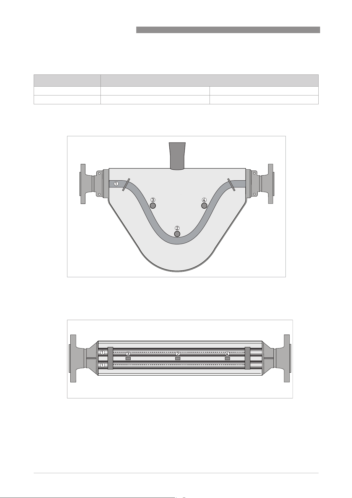
1.4 Measuring principle (twin tube)
Meter from the side, showing tube layout
OPTIMASS 6000
1 Measuring tubes
2 Drive coil
3 Sensor 1
4 Sensor 2
Static meter not energised and with no flow
1 Measuring tubes
2 Drive coil
3 Sensor 1
4 Sensor 2
A Coriolis twin tube mass flowmeter consists of two measuring tubes 1 a drive coil 2 and two
sensors (3 and 4) that are positioned either side of the drive coil.
6
www.krohne.com 10/2018 - 4001894104 - TD OPTIMASS 6000 R04 en
Page 7
OPTIMASS 6000
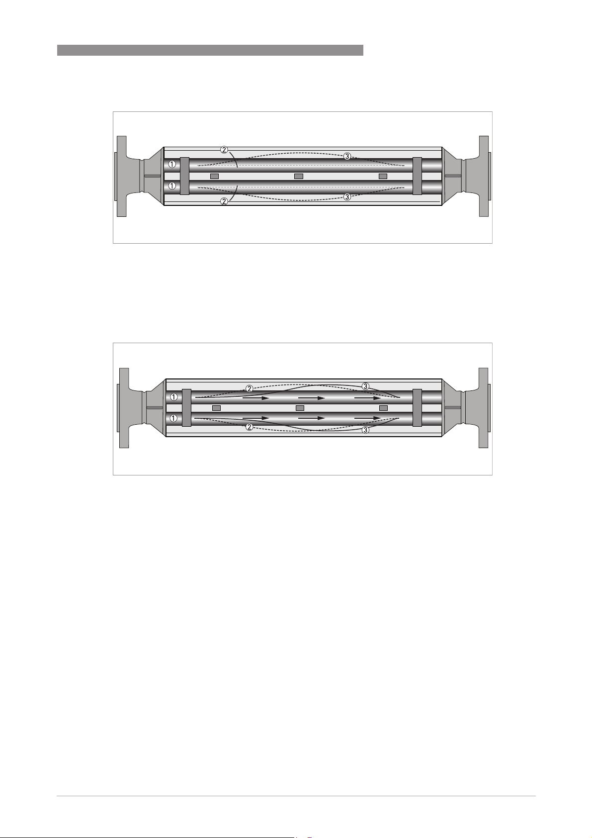
Energised meter
1 Measuring tubes
2 Direction of oscilation
3 Sine wave
When the meter is energised, the drive coil vibrates the measuring tubes causing them to
oscillate and produce a sine wave 3. The sine wave is monitored by the two sensors.
Energised meter with process flow
PRODUCT FEATURES
1
1 Process flow
2 Sine wave
3 Phase shift
When a fluid or gas passes through the tubes, the coriolis effect causes a phase shift in the sine
wave that is detected by the two sensors. This phase shift is directly proportional to the mass
flow.
Density measurement is made by evaluation of the frequency of vibration and temperature
measurement is made using a Pt500 sensor.
www.krohne.com10/2018 - 4001894104 - TD OPTIMASS 6000 R04 en
7
Page 8

2
TECHNICAL DATA
OPTIMASS 6000
2.1 Technical data
•
The following data is provided for general applications. If you require data that is more
relevant to your specific application, please contact us or your local sales office.
•
Additional information (certificates, special tools, software,...) and complete product
documentation can be downloaded free of charge from the website (Downloadcenter).
Measuring system
Measuring principle Coriolis mass flow
Application range Mass flow and density measurement of fluids, gases and solids
Measured values Mass, density, temperature
Calculated values Volume, referred density, concentration, velocity
Sensor model range
Sensor model range
Sensor model rangeSensor model range
Stainless Steel 316L 08...250 Compact / remote 100 barg @ 20°C / 1450 psig @ 68°F, temp. range
Hastelloy® 08...80
Duplex Stainless Steel 100...200 Compact / remote 200 barg @ 20°C / 2900 psig @ 68°F, temp. range
-70°C...+230°C / -94°F...+446°F
Remote only 100 barg @ 20°C / 1450 psig @ 68°F, temp. range
-50°C...+400°C / -58°F...+752°F
Compact / remote 100 barg @ 20°C / 1450 psig @ 68°F, temp. range
-200°C...+40°C / -364°F...+104°F
Compact / remote 200 barg @ 20°C / 2900 psig @ 68°F, temp. range
-70°C...+400°C / -58°F...+752°F
Compact / remote 200 barg @ 20°C / 2900 psig @ 68°F, temp. range
-50°C...+400°C / -58°F...+752°F
Remote only 200 barg @ 20°C / 2900 psig @ 68°F, temp. range
-196°C...+40°C / -364°F...+104°F
-50°C...+230°C / -58°F...+446°F
Design
Basic System consists of a measuring sensor and a converter to process the
Features Fully welded maintenance free sensor with twin V-shaped measuring tube
Variants
Variants
VariantsVariants
Compact version Integral converter
Remote version Available with a field version of the converter
output signal
Performance specification
Reference conditions
Reference conditions
Reference conditionsReference conditions
Calibration fluid Water
Calibration temperature +20°C / +68°F (± 5°C)
Calibration pressure 1...6 barg / 14.5...87 psig
Calibration rig Accreditation satisfies the requirements of BS EN ISO / IEC 17025
Mass flow (standard)
Mass flow (standard)
Mass flow (standard)Mass flow (standard)
Liquid flow rate ≥ zero stability × 1000
Base accuracy ±0.1% of actual measured flow rate
Repeatability Better than 0.05% of measured flow rate
Liquid flow rate < zero stability × 1000
Base accuracy ±zero stability (see zero stability below)
8
www.krohne.com 10/2018 - 4001894104 - TD OPTIMASS 6000 R04 en
Page 9

OPTIMASS 6000
Repeatability Better than zero stability × 0.5
Gas Better than 0.35% plus zero stability
Repeatability Better than 0.2% plus zero stability
Mass flow (optional)
Mass flow (optional)
Mass flow (optional)Mass flow (optional)
Liquid flow rate ≥ zero stability × 2000
Base accuracy 0.05% of measured flow rate
Repeatability Better than 0.025% of measured flow rate
Liquid flow rate < zero stability × 2000
Base accuracy ±zero stability
Repeatability Better than zero stability × 0.5
Zero stability
Zero stability
Zero stabilityZero stability
Meter size Standard temperature High temperature
08 < 0.03 kg/h < 0.48 kg/h
10 < 0.06 kg/h < 0.096 kg/h
15 < 0.19 kg/h < 0.304 kg/h
25 < 0.95 kg/h < 1.52 kg/h
50 < 1.75 kg/h < 2.80 kg/h
80 < 3.90 kg/h < 6.24 kg/h
100 < 8.75 kg/h < 14.00 kg/h
150 < 16.00 kg/h < 25.60 kg/h
200 < 27.50 kg/h < 44.00 kg/h
250 < 50.00 kg/h < 80.00 kg/h
Effect on sensor zero point caused by a deviation in process temperature from zero calibration temperature
Effect on sensor zero point caused by a deviation in process temperature from zero calibration temperature
Effect on sensor zero point caused by a deviation in process temperature from zero calibration temperatureEffect on sensor zero point caused by a deviation in process temperature from zero calibration temperature
Standard temperature range
All materials sizes 08...10 0.0010% of nominal flow per 1°C / 0.00056% of nominal flow per 1°F
All materials sizes 15...250 0.00075% of nominal flow per 1°C / 0.00042% of nominal flow per 1°F
High temperature range
All materials sizes 08...250 0.008% of nominal flow per 1°C / 0.0044% of nominal flow per 1°F
Pressure effect on mass flow rate
Pressure effect on mass flow rate
Pressure effect on mass flow ratePressure effect on mass flow rate
All materials sizes 08...50 -0.005% of reading per 1 barg / -0.00034 % per 1 psig
All materials sizes 80...100 -0.0055% of reading per 1 barg / -0.00038 % per 1 psig
All materials sizes 150...250 -0.008% of reading per 1 barg / -0.00055 % per 1 psig
Density
Density
DensityDensity
Measuring range
Base accuracy
Repeatability / on site calibration
Process temperature effect of deviation from calibration temperature
Process temperature effect of deviation from calibration temperature
Process temperature effect of deviation from calibration temperatureProcess temperature effect of deviation from calibration temperature
All materials / meter sizes Better than 0.015 g/l per 1°C / 0.0083 g/l per 1°F
100...3000 kg/m3 / 6...187 lb/ft
±1 kg/m3 / ±0.06 lb/ft
±0.3 kg/m3 / ±0.015 lb/ft
3
3
3
TECHNICAL DATA
2
www.krohne.com10/2018 - 4001894104 - TD OPTIMASS 6000 R04 en
9
Page 10

2
TECHNICAL DATA
OPTIMASS 6000
Pressure effect on density of deviation from calibration pressure (based on reference density = 1000 kg/m
Pressure effect on density of deviation from calibration pressure (based on reference density = 1000 kg/m
Pressure effect on density of deviation from calibration pressure (based on reference density = 1000 kg/mPressure effect on density of deviation from calibration pressure (based on reference density = 1000 kg/m
All materials size 08
All materials sizes 10…15
All materials sizes 25…80
All materials sizes 100…150
Volume flow
Volume flow
Volume flowVolume flow
Measurement error and repeatability calculations satisfy the requirements of BS ISO 10790 (most recent and up to date
version)
Temperature
Temperature
TemperatureTemperature
Measurement error ± 0.5°C ± 0.5% of reading / ±0.9°F ± 0.5% of reading
+0.038 kg/m3 per bar
+0.026 kg/m3 per bar
+0.017 kg/m3 per bar
+0.011 kg/m3 per bar
3333
)
Operating conditions
Nominal flow rates
Nominal flow rates (1 barg / 14.5 psig pressure drop)
Nominal flow ratesNominal flow rates
08 600 kg/h / 22 lb/min
10 1200 kg/h / 44 lb/min
15 3800 kg/h / 139 lb/min
25 19000 kg/h / 698 lb/min
50 35000 kg/h / 1286 lb/min
80 78000 kg/h / 2866 lb/min
100 175000 kg/h / 6430 lb/min
150 320000 kg/h / 11758 lb/min
200 550000 kg/h / 20209 lb/min
250 1000000 kg/h / 36743 lb/min
Assumes operating density 1000 kg/m3 / 62.4 lb/ft
For Hastelloy® meters, assume a pressure drop of 1.15 barg
Maximum flow rates
Maximum flow rates
Maximum flow ratesMaximum flow rates
All meters 150% of nominal flow rate
3
Environmental
Ambient temperature
Ambient temperature
Ambient temperatureAmbient temperature
Compact meter Standard converter SIL capable converter
Aluminium converter -40...+65°C / -40…+149°F -40...+55°C / -40…+131°F
Stainless Steel converter -40...+60°C / -40…+131°F -40...+55°C / -40…+131°F
Remote meter Standard converter SIL capable converter
Standard temperature range -40...+65°C / -40…+149°F -40...+55°C / -40…+131°F
Cryogenic temperature range -20...+65°C / -4…+149°F -40...+55°C / -40…+131°F
Hazardous Area versions Refer to temperature limits
Protection category (Acc. toEN 60529 IP 67, NEMA 4X
Vibration (acc IEC 60068-2-6)
10
10-150-10 Hz with 0.15 mm for 10...60 Hz, 20 m/s2 for 60…150 Hz
www.krohne.com 10/2018 - 4001894104 - TD OPTIMASS 6000 R04 en
Page 11

OPTIMASS 6000
Process temperatures
Process temperatures
Process temperaturesProcess temperatures
Standard temperature range (flange
connections)
Safe area -70…+230°C / -94…+446°F -70...+150°C / -94...+302°F
Hazardous area -50…+230°C / -58…+446°F -50°C...+150°C / -58...+302°F
High temperature range -50…+400°C / -58…+752°F N/A
Cryogenic temperature range -200…+40°C / -328…+104°F -200…+40°C / -328…+104°F
Standard temperature range (hygienic
connections)
Safe area -70…+150°C / -94…+302°F -70…+150°C / -94…+302°F
Hazardous area -50…+150°C / -58…+302°F -50…+150°C / -58…+302°F
Nominal pressure at 20
Nominal pressure at 20° C / 68
Nominal pressure at 20Nominal pressure at 20
Measuring tube
Measuring tube SS 316 / 316L Hastelloy® C22 / S31803
Measuring tubeMeasuring tube
FM / PED -1…100 barg / -14.5…1450 psig -1…200 barg / -14.5…2900 psig
CRN / ASME B31.3 -1…100 barg / -14.5…1450 psig Pending
Outer casing burst pressure
Outer casing burst pressure
Outer casing burst pressureOuter casing burst pressure
08 ≈ 100 barg
10
15
25
50 ≈ 70 barg
80
100 ≈ 10 barg
150
200
250
If the process temperature is higher than 20°C / 68°F, the burst pressure will be lower. For more information please
contact the manufacturer.
Fluid properties
Fluid properties
Fluid propertiesFluid properties
Permissible physical condition Liquids, gases, slurries
Permissible gas content (volume) Contact manufacturer for information.
Permissible solid content (volume) Contact manufacturer for information.
Installation conditions
Installation conditions
Installation conditionsInstallation conditions
Inlet / outlet runs None required
C / 68°FFFF
C / 68C / 68
1
Extended stem Short stem
Extended stem Short stem
TECHNICAL DATA
2
Materials
Stainless Steel (316 / 316L) meter
Stainless Steel (316 / 316L) meter
Stainless Steel (316 / 316L) meterStainless Steel (316 / 316L) meter
Measuring tubes / Flanges Stainless Steel AISI 316 / 316L (1.4401 / 1.4404) dual certified
Spigots Stainless Steel CF3M (1.4409)
Bridge AISI 316 / 316L (1.4401 / 1.4404) dual certified
Outer casing Stainless Steel AISI 316 / 316L (1.4401 / 1.4404) dual certified
Stainless Steel (S31803) meter
Stainless Steel (S31803) meter
Stainless Steel (S31803) meterStainless Steel (S31803) meter
Measuring tubes / Flanges Stainless Steel UNS 31803 (1.4462)
Spigots Stainless Steel J92205 (1.4470)
Bridge AISI 316 / 316L (1.4401 / 1.4404) dual certified
Outer casing Stainless Steel AISI 316 / 316L (1.4401 / 1.4404) dual certified
www.krohne.com10/2018 - 4001894104 - TD OPTIMASS 6000 R04 en
11
Page 12

2
TECHNICAL DATA
Hastelloy
Hastelloy® C22 meter
HastelloyHastelloy
Measuring tubes / raised face Hastelloy® C22
(Backing) flanges Stainless Steel AISI 316 / 316L (1.4401 / 1.4404) dual certified
Bridge Stainless Steel AISI 316 / 316L (1.4401 / 1.4404) dual certified
Outer casing Stainless Steel AISI 316 / 316L (1.4401 / 1.4404) dual certified
Heating jacket version
Heating jacket version
Heating jacket versionHeating jacket version
Heating loop and insulation jacket Stainless Steel AISI 316 (1.4401)
All versions
All versions
All versionsAll versions
Junction box (remote version) Die-cast Aluminium (polyurethane coating)
C22 meter
C22 meter C22 meter
Optional Stainless Steel 316 (1.4401)
OPTIMASS 6000
Process connections
Flange
Flange
FlangeFlange
DIN DN10…300 / PN16…160
ASME ½...12" / ASME 150…1500
JIS 10A...300A / 10...20K (10K maximum allowable temperature 300°C / 572°F)
Hygienic
Hygienic
HygienicHygienic
Tri-clover ¾...4"
Tri-clamp DIN 32676 DN15..100
Tri-clamp ISO 2852 1...4"
DIN 11864-2 Form A DN15...100
Male thread DIN 11851 DN15...100
Male thread SMS 25...100 mm / 1...4"
Electrical connections
Electrical connections For full details, including: power supply, power consumption etc., see
I/O For full details of I/O options, including data streams and protocols, see
technical data for the relevant signal converter.
technical data for the relevant signal converter.
Approvals
CE The device fulfils the statutory requirements of the CE directive. The
CRN acc to: ASME B31.3 (most recent and up to date version)
NACE MR0175 / ISO 15156 ("Sulphide Stress Corrosion Cracking Resistant Metallic
Custody transfer Measuring Instruments Directive (MID) MI 002 and MI 005 (most recent and
Functional safety SIL2 / SIL3 (acc to: IEC 61508)
manufacturer certifies that these requirements have been met by applying
the CE mark.
Materials for Oil Field Equipment") and MR0103 ("Materials Resistant to
Sulfide Stress Cracking in Corrosive Petroleum Refining Environments")
(most recent and up to date versions)
up to date version)
OIML R117-1
OIML R137
Compliant with API and AGA
12
www.krohne.com 10/2018 - 4001894104 - TD OPTIMASS 6000 R04 en
Page 13

OPTIMASS 6000
ATEX (most recent and up to date version)
ATEX (most recent and up to date version)
ATEX (most recent and up to date version)ATEX (most recent and up to date version)
OPTIMASS 6400C non Ex i signal outputs
OPTIMASS 6400C non Ex i signal outputs
OPTIMASS 6400C non Ex i signal outputsOPTIMASS 6400C non Ex i signal outputs
Ex d connection compartment II 1/2 G Ex db ia IIC T6...T1 Ga/Gb
II 2 D Ex tb IIIC T270°C Db
Ex e connection compartment II 1/2 G Ex db eb ia IIC T6...T1 Ga/Gb
II 2 D Ex tb IIIC T270°C Db
OPTIMASS 6400C Ex i signal outputs
OPTIMASS 6400C Ex i signal outputs
OPTIMASS 6400C Ex i signal outputsOPTIMASS 6400C Ex i signal outputs
Ex d connection compartment II 1/2(1) G Ex db ia [ia Ga] IIC T6...T1 Ga/Gb
II 2(1) D Ex tb [ia Da] IIIC T270°C Db
Ex e connection compartment II 1/2(1) G Ex db eb ia [ia Ga] IIC T6...T1 Ga/Gb
II 2(1) D Ex tb [ia Da] IIIC T270°C Db
OPTIMASS 6000 / 6000F
OPTIMASS 6000 / 6000F II 1 G Ex ia IIC T6...T1 Ga
OPTIMASS 6000 / 6000FOPTIMASS 6000 / 6000F
II 1 D Ex ia IIIC T270°C Da
II 1 D Ex ia IIIC T440°C Da
1 For information only. Secondary pressure containment is NOT supplied on this meter
TECHNICAL DATA
2
ATEX temperature limits
OPTIMASS 6000 / 6000F with or without heating jacket / insulation
Ambient temp. T
-40...40 -50...40 T6 T80
-40...55 -50...40 T6 T80
-40...65 -50...40 T6 T80
Cryogenic version
Cryogenic version
Cryogenic versionCryogenic version
-20...65 -200...40 T6-T1 T80
OPTIMASS 6400C with aluminium converter housing, with or without heating jacket / insulation
-40...40 -50...40 T6 T80
-40...50 -50...40 T6 T80
-40...65 -50...65 T4-T1 T105
Cryogenic version
Cryogenic version
Cryogenic versionCryogenic version
-40...65 -200...40 T6-T1 T80
OPTIMASS 6400C with SS converter housing, with or without heating jacket / insulation
-40...40 -50...40 T6 T80
°C Medium temp. Tm °C Temp. class Max. Surface temp. °C
amb
-50...150 T3 T190
-50...230 T2-T1 T270
-50...150 T3 T190
-50...230 T2-T1 T270
-50...150 T3 T190
-50...230 T2-T1 T270
-50...150 T3 T190
-50...230 T2-T1 T270
-50...150 T3 T190
-50...230 T2-T1 T270
-50...150 T3 T190
-50...230 T2-T1 T270
www.krohne.com10/2018 - 4001894104 - TD OPTIMASS 6000 R04 en
13
Page 14

2
TECHNICAL DATA
-40...50 -50...40 T6 T80
-50...150 T3 T190
-50...230 T2-T1 T270
-40...60 -50...60 T4-T1 T100
Cryogenic version
Cryogenic version
Cryogenic versionCryogenic version
-25...+60 -200...40 T6-T1 T80
High temperature versions
High temperature versions
High temperature versionsHigh temperature versions
OPTIMASS 6000F - HT with aluminium junction box, heating jacket and insulation
-40...40 -50...40 T6 T80
-50...230 T2 T270
-50...400 T1 T440
-40...55 -50...40 T6 T80
-50...230 T2 T270
-50...400 T1 T440
-40...60 -50...40 T6 T80
-50...230 T2 T270
-50...400 T1 T440
-40...65 -50...350 T1 T390
OPTIMASS 6000F - HT with SS junction box, heating jacket and insulation
-40...40 -50...40 T6 T80
-50...230 T2 T270
-50...400 T1 T440
-40...50 -50...40 T6 T80
-50...230 T2 T270
-50...400 T1 T440
-40...55 -50...40 T6 T80
-50...230 T2 T270
-50...400 T1 T440
-40...60 -50...350 T1 T390
OPTIMASS 6000F - HT with aluminium or SS junction box, insulation but no heating jacket
-40...40 -50...40 T6 T80
-50...230 T2 T270
-50...400 T1 T440
-40...55 -50...40 T6 T80
-50...230 T2 T270
-50...400 T1 T440
-40...65 -50...40 T6 T80
-50...230 T2 T270
-50...400 T1 T440
OPTIMASS 6000
14
www.krohne.com 10/2018 - 4001894104 - TD OPTIMASS 6000 R04 en
Page 15

OPTIMASS 6000
Maximum end loadings (Stainless Steel 316 / 316L)
TECHNICAL DATA
2
S08 /
S15 S25 S50 S80 S100 S150 S200 S250
S10
Flanges
Flanges
FlangesFlanges
20°C 40 barg 15 kN 25 kN 38 kN 48 kN 99 kN 130 kN 250 kN 300 kN 350 kN
100 barg 12 kN 17 kN 19 kN 15 kN 20 kN 100 kN 120 kN 150 kN 200 kN
230°C 32 barg 7 kN 12 kN 18 kN 25 kN 45 kN 60 kN 50 kN 100 kN 150 kN
60 barg 5 kN 20 kN
400°C 27.4 barg 5 kN 6 kN 10 kN 12 kN 20 kN 50 kN 80 kN 100 kN 150 kN
40 barg 4 kN 5 kN 20 kN
Hygienic (all connections)
Hygienic (all connections)
Hygienic (all connections)Hygienic (all connections)
150°C 10 barg 5 kN 9 kN 12 kN 12 kN 18 kN 21 kN N/A N/A N/A
140°C 40 barg 3 kN 5 kN 5 kN N/A N/A N/A N/A N/A N/A
25 barg N/A N/A N/A 9 kN N/A N/A N/A N/A N/A
16 barg N/A N/A N/A N/A 12 kN 12 kN N/A N/A N/A
Heating jacket connections
Heating jacket connections
Heating jacket connectionsHeating jacket connections
1
1 All temperature and pressure ranges
0 kN 0 kN 0 kN 0 kN 0 kN 0 kN 0 kN 0 kN 0 kN
Maximum end loadings (Hastelloy® and Stainless Steel UNS S31803)
H08 /
H10
H15 H25 H50 H80 D100 D150 D200
Flanges (not including CRN)
Flanges (not including CRN)
Flanges (not including CRN)Flanges (not including CRN)
20°C 200 barg 12 kN 17 kN 19 kN 15 kN 20 kN 100 kN 120 kN
230°C 145 barg 5 kN 20 kN
Flanges (CRN regions)
Flanges (CRN regions)
Flanges (CRN regions)Flanges (CRN regions)
20°C 200 barg
230°C 145 barg
Heating jacket connections
Heating jacket connections
Heating jacket connectionsHeating jacket connections
3
1 D200 limited to 180 barg at 20°C
2 D100 and D150 limited to 120 barg at 230°C. D200 limited to 110 barg at 230°C
3 All temperature and pressure ranges
1
2
12 kN 17 kN 19 kN 15 kN 20 kN 60 kN 30 kN 10 kN
5 kN 20 kN
0 kN 0 kN 0 kN 0 kN 0 kN 0 kN 0 kN 0 kN
• DN08...50 (axial) loads have been calculated, based on 316L schedule 40 process pipework,
where un-radiographed butt welds have been used in pipe joints.
• DN80...250 (axial) loads have been calculated, based on 316L schedule 80 process pipework,
where un-radiographed butt welds have been used in pipe joints.
• The loads shown are the maximum permitted static load. If loads are cycling (between
tension and compression) these loads should be reduced. For advice, consult the
manufacturer.
www.krohne.com10/2018 - 4001894104 - TD OPTIMASS 6000 R04 en
15
Page 16

2
TECHNICAL DATA
2.2 Guidelines for maximum operating pressure
Always make sure that the meter is used within its operating limits.
Pressure / temperature de-rating (metric) for meters with SS 316 measuring tubes.
Pressure / temperature de-rating (metric) for meters with SS 316 measuring tubes.
Pressure / temperature de-rating (metric) for meters with SS 316 measuring tubes. Pressure / temperature de-rating (metric) for meters with SS 316 measuring tubes.
Standard temperature range.
Standard temperature range.
Standard temperature range.Standard temperature range.
OPTIMASS 6000
Figure 2-1: Measuring tube PED certification
X temperature [°C]
Y pressure [barg]
Pressure / temperature de-rating (imperial) for meters with SS 316 measuring tubes.
Pressure / temperature de-rating (imperial) for meters with SS 316 measuring tubes.
Pressure / temperature de-rating (imperial) for meters with SS 316 measuring tubes. Pressure / temperature de-rating (imperial) for meters with SS 316 measuring tubes.
Standard temperature range.
Standard temperature range.
Standard temperature range.Standard temperature range.
16
Figure 2-2: Measuring Tube PED certification
X temperature [°F]
Y pressure [psig]
www.krohne.com 10/2018 - 4001894104 - TD OPTIMASS 6000 R04 en
Page 17

OPTIMASS 6000
Pressure / temperature de-rating (metric) for meters with SS 316 and Hastelloy
Pressure / temperature de-rating (metric) for meters with SS 316 and Hastelloy®C22,
Pressure / temperature de-rating (metric) for meters with SS 316 and HastelloyPressure / temperature de-rating (metric) for meters with SS 316 and Hastelloy
PED certified measuring tubes. High temperature range.
PED certified measuring tubes. High temperature range.
PED certified measuring tubes. High temperature range.PED certified measuring tubes. High temperature range.
TECHNICAL DATA
C22,
C22, C22,
2
X temperature [°C]
Y pressure [barg]
1 Hastelloy® C22 08...80
2 Stainless Steel 316 08...250
Pressure / temperature de-rating (imperial) for meters with SS 316 and Hastelloy
Pressure / temperature de-rating (imperial) for meters with SS 316 and Hastelloy®
Pressure / temperature de-rating (imperial) for meters with SS 316 and HastelloyPressure / temperature de-rating (imperial) for meters with SS 316 and Hastelloy
C22, PED certified measuring tubes. High temperature range.
C22, PED certified measuring tubes. High temperature range.
C22, PED certified measuring tubes. High temperature range.C22, PED certified measuring tubes. High temperature range.
X temperature [°F]
Y pressure [psig]
1 Hastelloy® C22 08...80
2 Stainless Steel 316 08...250
www.krohne.com10/2018 - 4001894104 - TD OPTIMASS 6000 R04 en
17
Page 18

2
TECHNICAL DATA
Pressure / temperature de-rating (metric) for meters with SS 31803 and Hastelloy
Pressure / temperature de-rating (metric) for meters with SS 31803 and Hastelloy®
Pressure / temperature de-rating (metric) for meters with SS 31803 and HastelloyPressure / temperature de-rating (metric) for meters with SS 31803 and Hastelloy
C22, PED certified measuring tubes. Standard temperature range
C22, PED certified measuring tubes. Standard temperature range
C22, PED certified measuring tubes. Standard temperature rangeC22, PED certified measuring tubes. Standard temperature range
OPTIMASS 6000
X temperature [°C]
Y pressure [barg]
1 PED / CRN H08...80
2 CRN D100...150
3 CRN D200
Pressure / temperature de-rating (imperial) for meters with SS 31803 and Hastelloy
Pressure / temperature de-rating (imperial) for meters with SS 31803 and Hastelloy®
Pressure / temperature de-rating (imperial) for meters with SS 31803 and HastelloyPressure / temperature de-rating (imperial) for meters with SS 31803 and Hastelloy
C22, PED certified measuring tubes. Standard temperature range.
C22, PED certified measuring tubes. Standard temperature range.
C22, PED certified measuring tubes. Standard temperature range.C22, PED certified measuring tubes. Standard temperature range.
18
X temperature [°F]
Y pressure [psig]
1 PED / CRN H08...80
2 CRN D100...150
3 CRN D200
www.krohne.com 10/2018 - 4001894104 - TD OPTIMASS 6000 R04 en
Page 19

OPTIMASS 6000
Pressure / temperature de-rating (metric) for meters with SS 316, PED certified
Pressure / temperature de-rating (metric) for meters with SS 316, PED certified
Pressure / temperature de-rating (metric) for meters with SS 316, PED certified Pressure / temperature de-rating (metric) for meters with SS 316, PED certified
measuring tubes. Cryogenic temperature range.
measuring tubes. Cryogenic temperature range.
measuring tubes. Cryogenic temperature range.measuring tubes. Cryogenic temperature range.
TECHNICAL DATA
2
X temperature [°C]
Y pressure [barg]
Pressure / temperature de-rating (imperial) for meters with SS 316 measuring tubes
Pressure / temperature de-rating (imperial) for meters with SS 316 measuring tubes
Pressure / temperature de-rating (imperial) for meters with SS 316 measuring tubes Pressure / temperature de-rating (imperial) for meters with SS 316 measuring tubes
PED certified. Cryogenic temperature range.
PED certified. Cryogenic temperature range.
PED certified. Cryogenic temperature range.PED certified. Cryogenic temperature range.
X temperature [°F]
Y pressure [psig]
www.krohne.com10/2018 - 4001894104 - TD OPTIMASS 6000 R04 en
19
Page 20

2
TECHNICAL DATA
Pressure / temperature de-rating (metric) for meters with Hastelloy
Pressure / temperature de-rating (metric) for meters with Hastelloy®C22, PED
Pressure / temperature de-rating (metric) for meters with HastelloyPressure / temperature de-rating (metric) for meters with Hastelloy
certified measuring tubes. Cryogenic temperature range.
certified measuring tubes. Cryogenic temperature range.
certified measuring tubes. Cryogenic temperature range.certified measuring tubes. Cryogenic temperature range.
OPTIMASS 6000
C22, PED
C22, PED C22, PED
X temperature [°C]
Y pressure [barg]
Pressure / temperature de-rating (imperial) for meters with Hastelloy
Pressure / temperature de-rating (imperial) for meters with Hastelloy® C22, PED
Pressure / temperature de-rating (imperial) for meters with HastelloyPressure / temperature de-rating (imperial) for meters with Hastelloy
certified measuring tubes. Cryogenic temperature range.
certified measuring tubes. Cryogenic temperature range.
certified measuring tubes. Cryogenic temperature range.certified measuring tubes. Cryogenic temperature range.
X temperature [°F]
Y pressure [psig]
C22, PED
C22, PED C22, PED
20
Flanges
• DIN flange ratings are based on EN 1092-1 2007 table G.4.1 material group 14EO
• ASME flange ratings are based on ASME B16.5 2003 table 2 material group 2.2
• JIS flange ratings are based on JIS 2220: 2001 table 1 division 1 material group 022a
• JIS 10K flanges are limited to a maximum temperature of 300°C / 572°F
www.krohne.com 10/2018 - 4001894104 - TD OPTIMASS 6000 R04 en
Page 21

OPTIMASS 6000
Pressure / temperature de-rating (metric) for meters with hygienic connections.
Pressure / temperature de-rating (metric) for meters with hygienic connections.
Pressure / temperature de-rating (metric) for meters with hygienic connections.Pressure / temperature de-rating (metric) for meters with hygienic connections.
X temperature [°C]
Y pressure [barg]
1 SMS 1...1½", DIN 11851 DN10...40
2 SMS 2", Tri-clamp DN10...40, DIN 11864-2 DN10...40, DIN 11851 DN50...65
3 SMS 3", Tri-clamp DN50...65, DIN11864-2, DIN11864-2 DN50...100, DN11851 DN80...100
4 SMS 4", Tri-clamp DN80...100
TECHNICAL DATA
2
Pressure / temperature de-rating (imperial) for meters with hygienic connections.
Pressure / temperature de-rating (imperial) for meters with hygienic connections.
Pressure / temperature de-rating (imperial) for meters with hygienic connections.Pressure / temperature de-rating (imperial) for meters with hygienic connections.
X temperature [°F]
Y pressure [psig]
1 SMS 1...1½", DIN 11851 DN10...40
2 SMS 2", Tri-clamp DN10...40, DIN 11864-2 DN10...40, DIN 11851 DN50...65
3 SMS 3", Tri-clamp DN50...65, DIN11864-2, DIN11864-2 DN50...100, DN11851 DN80...100
4 SMS 4", Tri-clamp DN80...100
www.krohne.com10/2018 - 4001894104 - TD OPTIMASS 6000 R04 en
21
Page 22

2
TECHNICAL DATA
Notes
• The maximum operating pressure will be either the flange / hygienic connection rating or the
measuring tube rating, WHICHEVER IS THE LOWER!
• For hygienic applications above 10 bar, connection sizes DN25…100 / 1…4” are limited to the
measurement of liquid at the pressures shown in the above table.
• The maximum pressure for steam cleaning is 10 bar / 145 psi.
• For other applications above 10 bar / 145 psi, please contact the manufacturer.
• The manufacturer recommends that the seals are replaced at regular intervals. This will
maintain the hygienic integrity of the connection.
2.3 Dimensions and weights
2.3.1 Flanged versions
Meter weights
S08 S10 S15 S25 S50 S80 S100 S150 S200 S250
WHICHEVER IS THE LOWER!
WHICHEVER IS THE LOWER!WHICHEVER IS THE LOWER!
OPTIMASS 6000
kg
Aluminium (compact) 9.3 10.1 12.9 23.5 29.4 58.9 94.3 193.6 443.6 911.2
Stainless Steel (compact) 15.2 16 18.8 29.4 35.3 64.8 100.2 199.5 449.5 917.1
Aluminium (remote) 5.8 6.6 9.4 19.9 25.9 55.4 90.8 190.1 440 907.6
Stainless Steel (remote) 6.6 7.3 10.2 20.7 26.6 56.1 91.5 191.5 440.8 908.4
Heating jacket add 3.1 4.5 7 7.9 12.7 15.7 27.6 N/A
lbs
S08 S10 S15 S25 S50 S80 S100 S150 S200 S250
Aluminium (compact) 20.5 22.3 28.4 51.8 64.8 129.8 207.9 426.8 978 2008.8
Stainless Steel (compact) 33.5 35.3 41.4 64.8 77.8 142.9 220.9 440.7 991 2021.9
Aluminium (remote) 12.8 14.5 20.7 43.9 57.1 122.1 200.2 419.1 970 2001
Stainless Steel (remote) 14.55 16.1 22.5 45.6 58.6 123.7 201.7 422.2 971.8 2002.7
Heating jacket add 6.8 9.9 15.4 17.4 28 34.6 60.8 N/A
The weights shown are for meters fitted with PN40 flanges. Smaller or larger flange sizes will
affect the overall weight. For further information, please contact the manufacturer.
22
www.krohne.com 10/2018 - 4001894104 - TD OPTIMASS 6000 R04 en
Page 23

OPTIMASS 6000
Meter dimensions
TECHNICAL DATA
2
1 Compact version
2 Remote version
General dimensions
mm
S08 S10 S15 S25 S50 S80 S100 S150 S200 S250
A ±3 156 186 282 326 411 450 555 675 805
C 137
D 123.5
E1 ±3
1
E1 ±3
2
E2 ±3
3
E2 ±3
4
E2 ±3
5
F ±2 81 118 130 188 219 275 355 508
1 compact 150°C (short stem)
2 compact 230°C (extended stem)
3 remote 150°C (short stem)
4 remote 230°C (extended stem)
5 remote 400°C (extended stem)
289 290 307 342 369 394 436 512
375 376 393 428 455 480 522 598
209 210 230 262 289 314 356 432
295 296 316 348 375 400 442 518
335 336 353 388 415 440 482 558
www.krohne.com10/2018 - 4001894104 - TD OPTIMASS 6000 R04 en
23
Page 24

2
TECHNICAL DATA
OPTIMASS 6000
inches
S08 S10 S15 S25 S50 S80 S100 S150 S200 S250
A ±0.11 6.14 7.3 11.1 12.8 16.2 17.7 21.8 26.6 31.7
C 4.9
D 5.4
E1 ±0.12
E1 ±0.12
E2 ±0.12
E2 ±0.12
E2 ±0.12
F ±0.08 3.2 4.6 5.1 7.4 8.6 10.8 14 20
1 compact 302°F (short stem)
2 compact 446°F (extended stem)
3 remote 302°F (short stem)
4 remote 446°F(extended stem)
5 remote 752°F (extended stem)
1
2
3
4
5
11.4 11.4 12.0 13.5 14.5 15.5 17.2 20.2
14.8 14.8 15.5 16.8 17.9 18.9 20.5 23.5
8.2 8.3 9.0 10.3 11.4 12.4 10.0 17.0
11.6 11.6 12.4 13.7 14.8 15.7 17.4 20.4
13.2 13.2 13.9 15.3 16.3 17.3 19 22
Dimension B for meters with Stainless Steel measuring tubes
mm (±5)
S08 S10 S15 S25 S50 S80 S100 S150 S200 S250
PN16
PN16
PN16PN16
DN80 - - - - - - 970 - - -
DN100 - - - - - - 1000 1204 - -
DN150 - - - - - - - 1200 1572 -
DN200 - - - - - - - - 1586 -
DN250 - - - - - - - - - 2100
DN300 - - - - - - - - - 2026
PN40
PN40
PN40PN40
DN10 335 347 - - - - - - - -
DN15 341 353 510 - - - - - - -
DN25 - - 514 600 - - - - - -
DN40 - - - 610 709 - - - - -
DN50 - - - - 715 895 - - - -
DN80 - - - - - 915 986 - - -
DN100 - - - - - - 1000 1214 - -
DN150 - - - - - - - 1200 1589 -
DN200 - - - - - - - - 1638 -
DN250 - - - - - - - - - 2080
DN300 - - - - - - - - - 2100
PN63
PN63
PN63PN63
DN50 - - - - 743 923 - - - -
DN80 - - - - - 943 1014 - - -
DN100 - - - - - - 1026 1206 - -
24
www.krohne.com 10/2018 - 4001894104 - TD OPTIMASS 6000 R04 en
Page 25

OPTIMASS 6000
TECHNICAL DATA
mm (±5)
S08 S10 S15 S25 S50 S80 S100 S150 S200 S250
DN150 - - - - - - - 1240 1652 -
DN200 - - - - - - - - 1682 -
DN250 - - - - - - - - - 2120
DN300 - - - - - - - - - 2150
PN100
PN100
PN100PN100
DN10 355 367 - - - - - - - -
DN15 355 367 524 - - - - - - -
DN25 - - 550 636 - - - - - -
DN40 - - - 644 743 - - - - -
DN50 - - - - 755 935 - - - -
DN80 - - - - - 955 1026 - - -
DN100 - - - - - - 1050 1230 - -
DN150 - - - - - - - 1280 1692 -
DN200 - - - - - - - - 1722 -
DN250 - - - - - - - - - 2184
DN300 - - - - - - - - - 2210
ASME 150
ASME 150
ASME 150ASME 150
½¨ 361 373 530 - - - - - - -
¾¨ - - 540 - - - - - - -
1¨ - - 546 632 - - - - - -
1½¨ - - - 644 743 - - - - -
2¨ - - - - 747 926 - - - -
3¨ - - - - - 939 1010 - - -
4¨ - - - - - - 1022 1202 - -
6¨ - - - - - - - 1228 1640 -
8¨ - - - - - - - - 1666 -
10¨ - - - - - - - - - 2074
12¨ - - - - - - - - - 2100
ASME 300
ASME 300
ASME 300ASME 300
½¨ 371 383 540 - - - - - - -
¾¨ - - 550 - - - - - - -
1¨ - - 558 644 - - - - - -
1½¨ - - - 658 757 - - - - -
2¨ - - - - 759 939 - - - -
3¨ - - - - - 957 1028 - - -
4¨ - - - - - - 1042 1222 - -
6¨ - - - - - - - 1246 1658 -
8¨ - - - - - - - - 1686 -
10¨ - - - - - - - - - 2106
12¨ - - - - - - - - - 2132
2
www.krohne.com10/2018 - 4001894104 - TD OPTIMASS 6000 R04 en
25
Page 26

2
TECHNICAL DATA
OPTIMASS 6000
mm (±5)
S08 S10 S15 S25 S50 S80 S100 S150 S200 S250
ASME 600
ASME 600
ASME 600ASME 600
½¨ 383 395 552 - - - - - - -
¾¨ - - 562 - - - - - - -
1¨ - - 572 658 - - - - - -
1½¨ - - - 674 773 - - - - -
2¨ - - - - 779 959 - - - -
3¨ - - - - - 977 1048 - - -
4¨ - - - - - - 1086 1266 - -
6¨ - - - - - - - 1298 1710 -
8¨ - - - - - - - - 1742 -
10¨ - - - - - - - - - 2186
12¨ - - - - - - - - - 2194
JIS 10K
JIS 10K
JIS 10KJIS 10K
50A - - - - 715 895 - - - -
80A - - - - - 915 986 - - -
100A - - - - - - 1022 1202 - -
150A - - - - - - - 1202 1652 -
200A - - - - - - - - 1666 -
250A - - - - - - - - - 2106
300A - - - - - - - - - 2124
JIS 20K
JIS 20K
JIS 20KJIS 20K
10A 341 353 - - - - - - - -
15A 341 353 510 - - - - - - -
25A - - 514 600 - - - - - -
40A - - - 610 709 - - - - -
50A - - - - 715 895 - - - -
80A - - - - - 915 986 - - -
100A - - - - - - 1022 1240 - -
150A - - - - - - - 1240 1652 -
200A - - - - - - - - 1666 -
250A - - - - - - - - - 2106
300A - - - - - - - - - 2124
inches (±0.2)
S08 S10 S15 S25 S50 S80 S100 S150 S200 S250
PN16
PN16
PN16PN16
DN80 - - - - - - 38.2 - - -
DN100 - - - - - - 39.3 45.4 - -
DN150 - - - - - - - 47.2 61.9 -
DN200 - - - - - - - - 62.4 -
26
www.krohne.com 10/2018 - 4001894104 - TD OPTIMASS 6000 R04 en
Page 27

OPTIMASS 6000
TECHNICAL DATA
inches (±0.2)
S08 S10 S15 S25 S50 S80 S100 S150 S200 S250
DN250 - - - - - - - - - 82.7
DN300 - - - - - - - - - 79.8
PN40
PN40
PN40PN40
DN10 13.2 13.7 - - - - - - - -
DN15 13.4 13.9 20.1 - - - - - - -
DN25 - - 20.2 23.6 - - - - - -
DN40 - - - 24 27.9 - - - - -
DN50 - - - - 28.1 35.2 - - - -
DN80 - - - - - 36 38.8 - - -
DN100 - - - - - - 39.4 46.4 - -
DN150 - - - - - - - 47.2 62.5 -
DN200 - - - - - - - - 64.5 -
DN250 - - - - - - - - - 81.9
DN300 - - - - - - - - - 82.7
PN63
PN63
PN63PN63
DN50 - - - - 29.2 36.3 - - - -
DN80 - - - - - 37.1 39.9 - - -
DN100 - - - - - - 40.4 47.5 - -
DN150 - - - - - - - 48.8 65 -
DN200 - - - - - - - - 66.2 -
DN250 - - - - - - - - - 83.5
DN300 - - - - - - - - - 84.6
PN100
PN100
PN100PN100
DN10 14 14.4 - - - - - - - -
DN15 14 14.4 20.6 - - - - - - -
DN25 - - 21.6 25 - - - - - -
DN40 - - - 25.3 29.2 - - - - -
DN50 - - - - 29.7 36.8 - - - -
DN80 - - - - - 37.6 40.4 - - -
DN100 - - - - - - 41.3 48.4 - -
DN150 - - - - - - - 50.4 66.6 -
DN200 - - - - - - - - 67.8 -
DN250 - - - - - - - - - 85.9
DN300 - - - - - - - - - 87
ASME 150
ASME 150
ASME 150ASME 150
½¨ 14.2 14.7 20.9 - - - - - - -
¾¨ - - 21.2 - - - - - - -
1¨ - - 21.5 24.9 - - - - - -
1½¨ - - - 25.3 29.2 - - - - -
2¨ - - - - 29.4 36.5 - - - -
3¨ - - - - - 37 39.8 - - -
2
www.krohne.com10/2018 - 4001894104 - TD OPTIMASS 6000 R04 en
27
Page 28

2
TECHNICAL DATA
OPTIMASS 6000
inches (±0.2)
S08 S10 S15 S25 S50 S80 S100 S150 S200 S250
4¨ - - - - - - 40.2 47.3 - -
6¨ - - - - - - - 48.3 64.6 -
8¨ - - - - - - - - 65.6 -
10¨ - - - - - - - - - 81.6
12¨ - - - - - - - - - 82.7
ASME 300
ASME 300
ASME 300ASME 300
½¨ 14.6 15.1 21.2 - - - - - - -
¾¨ - - 21.6 - - - - - - -
1¨ - - 22 25.3 - - - - - -
1½¨ - - - 25.9 29.8 - - - - -
2¨ - - - - 30 37 - - - -
3¨ - - - - - 37.7 40.5 - - -
4¨ - - - - - - 41 48.1 - -
6¨ - - - - - - - 49 65.3 -
8¨ - - - - - - - - 66.4 -
10¨ - - - - - - - - - 82.9
12¨ - - - - - - - - - 83.9
ASME 600
ASME 600
ASME 600ASME 600
½¨ 15.1 15.5 21.7 - - - - - - -
¾¨ - - 22.1 - - - - - - -
1¨ - - 22.5 25.9 - - - - - -
1½¨ - - - 26.5 30.4 - - - - -
2¨ - - - - 30.7 37.7 - - - -
3¨ - - - - - 38.5 41.2 - - -
4¨ - - - - - - 42.8 49.8 - -
6¨ - - - - - - - 51.1 67.3 -
8¨ - - - - - - - - 68.6 -
10¨ - - - - - - - - - 86
12¨ - - - - - - - - - 86.4
JIS 10K
JIS 10K
JIS 10KJIS 10K
50A - - - - 28.2 35.2 - - - -
80A - - - - - 36 38.8 - - -
100A - - - - - - 40.2 47.3 - -
150A - - - - - - - 47.3 65 -
200A - - - - - - - - 65.5 -
250A - - - - - - - - - 82.9
300A - - - - - - - - - 83.6
JIS 20K
JIS 20K
JIS 20KJIS 20K
10A 13.4 13.9 - - - - - - - -
15A 13.4 13.9 20 - - - - - - -
25A - - 20.2 23.6 - - - - - -
28
www.krohne.com 10/2018 - 4001894104 - TD OPTIMASS 6000 R04 en
Page 29

OPTIMASS 6000
TECHNICAL DATA
inches (±0.2)
S08 S10 S15 S25 S50 S80 S100 S150 S200 S250
40A - - - 24 27.9 - - - - -
50A - - - - 28.2 35.2 - - - -
80A - - - - - 36 38.8 - - -
100A - - - - - - 40.2 48.8 - -
150A - - - - - - - 48.8 65 -
200A - - - - - - - - 62.6 -
250A - - - - - - - - - 82.9
300A - - - - - - - - - 83.6
Dimension B for meters with Hastelloy® and Stainless Steel (UNS S31803) measuring tubes
mm
H08 H10 H15 H25 H50 H80 D100 D150 D200
PN40
PN40
PN40PN40
DN15 328 353 - - - - - - -
DN25 - - 510 - - - - - -
DN40 - - - 600 - - - - -
DN50 - - - - 715 - - - -
DN80 - - - - - 915 - - -
PN63
PN63
PN63PN63
DN50 - - - - 715 - - - -
DN80 - - - - - 915 - - -
PN100
PN100
PN100PN100
DN15 328 353 - - - - - - -
DN25 - - 510 - - - - - -
DN40 - - - 600 - - - - -
DN50 - - - - 715 - - - -
DN80 - - - - - 915 - - -
PN160
PN160
PN160PN160
DN15 328 353 - - - - - - -
DN25 - - 510 - - - - - -
DN40 - - - 600 - - - - -
DN50 - - - - 715 - - - -
DN80 - - - - - 915 1042 - -
DN100 - - - - - - 1070 1250 -
DN150 - - - - - - - 1306 1718
DN200 - - - - - - - - 1742
ASME 150
ASME 150
ASME 150ASME 150
½¨ 328 353 - - - - - - -
1¨ - - 510 - - - - - -
1½¨ - - - 600 - - - - -
2¨ - - - - 715 - - - -
2
www.krohne.com10/2018 - 4001894104 - TD OPTIMASS 6000 R04 en
29
Page 30

2
TECHNICAL DATA
OPTIMASS 6000
mm
H08 H10 H15 H25 H50 H80 D100 D150 D200
3¨ - - - - - 915 - - -
ASME 300
ASME 300
ASME 300ASME 300
½¨ 328 353 - - - - - - -
1¨ - - 510 - - - - - -
1½¨ - - - 600 - - - - -
2¨ - - - - 715 - - - -
3¨ - - - - - 915 - - -
ASME 600
ASME 600
ASME 600ASME 600
½¨ 335 361 - - - - - - -
1¨ - - 510 - - - - - -
1½¨ - - - 608 - - - - -
2¨ - - - - 722 - - - -
3¨ - - - - - 915 - - -
ASME 900
ASME 900
ASME 900ASME 900
1½¨ - - - 608 - - - - -
2¨ - - - - 722 - - - -
3¨ - - - - - 915 1086 - -
4¨ - - - - - - 1112 1292 -
6¨ - - - - - - - 1342 1754
8¨ - - - - - - - - 1798
ASME 1500
ASME 1500
ASME 1500ASME 1500
½¨ 335 361 - - - - - - -
1¨ - - 517 - - - - - -
1½¨ - - - 608 - - - - -
2¨ - - - - 722 - - - -
3¨ - - - - - 915 1118 - -
4¨ - - - - - - 1130 1310 -
6¨ - - - - - - - 1406 1818
8¨ - - - - - - - - 1900
JIS 10K
JIS 10K
JIS 10KJIS 10K
50A - - - - 715 - - - -
80A - - - - - 915 - - -
JIS 20K
JIS 20K
JIS 20KJIS 20K
15A 328 353 - - - - - - -
25A - - 510 - - - - - -
40A - - - 600 - - - - -
50A - - - - 715 - - - -
80A - - - - - 915 - - -
30
www.krohne.com 10/2018 - 4001894104 - TD OPTIMASS 6000 R04 en
Page 31

OPTIMASS 6000
TECHNICAL DATA
inches
H08 H10 H15 H25 H50 H80 D100 D150 D200
PN40
PN40
PN40PN40
DN15 12.9 13.9 - - - - - - -
DN25 - - 20.1 - - - - - -
DN40 - - - 23.6 - - - - -
DN50 - - - - 28.1 - - - -
DN80 - - - - - 36 - - -
PN63
PN63
PN63PN63
DN50 - - - - 28.1 - - - -
DN80 - - - - - 36 - - -
PN100
PN100
PN100PN100
DN15 12.9 13.9 - - - - - - -
DN25 - - 20.1 - - - - - -
DN40 - - - 23.6 - - - - -
DN50 - - - - 28.1 - - - -
DN80 - - - - - 36 - - -
PN160
PN160
PN160PN160
DN15 12.9 13.9 - - - - - - -
DN25 - - 20.1 - - - - - -
DN40 - - - 23.6 - - - - -
DN50 - - - - 28.1 - - - -
DN80 - - - - - 36 41 - -
DN100 - - - - - - 42.1 49.2 -
DN150 - - - - - - - 51.4 67.6
DN200 - - - - - - - - 68.6
ASME 150
ASME 150
ASME 150ASME 150
½¨ 12.9 13.9 - - - - - - -
1¨ - - 20.1 - - - - - -
1½¨ - - - 23.6 - - - - -
2¨ - - - - 28.1 - - - -
3¨ - - - - - 36 - - -
ASME 300
ASME 300
ASME 300ASME 300
½¨ 12.9 13.9 - - - - - - -
1¨ - - 20.1 - - - - - -
1½¨ - - - 23.6 - - - - -
2¨ - - - - 28.1 - - - -
3¨ - - - - - 36 - - -
ASME 600
ASME 600
ASME 600ASME 600
½¨ 13.2 14.2 - - - - - - -
1¨ - - 20.1 - - - - - -
1½¨ - - - 23.9 - - - - -
2¨ - - - - 28.4 - - - -
3¨ - - - - - 36 - - -
2
www.krohne.com10/2018 - 4001894104 - TD OPTIMASS 6000 R04 en
31
Page 32

2
TECHNICAL DATA
OPTIMASS 6000
inches
H08 H10 H15 H25 H50 H80 D100 D150 D200
ASME 900
ASME 900
ASME 900ASME 900
1½¨ - - - 23.9 - - - - -
2¨ - - - - 28.4 - - - -
3¨ - - - - - 36 42.7 - -
4¨ - - - - - - 43.7 50.9 -
6¨ - - - - - - - 52.7 69
8¨ - - - - - - - - 70.8
ASME 1500
ASME 1500
ASME 1500ASME 1500
½¨ 13.2 14.2 - - - - - - -
1¨ - - 20.3 - - - - - -
1½¨ - - - 23.9 - - - - -
2¨ - - - - 28.4 - - - -
3¨ - - - - - 36 44 - -
4¨ - - - - - - 44.5 51.6 -
6¨ - - - - - - - 55.3 71.6
8¨ - - - - - - - - 74.8
JIS 10K
JIS 10K
JIS 10KJIS 10K
50A - - - - 28.1 - - - -
80A - - - - - 36 - - -
JIS 20K
JIS 20K
JIS 20KJIS 20K
15A 12.9 13.9 - - - - - - -
25A - - 20.1 - - - - - -
40A - - - 23.6 - - - - -
50A - - - - 28.1 - - - -
80A - - - - - 36 - - -
32
www.krohne.com 10/2018 - 4001894104 - TD OPTIMASS 6000 R04 en
Page 33

OPTIMASS 6000
TECHNICAL DATA
2.3.2 NAMUR dimensions
The following face to face dimensions comply with NAMUR NE132
mm (±3)
S15 S25 S50 S80 S100 S150 S250
PN10
PN10
PN10PN10
DN250 - - - - - - 2100
PN16
PN16
PN16PN16
DN100 - - - - 1000 - -
DN150 - - - - - 1200 -
DN200 - - - - - - 2100
PN40
PN40
PN40PN40
DN 15 510 - - - - - -
DN 25 - 600 - - - - -
DN 50 - - 715 - - - -
DN 80 - - - 915 - - -
2
inches (±0.12)
S15 S25 S50 S80 S100 S150 S250
PN10
PN10
PN10PN10
DN250 - - - - - - 82.7
PN16
PN16
PN16PN16
DN100 - - - - 39.4 - -
DN150 - - - - - 47.2 -
DN200 - - - - - - 82.7
PN40
PN40
PN40PN40
DN 15 20.1 - - - - - -
DN 25 - 23.6 - - - - -
DN 50 - - 28.1 - - - -
DN 80 - - - 36 - - -
www.krohne.com10/2018 - 4001894104 - TD OPTIMASS 6000 R04 en
33
Page 34

2
TECHNICAL DATA
OPTIMASS 6000
2.3.3 Hygienic versions
Dimension B for meter sizes 08...100 with polished connections and sizes 08...50 with unpolished
connections
mm (±5)
S08 S10 S15 S25 S50 S80 S100
Tri-clover
Tri-clover
Tri-cloverTri-clover
½¨ 308 320 - - - - -
1¨ - - 477 - - - -
1½¨ - - - 601 - - -
2¨ - - - - 692 - -
3¨ - - - - - 859 -
4" - - - - - - 930
Tri-clamp DIN 32676
Tri-clamp DIN 32676
Tri-clamp DIN 32676Tri-clamp DIN 32676
DN15 301 313 - - - - -
DN25 - - 477 - - - -
DN40 - - - 582 - - -
DN50 - - - - 678 - -
DN80 - - - - - 855 -
DN100 - - - - - - 926
Tri-clamp ISO 2852
Tri-clamp ISO 2852
Tri-clamp ISO 2852Tri-clamp ISO 2852
1¨ - - 477 - - - -
1½¨ - - - 569 - - -
2¨ - - - - 668 - -
3¨ - - - - - 859 -
4" - - - - - - 930
DIN 11864-2 Form A (female)
DIN 11864-2 Form A (female)
DIN 11864-2 Form A (female)DIN 11864-2 Form A (female)
DN15 345 357 - - - - -
DN25 - - 514 - - - -
DN40 - - - 629 - - -
DN50 - - - - 725 - -
34
www.krohne.com 10/2018 - 4001894104 - TD OPTIMASS 6000 R04 en
Page 35

OPTIMASS 6000
TECHNICAL DATA
mm (±5)
S08 S10 S15 S25 S50 S80 S100
DN80 - - - - - 915 -
DN100 - - - - - - 986
Male thread DIN 11851
Male thread DIN 11851
Male thread DIN 11851Male thread DIN 11851
DN15 307 319 - - - - -
DN25 - - 492 - - - -
DN40 - - - 605 - - -
DN50 - - - - 705 - -
DN80 - - - - - 889 -
DN100 - - - - - - 978
Male thread SMS
Male thread SMS
Male thread SMSMale thread SMS
1¨ - - 477 - - - -
1½¨ - - - 604 - - -
2¨ - - - - 695 - -
3¨ - - - - - 859 -
4" - - - - - - 930
2
inches (±0.2)
S08 S10 S15 S25 S50 S80 S100
Tri-clover
Tri-clover
Tri-cloverTri-clover
½¨ 12.1 12.6 - - - - -
1¨ - - 18.8 - - - -
1½¨ - - - 23.7 - - -
2¨ - - - - 27.2 - -
3¨ - - - - - 33.8 -
4" - - - - - - 36.6
Tri-clamp DIN 32676
Tri-clamp DIN 32676
Tri-clamp DIN 32676Tri-clamp DIN 32676
DN15 11.8 12.3 - - - - -
DN25 - - 18.8 - - - -
DN40 - - - 22.9 - - -
DN50 - - - - 26.7 - -
DN80 - - - - - 33.7 -
DN100 - - - - - - 36.5
Tri-clamp ISO 2852
Tri-clamp ISO 2852
Tri-clamp ISO 2852Tri-clamp ISO 2852
1¨ - - 18.8 - - - -
1½¨ - - - 22.4 - - -
2¨ - - - - 26.3 - -
3¨ - - - - - 33.8 -
4" - - - - - - 36.6
www.krohne.com10/2018 - 4001894104 - TD OPTIMASS 6000 R04 en
35
Page 36

2
TECHNICAL DATA
OPTIMASS 6000
inches (±0.2)
S08 S10 S15 S25 S50 S80 S100
DIN 11864-2 Form A (female)
DIN 11864-2 Form A (female)
DIN 11864-2 Form A (female)DIN 11864-2 Form A (female)
DN15 13.6 14 - - - - -
DN25 - - 20.2 - - - -
DN40 - - - 24.8 - - -
DN50 - - - - 28.5 - -
DN80 - - - - - 36 -
DN100 - - - - - - 38.8
Male thread DIN 11851
Male thread DIN 11851
Male thread DIN 11851Male thread DIN 11851
DN15 12 12.5 - - - - -
DN25 - - 19.4 - - - -
DN40 - - - 23 - - -
DN50 - - - - 27.1 - -
DN80 - - - - - 35 -
DN100 - - - - - - 38.5
Male thread SMS
Male thread SMS
Male thread SMSMale thread SMS
1¨ - - 18.8 - - - -
1½¨ - - - 23.8 - - -
2¨ - - - - 27.4 - -
3¨ - - - - - 33.8 -
4" - - - - - - 36.6
Dimension B for meter sizes 80...100 with unpolished connections
mm (±5) inches (±0.2)
S80 S100 S80 S100
Tri-clover
Tri-clover
Tri-cloverTri-clover
3¨ 863 - 34 -
4" - 913 - 35.9
Tri-clamp DIN 32676
Tri-clamp DIN 32676
Tri-clamp DIN 32676Tri-clamp DIN 32676
DN80 867 - 34.1 -
DN100 - 926 - 36.5
Tri-clamp ISO 2852
Tri-clamp ISO 2852
Tri-clamp ISO 2852Tri-clamp ISO 2852
3¨ 863 - 34 -
4" - 913 - 35.9
DIN 11864-2 Form A (female)
DIN 11864-2 Form A (female)
DIN 11864-2 Form A (female)DIN 11864-2 Form A (female)
DN80 928 - 36.5 -
DN100 - 986 - 38.8
Male thread DIN 11851
Male thread DIN 11851
Male thread DIN 11851Male thread DIN 11851
DN80 901 - 35.5 -
DN100 - 978 - 38.5
36
www.krohne.com 10/2018 - 4001894104 - TD OPTIMASS 6000 R04 en
Page 37

OPTIMASS 6000
TECHNICAL DATA
mm (±5) inches (±0.2)
S80 S100 S80 S100
Male thread SMS
Male thread SMS
Male thread SMSMale thread SMS
3¨ 868 - 34.2 -
4" - 926 - 36.5
2
www.krohne.com10/2018 - 4001894104 - TD OPTIMASS 6000 R04 en
37
Page 38

2
TECHNICAL DATA
2.3.4 Heating jacket version
Meter sizes 08...100
OPTIMASS 6000
Meter sizes 150...250
General dimensions
S08 S10 S15 S25 S50 S80 S100 S150 S200 S250
mm
Heating connection size: PN40 DN15 or ASME 150 ½¨
A ±5.0 435 550 660 685 860 925 847 1135 1581
B ±3.0 283 440 542 565 741 806 1036 1408 1860
C ±3.0 100 130 210 230 320 340 493 506 614.5
D ±3.0 315 344 453 499 622 682 918 230 414
E ±3.0 198 221 316 356 451 486 688 857 952
F ±3.0 232 226 254 266 322 372 414 500 650
38
www.krohne.com 10/2018 - 4001894104 - TD OPTIMASS 6000 R04 en
Page 39

OPTIMASS 6000
TECHNICAL DATA
inches
S08 S10 S15 S25 S50 S80 S100 S150 S200 S250
Heating connection size: PN40 DN15 or ASME 150 ½¨
A ±0.2 17.1 21.6 26 26.7 33.8 36.4 33.3 44.7 62.2
B ±0.12 11.1 17.3 21.3 22.2 29.2 31.7 40.8 55.4 73.2
C ±0.12 3.9 5.1 8.3 9 12.6 13.4 19.4 19.9 24.2
D ±0.12 12.4 13.5 17.8 19.6 24.5 26.8 36.1 9.1 16.3
E ±0.12 7.8 8.7 12.4 14 17.7 19.1 27 33.7 37.5
F ±0.12 9.1 8.9 10 10.5 12.7 14.6 16.36 19.7 25.6
2
www.krohne.com10/2018 - 4001894104 - TD OPTIMASS 6000 R04 en
39
Page 40

2
TECHNICAL DATA
2.3.5 Purge port option
If the meter has been ordered with purge ports, it will be supplied with two ports: one on the
front and one on the rear.
OPTIMASS 6000
1 Front view
2 Rear view
Dimensions
mm
S08 S10 S15 S25 S50 S80 S100 S150 S200 S250
A 70 110 145 150 205 220 345 600 800
B 32 45 57 60 85 100 160 140
inches
S08 S10 S15 S25 S50 S80 S100 S150 S200 S250
A 2.7 4.3 5.7 5.9 8.1 8.7 13.6 23.6 31.5
B 1.3 1.8 2.2 2.4 3.3 3.9 6.3 5.5
40
www.krohne.com 10/2018 - 4001894104 - TD OPTIMASS 6000 R04 en
Page 41

OPTIMASS 6000
2.3.6 Burst disc option
Dimensions
TECHNICAL DATA
2
mm
S08 S10 S15 S25 S50 S80 S100 S150 S200 S250
A 76 92 135 57 74 175 195 220
B 38.5 62 0 0 0 0 0 60
inches
S08 S10 S15 S25 S50 S80 S100 S150 S200 S250
A 3.0 3.6 5.3 2.2 2.9 6.9 7.7 8.7
B 1.52 2.4 0 0 0 0 0 2.4
www.krohne.com10/2018 - 4001894104 - TD OPTIMASS 6000 R04 en
41
Page 42

3
INSTALLATION
3.1 Intended use
This mass flowmeter is designed for the direct measurement of mass flow rate, product density
and product temperature. Indirectly, it also enables the measurement of parameters like total
mass, concentration of dissolved substances and the volume flow. For use in hazardous areas,
special codes and regulations are also applicable and these are specified in a separate
documentation.
Responsibility for the use of the measuring devices with regard to suitability, intended use and
corrosion resistance of the used materials against the measured fluid lies solely with the
operator.
This device is a Group 1, Class A device as specified within CISPR11:2009. It is intended for use in
industrial environment. There may be potential difficulties in ensuring electromagnetic
compatibility in other environments, due to conducted as well as radiated disturbances.
The manufacturer is not liable for any damage resulting from improper use or use for other than
the intended purpose.
OPTIMASS 6000
3.2 Mounting restrictions
3.2.1 General installation principles
There are no special installation requirements but you should note the following
points:
• Support the weight of the meter as close to the meter body as possible.
• Mount the meter in such a way to avoid the build up of gas or liquid in the measuring tube.
• Straight runs either side of the meter are not required.
• The use of reducers and other fittings at flanges, including flexible hoses, is allowed but you
should take care to avoid cavitation.
• Avoid extreme pipe size reductions.
• Meters are not affected by crosstalk and can be mounted in series or in parallel.
• Avoid mounting the meter at the highest point in the pipeline where air / gas can collect.
42
www.krohne.com 10/2018 - 4001894104 - TD OPTIMASS 6000 R04 en
Page 43

OPTIMASS 6000
Mounting positions
INSTALLATION
3
1 The meter can be mounted at an angle but it is recommended that the flow is uphill.
2 Avoid mounting the meter with the flow running downhill because it can cause siphoning. If the meter has to be mount-
ed with the flow running downhill, install an orifice plate or control valve downstream of the meter to maintain backpressure.
3 Horizontal mounting with flow running left to right.
4 Avoid mounting meter with long vertical runs after the meter as it can cause cavitation. Where the installation includes
a vertical run after the meter, install an orifice plate or control valve downstream to maintain backpressure.
5 The meter can be mounted vertically but it is recommended that the flow is uphill.
6 Avoid mounting the meter vertically with the flow running downhill. This can cause siphoning. If the meter has to be
installed this way, install an orifice plate or control valve downstream to maintain backpressure.
Comprehensive installation guidance is provided in the Handbook
www.krohne.com10/2018 - 4001894104 - TD OPTIMASS 6000 R04 en
43
Page 44

K
K
K
KROHNE – Process instrumentation and measurement solutions
•
Flow
•
Level
•
Temperature
•
Pressure
•
Process Analysis
•
Services
© KROHNE 10/2018 - 4001894104 - TD OPTIMASS 6000 R04 en - Subject to change without notice.
Head Office KROHNE Messtechnik GmbH
Ludwig-Krohne-Str. 5
47058 Duisburg (Germany)
Tel.: +49 203 301 0
Fax: +49 203 301 10389
info@krohne.com
The current list of all KROHNE contacts and addresses can be found at:
www.krohne.com
 Loading...