

Page 1
Technical Datasheet
Technical Datasheet
OPTIMASS 3400
OPTIMASS 3400
OPTIMASS 3400OPTIMASS 3400
Technical DatasheetTechnical Datasheet
Sensor for mass flow
•
First choice for low flow applications
•
Certified secondary pressure containment
•
A common footprint for all three sizes, in Hastelloy ® or Stainless Steel
The documentation is only complete when used in combination with the relevant
documentation for the signal converter.
© KROHNE 09/2016 - 4004907701 - TD OPTIMASS 3400 R01 en
Page 2

CONTENTS
OPTIMASS 3400
1 Product features 3
1.1 The solution for low flow measurement .......................................................................... 3
1.2 Features and options........................................................................................................ 5
1.3 Meter / converter combinations....................................................................................... 6
1.4 Measuring principle (single Z tube) ................................................................................. 6
2 Technical data 8
2.1 Technical data................................................................................................................... 8
2.2 ATEX temperature limits................................................................................................ 11
2.3 Measuring accuracy ....................................................................................................... 12
2.4 Guidelines for maximum operating pressure................................................................ 13
2.5 Dimensions and weights ................................................................................................ 15
2.5.1 General dimensions .............................................................................................................. 15
2.5.2 NPT connections ................................................................................................................... 16
2.5.3 Flange connections............................................................................................................... 17
2.5.4 Hygienic connections ............................................................................................................ 18
2.5.5 Heating jacket version .......................................................................................................... 19
3 Installation 20
3.1 Intended use ................................................................................................................... 20
3.2 Plastic Inserts................................................................................................................. 20
3.3 Meter support ................................................................................................................. 21
3.4 Two hole mounting ......................................................................................................... 21
3.5 Horizontal mounting....................................................................................................... 22
3.6 Vertical mounting ........................................................................................................... 22
3.7 Self draining ................................................................................................................... 22
3.8 Purge ports..................................................................................................................... 24
4 Notes 25
2
www.krohne.com 09/2016 - 4004907701 - TD OPTIMASS 3400 R01 en
Page 3
OPTIMASS 3400
1.1 The solution for low flow measurement
The OPTIMASS 3400 is the cost effective solution for accurate measurement in a variety of
applications, where there is a low process flow.
Combined with the power of the MFC 400, the OPTIMASS 3400 will provide accurate
measurement of mass, volume, density and concentration.
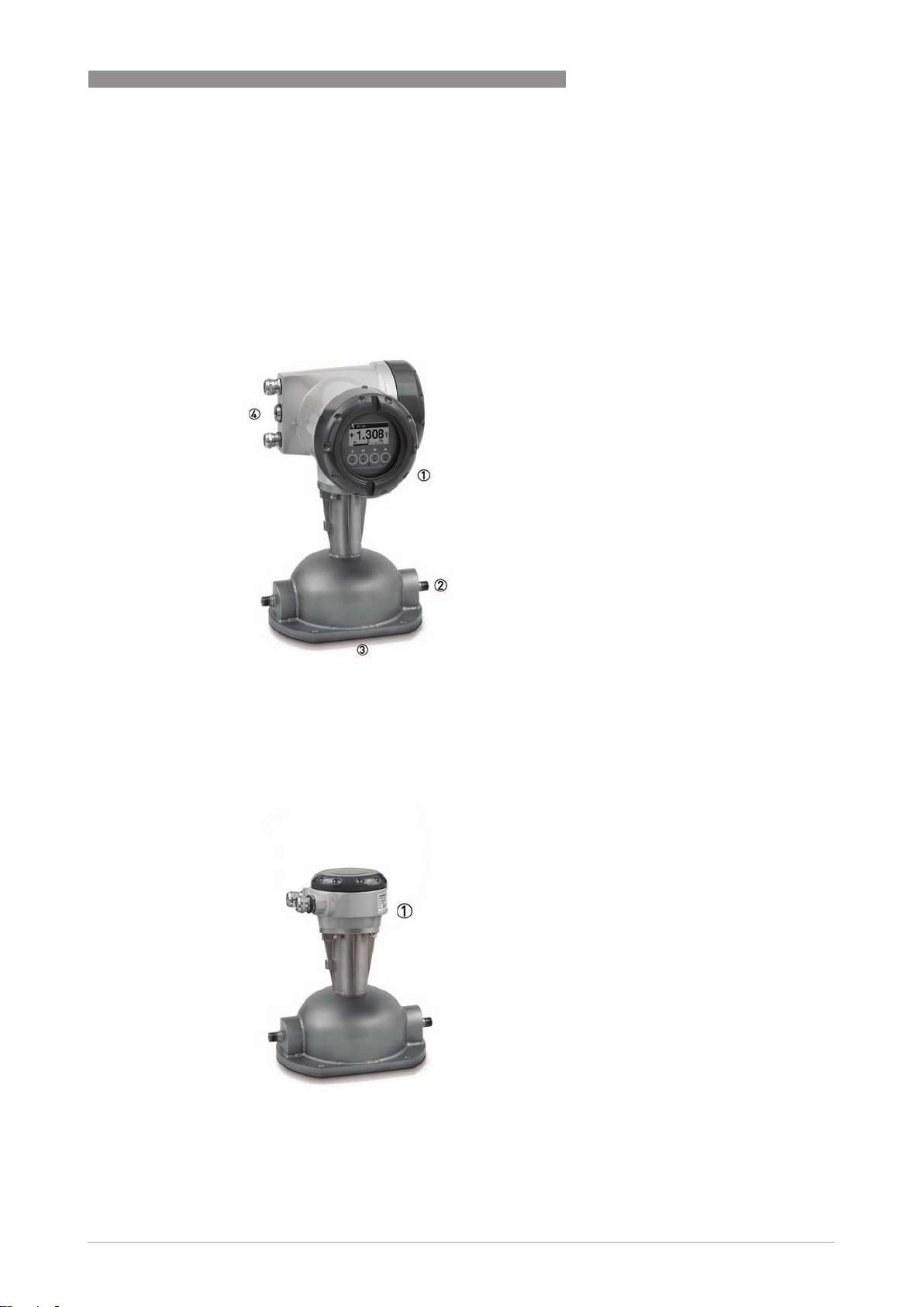
PRODUCT FEATURES
1
1 Comprehensive diagnostic capabilities.
2 Standard process connections available, including hygienic.
3 Certified secondary containment in Stainless Steel 316L.
4 Modular electronics with a range of output options (see separate documentation for details).
1 Remote terminal box.
www.krohne.com09/2016 - 4004907701 - TD OPTIMASS 3400 R01 en
3
Page 4

1
PRODUCT FEATURES
Features:
• Z-shaped measuring tube
• Easily drained and easy to clean
• Optional heating jacket
• Simple installation and start-up
• Modular electronics concept - electronics and sensor are easy to replace
• Data redundancy - accurate plug & play replacement of electronics
Industries:
• Wastewater
• Chemical
• Food & Beverage
• Paper & pulp
• Pharmaceutical
• Automotive
• Oil and gas
OPTIMASS 3400
Applications:
• Fragrance dispensing and high precision coatings in the pharmaceutical industry
• CO
• Natural gas and propane odorisation
• Engine test beds in the automotive industry
• Chemical injection
injection and dosing in the food and beverage industry
2
4
www.krohne.com 09/2016 - 4004907701 - TD OPTIMASS 3400 R01 en
Page 5
OPTIMASS 3400
1.2 Features and options
Features
PRODUCT FEATURES
• Low pressure loss, single Z tube design
guarantees a low pressure drop across the
meter.
• Self draining.
• Certified secondary containment.
• 150 barg / 2175 psig standard measuring tube.
• 300 barg / 4351 psig Hastelloy® measuring
tube.
• With advanced Entrained Gas Management
TM
(EGM
wide range of gas fractions and complex flow
conditions.
) the meter maintains operation over a
1
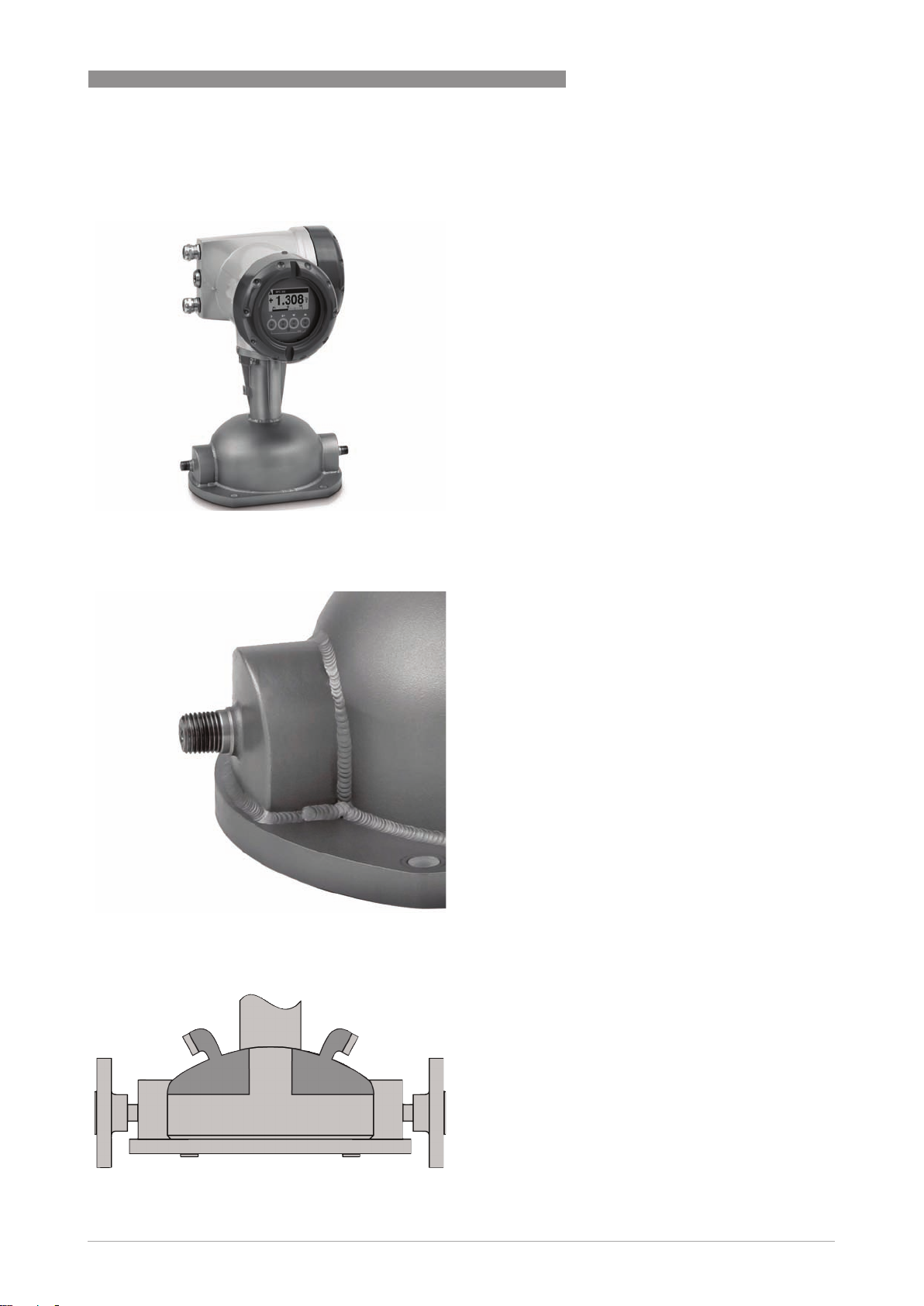
Connection options
Heating jacket & purge port
• NPT connections as standard.
• Also available with industry standard hygienic
connections.
• A range of flanges up to ASME 300 / PN40.
• Heating jacket option for use with temperature
dependant products.
• Prevents solidification of process product.
• Purge port option for protection in the event of
measuring tube failure.
• The purge port allows hazardous chemicals to
be drained away safely.
www.krohne.com09/2016 - 4004907701 - TD OPTIMASS 3400 R01 en
5
Page 6
1
PRODUCT FEATURES
1.3 Meter / converter combinations
Converter MFC 400
Configuration Compact Remote field
OPTIMASS 3400 3400C 3400F
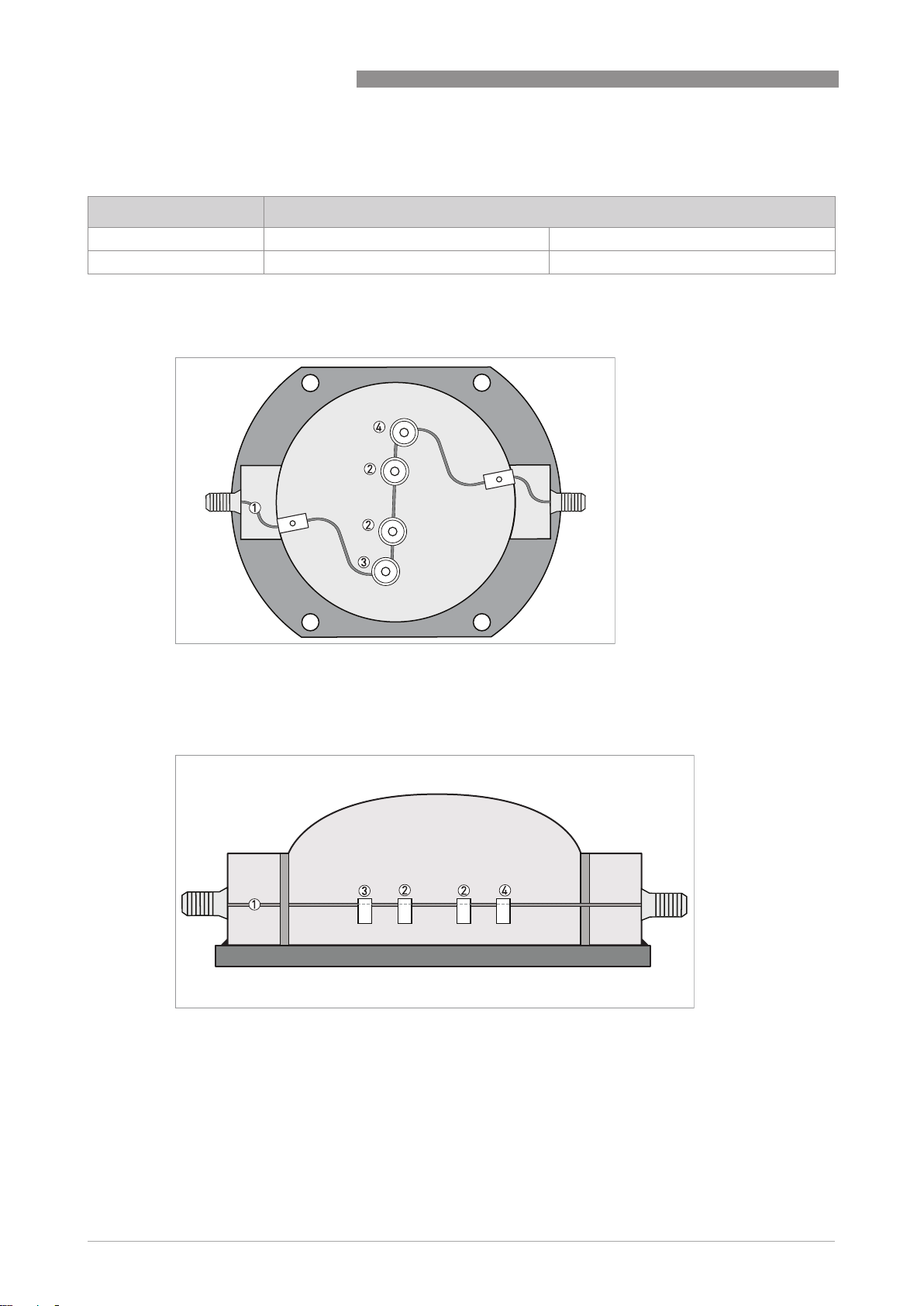
1.4 Measuring principle (single Z tube)
Meter tube layout, shown from above
OPTIMASS 3400
1 Measuring tube
2 Drive coils
3 Sensor 1
4 Sensor 2
Static meter not energised and with no flow
1 Measuring tube
2 Drive coils
3 Sensor 1
4 Sensor 2
A Coriolis single Z tube mass flowmeter consists of a single Z shaped measuring tube (1) two
drive coils (2) and two sensors (3 and 4) that are positioned either side of the drive coils.
6
www.krohne.com 09/2016 - 4004907701 - TD OPTIMASS 3400 R01 en
Page 7
OPTIMASS 3400
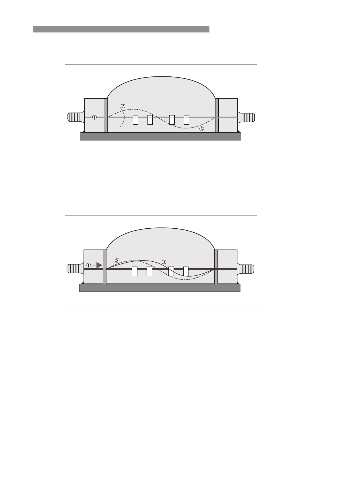
Energised meter
1 Measuring tube
2 Direction of oscilation
3 Sine wave
When the meter is energised, the drive coils vibrate the measuring tube causing it to oscillate
and produce a sine wave (3). The sine wave is monitored by the two sensors.
PRODUCT FEATURES
1
Energised meter with process flow
1 Process flow
2 Sine wave
3 Phase shift
When a fluid or gas passes through the tube, the Coriolis effect causes a phase shift in the sine
wave that is detected by the two sensors. This phase shift is directly proportional to the mass
flow.
Density measurement is made by evaluation of the frequency of vibration and temperature
measurement is made using a Pt500 sensor.
www.krohne.com09/2016 - 4004907701 - TD OPTIMASS 3400 R01 en
7
Page 8

2
TECHNICAL DATA
OPTIMASS 3400
2.1 Technical data
•
The following data is provided for general applications. If you require data that is more
relevant to your specific application, please contact us or your local sales office.
•
Additional information (certificates, special tools, software,...) and complete product
documentation can be downloaded free of charge from the website (Downloadcenter).
Measuring system
Measuring principle Coriolis mass flow
Application range Mass flow and density measurement of fluids, gases
Measured values Mass, density, temperature
Calculated values Volume, referred density, concentration, velocity
Design
Basic System consists of a measuring sensor and a converter to process the
Features Fully welded maintenance free sensor with single Z-shaped measuring tube
Variants
Variants
VariantsVariants
Compact version Integral converter
Remote version Available with field, wall or 19¨ rack mount versions of the converter
Modbus version Sensor with integral electronics providing Modbus output for connection to a
output signal
PLC
Measuring accuracy
Mass
Mass
MassMass
Liquid ±0.1% of actual measured flow rate + zero stability
Gas ±0.5% of actual measured flow rate + zero stability
Repeatability Better than 0.05% plus zero stability (includes the combined effects of
Zero stability
Zero stability
Zero stabilityZero stability
Stainless Steel / Hastelloy® 0.0057% of maximum flow rate with respective sensor size
Reference conditions
Reference conditions
Reference conditionsReference conditions
Product Water
Temperature +20°C / +68°F
Operating pressure 1 barg / 14.5 psig
Effect on sensor zero point caused by a shift in process temperature
Effect on sensor zero point caused by a shift in process temperature
Effect on sensor zero point caused by a shift in process temperatureEffect on sensor zero point caused by a shift in process temperature
Stainless Steel / Hastelloy® 0.0056% per 1°C / 0.0031% per 1°F
Effect on sensor zero point caused by a shift in process pressure
Effect on sensor zero point caused by a shift in process pressure
Effect on sensor zero point caused by a shift in process pressureEffect on sensor zero point caused by a shift in process pressure
Stainless Steel / Hastelloy® 0.013% of the max flow rate per 1 barg / 0.0009% of the max flow rate per 1
Density
Density
DensityDensity
Measuring range
Accuracy
On site calibration
repeatability, linearity and hysteresis)
psig
400...3000 kg/m3 / 25...187 lbs/ft
±2 kg/m3 / ±0.13 lbs/ft
±0.5 kg/m3 / ±0.033 lbs/ft
3
3
3
8
www.krohne.com 09/2016 - 4004907701 - TD OPTIMASS 3400 R01 en
Page 9

OPTIMASS 3400
Temperature
Temperature
TemperatureTemperature
Accuracy ±1°C / ±1.8°F
Operating conditions
Maximum flow rates
Maximum flow rates
Maximum flow ratesMaximum flow rates
01 20 kg/h / 0.733 lbs/min
03 130 kg/h / 4.766 lbs/min
04 450 kg/h / 16.5 lbs/min
Ambient temperature
Ambient temperature
Ambient temperatureAmbient temperature
Compact version with Aluminium
converter
Compact version with Stainless Steel
converter
Remote versions -40...+65°C / -40…+149°F
Process temperature
Process temperature
Process temperatureProcess temperature
Stainless Steel / Hastelloy® -40…+150°C / -40…+302°F
Nominal pressure at 20
Nominal pressure at 20°C / 68
Nominal pressure at 20Nominal pressure at 20
Measuring tube
Measuring tube
Measuring tubeMeasuring tube
Stainless Steel -1…150 barg / -14.5…2175 psig
Hastelloy® -1…300 barg / -14.5…4351 psig
Outer casing
Outer casing
Outer casingOuter casing
PED / CRN approved -1…30 barg / -14.5…435 psig
Fluid properties
Fluid properties
Fluid propertiesFluid properties
Permissible physical condition Liquids, gases
Permissible gas content (volume) Contact manufacturer for information.
Permissible solid content (volume) Contact manufacturer for information.
Protection category (acc. to EN 60529) IP 67, NEMA 4X
C / 68°F
C / 68C / 68
F
FF
-40...+60°C / -40…+140°F
Extended temperature range: 65°C / 149°F for some I/O options. For more
information contact manufacturer.
-40...+55°C / -40…+130°F
For operating pressures >30barg / 435psig, a burst disc is mandatory
TECHNICAL DATA
2
Installation conditions
Inlet runs None required
Outlet runs None required
Materials
Stainless Steel meter
Stainless Steel meter
Stainless Steel meterStainless Steel meter
Measuring tube Stainless Steel 316L (1.4435)
Process connections Stainless Steel 316L (1.4435)
Baseplate Stainless Steel 316L (1.4435)
Outer casing Stainless Steel 316L (1.4435)
Hastelloy
Hastelloy® meter
HastelloyHastelloy
Measuring tube Hastelloy® C-22
Process connections Hastelloy® C-22
Baseplate Stainless Steel 316L (1.4435)
Outer casing Stainless Steel 316L (1.4435)
meter
meter meter
www.krohne.com09/2016 - 4004907701 - TD OPTIMASS 3400 R01 en
9
Page 10

2
TECHNICAL DATA
Heating jacket version
Heating jacket version
Heating jacket versionHeating jacket version
Heating jacket Stainless Steel 316L (1.4435)
All versions
All versions
All versionsAll versions
Sensor electronics housing Stainless Steel 316L (1.4409)
Junction box (remote version) Die cast Aluminium (polyurethane coating)
Optional Stainless Steel 316 (1.4401)
Process connections
Threaded
Threaded
ThreadedThreaded
NPT-M ¼¨
Flange
Flange
FlangeFlange
DIN DN15 / PN40
ASME ½¨ / ASME 150…300
JIS 15A / 20K
Hygienic
Hygienic
HygienicHygienic
Tri-clover ½¨
Tri-clamp DIN 32676 DN10
OPTIMASS 3400
Electrical connections
Electrical connections For full details, including: power supply, power consumption etc., see
I/O For full details of I/O options, including data streams and protocols, see
technical data for the relevant converter.
technical data for the relevant converter.
Approvals
CE The device fulfils the statutory requirements of the CE directive. The
Factory Mutual / CSA Class I, Div 1 groups A, B, C, D
ANSI / CSA (Dual Seal) 12.27.901-2003
ATEX (most recent and up to date version)
ATEX (most recent and up to date version)
ATEX (most recent and up to date version)ATEX (most recent and up to date version)
OPTIMASS 3000 / 3000F (with or without heating jacket / insulation)
OPTIMASS 3000 / 3000F (with or without heating jacket / insulation)
OPTIMASS 3000 / 3000F (with or without heating jacket / insulation)OPTIMASS 3000 / 3000F (with or without heating jacket / insulation)
OPTIMASS 3400C Non Ex i signal outputs (with or without heating jacket / insulation)
OPTIMASS 3400C Non Ex i signal outputs (with or without heating jacket / insulation)
OPTIMASS 3400C Non Ex i signal outputs (with or without heating jacket / insulation)OPTIMASS 3400C Non Ex i signal outputs (with or without heating jacket / insulation)
Ex d connection compartment II 2 G Ex d ia IIC T6...T1 Gb
Ex e connection compartment II 2 G Ex de ia IIC T6...T1 Gb
manufacturer certifies that these requirements have been met by applying
the CE mark.
Class II, Div 1 groups E, F, G
Class III, Div 1 hazardous areas
Class I, Div 2 groups A, B, C, D
Class II, Div 2 groups F, G
Class III, Div 2 hazardous areas
II 1 G Ex ia IIC T6...T1 Ga
II 1 D Ex ia IIIC T165°C Da
II 2 D Ex tb IIIC T165°C Db
II 2 D Ex tb IIIC T165°C Db
10
www.krohne.com 09/2016 - 4004907701 - TD OPTIMASS 3400 R01 en
Page 11

OPTIMASS 3400
OPTIMASS 3400C Ex i signal outputs (with or without heating jacket / insulation)
OPTIMASS 3400C Ex i signal outputs (with or without heating jacket / insulation)
OPTIMASS 3400C Ex i signal outputs (with or without heating jacket / insulation)OPTIMASS 3400C Ex i signal outputs (with or without heating jacket / insulation)
Ex d connection compartment II 2(1) G Ex d ia [ia Ga] IIC T6...T1 Gb
II 2(1) D Ex tb [ia Da] IIIC T165°C Db
Ex e connection compartment II 2(1) G Ex de ia [ia Ga] IIC T6...T1 Gb
II 2(1) D Ex tb [ia Da] IIIC T165°C Db
2.2 ATEX temperature limits
TECHNICAL DATA
2
Optimass 3000 / 3000F with or without
heating jacket / insulation
Optimass 3400C Aluminium converter
housing, with or without heating jacket /
insulation
Optimass 3400C - Stainless Steel
converter housing, with or without
heating jacket / insulation
Ambient Temp.
T
°C
amb
-40...+40 40 T6 T55
-40...+50 70 T5 T85
-40...+65 90 T4 T105
Minimum medium temp: -50°C
-40...+40 40 T6 T55
-40...+50 90 T4 T105
-40...+65 65 T6-T1 T80
Minimum medium temp: -45°C
-40...+40 40 T6 T55
-40...+50 70 T5 T85
-40...+60 60 T6 - T1 T75
Minimum medium temp: -45°C
Max medium
Temp. T
70 T5 T85
90 T4 T105
150 T3 – T1 T165
90 T4 T105
150 T3-T1 T165
130 T3-T1 T145
70 T5 T85
90 T4 T105
150 T3 – T1 T165
145 T3-T1 T160
70 T5 T85
90 T4 T105
130 T3 - T1 T145
90 T4 - T1 T105
°C
m
Temp. Class Max. Surface
Temp. °C
www.krohne.com09/2016 - 4004907701 - TD OPTIMASS 3400 R01 en
11
Page 12

2
TECHNICAL DATA
2.3 Measuring accuracy
1.6
1.4
1.2
1.0
0.8
0.6
0.4
0.2
0
OPTIMASS 3400
X Fow rate [%]
Y Measuring error [%]
Measuring error
The measuring error is obtained from the combined effects of accuracy and zero stability.
Reference conditions
Product Water
Temperature +20°C / +68°F
Operating pressure 1 barg / 14.5 psig
12
www.krohne.com 09/2016 - 4004907701 - TD OPTIMASS 3400 R01 en
Page 13

OPTIMASS 3400
2.4 Guidelines for maximum operating pressure
Notes
• Ensure that the meter is used within its operating limits
• All hygienic process connections have a maximum operating rating of 10 barg at 130°C /
145 psig at 266°F
Pressure / temperature de-rating for all meter sizes / materials, in metric
Pressure / temperature de-rating for all meter sizes / materials, in metric
Pressure / temperature de-rating for all meter sizes / materials, in metricPressure / temperature de-rating for all meter sizes / materials, in metric
TECHNICAL DATA
2
X Temperature [°C]
Y Pressure [barg]
1 Hastelloy
2 Stainless Steel 316L measuring tube
3 Outer casing
®
C22 measuring tube
www.krohne.com09/2016 - 4004907701 - TD OPTIMASS 3400 R01 en
13
Page 14

2
TECHNICAL DATA
Pressure / temperature de-rating for all meter sizes / materials, in imperial
Pressure / temperature de-rating for all meter sizes / materials, in imperial
Pressure / temperature de-rating for all meter sizes / materials, in imperialPressure / temperature de-rating for all meter sizes / materials, in imperial
X Temperature [°F]
Y Pressure [psig]
OPTIMASS 3400
1 Hastelloy
2 Stainless Steel 316L measuring tube
3 Outer casing
®
HC22 measuring tube
Flanges
• DIN flange ratings are based on EN 1092-1 2001 table 18, 1% proof stress material group
14EO
• ASME flange ratings are based on ASME B16.5 2003 table 2 material group 2.2
• JIS flange ratings are based on JIS 2220: 2001 table 1 division 1 material group 022a
Notes
• The maximum operating pressure will be either the flange rating or the measuring tube
rating, WHICHEVER IS THE LOWER!
• The manufacturer recommends that the seals are replaced at regular intervals. This will
maintain the hygienic integrity of the connection.
WHICHEVER IS THE LOWER!
WHICHEVER IS THE LOWER!WHICHEVER IS THE LOWER!
14
www.krohne.com 09/2016 - 4004907701 - TD OPTIMASS 3400 R01 en
Page 15

OPTIMASS 3400
2.5 Dimensions and weights
2.5.1 General dimensions
TECHNICAL DATA
2
Meter weights for Hastelloy® (H) and Stainless Steel (S)
Weight [kg]
H/S 01 H/S 03 H/S 04
Aluminium (compact) 16 16 16
Stainless Steel (compact) 22.1 22.1 22.1
Aluminium (remote) 13.2 13.2 13.2
Stainless Steel (remote) 14 14 14
Weight [lbs]
H/S 01 H/S 03 H/S 04
Aluminium (compact) 35.2 35.2 35.2
Stainless Steel (compact) 48.62 48.62 48.62
Aluminium (remote) 29.04 29.04 29.04
Stainless Steel (remote) 30.8 30.8 30.8
www.krohne.com09/2016 - 4004907701 - TD OPTIMASS 3400 R01 en
15
Page 16

2
TECHNICAL DATA
Dimensions
Size [mm] / [inches]
S/H 01 S/H 03 S/H 04
A 180 / 7.1
B 132 / 5.2
C 156 / 6.1
D 123.5 / 4.9
E 98.5 / 3.9
F 137 / 5.4
G 60 / 2.4
H 160 / 6.3
J1 348 / 13.7
J2 269 / 10.6
Measuring tube inner
diameter [mm]
1.2 2.6 4.0
OPTIMASS 3400
2.5.2 NPT connections
Connection type Dimension K
[mm] [inches]
¼¨ NPT(M) 256±3 10.1 ±0.1
16
www.krohne.com 09/2016 - 4004907701 - TD OPTIMASS 3400 R01 en
Page 17

OPTIMASS 3400
2.5.3 Flange connections
Connection type Dimension K
TECHNICAL DATA
2
[mm] [inches]
ASME150 286±3 11.3 ±0.1
ASME300
DN15 PN40
15A JIS 20K 286±3 11.3 ±0.1
1 For RJT raised faces add 8mm / 0.31 inches
2 Type C, D, E & F
1
2
286±3 11.3 ±0.1
286±3 11.3 ±0.1
www.krohne.com09/2016 - 4004907701 - TD OPTIMASS 3400 R01 en
17
Page 18

2
TECHNICAL DATA
2.5.4 Hygienic connections
Connection type Dimension K
OPTIMASS 3400
[mm] [inches]
DN10 DIN32676 260±3 10.2 ±0.1
½¨ Tri-Clover 262±3 10.3 ±0.1
18
www.krohne.com 09/2016 - 4004907701 - TD OPTIMASS 3400 R01 en
Page 19

OPTIMASS 3400
2.5.5 Heating jacket version
TECHNICAL DATA
B
A
2
C
C
Meter size 01 03 04
A [mm] / [inches] 129 ±5.0 / 5.01 ±0.2
B 45º (approximately)
C 45º ±6º
www.krohne.com09/2016 - 4004907701 - TD OPTIMASS 3400 R01 en
19
Page 20

3
INSTALLATION
3.1 Intended use
This mass flowmeter is designed for the direct measurement of mass flow rate, product density
and product temperature. Indirectly, it also enables the measurement of parameters like total
mass, concentration of dissolved substances and the volume flow. For use in hazardous areas,
special codes and regulations are also applicable and these are specified in a separate
documentation.
Responsibility for the use of the measuring devices with regard to suitability, intended use and
corrosion resistance of the used materials against the measured fluid lies solely with the
operator.
This device is a Group 1, Class A device as specified within CISPR11:2009. It is intended for use in
industrial environment. There may be potential difficulties in ensuring electromagnetic
compatibility in other environments, due to conducted as well as radiated disturbances.
The manufacturer is not liable for any damage resulting from improper use or use for other than
the intended purpose.
OPTIMASS 3400
3.2 Plastic Inserts
Figure 3-1: Base plate plastic inserts
The four mounting holes in the meter base plate are fitted with plastic inserts. Do not remove the
inserts prior to installation.
20
www.krohne.com 09/2016 - 4004907701 - TD OPTIMASS 3400 R01 en
Page 21

OPTIMASS 3400
3.3 Meter support
Use the base plate to mount and fully support the weight of the meter.
INSTALLATION
3
DO NOT use the process pipework to support the weight of the meter. This will cause severe
damage.
3.4 Two hole mounting
Figure 3-2: Using two holes to mount the meter
1 It is recommended that ALL four mounting holes are used to secure the meter.
2 It is possible to secure the meter using only two of the mounting holes.
www.krohne.com09/2016 - 4004907701 - TD OPTIMASS 3400 R01 en
21
Page 22

3
INSTALLATION
3.5 Horizontal mounting
Mount the meter on a firm, rigid base.
OPTIMASS 3400
DO NOT mount the meter upside down.
3.6 Vertical mounting
If the meter is mounted vertically, the process flow MUST be upwards.
3.7 Self draining
22
Verticle mounting angles for self draining
Verticle mounting angles for self draining
Verticle mounting angles for self drainingVerticle mounting angles for self draining
If the meter is mounted vertically and the installation requires the meter to be self draining,
mount the meter at the angle shown in the table. The angles are marked on the meter base
plate.
www.krohne.com 09/2016 - 4004907701 - TD OPTIMASS 3400 R01 en
Page 23

OPTIMASS 3400
Figure 3-3: Angle of rotation for self draining
1 7º of clockwise rotation from the vertical for self draining. (See table for applicable meter sizes).
2 13º of clockwise rotation from the vertical for self draining. (See table for applicable meter sizes).
INSTALLATION
3
Set angles
Meter size
Meter size Angle of rotation (clockwise)
Meter sizeMeter size
01 7º
03 13º
04 13º
Angle of rotation (clockwise)
Angle of rotation (clockwise)Angle of rotation (clockwise)
www.krohne.com09/2016 - 4004907701 - TD OPTIMASS 3400 R01 en
23
Page 24

3
INSTALLATION
3.8 Purge ports
Purge ports
Purge ports
Purge portsPurge ports
• Meters ordered with purge port option, will be fitted with ¼" NPT female connections
• The NPT connections are sealed with NPT plugs and PTFE tape
DO NOT REMOVE THE NPT plugs!
The meter is factory sealed and filled with dry nitrogen gas. If you remove the plugs and allow
moisture to get into the meter it will cause damage. If you think that the measuring tube has
failed, depressurise the meter (when it is safe to do so) and remove the plugs. Purge the meter
case to remove the process product.
Burst discs
Burst discs
Burst discsBurst discs
• If the operating pressure is higher than the design pressure of the secondary containment
you MUST order the burst disc option.
• The disc failure pressure is 20 barg at 20ºC / 290 psig at 68ºF.
• If process conditions change from the original order, you MUST contact the manufacturer for
advice regarding the suitability of the fitted disc.
• If the process product is hazardous, it is recommended that an exhaust tube is fitted to the
NPT male thread so that the discharge can be piped to a safe area.
• Make sure that the arrow on the burst disc is pointing away from the meter.
OPTIMASS 3400
24
www.krohne.com 09/2016 - 4004907701 - TD OPTIMASS 3400 R01 en
Page 25

OPTIMASS 3400
NOTES
4
www.krohne.com09/2016 - 4004907701 - TD OPTIMASS 3400 R01 en
25
Page 26

4
NOTES
OPTIMASS 3400
26
www.krohne.com 09/2016 - 4004907701 - TD OPTIMASS 3400 R01 en
Page 27

OPTIMASS 3400
NOTES
4
www.krohne.com09/2016 - 4004907701 - TD OPTIMASS 3400 R01 en
27
Page 28

K
K
K
KROHNE – Process instrumentation and measurement solutions
•
Flow
•
Level
•
Temperature
•
Pressure
•
Process Analysis
•
Services
© KROHNE 09/2016 - 4004907701 - TD OPTIMASS 3400 R01 en - Subject to change without notice.
Head Office KROHNE Messtechnik GmbH
Ludwig-Krohne-Str. 5
47058 Duisburg (Germany)
Tel.: +49 203 301 0
Fax: +49 203 301 10389
info@krohne.com
The current list of all KROHNE contacts and addresses can be found at:
www.krohne.com
 Loading...