

Page 1
Technical Datasheet
Technical Datasheet
OPTIMASS 2000
OPTIMASS 2000
OPTIMASS 2000OPTIMASS 2000
Technical DatasheetTechnical Datasheet
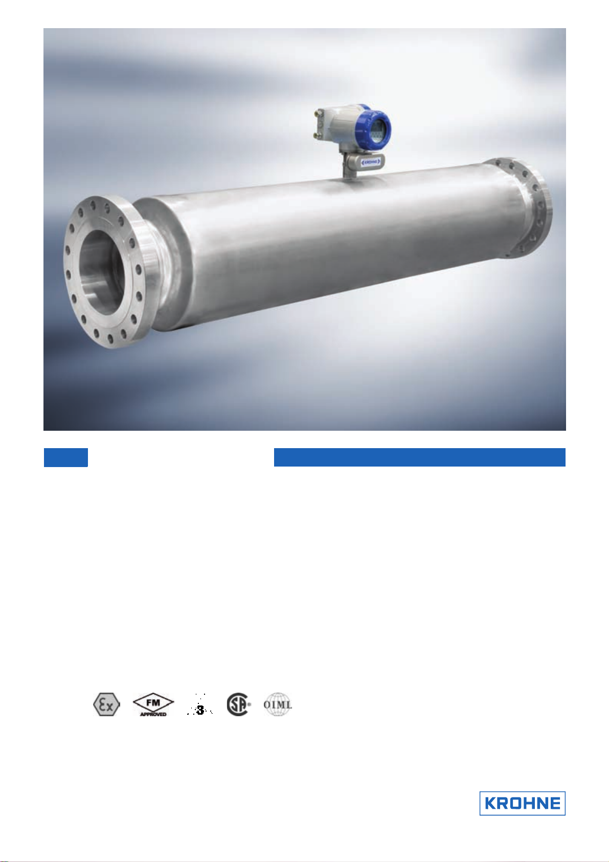
Sensor for bulk mass flow
• Large diameter for bulk measurement and custody transfer of liquids and gases
• Stainless Steel measuring tubes (NACE Compliant)
• Super Duplex option offering a maximum operating pressure of 180 barg
The documentation is only complete when used in combination with the relevant
documentation for the converter.
© KROHNE 10/2010 - 4000228104 - TD OPTIMASS 2000 R04 en
Page 2

CONTENTS
OPTIMASS 2000
1 Product features 3
1.1 The solution for bulk mass flow measurement............................................................... 3
1.2 Features and options........................................................................................................ 5
1.3 Meter / converter combinations....................................................................................... 6
1.4 Measuring principle (twin tube) ....................................................................................... 6
2 Technical data 8
2.1 Technical data................................................................................................................... 8
2.2 Measuring accuracy ....................................................................................................... 13
2.3 Guidelines for maximum operating pressure................................................................ 14
2.4 Dimensions and weights ................................................................................................ 16
2.4.1 Flanged versions................................................................................................................... 16
2.4.2 Hygienic versions .................................................................................................................. 21
2.4.3 Heating jacket version .......................................................................................................... 23
2.4.4 Purge port option .................................................................................................................. 24
3 Installation 25
3.1 Intended use ................................................................................................................... 25
3.2 Mounting restrictions ..................................................................................................... 25
3.2.1 General installation principles ............................................................................................. 25
3.2.2 Sunshades............................................................................................................................. 27
2
www.krohne.com 10/2010 - 4000228104 - TD OPTIMASS 2000 R04 en
Page 3
OPTIMASS 2000
1.1 The solution for bulk mass flow measurement
Whilst the OPTIMASS 2000 has been developed to meet the demanding custody transfer
requirements of the oil and gas industry, it is well suited to bulk measurement in many
applications. The option of Super Duplex (UNS S32750) provides a maximum operating pressure
of 180 barg.
A high level of performance makes the OPTIMASS 2000 suitable for the bulk measurement of
petroleum and oil as well as products like syrup, molasses and raw chemicals.
Combined with the power of the MFC 300, the OPTIMASS 2000 will provide accurate
measurement of volume, mass; density and concentration.
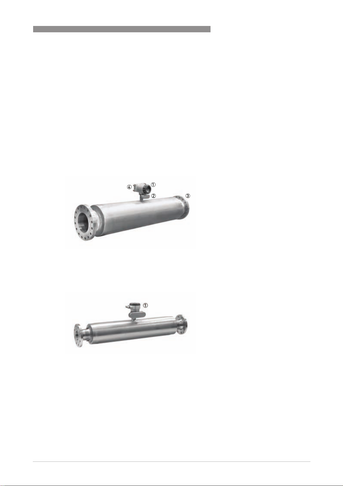
PRODUCT FEATURES 1
1 Comprehensive diagnostic capabilities.
2 Standard electronics for all sensors with redundant storage of calibration and sensor data.
3 Standard flange process connections available.
4 Modular electronics with a range of output options (see separate documentation for details).
1 Remote terminal box
www.krohne.com10/2010 - 4000228104 - TD OPTIMASS 2000 R04 en
3
Page 4

1 PRODUCT FEATURES
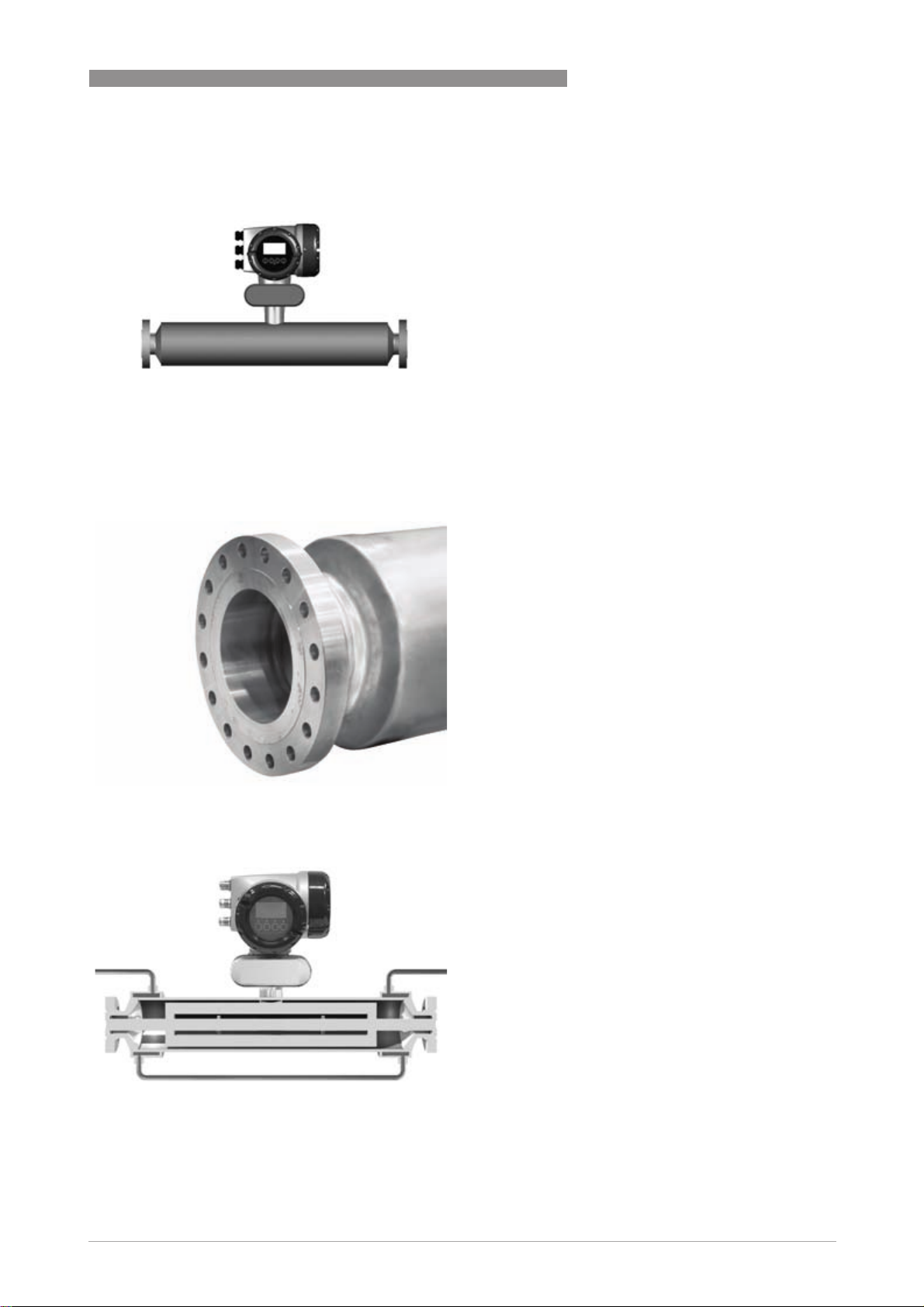
Highlights
• Innovative twin measuring tube design with large tube size, provide high flow rate capacity
• Easily drained and easy to clean
• Optional heating jacket
• High accuracy for custody transfer
• Optimised flow divider for minimum pressure loss
• Modular electronics concept: electronics and sensor are easy to replace
• Super Duplex option for operating pressures up to 180 barg
• Secondary containment up to 150 barg
Industries
• Oil & Gas
• Waste Water
• Chemical
• Paper & Pulp
• Food & Beverage
• Pharmaceutical
• Fresh Water
OPTIMASS 2000
Applications
• Bulk loading/unloading
• Custody transfer for volume and mass
• High Volume
• Pipeline measurement applications
4
www.krohne.com 10/2010 - 4000228104 - TD OPTIMASS 2000 R04 en
Page 5
OPTIMASS 2000
1.2 Features and options
Features
Connection options
PRODUCT FEATURES 1
• Flow rates up to 2,300,000 kg/h /
84,510 lbs/min.
• Integrated electronics.
• Self Draining.
• Best in class for zero stability.
• Standard flanges with ratings up to
1500 lbs / PN160.
• Supports a wide range of industry standard hygienic
connections.
• Hygienic connections (DN100 only) for bulk
measurement in the food/beverage industry.
Heating jacket and purge port
• Heating jacket option for use with temperature
dependant products.
• Prevents solidification of process product.
• Purge port option for protection in the event of
measuring tube faliure.
• Allows hazardous chemicals to be drained away
safely.
• Can also be used for the early detection of
measuring tube failure where highly toxic
chemicals are being measured.
www.krohne.com10/2010 - 4000228104 - TD OPTIMASS 2000 R04 en
5
Page 6
1 PRODUCT FEATURES
OPTIMASS 2000
1.3 Meter / converter combinations
Converter MFC 010 MFC 300
Configuration Compact Compact Remote field Remote wall Remote rack
OPTIMASS 2000 2010C 2300C 2300F 2300W 2300R
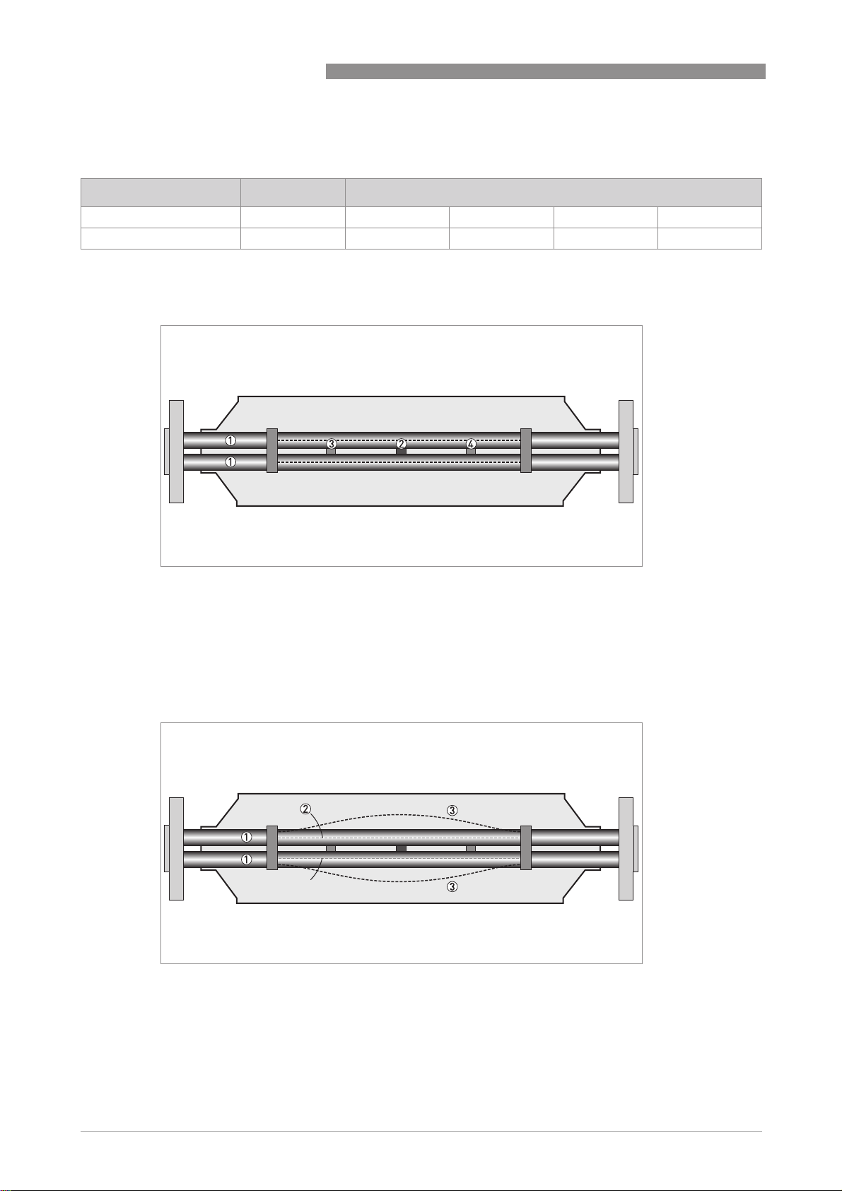
1.4 Measuring principle (twin tube)
Static meter not energised and with no flow
1 Measuring tubes
2 Drive coil
3 Sensor 1
4 Sensor 2
A Coriolis twin tube mass flowmeter consists of two measuring tubes 1 a drive coil 2 and two
sensors (3 and 4) that are positioned either side of the drive coil.
Energised meter
1 Measuring tubes
2 Direction of oscilation
3 Sine wave
When the meter is energised, the drive coil vibrates the measuring tubes causing them to
oscillate and produce a sine wave 3. The sine wave is monitored by the two sensors.
6
www.krohne.com 10/2010 - 4000228104 - TD OPTIMASS 2000 R04 en
Page 7
OPTIMASS 2000
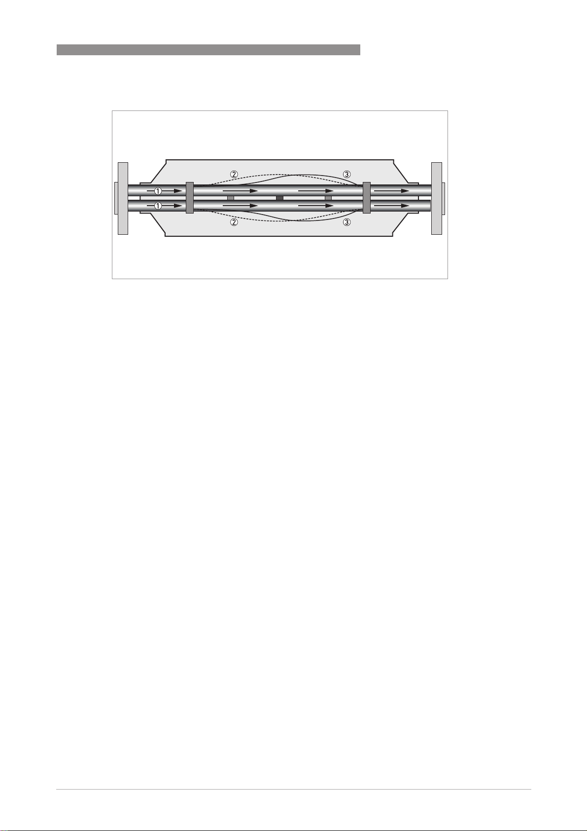
Energised meter with process flow
1 Process flow
2 Sine wave
3 Phase shift
When a fluid or gas passes through the tubes, the coriolis effect causes a phase shift in the sine
wave that is detected by the two sensors. This phase shift is directly proportional to the mass
flow.
Density measurement is made by evaluation of the frequency of vibration and temperature
measurement is made using a Pt500 sensor.
PRODUCT FEATURES 1
www.krohne.com10/2010 - 4000228104 - TD OPTIMASS 2000 R04 en
7
Page 8

2 TECHNICAL DATA
OPTIMASS 2000
2.1 Technical data
•
The following data is provided for general applications. If you require data that is more
relevant to your specific application, please contact us or your local representative.
•
Additional information (certificates, special tools, software,...) and complete product
documentation can be downloaded free of charge from the website (Download Center).
Measuring system
Measuring principle Coriolis mass flow
Application range Mass flow and density measurement of fluids, gases and solids
Measured values Mass, density, temperature
Calculated values Volume, referred density, concentration, velocity
Design
Basic System consists of a measuring sensor and a converter to process the
Features Fully welded maintenance free sensor with dual-straight measuring tube
Variants
Variants
VariantsVariants
Compact version Integral converter
Remote version Available with field, wall or 19" rack mount versions of the converter
Modbus version Sensor with integral electronics providing Modbus output for connection to a
output signal
PLC
Measuring accuracy
Mass
Mass
MassMass
Liquid ±0.1% of actual measured flow rate + zero stability
Gas ±0.5% of actual measured flow rate + zero stability
Repeatability Better than 0.05% plus zero stability (includes the combined effects of
Zero stability
Zero stability
Zero stabilityZero stability
S100 < 7 kg/h
S150 < 18 kg/h
S250 < 50 kg/h
Reference conditions
Reference conditions
Reference conditionsReference conditions
Product Water
Temperature +20°C / +68°F
Operating pressure 1 barg / 14.5 psig
Effect on sensor zero point caused by a shift in process temperature
Effect on sensor zero point caused by a shift in process temperature
Effect on sensor zero point caused by a shift in process temperatureEffect on sensor zero point caused by a shift in process temperature
Stainless Steel 0.0004% per 1°C / 0.000022% per 1°F
Effect on sensor zero point caused by a shift in process pressure
Effect on sensor zero point caused by a shift in process pressure
Effect on sensor zero point caused by a shift in process pressureEffect on sensor zero point caused by a shift in process pressure
Stainless Steel 0.0002% of the max flow rate per 1 bar
Density
Density
DensityDensity
Measuring range
Accuracy
repeatability, linearity and hysteresis)
per 1 psig
400...3000 kg/m3 / 25...187 lbs/ft
±2 kg/m3 / ±0.13 lbs/ft
3
3
. / 0.0000014% of the max flow rate
rel
8
www.krohne.com 10/2010 - 4000228104 - TD OPTIMASS 2000 R04 en
Page 9

OPTIMASS 2000
TECHNICAL DATA 2
On site calibration
Temperature
Temperature
TemperatureTemperature
Accuracy ±1°C / ±1.8°F
±0.5 kg/m3 / ±0.033 lbs/ft
3
Operating conditions
Maximum flow rates
Maximum flow rates
Maximum flow ratesMaximum flow rates
S100 420000 kg/h / 14698 lbs/min
S150 900000 kg/h / 33804 lbs/min
S250 2300000 kg/h / 84510 lbs/min
Custody transfer flow rates (mass)
Custody transfer flow rates (mass)
Custody transfer flow rates (mass)Custody transfer flow rates (mass)
S100 11000...220000 kg/h / 404...8083 lbs/min
S150 25000...500000 kg/h / 919...18371 lbs/min
S250 60000...1200000 kg/h / 2205...44092 lbs/min
Custody transfer flow rates (volume)
Custody transfer flow rates (volume)
Custody transfer flow rates (volume)Custody transfer flow rates (volume)
S100
S150
S250
Ambient temperature
Ambient temperature
Ambient temperatureAmbient temperature
Compact version with Aluminium
converter
Compact version with Stainless Steel
converter
Remote versions -40...+65°C / -40…+149°F
Process temperature
Process temperature
Process temperatureProcess temperature
Flanged connection -45…+130°C / -49…+266°F
Hygienic connection (S100 only)
Nominal pressure at 20
Nominal pressure at 20°C / 68
Nominal pressure at 20Nominal pressure at 20
Measuring tube (Duplex UNS S31803)
Measuring tube (Duplex UNS S31803)
Measuring tube (Duplex UNS S31803) Measuring tube (Duplex UNS S31803)
PED 97/23/EC -1…150 barg / -14.5…2175 psig
FM -1…140 barg / -14.5…2030 psig
CRN / ASME B31.3 -1…100 barg / -14.5…1450 psig
Measuring tube (Super Duplex UNS S32750)
Measuring tube (Super Duplex UNS S32750)
Measuring tube (Super Duplex UNS S32750) Measuring tube (Super Duplex UNS S32750)
PED 97/23/EC -1…180 barg / -14.5…2610 psig
FM -1…140 barg / -14.5…2030 psig
CRN / ASME B31.3 (pending) -1…130 barg / -14.5…1885 psig
Outer cylinder
Outer cylinder
Outer cylinderOuter cylinder
Non PED / CRN approved Typical burst pressure > 100 barg / 1450 psig
PED approved secondary containment -1...40 barg / -14.5...580 psig
Effect on sensor zero point caused by a shift in process temperature
Effect on sensor zero point caused by a shift in process temperature
Effect on sensor zero point caused by a shift in process temperatureEffect on sensor zero point caused by a shift in process temperature
Stainless Steel 0.0004% per 1°C / 0.000022% per 1°F
C / 68°F
C / 68C / 68
F
FF
11...220 m3/h / 1660...33210 bbl/day
25...500 m3/h / 3774...75478 bbl/day
60...1200 m3/h / 9057...181147 bbl/day
Assumes operating density 1000 kg/m3 / 62.4 lb/ft
-40...+60°C / -40…+140°F
Extended temperature range: 65°C / 149°F for some I/O options. For more
information contact manufacturer.
-40...+55°C / -40…+130°F
-1...150 barg / -14.5...2175 psig (Duplex option)
3
www.krohne.com10/2010 - 4000228104 - TD OPTIMASS 2000 R04 en
9
Page 10

2 TECHNICAL DATA
Effect on sensor zero point caused by a shift in process pressure
Effect on sensor zero point caused by a shift in process pressure
Effect on sensor zero point caused by a shift in process pressureEffect on sensor zero point caused by a shift in process pressure
Stainless Steel 0.0002% of the max flow rate per 1 bar
per 1 psig
Fluid properties
Fluid properties
Fluid propertiesFluid properties
Permissible physical condition Liquids, gases, slurries
Permissible gas content (volume) Contact manufacturer for information.
Permissible solid content (volume) Contact manufacturer for information.
Protection category (acc. to EN 60529) IP 67, NEMA 4X
Installation conditions
Inlet runs None required
Outlet runs None required
Materials
Measuring tube Stainless Steel UNS S31803 (1.4462)
Optional UNS S32750 (1.4410)
Spigot Stainless Steel UNS J92205 (1.4470)
Optional UNS J93404 (1.4469)
Flanges Stainless Steel AISI 316 / 316L (1.4401 / 1.4404) dual certified
Optional Stainless Steel UNS S31803 (1.4462) (NACE approved)
Optional UNS S32750 (1.4410) (NACE approved)
Outer cylinder Stainless Steel AISI 304 / 304L (1.4301 / 1.4307) dual certified
Optional Stainless Steel AISI 316 / 316L (1.4401 / 1.4404) dual certified
Optional Stainless Steel UNS S31803 (1.4462) 1
Heating jacket version
Heating jacket version
Heating jacket versionHeating jacket version
Heating jacket Stainless Steel 316L (1.4404)
Note: the outer cylinder is in contact with the heating medium
All versions
All versions
All versionsAll versions
Sensor electronics housing Stainless Steel 316L (1.4409)
Optional Stainless Steel 316 (1.4469)
Junction box (remote version) Die cast Aluminium (polyurethane coating)
. / 0.0000014% of the max flow rate
rel
OPTIMASS 2000
Process connections
Flange
Flange
FlangeFlange
DIN DN100…300 / PN16…160
ASME 4...12" / ASME 150…1500
JIS 100A / 10...20K
Hygienic
Hygienic
HygienicHygienic
Tri-clover 4"
Tri-clamp DIN 32676 DN100
Tri-clamp ISO 2852 4"
DIN 11864-2 Form A DN100
Male thread DIN 11851 DN100
Male thread SMS 4"
Male thread IDF / ISS 4"
Male thread RJT 4"
10
www.krohne.com 10/2010 - 4000228104 - TD OPTIMASS 2000 R04 en
Page 11

OPTIMASS 2000
TECHNICAL DATA 2
Electrical connections
Electrical connections For full details, including: power supply, power consumption etc., see
I/O For full details of I/O options, including data streams and protocols, see
technical data for the relevant converter.
technical data for the relevant converter.
Approvals
Mechanical
Mechanical
MechanicalMechanical
Electromagnetic compatibility (EMC)
acc. to CE
European Pressure Equipment Directive PED 97-23 EC (acc. to AD 2000 Regelwerk)
Factory Mutual / CSA Class I, Div 1 groups A, B, C, D
ANSI / CSA (Dual Seal) 12.27.901-2003
Hygienic 3A 28-03
Custody Transfer MID 2004/22/EC MI-005
ATEX (acc. 94/9/EC)
ATEX (acc. 94/9/EC)
ATEX (acc. 94/9/EC)ATEX (acc. 94/9/EC)
OPTIMASS 2300C non Ex i Signal outputs
OPTIMASS 2300C non Ex i Signal outputs
OPTIMASS 2300C non Ex i Signal outputsOPTIMASS 2300C non Ex i Signal outputs
Ex d connection compartment II 2 G Ex d [ib] IIC T6....T1
Ex e connection compartment II 2 G Ex de [ib] IIC T6....T1
OPTIMASS 2300C Ex i signal outputs
OPTIMASS 2300C Ex i signal outputs
OPTIMASS 2300C Ex i signal outputsOPTIMASS 2300C Ex i signal outputs
Ex d connection compartment II 2(1) G Ex d [ia/ib] IIC T6....T1
Ex e connection compartment II 2(1) G Ex de [ia/ib] IIC T6....T1
OPTIMASS 2000 / 2010C
OPTIMASS 2000 / 2010C II 2 G Ex ib IIC T6…T1
OPTIMASS 2000 / 2010COPTIMASS 2000 / 2010C
1 Where this option is ordered, the electronics stem material is UNS J92205 (1.4470)
Namur NE 21/5.95
2004/108/EC (EMC)
2006/95/EC (Low Voltage Directive)
Class II, Div 1 groups E, F, G
Class III, Div 1 hazardous areas
Class I, Div 2 groups A, B, C, D
Class II, Div 2 groups F, G
Class III, Div 2 hazardous areas
ASME BPE
II 2 D Ex tD A21 IP6x T160°C
II 2 D Ex tD A21 IP6x T160°C
II 2(1) D Ex tD [iaD] A21 IP6x T160°C
II 2(1) D Ex tD [iaD] A21 IP6x T160°C
II 2 D Ex ibD 21 T165 °C
www.krohne.com10/2010 - 4000228104 - TD OPTIMASS 2000 R04 en
11
Page 12

2 TECHNICAL DATA
ATEX (acc. 94/9/EC) temperature limits
OPTIMASS 2000
Ambient temp.
T
°C
amb
OPTIMASS 2000 / 2010C with or without
heating jacket / insulation
OPTIMASS 2300C Aluminium converter
housing - with or without heating jacket
/ insulation
OPTIMASS 2300C Stainless Steel
converter housing - with or without
heating jacket / insulation
1 depending on I/O option. Please call for more information.
40 65 T6 T80
65 75 T5 T95
40 50 T6 T80
50 65 T5 T95
60 60 T4-T1 T90
65 1 65 T4-T1 T95
40 50 T6 T80
50 65 T5 T95
55 55 T5-T1 T85
Max. medium
temp. T
75 T5 T95
110 T4 T130
130 T3-T1 T150
110 T4 T130
130 T3-T1 T150
65 T5 T95
100 T4 T130
130 T3-T1 T160
100 T4-T1 T130
65 T5 T95
100 T4 T130
120 T3-T1 T150
75 T4-T1 T105
°C
m
Temp. class Max. surface
temp. °C
Maximum end loadings
S100 S150 S250
Flanges
Flanges
FlangesFlanges
20°C 40 barg 150kN 350kN 550kN
100 barg 100kN 120kN 60kN
150 barg
180 barg
130°C 32 barg 150kN 280kN 400kN
80 barg 60kN 50kN 50kN
115 barg
130 barg
Hygienic (all connections)
Hygienic (all connections)
Hygienic (all connections)Hygienic (all connections)
130°C 10 barg 5kN - -
12
www.krohne.com 10/2010 - 4000228104 - TD OPTIMASS 2000 R04 en
Page 13

OPTIMASS 2000
2.2 Measuring accuracy
1.6
1.4
1.2
1.0
0.8
0.6
0.4
0.2
0
TECHNICAL DATA 2
X flow rate [%]
Y measuring error [%]
Measuring error
The measuring error is obtained from the combined effects of accuracy and zero stability.
Reference conditions
Product Water
Temperature +20°C / +68°F
Operating pressure 1 barg / 14.5 psig
www.krohne.com10/2010 - 4000228104 - TD OPTIMASS 2000 R04 en
13
Page 14

2 TECHNICAL DATA
2.3 Guidelines for maximum operating pressure
Notes:
• Ensure that the meter is used within its operating limits
• All hygienic process connections have a maximum operating rating of 10 barg
at 130°C / 145 psig at 266°F
Pressure / temperature de-rating, all meter sizes in metric (flanged connections as
Pressure / temperature de-rating, all meter sizes in metric (flanged connections as
Pressure / temperature de-rating, all meter sizes in metric (flanged connections as Pressure / temperature de-rating, all meter sizes in metric (flanged connections as
per EN 1092-1:2007)
per EN 1092-1:2007)
per EN 1092-1:2007)per EN 1092-1:2007)
OPTIMASS 2000
X temperature [°C]
Y pressure [barg]
1 Measuring tube (UNS S32750) PED certification
2 Measuring tube (UNS S31803) PED certification
3 Measuring tube (UNS S31803 / S32750) FM certification
4 Measuring tube (UNS S31803) CRN certification
Linear de-rating of PED certified secondary containment
Outer cylinder material -45°C 20°C 130°C
304 / L or 316 / L 40 barg 40 barg 32 barg
UNS S31803 150 barg 150 barg 100 barg
14
www.krohne.com 10/2010 - 4000228104 - TD OPTIMASS 2000 R04 en
Page 15

OPTIMASS 2000
Pressure / temperature de-rating, all meter sizes, in imperial (flanged connections as
Pressure / temperature de-rating, all meter sizes, in imperial (flanged connections as
Pressure / temperature de-rating, all meter sizes, in imperial (flanged connections as Pressure / temperature de-rating, all meter sizes, in imperial (flanged connections as
per ASME B16.5)
per ASME B16.5)
per ASME B16.5)per ASME B16.5)
TECHNICAL DATA 2
X temperature [°F]
Y pressure [psig]
1 Measuring tube (UNS S32750) PED certification
2 Measuring tube (UNS S31803) PED certification
3 Measuring tube (UNS S31803 / S32750) FM certification
4 Measuring tube (UNS S31803) CRN certification
Linear de-rating of PED certified secondary containment
Outer cylinder material -49°F 68°F 266°F
304 / L or 316 / L 580 psig 580 psig 464 psig
UNS S31803 2175 psig 2175 psig 1450 barg
Flanges
• DIN flange ratings are based on EN 1092-1 2007 table G.4.1 material group 14EO
• ASME flange ratings are based on ASME B16.5 2003 table 2 material group 2.2
• JIS flange ratings are based on JIS 2220: 2001 table 1 division 1 material group 022a
Notes
• The maximum operating pressure will be either the flange rating or the measuring tube
rating, WHICHEVER IS THE LOWER!
• The manufacturer recommends that the seals are replaced at regular intervals. This will
maintain the hygienic integrity of the connection.
WHICHEVER IS THE LOWER!
WHICHEVER IS THE LOWER!WHICHEVER IS THE LOWER!
www.krohne.com10/2010 - 4000228104 - TD OPTIMASS 2000 R04 en
15
Page 16

2 TECHNICAL DATA
2.4 Dimensions and weights
2.4.1 Flanged versions
1
C1
D
A
OPTIMASS 2000
E
H
2
C2
1 Compact version
2 Remote version
D
B
E
A
B
FG
C2
H
Meter weights (PN40 flanges).
Weight [kg]
S100 S150 S250
Aluminium (compact) 84.8 211.5 444.5
Stainless Steel (compact) 90.1 216.8 449.8
Aluminium (remote) 80.8 207.5 440.5
Stainless Steel (remote) 81.7 208.4 441.4
Weight [lbs]
S100 S150 S250
Aluminium (compact) 187 466 980
Stainless Steel (compact) 198 478 991
Aluminium (remote) 178 457 971
Stainless Steel (remote) 180 459 973
For meter weights with different flange ratings, please contact the manufacturer.
16
www.krohne.com 10/2010 - 4000228104 - TD OPTIMASS 2000 R04 en
Page 17

OPTIMASS 2000
TECHNICAL DATA 2
Measuring tube in Stainless Steel
Dimensions [mm]
S100 S150 S250
A 219 ±5 323 ±5 406 ±5
C1 (compact) 370 ±5 422 ±5 463 ±5
C2 (remote) 293 ±5 345 ±5 386 ±5
D 160
E 60
F 123.5
G 137
H 98.5
Dimensions [inches]
S100 S150 S250
A 8.6 ±0.2 12.7 ±0.2 16 ±0.2
C1 (compact) 14.6 ±0.2 16.6 ±0.2 18.2 ±0.2
C2 (remote) 11.5 ±0.2 13.6 ±0.2 15.2 ±0.2
D 6.3
E 2.4
F 4.9
G 5.4
H 3.9
Flange connections
Dimension B [mm]
S100 S150 S250
PN16
PN16
PN16PN16
DN100 1284 - -
DN150 1284 1581 -
DN200 - 1581 -
DN250 - - 1960
DN300 - - 1960
PN40
PN40
PN40PN40
DN100 1310 - -
DN150 1330 1621 -
DN200 - 1647 -
DN250 - - 2030
DN300 - - 2050
PN63
PN63
PN63PN63
DN100 1336 - -
DN150 1370 1661 -
DN200 - 1691 -
www.krohne.com10/2010 - 4000228104 - TD OPTIMASS 2000 R04 en
17
Page 18

2 TECHNICAL DATA
Dimension B [mm]
S100 S150 S250
DN250 - - 2070
DN300 - - 2100
PN100
PN100
PN100PN100
DN100 1360 - -
DN150 1410 1701 -
DN200 - 1731 -
DN250 - - 1977
DN300 - - 2160
PN160
PN160
PN160PN160
DN100 1380 - -
DN150 1436 1727 -
DN200 - 1751 -
DN250 2130
DN300 - - 2170
ASME 150
ASME 150
ASME 150ASME 150
4" 1334 - -
6" 1358 1649 -
8" - 1675 -
10" - - 2024
12" - - 2050
ASME 300
ASME 300
ASME 300ASME 300
4" 1352 - -
6" 1378 1669 -
8" - 1695 -
10" - - 2056
12" - - 2082
ASME 600
ASME 600
ASME 600ASME 600
4" 1398 - -
6" 1428 1719 -
8" - 1751 -
10" - - 2138
12" - - 2146
ASME 900
ASME 900
ASME 900ASME 900
4" 1422 - -
6" 1474 1765 -
8" - 1809 -
10" - - 2202
12" - - 2234
ASME 1500
ASME 1500
ASME 1500ASME 1500
4" 1442 - -
6" 1554 - -
OPTIMASS 2000
18
www.krohne.com 10/2010 - 4000228104 - TD OPTIMASS 2000 R04 en
Page 19

OPTIMASS 2000
TECHNICAL DATA 2
Dimension B [mm]
S100 S150 S250
8" - 1911 -
10" - - 2400
12" - - 2400
JIS 10K
JIS 10K
JIS 10KJIS 10K
100A 1332 - -
JIS 20K
JIS 20K
JIS 20KJIS 20K
100A 1332 - -
Dimension B [inches]
S100 S150 S250
PN16
PN16
PN16PN16
DN100 50.5 - -
DN150 50.5 62.2 -
DN200 - 62.2 -
DN250 - - 77.2
DN300 - - 77.2
PN40
PN40
PN40PN40
DN100 51.5 - -
DN150 52.6 64 -
DN200 - 65.5 -
DN250 - - 80.7
DN300 - - 82.3
PN63
PN63
PN63PN63
DN100 53.2 - -
DN150 52.3 67 -
DN200 - 65 -
DN250 - - 84.8
DN300 - - 81.5
PN100
PN100
PN100PN100
DN100 53.9 - -
DN150 55.5 66.6 -
DN200 - 68.3 -
DN250 - - 83.5
DN300 - - 85.9
PN160
PN160
PN160PN160
DN100 54.3
DN150 56.5 68 -
DN200 68.9 -
DN250 83.9
DN300 - - 85.4
www.krohne.com10/2010 - 4000228104 - TD OPTIMASS 2000 R04 en
19
Page 20

2 TECHNICAL DATA
Dimension B [inches]
S100 S150 S250
ASME 150
ASME 150
ASME 150ASME 150
4" 52.5 - -
6" 53.4 65 -
8" - 66 -
10" - - 80.4
12" - - 81.5
ASME 300
ASME 300
ASME 300ASME 300
4" 53.2 - -
6" 54.2 65.8 -
8" - 66.8 -
10" - - 81.7
12" - - 82.7
ASME 600
ASME 600
ASME 600ASME 600
4" 54.9 - -
6" 56.1 67.8 -
8" - 68.9 -
10" - - 85
12" - - 85.2
ASME 900
ASME 900
ASME 900ASME 900
4" 55.2 - -
6" 57.9 69.5 -
8" - 71.2 -
10" - - 87.5
12" - - 88.7
ASME 1500
ASME 1500
ASME 1500ASME 1500
4" 56.8 - -
6" 61.2 - -
8" - 75.3 -
10" - - 94.5
12" - - 94.5
JIS 10K
JIS 10K
JIS 10KJIS 10K
100A 52.5 - -
JIS 20K
JIS 20K
JIS 20KJIS 20K
100A 52.5 - -
OPTIMASS 2000
20
www.krohne.com 10/2010 - 4000228104 - TD OPTIMASS 2000 R04 en
Page 21

OPTIMASS 2000
2.4.2 Hygienic versions
Hygienic connections: all welded versions
S100 S150 S250
TECHNICAL DATA 2
Dimension B [mm]
Tri-clover
Tri-clover
Tri-cloverTri-clover
4" 1223 - -
Tri-clamp DIN 32676
Tri-clamp DIN 32676
Tri-clamp DIN 32676Tri-clamp DIN 32676
DN100 1236 - -
Tri-clamp ISO 2852
Tri-clamp ISO 2852
Tri-clamp ISO 2852Tri-clamp ISO 2852
4" 1223 - -
DIN 11864-2 form A
DIN 11864-2 form A
DIN 11864-2 form ADIN 11864-2 form A
DN100 1296 - -
Dimension B [inches]
S100 S150 S250
Tri-clover
Tri-clover
Tri-cloverTri-clover
4" 48 - -
Tri-clamp DIN 32676
Tri-clamp DIN 32676
Tri-clamp DIN 32676Tri-clamp DIN 32676
DN100 48.7 - -
Tri-clamp ISO 2852
Tri-clamp ISO 2852
Tri-clamp ISO 2852Tri-clamp ISO 2852
4" 48 - -
DIN 11864-2 form A
DIN 11864-2 form A
DIN 11864-2 form ADIN 11864-2 form A
DN100 51 - -
www.krohne.com10/2010 - 4000228104 - TD OPTIMASS 2000 R04 en
21
Page 22

2 TECHNICAL DATA
OPTIMASS 2000
Hygienic connections: adapter versions (male thread)
Dimension B [mm]
S100 S150 S250
Male thread DIN 11851
Male thread DIN 11851
Male thread DIN 11851Male thread DIN 11851
DN100 1288 - -
Male thread SMS
Male thread SMS
Male thread SMSMale thread SMS
4" 1236 - -
Male thread IDF/ISS
Male thread IDF/ISS
Male thread IDF/ISSMale thread IDF/ISS
4" 1223 - -
Male thread RJT
Male thread RJT
Male thread RJTMale thread RJT
4" 1234 - -
Dimension B [inches]
S100 S150 S250
Male thread DIN 11851
Male thread DIN 11851
Male thread DIN 11851Male thread DIN 11851
DN100 50.1 - -
Male thread SMS
Male thread SMS
Male thread SMSMale thread SMS
4" 48.7 - -
Male thread IDF/ISS
Male thread IDF/ISS
Male thread IDF/ISSMale thread IDF/ISS
4" 48 - -
Male thread RJT
Male thread RJT
Male thread RJTMale thread RJT
4" 48.6 - -
22
www.krohne.com 10/2010 - 4000228104 - TD OPTIMASS 2000 R04 en
Page 23

OPTIMASS 2000
2.4.3 Heating jacket version
Dimensions [mm]
S100 S150 S250
Heating connection size 25 mm (ERMETO)
TECHNICAL DATA 2
A 254 ±2.5 355 ±2.5 444 ±2.5
B 178 ±2.0 228 ±2.0 208 ±2.0
C 28 ±2.0 28 ±2.0 6.5 ±2.0
Dimensions [inches]
S100 S150 S250
Heating connection size 1" (NPTF)
A 10 ±0.1 14 ±0.1 17.5 ±0.06
B 7 ±0.08 9 ±0.08 8.2 ±0.08
C 1.1 ±0.08 1.1 ±0.08 0.25 ±0.08
www.krohne.com10/2010 - 4000228104 - TD OPTIMASS 2000 R04 en
23
Page 24

2 TECHNICAL DATA
2.4.4 Purge port option
Dimensions [mm]
S100 S150 S250
A 70 ±1.0 100 ±1.0
B 70 ±1.0 100 ±1.0
OPTIMASS 2000
Dimensions [inches]
S100 S150 S250
A 2.75 ±0.04 4.0 ±0.04
B 2.75 ±0.04 4.0 ±0.04
24
www.krohne.com 10/2010 - 4000228104 - TD OPTIMASS 2000 R04 en
Page 25

OPTIMASS 2000
3.1 Intended use
This mass flowmeter is designed for the direct measurement of mass flow rate, product density
and product temperature. Indirectly, it also enables the measurement of parameters like total
mass, concentration of dissolved substances and the volume flow. For use in hazardous areas,
special codes and regulations are also applicable and these are specified in a separate
documentation.
3.2 Mounting restrictions
3.2.1 General installation principles
There are no special installation requirements but you should note the following
points:
• Support the weight of the meter.
• The meter can be supported on the sensor body.
• On larger meter sizes and hygienic connections, it is strongly recommended that the meter is
not supported solely by the process pipework.
• No straight runs are required.
• The use of reducers and other fittings at flanges, including flexible hoses, is allowed but you
should take care to avoid cavitation.
• Avoid extreme pipe size reductions.
• Meters are not affected by crosstalk and can be mounted in series or in parallel.
• Avoid mounting the meter at the highest point in the pipeline where air / gas can collect.
INSTALLATION 3
www.krohne.com10/2010 - 4000228104 - TD OPTIMASS 2000 R04 en
25
Page 26

3 INSTALLATION
Mounting positions
OPTIMASS 2000
26
1 The meter can be mounted at an angle but it is recommended that the flow is uphill.
2 Avoid mounting the meter with the flow running downhill because it can cause siphoning. If the meter has to be mount-
ed with the flow running downhill, install an orifice plate or control valve downstream of the meter to maintain backpressure.
3 Horizontal mounting with flow running left to right.
4 Avoid mounting meter with long vertical runs after the meter as it can cause cavitation. Where the installation includes
a vertical run after the meter, install an orifice plate or control valve downstream to maintain backpressure.
5 The meter can be mounted vertically but it is recommended that the flow is uphill.
6 Avoid mounting the meter vertically with the flow running downhill. This can cause siphoning. If the meter has to be
installed this way, install an orifice plate or control valve downstream to maintain backpressure.
www.krohne.com 10/2010 - 4000228104 - TD OPTIMASS 2000 R04 en
Page 27

OPTIMASS 2000
Zero calibration
INSTALLATION 3
1 Where the meter has been installed vertically, install shut-off valves either side of the meter to assist with zero cali-
bration.
2 If the process flow cannot be stopped, install a bypass section for zero calibration.
3.2.2 Sunshades
The meter MUST be protected from strong sunlight.
1 Horizontal installation
2 Vertical installation
www.krohne.com10/2010 - 4000228104 - TD OPTIMASS 2000 R04 en
27
Page 28

K
K
K
KROHNE product overview
• Electromagnetic flowmeters
• Variable area flowmeters
• Ultrasonic flowmeters
• Mass flowmeters
• Vortex flowmeters
• Flow controllers
• Level meters
• Temperature meters
• Pressure meters
• Analysis products
• Measuring systems for the oil and gas industry
• Measuring systems for sea-going tankers
© KROHNE 10/2010 - 4000228104 - TD OPTIMASS 2000 R04 en - Subject to change without notice.
Head Office KROHNE Messtechnik GmbH
Ludwig-Krohne-Str. 5
D-47058 Duisburg (Germany)
Tel.:+49 (0)203 301 0
Fax:+49 (0)203 301 10389
info@krohne.de
The current list of all KROHNE contacts and addresses can be found at:
www.krohne.com
 Loading...