

Page 1
Technical Datasheet
Technical Datasheet
OPTIMASS 1000
OPTIMASS 1000
OPTIMASS 1000OPTIMASS 1000
Technical DatasheetTechnical Datasheet
Sensor for mass flow
• First choice for universal applications
• Best price-performance ratio
• A wide range of options available with no restrictions
The documentation is only complete when used in combination with the relevant
documentation for the signal converter.
© KROHNE 03/2011 - 4000040304 - TD OPTIMASS 1000 R05 en
Page 2

CONTENTS
OPTIMASS 1000
1 Product features 3
1.1 Overview............................................................................................................................ 3
1.2 Features and options........................................................................................................ 5
1.3 Meter / converter combinations....................................................................................... 6
1.4 Measuring principle (twin tube) ....................................................................................... 6
2 Technical data 8
2.1 Technical data................................................................................................................... 8
2.2 Measuring accuracy ....................................................................................................... 14
2.3 Guidelines for maximum operating pressure................................................................ 15
2.4 Dimensions and weights ................................................................................................ 17
2.4.1 Flanged versions................................................................................................................... 17
2.4.2 Hygienic versions .................................................................................................................. 21
2.4.3 Heating jacket version .......................................................................................................... 25
2.4.4 Purge port option .................................................................................................................. 26
3 Installation 27
3.1 Intended use ................................................................................................................... 27
3.2 Mounting restrictions ..................................................................................................... 27
3.2.1 General installation principles ............................................................................................. 27
3.2.2 Sunshades............................................................................................................................. 29
3.2.3 Maximum pipework forces (end loadings) ........................................................................... 30
2
www.krohne.com 03/2011 - 4000040304 - TD OPTIMASS 1000 R05 en
Page 3
OPTIMASS 1000
1.1 Overview
The OPTIMASS 1000 is the cost effective solution for accurate measurement for a variety of
applications. The OPTIMASS 1000 reliably measures massflow, density, volume, temperature,
volume concentration or solid content.
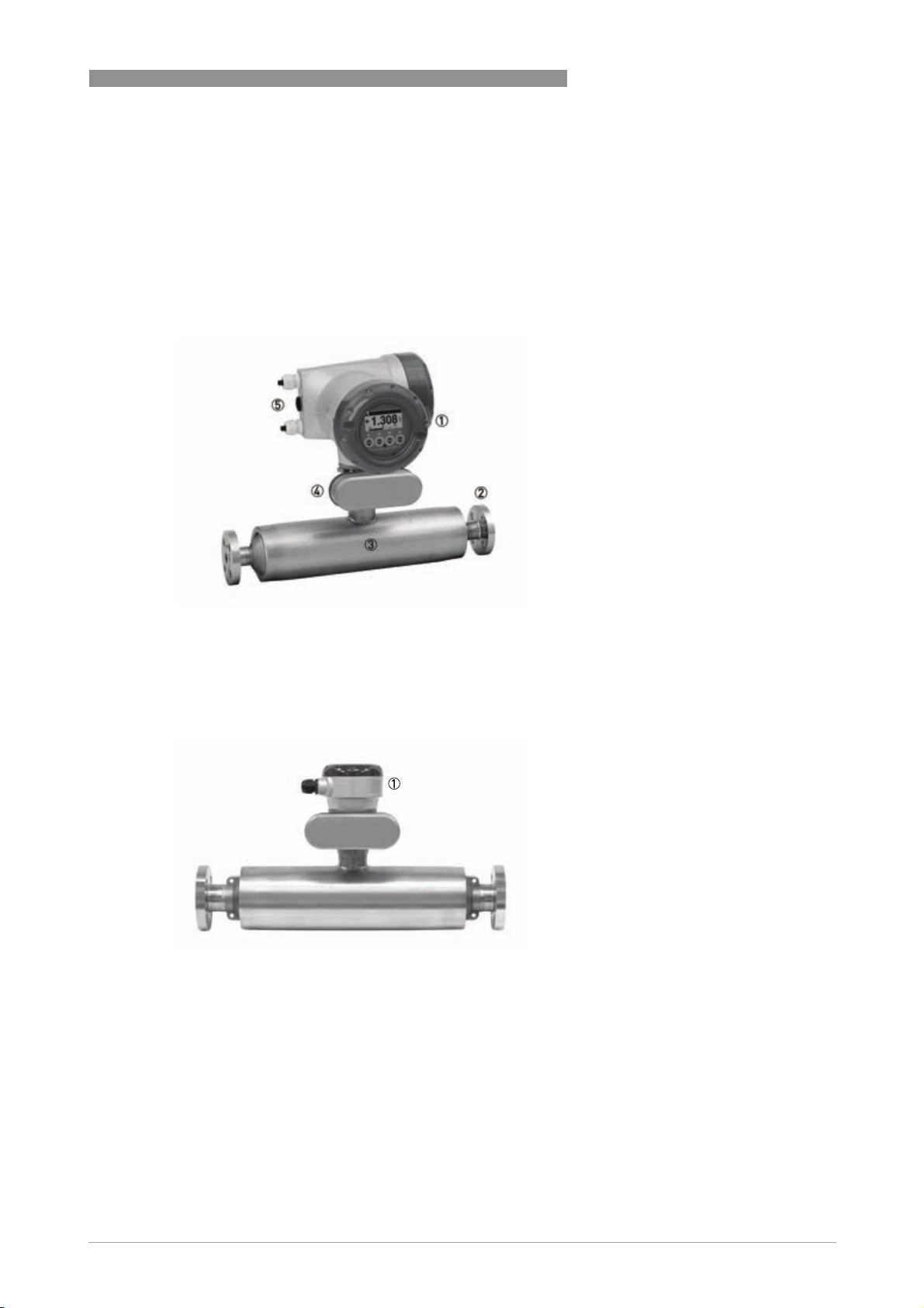
PRODUCT FEATURES 1
1 Comprehensive diagnostic capabilities.
2 Standard flange and hygienic process connections available.
3 Twin straight measuring tubes plus secondary containment available.
4 Standard electronics for all sensors with redundant storage of calibration and sensor data.
5 Modular electronics with a range of output options (see separate documentation for details).
1 Remote terminal box
www.krohne.com03/2011 - 4000040304 - TD OPTIMASS 1000 R05 en
3
Page 4

1 PRODUCT FEATURES
Highlights
• Innovative twin measuring tubes
• Easily drained and easy to clean
• Resistant to installation and process effects
• Long working life.
• Optimised flow divider for minimum pressure loss.
• High levels of accuracy means an excellent price / performance ratio.
• Modular electronics with data redundancy - "plug & play" replacement of electronics
Industries
• Water & wastewater
• Chemical
• Food & beverage
• Paper & pulp
• Petrochemical industry
• Pharmaceutical industry
OPTIMASS 1000
Applications
• Suitable for all standard applications up to 130°C
• Hygienic connections make it ideal for food / beverage applications.
4
www.krohne.com 03/2011 - 4000040304 - TD OPTIMASS 1000 R05 en
Page 5
OPTIMASS 1000
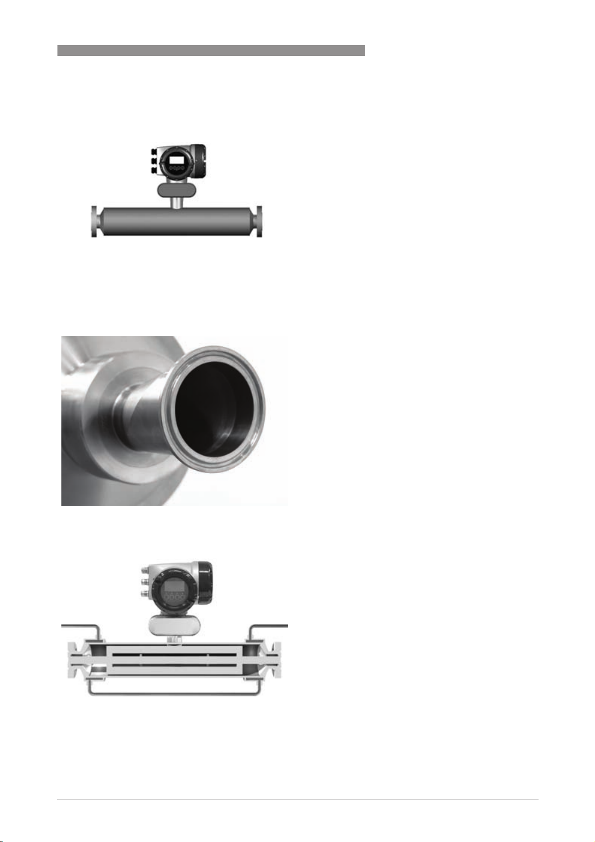
1.2 Features and options
Features
Connection options
PRODUCT FEATURES 1
• Available as compact or remote.
• Low pressure loss, guarantees a low pressure
drop across the meter.
• Self Draining.
• Easy to clean.
• A range of flanges up to ASME 600 / PN100.
• Supports a wide range of industry standard
hygienic connections.
• Adaptable to suit customer's hygienic
connections.
Heating jacket & purge port
• Heating jacket option for use with temperature
dependant products.
• Prevents solidification of process product.
• Purge port option for protection in the event of
measuring tube faliure.
• Allows hazardous chemicals to be drained away
safely.
• Can also be used for the early detection of
measuring tube failure where highly toxic
chemicals are being measured.
www.krohne.com03/2011 - 4000040304 - TD OPTIMASS 1000 R05 en
5
Page 6
1 PRODUCT FEATURES
OPTIMASS 1000
1.3 Meter / converter combinations
Converter MFC 010 MFC 300
Configuration Compact Compact Remote field Remote wall Remote rack
OPTIMASS 1000 1010C 1300C 1300F 1300W 1300R
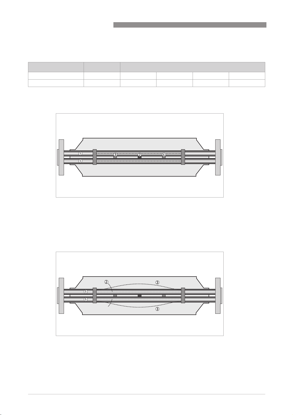
1.4 Measuring principle (twin tube)
Static meter not energised and with no flow
1 Measuring tubes
2 Drive coil
3 Sensor 1
4 Sensor 2
A Coriolis twin tube mass flowmeter consists of two measuring tubes 1 a drive coil 2 and two
sensors (3 and 4) that are positioned either side of the drive coil.
Energised meter
1 Measuring tubes
2 Direction of oscilation
3 Sine wave
When the meter is energised, the drive coil vibrates the measuring tubes causing them to
oscillate and produce a sine wave 3. The sine wave is monitored by the two sensors.
6
www.krohne.com 03/2011 - 4000040304 - TD OPTIMASS 1000 R05 en
Page 7
OPTIMASS 1000
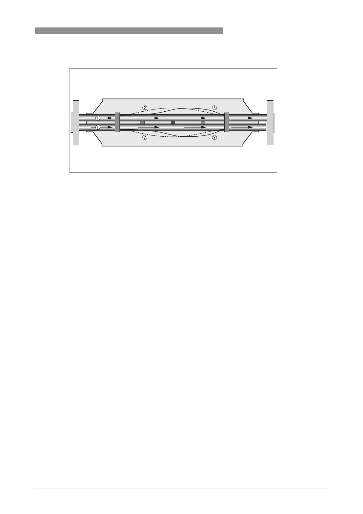
Energised meter with process flow
1 Process flow
2 Sine wave
3 Phase shift
When a fluid or gas passes through the tubes, the coriolis effect causes a phase shift in the sine
wave that is detected by the two sensors. This phase shift is directly proportional to the mass
flow.
Density measurement is made by evaluation of the frequency of vibration and temperature
measurement is made using a Pt500 sensor.
PRODUCT FEATURES 1
www.krohne.com03/2011 - 4000040304 - TD OPTIMASS 1000 R05 en
7
Page 8

2 TECHNICAL DATA
OPTIMASS 1000
2.1 Technical data
•
The following data is provided for general applications. If you require data that is more
relevant to your specific application, please contact us or your local representative.
•
Additional information (certificates, special tools, software,...) and complete product
documentation can be downloaded free of charge from the website (Download Center).
Measuring system
Measuring principle Coriolis mass flow
Application range Mass flow and density measurement of fluids, gases and solids
Measured values Mass, density, temperature
Calculated values Volume, referred density, concentration, velocity
Design
Basic System consists of a measuring sensor and a converter to process the
Features Fully welded maintenance free sensor with twin straight measuring tubes
Variants
Variants
VariantsVariants
Compact version Integral converter
Remote version Available with field, wall or 19" rack mount versions of the converter
Modbus version Sensor with integral electronics providing Modbus output for connection to a
output signal
PLC
Measuring accuracy
Mass
Mass
MassMass
Liquid ±0.15% of actual measured flow rate + zero stability
Gas ±0.5% of actual measured flow rate + zero stability
Repeatability Better than 0.05% plus zero stability (includes the combined effects of
Zero stability
Zero stability
Zero stabilityZero stability
Stainless Steel ±0.01% of maximum flow rate with respective sensor size
Reference conditions
Reference conditions
Reference conditionsReference conditions
Product Water
Temperature 20°C / 68°F
Operating pressure 1 barg / 14.5 psig
Effect on sensor zero point caused by a shift in process temperature
Effect on sensor zero point caused by a shift in process temperature
Effect on sensor zero point caused by a shift in process temperatureEffect on sensor zero point caused by a shift in process temperature
Stainless Steel 0.001% per 1°C / 0.00055% per 1°F
Effect on sensor zero point caused by a shift in process pressure
Effect on sensor zero point caused by a shift in process pressure
Effect on sensor zero point caused by a shift in process pressureEffect on sensor zero point caused by a shift in process pressure
Stainless Steel 0.00012% of the max flow rate per 1 bar
Density
Density
DensityDensity
Measuring range
Accuracy
On site calibration
repeatability, linearity and hysteresis)
. / 0.0000083% of the max flow rate
per 1 psig
400...2500 kg/m3 / 25...155 lbs/ft
±2 kg/m3 / ±0.13 lbs/ft3 (S15: ±5 kg/m3 / ±0.33 lbs/ft
±0.5 kg/m3 / ±0.033 lbs/ft
3
rel
3
3
)
8
www.krohne.com 03/2011 - 4000040304 - TD OPTIMASS 1000 R05 en
Page 9

OPTIMASS 1000
Temperature
Temperature
TemperatureTemperature
Accuracy ±1°C / 1.8°F
TECHNICAL DATA 2
Operating conditions
Maximum flow rates
Maximum flow rates
Maximum flow ratesMaximum flow rates
S15 6500 kg/h / 240 lbs/min
S25 27000 kg/h / 990 lbs/min
S40 80000 kg/h / 2935 lbs/min
S50 170000 kg/h / 6235 lbs/min
Ambient temperature
Ambient temperature
Ambient temperatureAmbient temperature
Compact version with Aluminium
converter
Compact version with Stainless Steel
converter
Remote versions -40...+65°C / -40…+149°F
Process temperature
Process temperature
Process temperatureProcess temperature
Flanged connection -40…+130°C / -40…+266°F
Hygienic connection -40…+130°C / -40…+266°F
Nominal pressure at 20
Nominal pressure at 20°C / 68
Nominal pressure at 20Nominal pressure at 20
Measuring tube
Measuring tube
Measuring tubeMeasuring tube
Stainless Steel -1…100 barg / -14.5…1450 psig
Outer cylinder
Outer cylinder
Outer cylinderOuter cylinder
Non PED / CRN approved Typical burst pressure > 100 barg / 1450 psig at 20°C
PED / CRN approved secondary
containment
PED approved secondary containment -1…100 barg / -14.5…1450 psig
Fluid properties
Fluid properties
Fluid propertiesFluid properties
Permissible physical condition Liquids, gases, slurries
Permissible gas content (volume) Contact manufacturer for information
Permissible solid content (volume) Contact manufacturer for information
Protection category (acc. to EN 60529) IP 67, NEMA 4X
C / 68°F
C / 68C / 68
F
FF
-40...+60°C / -40…+140°F
Extended temperature range: +65°C / +149°F for some I/O options. For more
information contact manufacturer.
-40...+55°C / -40…+130°F
-1…63 barg / -14.5…910 psig
Installation conditions
Inlet runs None required
Outlet runs None required
Materials
Measuring tube Stainless Steel UNS S31803 (1.4462)
Spigot Stainless Steel 316 / 316L (CF3M / 1.4409) dual certified
Flanges Stainless Steel 316 / 316L (1.4401 / 1.4404) dual certified
Outer cylinder Stainless Steel 304 / 304L (1.4301 / 1.4307) dual certified
Optional Stainless Steel 316 / 316L (1.4401 / 1.4404) dual certified
Heating jacket version
Heating jacket version
Heating jacket versionHeating jacket version
Heating jacket Stainless Steel 316L (1.4404)
The outer cylinder is in contact with the heating medium
www.krohne.com03/2011 - 4000040304 - TD OPTIMASS 1000 R05 en
9
Page 10

2 TECHNICAL DATA
All versions
All versions
All versionsAll versions
Sensor electronics housing Stainless Steel 316L (1.4409)
Junction box (remote version) Die cast Aluminium (polyurethane coating)
Optional Stainless Steel 316 (1.4401)
Process connections
Flange
Flange
FlangeFlange
DIN DN15…80 / PN40…100
ASME ½…3" / ASME 150…600
JIS 15…80A / 10...20K
Hygienic
Hygienic
HygienicHygienic
Tri-clover 1…3"
Tri-clamp DIN 32676 DN25…80
Tri-clamp ISO 2852 1…3"
DIN 11864-2 Form A DN25…80
Male thread DIN 11851 DN25...80
Male thread SMS 1...3"
Male thread IDF / ISS 1...3"
Male thread RJT 1...3"
OPTIMASS 1000
Electrical connections
Electrical connections For full details, including: power supply, power consumption etc., see
I/O For full details of I/O options, including data streams and protocols, see
technical data for the relevant converter
technical data for the relevant converter
Approvals and certifications
Mechanical
Mechanical
MechanicalMechanical
Electromagnetic compatibility (EMC)
acc. to CE
European Pressure Equipment Directive PED 97-23 EC (acc. to AD 2000 Regelwerk)
Factory Mutual / CSA Class I, Div 1 groups A, B, C, D
ANSI / CSA (Dual Seal) 12.27.901-2003
Hygienic 3A 28-03
Namur NE 21/5.95
89/336/EEC (EMC)
72/73/EEC (Low Voltage Directive)
Class II, Div 1 groups E, F, G
Class III, Div 1 hazardous areas
Class I, Div 2 groups A, B, C, D
Class II, Div 2 groups F, G
Class III, Div 2 hazardous areas
10
www.krohne.com 03/2011 - 4000040304 - TD OPTIMASS 1000 R05 en
Page 11

OPTIMASS 1000
ATEX (acc. 94/9/EC)
ATEX (acc. 94/9/EC)
ATEX (acc. 94/9/EC)ATEX (acc. 94/9/EC)
OPTIMASS 1300C non Ex i Signal outputs without heating jacket / insulation
OPTIMASS 1300C non Ex i Signal outputs without heating jacket / insulation
OPTIMASS 1300C non Ex i Signal outputs without heating jacket / insulationOPTIMASS 1300C non Ex i Signal outputs without heating jacket / insulation
Ex d connection compartment II 2 G Ex d [ib] IIC T4....T1
Optional: II 2 G Ex d [ib] IIC T6....T1
II 2 D Ex tD A21 IP6x T185°C
Optional: II 2 D Ex tD A21 IP6x T160°C
Ex e connection compartment II 2 G Ex de [ib] IIC T4....T1
Optional: II 2 G Ex de [ib] IIC T6....T1
II 2 D Ex tD A21 IP6x T185°C
Optional: II 2 D Ex tD A21 IP6x T160°C
OPTIMASS 1300C non Ex i signal outputs with heating jacket / insulation
OPTIMASS 1300C non Ex i signal outputs with heating jacket / insulation
OPTIMASS 1300C non Ex i signal outputs with heating jacket / insulationOPTIMASS 1300C non Ex i signal outputs with heating jacket / insulation
Ex d connection compartment II 2 G Ex d [ib] IIC T4....T1
Optional: II 2 G Ex d [ib] IIC T6....T1
II 2 D Ex tD A21 IP6x T195°C
Optional: II 2 D Ex tD A21 IP6x T165°C
Ex e connection compartment II 2 G Ex de [ib] IIC T4....T1
Optional: II 2 G Ex de [ib] IIC T6....T1
II 2 D Ex tD A21 IP6x T195°C
Optional: II 2 D Ex tD A21 IP6x T165°C
OPTIMASS 1300C Ex i signal outputs without heating jacket / insulation
OPTIMASS 1300C Ex i signal outputs without heating jacket / insulation
OPTIMASS 1300C Ex i signal outputs without heating jacket / insulationOPTIMASS 1300C Ex i signal outputs without heating jacket / insulation
Ex d connection compartment II 2(1) G Ex d [ia/ib] IIC T4....T1
Optional: II 2(1) G Ex d [ia/ib] IIC T6....T1
II 2(1) D Ex tD [iaD] A21 IP6x T185°C
Optional: II 2(1) D Ex tD [iaD] A21 IP6x T160°C
Ex e connection compartment II 2(1) G Ex de [ia/ib] IIC T4....T1
Optional: II 2(1) G Ex de [ia/ib] IIC T6....T1
II 2(1) D Ex tD [iaD] A21 IP6x T185°C
Optional: II 2(1) D Ex tD [iaD] A21 IP6x T160°C
OPTIMASS 1300C Ex i signal outputs with heating jacket / insulation
OPTIMASS 1300C Ex i signal outputs with heating jacket / insulation
OPTIMASS 1300C Ex i signal outputs with heating jacket / insulationOPTIMASS 1300C Ex i signal outputs with heating jacket / insulation
Ex d connection compartment II 2(1) G Ex d [ia/ib] IIC T4....T1
Optional: II 2(1) G Ex d [ia/ib] IIC T6....T1
II 2(1) D Ex tD [iaD] A21 IP6x T195°C
Optional: II 2(1) D Ex tD [iaD] A21 IP6x T165°C
Ex e connection compartment II 2(1) G Ex de [ia/ib] IIC T4....T1
Optional: II 2(1) G Ex de [ia/ib] IIC T6....T1
II 2(1) D Ex tD [iaD] A21 IP6x T195°C
Optional: II 2(1) D Ex tD [iaD] A21 IP6x T165°C
OPTIMASS 1000 / 1010C without heating
/ insulation
II 2 G Ex ib IIC T4…T1
Optional: II 2 G Ex ib IIC T6…T1
II 2 D Ex ibD 21 T175 °C
Optional: II 2 D Ex ibD 21 T165 °C
TECHNICAL DATA 2
www.krohne.com03/2011 - 4000040304 - TD OPTIMASS 1000 R05 en
11
Page 12

2 TECHNICAL DATA
OPTIMASS 1000
OPTIMASS 1000 / 1010C with heating /
insulation
II 2 G Ex ib IIC T4…T1
Optional: II 2 G Ex ib IIC T6…T1
II 2 D Ex ibD 21 T175 °C
Optional: II 2 D Ex ibD 21 T165 °C
ATEX (acc. 94/9/EC) temperature limits (standard)
Ambient temp.
Tamb °C
OPTIMASS 1000 / 1010C - with or
without heating jacket / insulation
OPTIMASS 1300C - aluminium converter
housing - no heating jacket / insulation
OPTIMASS 1300C- aluminium converter
housing - heating jacket / insulation
OPTIMASS 1300C - SS converter housing
- no heating jacket / insulation
OPTIMASS 1300C - SS converter housing
- heating jacket / insulation
1 depending on I/O option. Please call for more information.
65 89 T4 T130
50 70 T4 T130
60 60 T4 - T1 T125
65 1 65 T4 - T1 T130
40 65 T4 T130
50 65 T4 T130
60 60 T4 - T1 T125
65 1 65 T4 - T1 T130
50 70 T4 T130
55 55 T4 - T1 T120
40 65 T4 T130
50 65 T4 T130
55 55 T4 - T1 T120
Max. medium
temp. Tm °C
130 T3 - T1 T175
130 T3 - T1 T185
130 T3 - T1 T195
100 T3 - T1 T165
130 T3 - T1 T185
120 T3 - T1 T185
75 T3 - T1 T140
Temp. class Max. surface
temp. °C
ATEX (acc. 94/9/EC) temperature limits (T6)
Ambient temp.
Tamb °C
OPTIMASS 1000 / 1010C T6 - with or
without heating jacket / insulation
12
40 45 T6 T80
50 60 T5 T95
65 95 T4 T130
Max. medium
temp. Tm °C
60 T5 T95
95 T4 T130
130 T3 – T1 T165
95 T4 T130
130 T3 – T1 T165
130 T3 – T1 T165
www.krohne.com 03/2011 - 4000040304 - TD OPTIMASS 1000 R05 en
Temp. class Max. surface
temp. °C
Page 13

OPTIMASS 1000
TECHNICAL DATA 2
Ambient temp.
Tamb °C
OPTIMASS 1300C T6 - aluminium
converter housing - no heating jacket /
insulation
OPTIMASS 1300C T6 - aluminium
converter housing - heating jacket /
insulation
OPTIMASS 1300C T6 - Stainless Steel
converter housing - no heating jacket /
insulation
OPTIMASS 1300C T6 - Stainless Steel
converter housing - heating jacket /
insulation
1 depending on I/O option. Please call for more information.
40 45 T6 T80
50 60 T5 T95
60 60 T4 - T1 T95
65 1 65 T4 - T1 T100
40 45 T6 T80
50 60 T5 T95
60 60 T4 - T1 T95
65 1 65 T4 - T1 T100
40 45 T6 T80
50 60 T5 T95
55 55 T4 - T1 T95
40 45 T6 T80
50 60 T5 T95
55 55 T4 - T1 T130
Max. medium
temp. Tm °C
60 T5 T95
100 T4 T130
130 T3 - T1 T155
100 T4 T130
130 T3 - T1 T160
60 T5 T95
95 T4 T130
130 T3 - T1 T165
95 T4 T130
100 T3 - T1 T135
60 T5 T95
100 T4 T130
130 T3 - T1 T155
100 T4 T130
130 T3 - T1 T160
60 T5 T95
95 T4 T130
120 T3 - T1 T155
75 T4 - T1 T110
Temp. class Max. surface
temp. °C
www.krohne.com03/2011 - 4000040304 - TD OPTIMASS 1000 R05 en
13
Page 14

2 TECHNICAL DATA
2.2 Measuring accuracy
1.6
1.4
1.2
1.0
0.8
0.6
0.4
0.2
0
OPTIMASS 1000
X flow rate [%]
Y measuring error [%]
Measuring error
The measuring error is obtained from the combined effects of accuracy and zero stability.
Reference conditions
Product Water
Temperature +20°C / +68°F
Operating pressure 1 barg / 14.5 psig
14
www.krohne.com 03/2011 - 4000040304 - TD OPTIMASS 1000 R05 en
Page 15

OPTIMASS 1000
2.3 Guidelines for maximum operating pressure
Notes:
• Ensure that the meter is used within its operating limits
• All hygienic process connections have a maximum operating rating of 10 barg at 130°C / 145
psig at 266°F
Pressure / temperature de-rating, all meter sizes, in metric (flanged connections as
Pressure / temperature de-rating, all meter sizes, in metric (flanged connections as
Pressure / temperature de-rating, all meter sizes, in metric (flanged connections as Pressure / temperature de-rating, all meter sizes, in metric (flanged connections as
per EN 1092-1)
per EN 1092-1)
per EN 1092-1)per EN 1092-1)
TECHNICAL DATA 2
X temperature [°C]
Y pressure [barg]
1 Measuring tubes and 100barg 316L secondary containment (PED)
2 63 barg 304L / 316 secondary containment (PED)
www.krohne.com03/2011 - 4000040304 - TD OPTIMASS 1000 R05 en
15
Page 16

2 TECHNICAL DATA
Pressure / temperature de-rating, all meter sizes, in imperial (flanged connections as
Pressure / temperature de-rating, all meter sizes, in imperial (flanged connections as
Pressure / temperature de-rating, all meter sizes, in imperial (flanged connections as Pressure / temperature de-rating, all meter sizes, in imperial (flanged connections as
per ASME B16.5)
per ASME B16.5)
per ASME B16.5)per ASME B16.5)
OPTIMASS 1000
X temperature [°F]
Y pressure [psig]
1 Measuring tubes S15 / S25 (CRN)
2 Measuring tubes S40 (CRN)
3 Measuring tubes S50 (CRN)
4 Secondary containment 304L / 316L (CRN)
Flanges
• DIN flange ratings are based on EN 1092-1 2001 table 18 (1% proof stress) material group
14EO
• ASME flange ratings are based on ASME B16.5 2003 table 2 material group 2.2
• JIS flange ratings are based on JIS 2220: 2001 table 1 division 1 material group 022a
Notes
• The maximum operating pressure will be either the flange rating or the measuring tube
rating, WHICHEVER IS THE LOWER!
• The manufacturer recommends that the seals are replaced at regular intervals. This will
maintain the hygienic integrity of the connection.
WHICHEVER IS THE LOWER!
WHICHEVER IS THE LOWER!WHICHEVER IS THE LOWER!
16
www.krohne.com 03/2011 - 4000040304 - TD OPTIMASS 1000 R05 en
Page 17

OPTIMASS 1000
2.4 Dimensions and weights
2.4.1 Flanged versions
1
C1
D
A
TECHNICAL DATA 2
E
H
2
C2
1 Compact version
2 Remote version
D
B
E
A
B
FG
C2
H
Meter weights (all flanges)
Weight [kg]
S15 S25 S40 S50
Aluminium (compact) 13.5 16.5 29.5 57.5
Stainless Steel (compact) 18.8 21.8 34.8 62.8
Aluminium (remote) 11.5 14.5 25.5 51.5
Stainless Steel (remote) 12.4 15.4 26.4 52.4
Weight [lbs]
S15 S25 S40 S50
Aluminium (compact) 30 36.3 65 127
Stainless Steel (compact) 41 48 77 138
Aluminium (remote) 25 32 56 113
Stainless Steel (remote) 27 33.8 58 115
www.krohne.com03/2011 - 4000040304 - TD OPTIMASS 1000 R05 en
17
Page 18

2 TECHNICAL DATA
OPTIMASS 1000
Measuring tube in Stainless Steel
Dimensions [mm]
S15 S25 S40 S50
A 101.6 114.3 168.3 219.1
C1 (compact) 311 317 344 370
C2 (remote) 231 237 264 290
D 160
E 60
F 123.5
G 137
H 98.5
Dimensions [inches]
S15 S25 S40 S50
A 4 4.5 6.6 8.6
C1 (compact) 12.2 12.5 13.5 14.6
C2 (remote) 9 9.3 10.4 11.4
D 6.3
E 2.4
F 4.9
G 5.4
H 3.9
Flange connections
Dimension B [mm]
S15 S25 S40 S50
PN40
PN40
PN40PN40
DN15 498 - - -
DN25 503 531 - -
DN40 513 541 706 -
DN50 - 547 712 862
DN80 - - 732 882
DN100 - - - 896
PN63
PN63
PN63PN63
DN50 - - 740 890
DN80 - - - 910
PN100
PN100
PN100PN100
DN15 513 - - -
DN25 538 567 - -
DN40 - 575 740 -
DN50 - - 752 902
DN80 - - - 922
18
www.krohne.com 03/2011 - 4000040304 - TD OPTIMASS 1000 R05 en
Page 19

OPTIMASS 1000
ASME 150
ASME 150
ASME 150ASME 150
½¨ 518 - - -
¾¨ 528 - - -
1¨ 534 563 - 1½¨ - 575 740 2¨ - 579 744 894
3¨ - - 756 906
4¨ - - - 920
ASME 300
ASME 300
ASME 300ASME 300
½¨ 528 - - -
¾¨ 538 - - -
1¨ 546 575 - 1½¨ - 589 754 2¨ - - 756 906
3¨ - - - 926
ASME 600
ASME 600
ASME 600ASME 600
½¨ 541 - - -
¾¨ 550 - - -
1¨ 558 589 - 1½¨ - 603 770 2¨ - - 774 926
3¨ - - - 944
JIS 10K
JIS 10K
JIS 10KJIS 10K
50A - - 712 862
80A - - - 882
JIS 20K
JIS 20K
JIS 20KJIS 20K
15A 498 - - -
25A 503 531 - -
40A - 541 706 -
50A - - 712 862
80A - - - 882
TECHNICAL DATA 2
Dimension B [inches]
S15 S25 S40 S50
PN40
PN40
PN40PN40
DN15 19.6 - - -
DN25 19.8 21 - -
DN40 20.2 21.3 27.8 -
DN50 - 21.5 28 33.9
DN80 - - 28.8 34.7
DN100 - - - 35.3
www.krohne.com03/2011 - 4000040304 - TD OPTIMASS 1000 R05 en
19
Page 20

2 TECHNICAL DATA
PN63
PN63
PN63PN63
DN50 - - 29 35
DN80 - - - 35.8
PN100
PN100
PN100PN100
DN15 20.2 - - -
DN25 21.2 22.3 - -
DN40 - 22.6 29 -
DN50 - - 29.6 35.5
DN80 - - - 36.3
ASME 150
ASME 150
ASME 150ASME 150
½¨ 20.4 - - -
¾¨ 20.8 - - -
1¨ 21 22.2 - 1½¨ - 22.5 29.1 2¨ - 22.8 29.3 35.2
3¨ - - 29.8 35.7
4¨ - - - 36.2
ASME 300
ASME 300
ASME 300ASME 300
½¨ 20.8 - - -
¾¨ 21.2 - - -
1¨ 21.5 22.6 - 1½¨ - 23.2 29.7 2¨ - - 29.8 35.7
3¨ - - - 36.4
ASME 600
ASME 600
ASME 600ASME 600
½¨ 21.3 - - -
¾¨ 21.6 - - -
1¨ 22 23.2 - 1½¨ - 23.7 30.3 2¨ - - 30.5 36.4
3¨ - - - 37.2
JIS 10K
JIS 10K
JIS 10KJIS 10K
50A - - 28 33.9
80A - - - 34.7
JIS 20K
JIS 20K
JIS 20KJIS 20K
15A 19.6 - - -
25A 19.8 20.9 - -
40A - 21.3 27.8 -
50A - - 28 33.9
80A - - - 34.7
OPTIMASS 1000
20
www.krohne.com 03/2011 - 4000040304 - TD OPTIMASS 1000 R05 en
Page 21

OPTIMASS 1000
2.4.2 Hygienic versions
Hygienic connections: all welded versions
S15 S25 S40 S50
TECHNICAL DATA 2
Dimension B [mm]
Tri-clover
Tri-clover
Tri-cloverTri-clover
1" 487 - - 1½" - 534 - -
2" - - 691 -
3" - - - 832
Tri-clamp DIN 32676
Tri-clamp DIN 32676
Tri-clamp DIN 32676Tri-clamp DIN 32676
DN10 - - - -
DN15 - - - -
DN25 468 - - -
DN40 - 515 - -
DN50 - - 677 -
DN80 - - - 836
Tri-clamp ISO 2852
Tri-clamp ISO 2852
Tri-clamp ISO 2852Tri-clamp ISO 2852
1" 473 - - 1½" - 502 - -
2" - - 667 -
3" - - - 817
DIN 11864-2 form A
DIN 11864-2 form A
DIN 11864-2 form ADIN 11864-2 form A
DN25 505 - - -
DN40 - 562 - -
DN50 - - 724 -
DN80 - - - 896
www.krohne.com03/2011 - 4000040304 - TD OPTIMASS 1000 R05 en
21
Page 22

2 TECHNICAL DATA
OPTIMASS 1000
Dimension B [inches]
S15 S25 S40 S50
Tri-clover
Tri-clover
Tri-cloverTri-clover
1" 19.2 - - 1½" - 21 - -
2" - - 27.2 -
3" - - - 32.7
Tri-clamp DIN 32676
Tri-clamp DIN 32676
Tri-clamp DIN 32676Tri-clamp DIN 32676
DN10 - - - -
DN15 - - - -
DN25 18.4 - - -
DN40 - 20.3 - -
DN50 - - 26.6 -
DN80 - - - 32.9
Tri-clamp ISO 2852
Tri-clamp ISO 2852
Tri-clamp ISO 2852Tri-clamp ISO 2852
1" 18.6 - - 1½" - 19.8 - -
2" - - 26.3 -
3" - - - 32.2
DIN 11864-2 form A
DIN 11864-2 form A
DIN 11864-2 form ADIN 11864-2 form A
DN25 19.9 - - -
DN40 - 22.2 - -
DN50 - - 28.5 -
DN80 - - - 35.3
22
www.krohne.com 03/2011 - 4000040304 - TD OPTIMASS 1000 R05 en
Page 23

OPTIMASS 1000
TECHNICAL DATA 2
Hygienic connections: adapter versions (male thread)
Dimension B [mm]
S15 S25 S40 S50
Male thread DIN 11851
Male thread DIN 11851
Male thread DIN 11851Male thread DIN 11851
DN25 483 - - -
DN40 - 538 - -
DN50 - - 704 -
DN80 - - - 870
Male thread SMS
Male thread SMS
Male thread SMSMale thread SMS
1" 474 - - 1½" - 537 - -
2" - - 694 -
3" - - - 837
Male thread IDF/ISS
Male thread IDF/ISS
Male thread IDF/ISSMale thread IDF/ISS
1" 487 - - 1½" - 534 - -
2" - - 691 -
3" - - - 832
Male thread RJT
Male thread RJT
Male thread RJTMale thread RJT
1" 498 - - 1½" - 545 - -
2" - - 702 -
3" - - - 843
www.krohne.com03/2011 - 4000040304 - TD OPTIMASS 1000 R05 en
23
Page 24

2 TECHNICAL DATA
OPTIMASS 1000
Dimension B [inches]
S15 S25 S40 S50
Male thread DIN 11851
Male thread DIN 11851
Male thread DIN 11851Male thread DIN 11851
DN25 19 - - -
DN40 - 21.2 - -
DN50 - - 27.7 -
DN80 - - - 34.2
Male thread SMS
Male thread SMS
Male thread SMSMale thread SMS
1" 18.7 - - 1½" - 21.1 - -
2" - - 27.3 -
3" - - - 32.9
Male thread IDF/ISS
Male thread IDF/ISS
Male thread IDF/ISSMale thread IDF/ISS
1" 19.2 - - 1½" - 21 - -
2" - - 27.2 -
3" - - - 32.7
Male thread RJT
Male thread RJT
Male thread RJTMale thread RJT
1" 19.6 - - 1½" - 21.4 - -
2" - - 27.6 -
3" - - - 33.2
24
www.krohne.com 03/2011 - 4000040304 - TD OPTIMASS 1000 R05 en
Page 25

OPTIMASS 1000
TECHNICAL DATA 2
2.4.3 Heating jacket version
Dimensions [mm]
S15 S25 S40 S50
Heating connection size 12 mm (ERMETO) 25
A 115 ±1 142 ±1 206 ±1 254 ±1
B 51 55 90 105
C 20 26
Dimensions [inches]
S15 S25 S40 S50
Heating connection size ½" (NPTF) 1
A 4.5 ±0.04 5.6 ±0.04 8.1 ±0.04 10 ±0.04
B 2.0 2.2 3.5 4.1
C 0.8 1.0
www.krohne.com03/2011 - 4000040304 - TD OPTIMASS 1000 R05 en
25
Page 26

2 TECHNICAL DATA
2.4.4 Purge port option
Dimensions [mm]
S15 S25 S40 S50
A 55 ±1.0 65 ±1.0
B 55 ±1.0 65 ±1.0
OPTIMASS 1000
Dimensions [inches]
S15 S25 S40 S50
A 2.2 ±0.04 2.5 ±0.04
B 2.2 ±0.04 2.5 ±0.04
26
www.krohne.com 03/2011 - 4000040304 - TD OPTIMASS 1000 R05 en
Page 27

OPTIMASS 1000
3.1 Intended use
This mass flowmeter is designed for the direct measurement of mass flow rate, product density
and product temperature. Indirectly, it also enables the measurement of parameters like total
mass, concentration of dissolved substances and the volume flow. For use in hazardous areas,
special codes and regulations are also applicable and these are specified in a separate
documentation.
3.2 Mounting restrictions
3.2.1 General installation principles
There are no special installation requirements but you should note the following
points:
• Support the weight of the meter.
• The meter can be supported on the sensor body.
• On larger meter sizes and hygienic connections, it is strongly recommended that the meter is
not supported solely by the process pipework.
• No straight runs are required.
• The use of reducers and other fittings at flanges, including flexible hoses, is allowed but you
should take care to avoid cavitation.
• Avoid extreme pipe size reductions.
• Meters are not affected by crosstalk and can be mounted in series or in parallel.
• Avoid mounting the meter at the highest point in the pipeline where air / gas can collect.
INSTALLATION 3
www.krohne.com03/2011 - 4000040304 - TD OPTIMASS 1000 R05 en
27
Page 28

3 INSTALLATION
Mounting positions
OPTIMASS 1000
28
1 The meter can be mounted at an angle but it is recommended that the flow is uphill.
2 Avoid mounting the meter with the flow running downhill because it can cause siphoning. If the meter has to be mount-
ed with the flow running downhill, install an orifice plate or control valve downstream of the meter to maintain backpressure.
3 Horizontal mounting with flow running left to right.
4 Avoid mounting meter with long vertical runs after the meter as it can cause cavitation. Where the installation includes
a vertical run after the meter, install an orifice plate or control valve downstream to maintain backpressure.
5 The meter can be mounted vertically but it is recommended that the flow is uphill.
6 Avoid mounting the meter vertically with the flow running downhill. This can cause siphoning. If the meter has to be
installed this way, install an orifice plate or control valve downstream to maintain backpressure.
www.krohne.com 03/2011 - 4000040304 - TD OPTIMASS 1000 R05 en
Page 29

OPTIMASS 1000
Zero calibration
INSTALLATION 3
1 Where the meter has been installed vertically, install shut-off valves either side of the meter to assist with zero cali-
bration.
2 If the process flow cannot be stopped, install a bypass section for zero calibration.
3.2.2 Sunshades
The meter MUST be protected from strong sunlight.
1 Horizontal installation
2 Vertical installation
www.krohne.com03/2011 - 4000040304 - TD OPTIMASS 1000 R05 en
29
Page 30

3 INSTALLATION
3.2.3 Maximum pipework forces (end loadings)
Mass flowmeters have a maximum level of force (negative or positive) that can be applied to the
ends of the meter. Refer to the table below for permitted forces.
Maximum end loadings
S15 S25 S40 S50
OPTIMASS 1000
Flanges
Flanges
FlangesFlanges
20°C 40 barg 25kN 38kN 48kN 99kN
100 barg 17kN 19kN 15kN 20kN
130°C 32 barg 18kN 28kN 35kN 72kN
80 barg 12kN 12kN 7kN 8kN
Hygienic (all connections)
Hygienic (all connections)
Hygienic (all connections)Hygienic (all connections)
130°C 10 barg 5kN 9kN 12kN 12kN
• These (axial) loads have been calculated, based on 316L schedule 40 process pipework,
where un-radiographed butt welds have been used in pipe joints.
• The loads shown are the maximum permitted static load. If loads are cycling (between
tension and compression) these loads should be reduced. For advice, consult the
manufacturer.
30
www.krohne.com 03/2011 - 4000040304 - TD OPTIMASS 1000 R05 en
Page 31

OPTIMASS 1000
4
www.krohne.com03/2011 - 4000040304 - TD OPTIMASS 1000 R05 en
31
Page 32

K
K
K
KROHNE product overview
• Electromagnetic flowmeters
• Variable area flowmeters
• Ultrasonic flowmeters
• Mass flowmeters
• Vortex flowmeters
• Flow controllers
• Level meters
• Temperature meters
• Pressure meters
• Analysis products
• Measuring systems for the oil and gas industry
• Measuring systems for sea-going tankers
© KROHNE 03/2011 - 4000040304 - TD OPTIMASS 1000 R05 en - Subject to change without notice.
Head Office KROHNE Messtechnik GmbH
Ludwig-Krohne-Str. 5
D-47058 Duisburg (Germany)
Tel.:+49 (0)203 301 0
Fax:+49 (0)203 301 10389
info@krohne.de
The current list of all KROHNE contacts and addresses can be found at:
www.krohne.com
 Loading...