


ALTOSONIC V12 / OPTISONIC V6
Operation and Installation Manual
|
Operation & Installation Manual V12-V6 2010-05-31.doc |
31/05/2010 |
1/60 |
Disclaimer (liability)
KROHNE is not liable for any damage of any kind by use of the product described in this manual, including, but not limited to direct, indirect, incidental, punitive and consequential damages.
This disclaimer does not apply in case KROHNE has acted on purpose or with gross negligence. In the event any applicable law does not allow such limitations on implied warranties or the exclusion of limitation of certain damages, you may, if such law applies to you, not be subject to some or the entire disclaimer, exclusions or limitations.
This document contains important information about the product. KROHNE attempts to be as accurate and up-to-date as possible but accepts no responsibility for errors or omissions.
Although KROHNE does not make any commitment to update the information in this document, KROHNE reserves the right to alter the content of its documents, including this disclaimer in any way, at any time, for any reason, without prior notification, and will not be liable in any way for possible consequences of such changes.
This is not a controlled document: owners of this document can not claim that KROHNE is responsible for replacing this document in case an updated version becomes available.
Limited Warranty
Any product purchased from KROHNE is warranted in accordance with the relevant product documentation and our Terms and Conditions of Sale.
Improper installation and operation of the product, repairs by persons not adequately trained and not authorized by KROHNE or repairs using parts not approved or not provided by KROHNE, may cause loss of warranty.
Deterioration of the product due to normal usage (“wear and tear”) will not entitle to claim repair work and/or replacement of parts under conditions of warranty.
All rights reserved. It is prohibited to reproduce this documentation or any part thereof, without the prior written authorisation of KROHNE Messtechnik GmbH & Co. KG.
Subject to change without notice.
Copyright 2008 by KROHNE Messtechnik GmbH & Co. KG . Ludwig-Krohne-Straße 5 . 47058 Duisburg
|
Operation & Installation Manual V12-V6 2010-05-31.doc |
31/05/2010 |
2/60 |
Table of Content:
Disclaimer (liability) ............................................................................................................... |
2 |
|||
Limited Warranty ................................................................................................................... |
2 |
|||
Table of Content:................................................................................................................... |
3 |
|||
1 |
General instructions....................................................................................................... |
5 |
||
|
1.1 |
Intended use. ......................................................................................................... |
5 |
|
|
1.2 |
Certification and applicable standards.................................................................... |
5 |
|
|
1.3 |
Information concerning the documentation............................................................. |
6 |
|
|
1.3.1. |
Important information regarding safety. .......................................................... |
6 |
|
|
1.4 |
Display conventions ............................................................................................... |
6 |
|
|
1.5 |
Safety instructions.................................................................................................. |
7 |
|
|
1.1.1. |
Transportation and handling........................................................................... |
7 |
|
|
1.5.1. |
Explosion safety instructions. ......................................................................... |
7 |
|
2 |
Instrument description ................................................................................................... |
8 |
||
|
2.1 |
Measuring principle................................................................................................ |
8 |
|
|
2.1.1. |
Transit time measuring principle..................................................................... |
8 |
|
|
2.1.2. |
Swirl compensation. ....................................................................................... |
9 |
|
|
2.1.3. |
Multipath ultrasonic flow meters .................................................................... |
10 |
|
|
2.2 |
General description............................................................................................... |
11 |
|
|
2.3 |
Detailed description .............................................................................................. |
12 |
|
|
2.3.1. |
Ultrasonic transducer .................................................................................... |
12 |
|
|
2.3.2. |
ALTOSONIC V12 Meter body ....................................................................... |
13 |
|
|
2.3.3. |
ALTOSONIC V12 signal converter ................................................................ |
14 |
|
|
2.3.4. |
Signal converter enclosure ............................................................................ |
14 |
|
|
2.3.5. |
Main Board Assembly ................................................................................... |
16 |
|
|
2.4 |
Software................................................................................................................ |
16 |
|
|
2.4.1. |
Configuration file. .......................................................................................... |
16 |
|
|
2.4.2. |
Start up ......................................................................................................... |
17 |
|
|
2.4.3. |
The basic transit time measuring process. .................................................... |
17 |
|
|
2.4.4. |
The flow calculation module. ......................................................................... |
18 |
|
|
2.4.5. |
The signal output module .............................................................................. |
19 |
|
|
2.4.6. |
Path substitution............................................................................................ |
21 |
|
|
2.4.7. |
Write protect lock........................................................................................... |
21 |
|
|
2.4.8. |
Sealing requirements for fiscal Use ............................................................... |
21 |
|
3 |
Before installation ......................................................................................................... |
22 |
||
|
3.1 |
Inspection received products................................................................................. |
22 |
|
|
3.1.1. |
Packing and transportation............................................................................ |
22 |
|
|
3.1.2. |
Scope of delivery........................................................................................... |
22 |
|
|
3.1.3. |
Name plate.................................................................................................... |
22 |
|
|
3.1.4. |
Visual check .................................................................................................. |
22 |
|
|
3.2 |
Storage ................................................................................................................. |
22 |
|
|
3.3 |
Environmental Requirements ................................................................................ |
23 |
|
|
3.4 |
Installation requirements ....................................................................................... |
24 |
|
|
3.4.1. |
Pipe diameters and lengths ........................................................................... |
24 |
|
|
3.4.2. |
Flow conditioners. ......................................................................................... |
24 |
|
|
3.4.3. |
Control valves ............................................................................................... |
24 |
|
4 Installation of the ultrasonic gas flow meter .................................................................. |
25 |
|||
5 |
Electrical Installation ..................................................................................................... |
26 |
||
|
5.1 |
Safety instructions................................................................................................. |
26 |
|
|
5.2 |
Electronics enclosure and cable entries ................................................................ |
26 |
|
|
5.3 |
Electrical connections ........................................................................................... |
26 |
|
|
5.3.1. |
Power connection.......................................................................................... |
26 |
|
|
5.3.2. |
Digital I/O connections. ................................................................................. |
27 |
|
|
|
|
Operation & Installation Manual V12-V6 2010-05-31.doc |
|
31/05/2010 |
|
3/60 |
||
5.3.2.1.Pulse/Frequency output,........................................................................28
|
|
5.3.2.2. |
Status outputs........................................................................................ |
28 |
|
|
5.3.3. |
Serial data communication (RS485) .............................................................. |
29 |
||
|
5.3.4. |
Serial communication (USB) ......................................................................... |
30 |
||
|
5.3.5. |
TCP/IP communication.................................................................................. |
30 |
||
|
5.4 |
Cabling ................................................................................................................. |
|
30 |
|
|
5.5 |
Ground connection................................................................................................ |
31 |
||
6 Operation of the ultrasonic gas flow meter.................................................................... |
32 |
||||
|
6.1 |
Start up ................................................................................................................. |
|
32 |
|
|
6.2 |
Display and Operating Elements........................................................................... |
32 |
||
|
6.3 |
Available display information................................................................................. |
33 |
||
|
6.4 |
Operating the display ............................................................................................ |
33 |
||
7 |
Software Service Tool................................................................................................... |
35 |
|||
|
7.1 |
Introduction ........................................................................................................... |
35 |
||
|
7.2 |
Starting a session ................................................................................................. |
35 |
||
|
7.2.1. |
Connecting .................................................................................................... |
35 |
||
|
7.2.2. |
User views..................................................................................................... |
37 |
||
|
7.2.3. |
loading monitoring configuration.................................................................... |
38 |
||
|
7.2.4. |
start up user views automatically................................................................... |
39 |
||
|
7.2.5. |
Viewing Data Unformatted............................................................................. |
40 |
||
|
7.2.6. |
Creating Reports. .......................................................................................... |
41 |
||
|
|
7.2.6.1. |
Reporting related to calibration parameter settings................................ |
42 |
|
|
|
7.2.6.2. |
Create a file listing the parameters in CSV format: ................................ |
44 |
|
|
|
7.2.6.3. |
Saving a parameter file in .XML format.................................................. |
44 |
|
|
|
7.2.6.4. |
Reporting related to process values....................................................... |
45 |
|
|
7.3 |
Logging data from a flow meter............................................................................. |
45 |
||
|
7.4 |
Adjusting Meter factor (For Authorised personnel only)......................................... |
46 |
||
8 |
Maintenance ................................................................................................................. |
|
49 |
||
|
8.1 |
Periodic maintenance............................................................................................ |
49 |
||
|
8.2 |
Cleaning................................................................................................................ |
|
49 |
|
|
8.3 |
Exchange of transducers ...................................................................................... |
49 |
||
|
8.3.1. |
Exchange of Transducers - Depressurised Condition.................................... |
49 |
||
|
8.3.2. |
Exchange of Transducers - Pressurised Condition ........................................ |
50 |
||
|
8.4 |
Exchange of Electronics Unit ................................................................................ |
51 |
||
|
8.5 |
Battery maintenance ............................................................................................. |
53 |
||
|
8.6 |
Spare Parts Availability ......................................................................................... |
54 |
||
|
8.7 |
Service Availability ................................................................................................ |
54 |
||
|
8.8 |
Returning a Device to the Manufacturer ................................................................ |
54 |
||
|
8.8.1. |
General Information....................................................................................... |
54 |
||
|
8.9 |
Disposal ................................................................................................................ |
|
54 |
|
|
8.10 |
KROHNE Care................................................................................................... |
55 |
||
9 |
Technical specifications ................................................................................................ |
56 |
|||
10 |
Marks and Seals ....................................................................................................... |
57 |
|||
|
Operation & Installation Manual V12-V6 2010-05-31.doc |
31/05/2010 |
4/60 |

1 General instructions.
1.1 Intended use.
The ALTOSONIC V12 is a gas flow meter designed for custody transfer applications. Generally speaking, the meter operates within the relevant accuracy limits for all kinds of gases, although there may be some exceptions.
A major field of application is measuring natural gas, the meter is suitable to operate at least under the following conditions:
*relative density from 0.55 and upwards
*methane concentrations 75…100%
*presence of higher hydrocarbons, nitrogen, carbon dioxide, hydrogen, noble gases
*small amounts of other components, e.g. sulphur components, condensates, traces of oil mixed with mill-scale, dirt or sand
NOTE!:
The presence of some components in the gas can influence the performance of the meter. In particular, due to its acoustic absorption properties, high levels of CO2 may influence and even inhibit the operation of an UFM. It is recommended to submit a specification of the medium to be measured at the manufacturer for advice.
NOTE!
If possible, avoid the installation of an ultrasonic gas flow meter in close vicinity to a pressure regulating valve. Especially when operating at a high pressure differential, a pressure regulator may produce a high level of ultrasonic noise. In extreme cases this can be a problem for the operation of the ultrasonic gas flow meter. In case of doubt consult the manufacturer.
1.2 Certification and applicable standards.
INFORMATION!
The ALTOSONIC V12 custody transfer gas flow meter meets the technical requirements and standards applicable to equipment designed for use in different countries world wide.
EU (European Union):
•Pressure Equipment Directive 97/23/EC
•EMC Directive 2004/108/EC (former 89/336/EC and 93/68/EC), according to: EN 50081-2
EN 61000-6 (part 1, 2 and 3)
EN 61326-1 (1997) and A1 (1998), A2 (2001)
•Low-Voltage Directives 2006/95/EC (former 73/23/EEC and 93/68/EEC) according to: EN 61010-1:2001
•The ALTOSONIC V12 is certified for use in potentially explosive atmospheres according to the ATEX directive 94/9/EC following standards as:
EN 60079-1 (Ex ‘d’) EN 60079/ -7 (Ex ‘e’) EN 60079-18 (Ex ‘ma’)
|
Operation & Installation Manual V12-V6 2010-05-31.doc |
31/05/2010 |
5/60 |

America:
•The ALTOSONIC V12 is certified for use in potentially explosive atmospheres according to FM with following standards as:
FM3600
FM3615
Canada:
•CRN
•The ALTOSONIC V12 is certified for use in potentially explosive atmospheres according to CSA with following standards as:
C22.2 No. 30
C22.2 No. 0.4
Other Standards/Countries:
• |
Australia |
IECEx PTB 10.0013X |
• |
Algeria: |
No005/DIR/ONML/10DU 07/02/2010 |
• |
China: |
PAC 2009-F265 |
• |
Malaysia |
Sirim |
•Singapore Spring
1.3Information concerning the documentation.
1.3.1. Important information regarding safety.
To prevent any risk regarding the safety of operators and in order avoid damage to the flow meter or other equipment, it is essential that you read the information in this document carefully. Also observe applicable national standards, safety requirements and accident prevention regulations.
If this document is not in your native language or if you have any problems understanding the text, we advise you to contact your local KROHNE office for assistance. KROHNE cannot accept responsibility for any damage or injury caused by misunderstanding of the information in this document.
This document is provided to help you establish operating conditions, which will permit safe and efficient use of this flow meter. Special considerations and precautions are also described in the document, pictograms as shown below are used to focus attention to these sections.
1.4 Display conventions
The following symbols are used to help you navigate this documentation more easily:
These warning signs must be observed without fail. Even only partial disregarding such warnings can result in serious health damage, damage to the flow meter itself or to parts of the operator’s plant.
This symbol designates safety advice on handling electricity.
|
Operation & Installation Manual V12-V6 2010-05-31.doc |
31/05/2010 |
6/60 |

This symbol designates important information for the handling of the device.
This symbol designates information on statutory directives and standards.
This symbol designates all instructions for actions to be carried out by the operator in the specified sequence.
1.5 Safety instructions
CAUTION!
In general, devices from KROHNE should only be installed, commissioned, operated and maintained by properly trained and authorized personnel.
This document is provided to help you establish operating conditions, which will permit safe and efficient use of this device.
It is recommended to read this manual carefully before installing and operating the instrument. Especially the sections regarding safety, marked with icons as WARNING, DANGER or CAUTION should be regarded.
1.1.1. Transportation and handling
CAUTION!
•Even smaller size flow meters have a considerable weight. Check the weight of your flow meter in order to select suitable means for transportation and lifting.
•Use appropriate materials such as chains or hoisting straps that are in good condition.
•Use the eye bolts on the meter body to attach chains or straps for lifting the meter (if not present: Check condition of the threaded holes on the flanges and if okay screw eye bolts in the threaded holes).
•Never lift the meter using the electronic enclosure to attach straps.
•Never allow the weight of the meter to rest on the metal sheet enclosure of the measuring section (the section in the middle) of the meter.
•In case a fork lift will be used make sure the flow meter is secured against rolling off the forks, or against straps sliding off the forks.
•Verify local safety regulations, directives and company procedures with respect to hoisting, rigging and transportation of (heavy) equipment.
1.5.1. Explosion safety instructions.
WARNING!
When the meter is operated or being installed in a potentially explosive atmosphere, consult the manual with instructions regarding explosion safety that is distributed separately.
In case you have not received this document, please contact your local KROHNE office in order to get a copy of this document.
|
Operation & Installation Manual V12-V6 2010-05-31.doc |
31/05/2010 |
7/60 |

2 Instrument description
2.1 Measuring principle
The ALTOSONIC V12 ultrasonic gas flow meter operates according to the principle of measuring the transit time of an ultrasonic sound wave. A gas velocity is derived from the difference in transit time of a sound wave travelling in a direction with the flow direction and the sound wave travelling in the opposite direction.
The trajectory of the sound wave is called the acoustic path. A chord is the direct path crossing the pipe from one side to the opposite side. Using reflection, an acoustic path can consist of two or more chords. The name ALTOSONIC V12 is related to its design where 12 chords build 6 acoustic paths.
2.1.1. Transit time measuring principle
Figure 2-1: Transit Time Measuring Principle
For explanation of the principle:
In a pipe section two transducers Trd 1A and Trd 1B create an acoustic path, which in the above figure, is a single chord.
This chord connects the active front sides of transducer A and transducer B; L is its length. The cord intersects with the centre line of the pipe at an angle φ.
Both transducers are capable to transmit and receive an ultrasonic signal. In turn one transducer acts as a transmitter, the other as receiver and the other way around.
The transit time of an ultrasonic signal along a measuring chord is influenced by the velocity of the gas flow (v). If the gas flow is zero the transit time from Trd A to Trd B is exactly the same as the transit time from Trd B to Trd A.
When the gas is flowing with a velocity v and with c being the speed of sound in the gas:
v • cos(φ) is the component of v in the direction of measurement chord.
|
Operation & Installation Manual V12-V6 2010-05-31.doc |
31/05/2010 |
8/60 |
This component increases or decreases the speed of the sound wave as it moves from one transducer to the other transducer.
The transit time from Trd A to Trd B (tAB) is:
|
= |
L |
|
|
T AB |
|
(1) |
||
C + V COS ϕ |
||||
|
|
|||
|
|
|
In opposite direction (from Trd B to Trd A) the transit time (tBA) becomes:
L
T BA =
C − V COS ϕ
The velocity of gas is derived
|
L |
|
1 |
1 |
|
|
V = |
|
|
|
− |
|
|
|
|
|
||||
|
2 COS ϕ |
|
|
|
|
|
|
T AB |
|
T BA |
|||
(2)
from formula (1) and (2) as :
(3)
An important feature of this method is that the calculated gas velocity does not depend on the speed of sound in the gas or gas properties in general. The gas velocity as calculated is only a function of the measured transit times tAB and tBA; the length of the chord and the angle of intersection of the measuring chord are supposed to be known from the design of the flow meter.
As a “bonus” the speed of sound in the gas can also be derived from formula (1) and (2) as :
|
L |
|
1 |
1 |
|
|
|
C = |
|
|
|
+ |
|
|
(4) |
|
|
|
|
||||
2 |
|
|
|
|
|
|
|
T AB |
|
T BA |
|
||||
This gives a measured speed of sound value, a valuable tool for diagnostic purposes, as it can be compared with data from other sources.
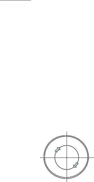
2.1.2. Swirl compensation.
Symmetrical swirl.
Figure 2-2: Symmetrical swirl
|
Operation & Installation Manual V12-V6 2010-05-31.doc |
31/05/2010 |
9/60 |
When looking at specific spots in the pipe, the local gas velocity vector may not be exactly parallel to the pipe axis. This effect can be the result of a flow velocity pattern called swirl. This is a frequently occurring velocity pattern where the gas mass in the pipe rotates as it flows. The rotation can be symmetrical with respect to the pipe axis as shown in the picture above.
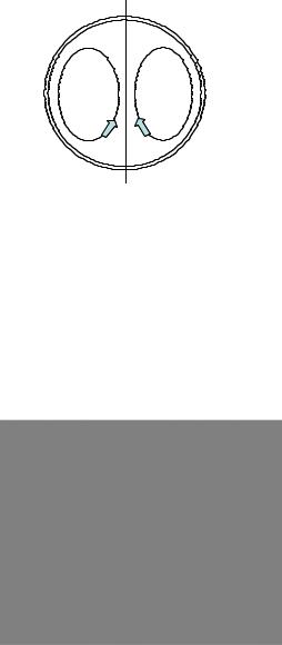
Asymmetrical swirl.
Figure 2-3: Asymmetrical swirl.
Another velocity pattern that frequently occurs, especially downstream of an elbows or bend in the pipeline, is asymmetrical swirl as shown in the picture above. The gas mass splits in two contra rotating volumes.
Swirl can disturb the gas velocity measurement as the tangential velocity component adds up with the gas velocity measured along one chord. However chords can be arranged in a way to compensate for swirl effects. Two chords arranged in the same plane intersect the flow at opposite angles (cross configuration). These chords respond to the tangential velocity component with the same magnitude but with the opposite sign.
Figure 2-4: Swirl Compensation
This allows cancellation of the swirl effect by adding or averaging the measured velocity value of both chords. Using an acoustic path with two chords in a V-shape, with a reflecting signal, has the same effect. The measured flow velocity is increased by the tangential component on one leg and decreased by the same value on the other leg.
2.1.3. Multipath ultrasonic flow meters
With an ultrasonic measuring system the measured gas velocity value is the average velocity sampled across the length of the acoustic path. Due to distortion of the gas velocity profile in the pipe this value may not be representative for the average gas velocity across the whole of the pipe cross section. In order to obtain a high accuracy the flow is sampled
|
Operation & Installation Manual V12-V6 2010-05-31.doc |
31/05/2010 |
10/60 |
using a number of measuring chords intersecting the flow in different planes, as shown in Figure 2-5.
Figure 2-5: Path configuration and pipe cross section with multiple acoustic paths.
The total volume flow is calculated by means of an integration algorithm using the results from the individual paths.
As swirl components are already compensated for in each individual measuring plane, the integration method using data from multiple paths makes the ALTOSONIC V12 highly insensitive for any kind of distortion of the flow profile.
The average speed of sound is calculated as the average of the speed of sound values measured on each of the chords. Normally these values are very close to each other.
2.2 General description.
The ALTOSONIC V12 meters consist of a meter body with an electronic unit installed on top of it (Figure 2-6). A number of ultrasonic transducers is installed inside the meter body. For an ALTOSONIC V12 six transducers are installed on one side of the meter body, four transducers are located on the other side of the meter body and two transducers are installed on the upper side of the meter.
Each pair of ultrasonic transducers constitute an acoustic path (measuring path) with 2 chords arranged in a V-shape. Five transducer pairs and the corresponding acoustic paths are located in horizontal planes perpendicular to the pipe axis.
The measured gas velocity is calculated from the data of these five horizontal planes.
Two chords are located in a vertical plane perpendicular to the axis. These are mainly used for diagnostic purposes.
The signals sent by transducers in planes that are offset from the meter centre line are reflected via acoustic mirrors to the receiving transducers. These acoustic mirrors are not required for the two paths going through centre of the meter.
|
Operation & Installation Manual V12-V6 2010-05-31.doc |
31/05/2010 |
11/60 |

Figure 2-6: Location of sensors and electronics of an ALTOSONIC V12
The transducers are electrically connected to the electronic unit on top of the meter by means of coaxial cables. The cabling is protected against mechanical damage and moisture by means of covers or a case that is welded around part of the meter body.
The coaxial cables enter the electronics enclosure through its “foot” (or support). In this foot an Ex d approved cable feed through is installed that closes this entry to the electronics enclosure Figure 2-11.
2.3 Detailed description
2.3.1. Ultrasonic transducer
Acoustic signals are transmitted and acoustic signals are received by means of ultrasonic transducers. The active part of an ultrasonic transducer is a small disk of piëzo electric ceramic in the front of the transducer. It is packaged (sealed) in a construction of metal parts and high grade epoxy. The front side of the transducer is exposed to the fluid to be measured, this results in the best efficiency for transmitting and receiving ultrasound.
The electrical signals are connected to the piëzo electric disk by means of a glass sealed feed through. This provides for an effective sealing of gas at high pressure.
The transducers have an Ex-d connector (socket, ref 1. Figure 2-7) that connects to a to an Ex d connector (plug, ref 2.) which terminates a coaxial wire (ref 3.)
A pin (ref 4.) on the connector engages with a slot in the socket (ref 5.), this makes sure the transducer is connected with the correct polarity.
The cap (ref 6.), screwed onto the socket, fastens the connector, a small screw (M2) (ref 7.) secures this cap. The transducers are fastened in the meter body using a nut with a hole in the centre (ref 8.)
A double O-ring (ref. 9) seals the pressure inside the piping effectively from the outside world.
|
Operation & Installation Manual V12-V6 2010-05-31.doc |
31/05/2010 |
12/60 |

5 |
4 |
3 |
9 |
1 |
2 |
6 |
7 |
8 |
Figure 2-7: sensor & connector assembly
The transducers are designed to meet the requirements for explosion safety according the European standards
EN 60079-18 Encapsulated “ma” EN 60079-1 Flameproof “d” and are marked accordingly as Ex II 2 G Ex d ma IIC T5
The transducers are approved by KEMA with certificate number KEMA 07ATEX0181 X
Regarding temperature, the transducers are predominantly exposed to the temperature of the flowing medium (gas). The transducers are designed and approved for a temperature range of -40 C up to +50 C (+70 C pending, type G5) and -40 C up to +100 C (type G6)
2.3.2. ALTOSONIC V12 Meter body
The meter body of the ALTOSONIC V12 can be designed and manufactured according to either one of two different concepts, depending of the nominal diameter.
For smaller meters (typically smaller than 12 inch diameter – but not limiting) the meter body is manufactured from a single piece of metal. This piece of metal is machined to a conduit for the gas flow. Holes are machined to accommodate the transducers. Covers are bolted on top and on both sides of the meter body to protect the transducers and the wiring of the transducers. The covers can be disassembled to give access to the transducers for inspection, service or repair work.
Figure 2-8 show a meter body according to this first concept (covers and electronics enclosure partly “cut away”, cabling not shown).
Larger meters (typically larger than 12 inch – but not limiting) are manufactured using a piece of pipe and flanges that are welded together. “Nozzles” are welded onto the pipe to accommodate the transducers. To protect the transducers and wiring, a case is welded around the area where the nozzles are located. This case may have bolted covers that can be disassembled to give access to the transducers for inspection, service or repair work.
|
Operation & Installation Manual V12-V6 2010-05-31.doc |
31/05/2010 |
13/60 |

Figure 2-6 show a meter body according to this second concept (without side covers and covers on top).
Figure 2-8: Small meter body
2.3.3. ALTOSONIC V12 signal converter
The ALTOSONIC V12 ultrasonic gas flow meter has a microprocessor based signal converter. This processor controls the basic flow metering process, performs all the calculations and stores a large amount of data. It offers serial ports (two RS 485 ports) to communicate with other equipment, and programmable digital outputs (pulse/frequency output and status outputs). Serial data communication to an RTU or DCS system is supported by means of various protocols. Data can also be viewed using the display module that is built in the signal converter enclosure.
2.3.4. Signal converter enclosure
The signal converter enclosure is made of stainless steel, it is explosion safe based on the Ex d method of protection.
The signal converter housing consists of three separate compartments.
Each compartment is closed with a cover with screw thread that can be removed to give access to the internals for repair (replacement) of parts. The front compartment cover has a glass window enabling to see the LCD. Optical sensors behind the glass window allow manual operation.
Figure 2-9: Converter housing
|
Operation & Installation Manual V12-V6 2010-05-31.doc |
31/05/2010 |
14/60 |
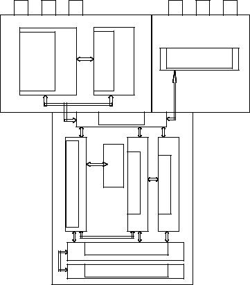
The lay out of the signal converter enclosure is as shown in the Figure 2-10 (seen from above):
LEFTSIDE |
powersupply |
|
2 X RS 485 |
|
|
|
processorboard |
|
screw terminal |
RIGHTSIDE |
module |
drivers & |
optional |
|
block |
||||||
|
|
|||||||||
|
|
|
|
|
|
|
back panel |
|
|
|
|
|
|
|
transducer interface board |
|
|
cable feed through |
processor board |
freq & I/O board |
|
|
|
|
|
|
flat |
cable interconnection |
|
|
||
|
|
|
|
|
display module |
|
|
|
||
|
|
|
|
|
|
|
FRONT |
|
|
|
Figure 2-10: Electronic compartments and location of electronics
The compartment in the front contains:
Sensor driver board: |
The transducers are connected to this board. This board |
|
controls the firing and the receiving of the acoustic pulses. |
|
Using A/D converters the signal is digitised and the information |
|
is transferred to the processor board. |
Processor board: |
This board performs all the calculations and data logging and |
|
also generates warnings and alarm signals. The calculated |
|
values and status bits of the flow meter can be transferred to |
|
the frequency & I/O board and/or to the Power module / |
|
RS485. The processor board consist of a base board with an |
|
add on module. |
Frequency & I/O board: |
The board accommodates 4 opto-couplers, each of which |
|
can be used as a status output or as frequency/pulse output. |
Backplane: |
Connections between the other boards are made by means of |
|
this board. |
Display: |
The display supports a number of information pages: 2 pages |
|
measuring data, a page with graphic data, a page with error |
|
data and a page with test data. Using the 4 light sensitive |
|
buttons these pages can be scrolled |
The compartment on the right side contains only a block with screw terminals, for connecting digital output signals.
Operation & Installation Manual V12-V6 2010-05-31.doc
31/05/2010 |
15/60 |

The compartment on the left side contains the power supply / RS485 module. Two RS 485 serial communication ports and the power supply are integrated on this circuit board. Space is available to accommodate an optional printed circuit board for future expansion of functionality.
External connections are made using edge connectors with screw terminals that connect to the printed circuit board.
2.3.5. Main Board Assembly
The main part of the signal processing consists of a number of printed circuit boards packaged in a carrier frame. The boards contained in this frame are:
•an input / output board
•the main processor board
•the sensor driver board
Attached to this frame is also the LCD display module (at the front).
The front compartment contains guides that allow the frame to slide into or out of the enclosure (when the cover is opened and after releasing the bolts).This unit connects to a printed circuit board in the back of the compartment. From this back plane the wiring connects to the other compartment and the main terminal block.
The cabling from the transducers in the meter body enters the front compartment of signal converter housing through an Ex(d) wire bushing built in the foot (support) of the enclosure (Figure 2-11).
Figure 2-11: Ex d wire bushing
2.4 Software.
2.4.1. Configuration file.
The ALTOSONIC V12 contains a powerful microprocessor that controls the functions and calculations it performs. The microprocessor executes program code consisting of several modules, according to the functions it has to perform. By means of an extensive set of parameters the software can be configured to various sizes and models of flow meters and according to specific requirements depending of applications or customers.
The parameters are stored in a configuration file, when this file is prepared a checksum is appended to it. When the file is loaded in the microprocessor system the checksum can be inspected to check that the file is not corrupted. Once loaded the checksum allows a verification that no modifications have been made since it was prepared and loaded. Configuration parameters are password protected in order to prevent unauthorized modification. Access in order to read, view and inspect parameter values is unrestricted.
|
Operation & Installation Manual V12-V6 2010-05-31.doc |
31/05/2010 |
16/60 |
Individual parameters are classified according to “roles” in order to define differentiated access rights. Each “role” is associated with a “typical” user or operator having specific responsibilities or duties. Users have to be registered with a user name and a password, when registered the role of the user is also defined, and by consequence also the access rights of that user.
The following roles have been defined, hereunder listed in according to the rank in the hierarchy.
Developer: Factory :
Service :
Calibrator :
Supervisor :
Operator:
Only a higher rank user is allowed to register a lower rank user. Multiple users having the same rank or role may be registered.
In addition to restrictions depending of the defined role of a user, a physical “overwrite disable” contact / jumper protects the configuration parameters. This disables any user from making modifications to parameters that would influence the measured flow or volume value (Figure 9-1). This prevents unintentional or unauthorized changes to the parameters and possibly invalidation of the calibration.
Normally the meter is delivered with a set of parameters suitable for the application. In case a modification of the configuration file is made, this is stored in its data logging
memory. This information can be retrieved afterwards for auditing and verification purposes. In case of a modification of the configuration file its “checksum” is also updated.
2.4.2. Start up
As the meter is powered up, the software that is stored in non volatile memory is loaded in working memory, this initialization process takes approximately 25 seconds.
A “checksum” is appended to the software, each time the software is loaded the checksum is evaluated to verify the integrity of the software.
Each time the meter is powered up this checksum of the configuration file is also inspected to verify its integrity.
When the initialization is completed the meter will automatically start its measuring function.
The following list shows the main functions performed by the software and the microprocessor :
•the basic transit time measuring process
•the flow calculations
•controlling output signals
•controlling a display
•communication with other devices
2.4.3. The basic transit time measuring process.
Measuring a single transit time for the signal to travel from one transducer to the other basically involves the following actions: Generating an electric signal to fire the transmitting
|
Operation & Installation Manual V12-V6 2010-05-31.doc |
31/05/2010 |
17/60 |
transducer (transmit pulse) and digitizing and storing the signal on the receiving transducer (receiving pulse).
Before starting the digitizing process a “receiving” window must open. The time to open and to close this window (relative to the firing time of the transmit pulse) are dependant of the size of the meter and are set as a parameters in the configuration file. This are factory settings that should not be changed.
An accurate and high resolution timer is used to control the digitizing process.
The digitized and stored signal is evaluated to detect the arrival time of the acoustic signal. As the signal is evaluated, it is checked for specific criteria to make sure it is the wanted and genuine signal and that it can be used for a reliable transit time measurement. If the signal does not meet the criteria it is rejected.
Based on the strength of the received signal, the setting of an variable gain amplifier is updated in order to match the level of the signal to the operating envelope of the digitizing circuit. The setting of the variable gain amplifier is available as a diagnostic value to indicate the strength of the received signal. To capture the level of background noise the received signal strength is also measured at a time when no signal is expected. The background noise is used to evaluate the signal to noise ratio and is also available as a diagnostic value.
The repetition rate (called sample rate, expressed as times per second) for performing a single transit time measurement can be set as a parameter in the configuration file. This is not a critical value and has no impact regarding the measured flow values.
The sample rate can be set to a value that is too high to be physically achievable, meaning the transit time does not allow such a repetition rate. In that case the meter will automatically adjust the sample rate to the highest achievable value. This value is also reported as a diagnostic value: The actual sample rate.
As a cycle the meter performs transit time measurements for all acoustic paths, each path in both directions. After completion of a cycle all results are forwarded to the flow calculation module. This includes the measured transit times, signal strength data and signal to noise ratio data. In case a measurement had failed this will be indicated: the results are marked as rejected values.
2.4.4. The flow calculation module.
The flow calculation module processes the data received from the basic transit time measuring process. After each cycle a number of variables is updated, such as
•Volume flow rate
•Average gas velocity
•Average speed of sound
•Gas velocity for each measuring path
•Speed of sound for each measuring path
•Reynolds number
•Reynolds correction factor
•Reliability
•Total (forward, accountable)
•Total (forward, not accountable)
•Total (reverse, accountable)
•Total (reverse, not accountable)
•Statistics
•Averages
The flow calculation module will also report diagnostic information as:
|
Operation & Installation Manual V12-V6 2010-05-31.doc |
31/05/2010 |
18/60 |
 Loading...