


 Loading...
SERVICE MANUAL
Models
FS-110/FS-210
JANUARY 2004
CSM-FS110
KONICA MINOLTA BUSINESS SOLUTIONS U.S.A., INC.

FS-110/FS-210 SERVICE MANUAL
JANUARY 2004
Used on Konica Models 7155/7165/FORCE 65/7255/7272

IMPORTANT NOTICE
Because of the possible hazards to an inexperienced person servicing this equipment, as well as the risk of damage to the equipment, Konica Minolta Business Solutions U.S.A., Inc. strongly recommends that all servicingbeperformedbyKonica-trainedservicetech- nicians only.
Changes may have been made to this equipment to improve its performance after this service manual was printed. Accordingly, Konica Minolta Business Solutions U.S.A., Inc., makes no representations or warranties, either expressed or implied, that the information contained in this service manual is complete or accurate. It is understood that the user of this manual must assume all risks or personal injury and/or damagetotheequipmentwhileservicingtheequipmentfor which this service manual is intended.
Corporate Publishing Department
© 2004, KONICA MINOLTA BUSINESS SOLUTIONS U.S.A., INC. All rights reserved.
Printed in U.S.A.

CONTENTS
SAFETY AND IMPORTANT WARNING ITEMS
Refer to the 7155/7165/7255/7272 service manual
on page ................................................................. |
S-1 |
CONTENTS
1. OUTLINE
FS-110/FS-210 PRODUCT SPECIFICATIONS |
........1-1 |
|
CROSS SECTION DIAGRAM ................................... |
1-4 |
|
DRIVE SYSTEM DIAGRAM ...................................... |
1-5 |
|
[1] |
Paper Conveyance Drive ........................... |
1-5 |
[2] |
Stacker Drive.............................................. |
1-6 |
[3] |
Staple Drive................................................ |
1-7 |
[4] |
Tray Drive................................................... |
1-8 |
[5] |
Folding Drive .............................................. |
1-9 |
PAPER CONVEYANCE PATH................................ |
1-10 |
|
[1] |
Paper Conveyance Path .......................... |
1-10 |
[2] |
Non-Sort Mode ......................................... |
1-11 |
[3] Sort, and Group Modes ............................ |
1-12 |
|
[4] |
Sub-tray Mode.......................................... |
1-13 |
[5] |
Staple Mode ............................................. |
1-14 |
[6] |
Booklet Mode ........................................... |
1-16 |
[7] |
Three-folding Mode .................................. |
1-17 |
2. UNIT EXPLANATION
EXTERNAL SECTION............................................... |
2-1 |
||
[1] |
Composition ............................................... |
2-1 |
|
[2] |
Mechanism................................................. |
2-1 |
|
CONVEYANCE SECTION......................................... |
2-2 |
||
[1] |
Composition ............................................... |
2-2 |
|
[2] |
Mechanism................................................. |
2-3 |
|
[3] M701 |
(FNS Conveyance) Control .............. |
2-6 |
|
[4] M712 |
(gate drive) Control........................... |
2-7 |
|
[5] SD705 (by-pass gate) Control.................... |
2-7 |
||
[6] |
M702 |
(shift) Control.................................... |
2-8 |
[7] M707 |
(paper exit roller) Control.................. |
2-9 |
|
[8]SD704 (paper exit opening solenoid)
|
Control...................................................... |
2-11 |
|
[9] |
M708 |
(paper exit opening) Control........... |
2-12 |
[10] |
M721 |
(sub-tray paper exit) Control........... |
2-13 |
MAIN TRAY SECTION ............................................ |
2-14 |
||
[1] |
Composition ............................................. |
2-14 |
|
[2] |
Mechanism............................................... |
2-14 |
|
[3] |
M703 |
(tray up/down) Control.................... |
2-15 |
STACKER SECTION............................................... |
2-17 |
||
[1] |
Composition ............................................. |
2-17 |
|
[2] |
Mechanism............................................... |
2-18 |
|
[3] |
M705 |
(alignment/U) Control ..................... |
2-21 |
[4]M716 (alignment/L) Control
|
(FS-210 only)............................................ |
2-22 |
|
[5] |
M718 |
(folding stopper) Control |
|
|
(FS-210 only)........................................... |
2-23 |
|
[6] |
M713 |
(stacker entrance) Control.............. |
2-25 |
1 OUTLINE
3 DIS./ASSEMBLY 2 UNIT EXPLANATION
MODEL |
MANUAL |
REVISED EDITION |
DATE |
PAGE |
METHOD |
7155/7165/7255/7272 |
SERVICE MANUAL |
|
Dec. 2003 |
- |
REPLACEMENT |
|
|||||
|
|
|
|
|
|
|
|
|
|
|
|

1 OUTLINE
3 DIS./ASSEMBLY 2 UNIT EXPLANATION
STAPLER SECTION .............................................. |
2-27 |
|
[1] |
Composition............................................. |
2-27 |
[2] |
Mechanism .............................................. |
2-28 |
[3] |
Stapler Movement Control....................... |
2-30 |
[4] |
Staple Control.......................................... |
2-32 |
FOLDING/THREE-FOLDING SECTION |
|
|
(FS-210 ONLY)....................................................... |
2-35 |
|
[1] |
Composition............................................. |
2-35 |
[2] |
Mechanism .............................................. |
2-36 |
[3] M719 (folding knife) Control .................... |
2-37 |
|
[4] M720 (folding conveyance) Control......... |
2-38 |
|
[5] SD706 (three-folding gate) Control.......... |
2-39 |
|
3. DISASSEMBLY/ASSEMBLY
EXTERNAL SECTION.............................................. |
3-1 |
[1]Removing and Reinstalling the Booklet
Tray (FS-210 only)..................................... |
3-1 |
[2]Removing and Reinstalling the Top
Cover/1...................................................... |
3-1 |
[3]Removing and Reinstalling the Top
Cover/2...................................................... |
3-2 |
[4]Removing and Reinstalling the Side
Cover......................................................... |
3-2 |
[5]Removing and Reinstalling the Front
Door........................................................... |
3-3 |
[6]Removing and Reinstalling the Rear
Cover......................................................... |
3-3 |
[7]Removing and Reinstalling the Main
Tray ........................................................... |
3-4 |
[8]Removing and Reinstalling the Main Paper
Exit Opening Cover ................................... |
3-5 |
[9]Removing and Reinstalling the Booklet Paper
Exit Opening Cover ................................... |
3-5 |
CONVEYANCE SECTION........................................ |
3-6 |
[1]Replacing the Paper Exit Roller
(Sponge Roller) ......................................... |
3-6 |
[2]Replacing the Intermediate Conveyance Roll-
er (Sponge Roller) ..................................... |
3-7 |
[3]Removing and Reinstalling the Paper Exit
Opening Unit.............................................. |
3-8 |
MAIN TRAY SECTION ............................................. |
3-9 |
[1]Replacing the Tray Up/down Motor
(M703) ....................................................... |
3-9 |
[2] Replacing the Up/Down Wire .................... |
3-9 |
STACKER SECTION.............................................. |
3-13 |
[1]Removing and Reinstalling the Stacker Unit
Cover....................................................... |
3-13 |
[2]Removing and Reinstalling the Stacker
Unit .......................................................... |
3-13 |
STAPLER SECTION .............................................. |
3-15 |
[1]Removing and Reinstalling the Stapler Unit
Cover....................................................... |
3-15 |
[2]Removing and Reinstalling the Clincher.. 3-16
[3] Removing and Reinstalling the Stapler ... 3-17

SAFETY WARNINGS
[1] Modifications Not Authorized by Konica Minolta
Konica Minolta equipment is renowned for their high reliability. This reliability is achieved through high-quality design and a solid service network.
Unauthorized modifications involve a high risk of degradingperformanceandsafety.Suchmodificationsaretherefore strictly prohibited. The points listed below are not exhaustive, but they illustrate the reasoning behind this policy.
 PROHIBITED ACTIONS :
(1)Using extension cables or a different power cord than specified by Konica Minolta.
(2)Using other fuses than specified by Konica Minolta. Safety will not be assured, leading to a risk of fire and injury.
(3)Disabling fuses or bridging fuse terminals with wire, metal clips, solder or similar. (This applies also to thermal fuses.)
(4)Removing air filters (except for replacement).
(5)Disabling relay functions (such as wedging paper between relay contacts, etc.).
(6)Disabling safety functions (interlocks, safety circuits, etc.). Safety will not be assured, leading to a risk of fire and injury.
(7)Performing actions to equipment not described in the instruction manual or the service handbook.
(8)Using parts other than specified by Konica Minolta.
[2] Checkpoints When Performing Onsite Service
Konica Minolta equipment is extensively tested before shipping, to ensure that all applicable safety standards are met, in order to protect the customer and customer engineer from the risk of injury. However, in daily use, any electrical equipment may be subject to parts wear and eventual failure. In order to maintain safety and reliability, thecustomerengineermustperformregularsafetychecks.
1. Advance Preparation for Safety Checks
 CAUTION:
(1)Wear clothing that facilitates work and is designed for safety.
(2)Carry out all procedures carefully to prevent injury.
(3)Be sure to disconnect the power cord of the equipment from the AC outlet.
Simply turning off the power switch is not sufficient, because paper feed units or other electrical equipment may be powered also when the power switch is turned off.
(4)Proceed with special care when performing operation checks or adjustment while the unit is powered. When carrying out operation checks or adjustment while external covers are removed, the risk of electrical shock exists when touching partswhichcarryhighvoltageorelectricalcharge. The risk of injury exists when touching moving parts such as gears or chains.
2. Safety Checkpoints
The following list is not exhaustive, but it includes actions which must be carried out at every on-site service.
 CAUTION:
(1)Check external covers and the frame for sharp edges, burrs, or nicks.
(2)Check external covers and hinges for loosening or damage.
(3)Check wiring for squeezing or damage.
(4)Check power cord for insulation problems (conductor must not be exposed).
(5)Check power cord and cable ties etc. for loosening from frame.
 WARNING:
(1)Verify that the equipment is properly grounded. If a problem is detected, establish a proper ground connection.
(2)Connecting the ground lead to an improper point such as listed below results in a risk of explosion and electric shock.
Unsuitable ground points:
-Gas pipe
-Lightning rod
-Telephone line ground
-Plastic water pipe or water pipe or faucet that has not been approved by authorities for grounding use
3. Description of Safety Checks
 CAUTION:
(1)Before performing safety check work, read all relevantdocumentation(servicehandbook,technical notices, etc.) and proceed according to the prescribed procedure, using only the prescribed tools. Do not carry out any adjustments not described in the documentation.

(2)If the power cord is damaged, replace it only with the specified power cord. If the power cord insulation has been damaged and there are exposed sections, shortcircuits and overheating may occur, leading to a serious fire risk.
(3)Do not route the power cord so that it can be stepped on or pinched. Otherwise overheating may occur, leading to a serious fire risk.
(4)When disconnecting any cables, always grasp the connector and not the cable (especially in the case of AC and high-voltage leads).
(5)Carefully remove all toner remnants from electrical parts, electrodes, etc.
(6)Make sure that wiring cannot come into contact with sharp edges, burrs, or other pointed parts.
(7)Double-check to make sure that all screws, components, wiring, connectors, etc. that were removed for safety check maintenance have been reinstalled in the original location. (Pay special attentiontoforgottenconnectors,pinchedcables, forgotten screws, etc.)
(8)When installation and preventive maintenance, verify that the power cord has been securely plugged into the AC outlet. Contact problems may lead to increased resistance, overheating, and the risk of fire.
 WARNING:
Before disassembling or adjusting the equipment, make sure that the power cord has been disconnected.
[3] Handling of Materials for Servicing
 CAUTION: Alcohol-based and acetonebased cleaners are highly flammable and must be handled with care. When using these materials for cleaning parts, observe the following precautions.
(1)Disconnect the power cord from the AC outlet.
(2)Use only a small amount of cleaner at a time and take care not to spill any liquid. If this happens, immediately wipe it off.
(3)Perform cleaning only in an environment where sufficient ventilation is assured. Breathing large quantities of organic solvents can lead to discomfort.
(4)Do not replace the cover or turntheuniton before any solvent remnants on the cleaned parts have fully evaporated.
[4] Measures to Take in Case of an Accident
(1)If an accident has occurred, the distributor who has been notified first must immediately take emergency measures to provide relief to affected persons and to prevent further damage.
(2)If a report of a serious accident has been received from a customer, an on-site evaluation must be carried out quickly and Konica Minolta must be notified.
(3)To determine the cause of the accident, conditions and materials must be recorded through direct onsite checks, in accordance with instructions issued by Konica Minolta.
(4)For reports and measures concerning accidents, consult your superior, and follow the regulations set in "Standards for the Control Program for Measures Against Electrical Equipment Accidents".
[5] Conclusion
(1)Safety of users and customer engineers depends highly on accurate maintenance and administration. Therefore, safety can be maintained by the appropriate by the proper daily service work conducted by the customer engineer.
(2)When performing service, equipment on the site must be tested for safety. The customer engineer must verify the safety of parts and ensure appropriate management of the equipment.

1 OUTLINE
1
OUTLINE

1 OUTLINE
Blank page
FS-110/FS-210
FS-110/FS-210 PRODUCT SPECIFICATIONS
[1] Type
FS-110:
Finishing device with offset collation (sort and group), stapling, and sub-tray eject features.
FS-210:
Finishing device with offset collation (sort and group), stapling, sub-tray eject, booklet (stitch- and-fold), and three-folding features.
[2] Functions
Type of Paper:
Same as the main body
Paper Size:
|
FS-110/210 |
|
FS-210 only |
|
|
NonSort/ Sta- |
SubBook- |
Three |
|
|
-fold- |
|||
|
sort group ple |
tray |
let |
ing |
|
|
|
|
|
|
A3 |
|
|
|
|
B4 |
|
|
|
|
F4R |
|
|
|
|
A4R |
|
|
*1 |
A/B |
A4 |
|
|
|
stan- |
|
|
|
|
dards B5R |
|
|
|
|
|
B5 |
|
|
|
|
A5R |
|
|
|
|
A5 |
|
|
|
|
B6R |
|
|
|
|
11 x |
|
|
|
|
17 |
|
|
|
|
8.5 x |
|
|
|
|
14 |
|
|
|
|
8.5 x |
|
|
*1 |
|
11R |
|
|
|
By |
8.5 x |
|
|
|
11 |
|
|
|
|
inch |
5.5 x |
|
|
|
|
8.5R |
|
|
|
|
5.5 x |
|
|
|
|
8.5 |
|
|
|
|
Wide |
|
|
|
|
Other |
|
|
|
*1 The position of the stopper must be changed when using paper with different size.
Paper Stacking Capacity (80g/m2 or 20lbs): Sub-tray exit mode:
Maximum 200 sheets (same-size sheets only)
Non-Staple, Group, and Offset modes:
Maximum 1500 sheets (A3, B4, F4R, 11 x 17, and 8.5 x 14)
Maximum 3000 sheets (A4, A4R, B5, B5R, 8.5 x 11, and 8.5 x 11R)
Maximum 500 sheets (A5, A5R, B6R, 5.5 x 8.5, and 5.5 x 8.5R)
Note: For FS-210, the maximum stacking capacity is 2500 sheets for A4, A4R, B5, B5R, 8.5 x 11, and 8.5 x 11R paper.
Staple Mode:
Maximum 1000 sheets (paper must be the same size)
Main-Tray Capacity
Original pages |
A3, 11 x 17, |
Other paper |
A5, and 5.5 x |
types |
|
|
8.5 |
|
|
|
|
|
|
|
2 to 9 |
50 stacks |
100 stacks |
|
|
|
10 to 20 |
50 stacks |
50 stacks |
|
|
|
21 to 30 |
30 stacks |
30 stacks |
|
|
|
31 to 40 |
25 stacks |
25 stacks |
|
|
|
41 to 50 |
20 stacks |
20 stacks |
|
|
|
Booklet Mode (FS-210 only):
•Stitch-and-fold
20 booklets with 5 sheets folded each. 15 booklets in case of small size paper (A4R/ 8.5 x 11R). One booklet with 6 sheets folded is taken as two and more booklets.
•Folding
33 booklets with 3 or less sheets folded each
25 booklets in case of small size paper (A4R/8.5 x 11R).
•Three-folding
Tray capacity is a maximum of 50 individual
folded sheets.
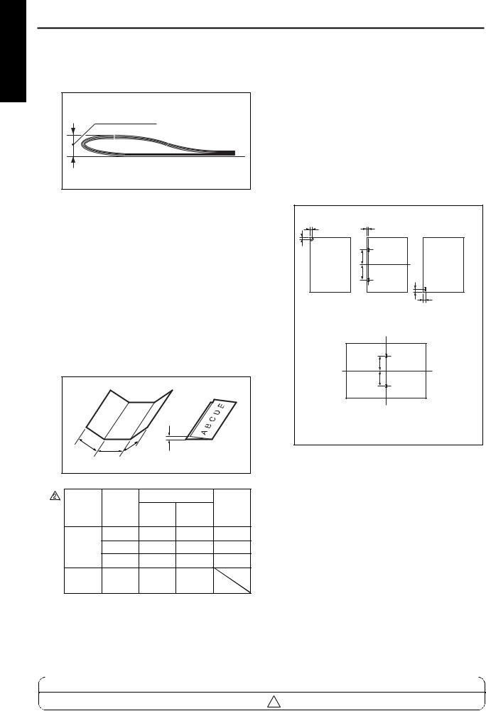
Paper curling:
10mm or less
Amount of curl |
Paper (5 sheets) |
1 OUTLINE
1-1
1 OUTLINE
FS-110/FS-210
Height of folding in the booklet mode (FS210
only): |
(80g/m2 or 20lbs) |
Height of folding |
Original |
A3, 11 x 17 |
B4, |
A4R, |
|
pages |
8.5 x 14 |
8.5 x 11R |
||
|
|
|
|
|
0 to 5 |
25mm or |
25mm or |
25mm or |
|
less |
less |
less |
||
|
||||
|
|
|
|
|
6 to 10 |
50mm or |
50mm or |
Not |
|
less |
less |
specified* |
||
|
||||
|
|
|
|
|
11 to 20 |
Not |
Not |
Not |
|
specified* |
specified* |
specified* |
||
|
||||
|
|
|
|
*The height of folding may be larger after exit, although the booklet must be folded with ease manually.
Width (a, b and c) and height (h) in the threefolding mode:
|
h |
a |
c |
|
b |
Width/ |
Mea- |
Nominal values |
Allow- |
||
sure- |
|
|
|||
height |
A4R |
8.5 x 11R |
ance |
||
ments |
|||||
|
|
|
|
||
|
a |
95mm |
89.4mm |
±2mm |
|
Width |
b |
101mm |
95mm |
±2mm |
|
|
c |
101mm |
95mm |
±2mm |
|
Height |
h |
25mm |
25mm |
|
|
or less |
or less |
|
|||
|
|
|
|||
Note: Measurements must be made using a single sheet.
Amount of sort offsetting:
30mm (after sorting and grouping)
[3] Staple Mode
Number of sheets to be stapled:
50 sheets or less (the height must be 5mm or less when using 80g/m2 or 20lbs quality paper)
Positions for stapling:
A = 8.5mm ± 3mm |
|
|
|
B = 8.5mm ± 3mm |
|
|
|
C = 60mm ± 3mm |
|
|
|
D = 8.5mm ± 3mm |
|
|
|
E = 14mm ± 3mm |
|
|
|
F = 60mm ± 3mm |
|
|
|
A |
D |
|
|
B |
C |
|
|
|
|
|
|
|
C |
E |
|
|
|
|
|
Single staple |
Two staples |
D |
Single staple |
(rear) |
|
|
(front) |
|
F |
|
|
|
F |
|
|
Booklet mode (stitch-and-fold) |
|||
|
(FS-210 only) |
|
|
Staple capacity:
5000 staples/cartridge
MODEL |
MANUAL |
REVISED EDITION |
DATE |
PAGE |
METHOD |
7155/7165/7255/7272 |
SERVICE MANUAL |
1-2 |
Dec. 2003 |
1-2 |
REPLACEMENT |
2 |
|||||
|
|
|
|
|
|
FS-110/FS-210
[4] Booklet Mode (FS-210 only)
Stitch-and-fold:
Maximum 20 sheets (when using 80g/m2 or 20lbs quality paper)
Maximum 19 sheets (when using 80g/m2 or 20lbs quality paper) + one sheet (200g/m2 or 45lbs quality paper)
Folding:
Maximum 3 sheets (when using 80g/m2 or 20lbs quality paper)
[5] Three-folding Mode (FS-210 only)
Number of three-folding:
Maximum 3 sheets (when using 80g/m2 or 20lbs quality paper)
However, special paper cannot be used.
[6] Option
PI-110
(Cover sheet feeder)
PK-110
(Puncher)
[7] Machine Specifications
Power source:
24V, 5VDC (supplied from the main body)
Maximum power consumption:
100VA
Weight:
FS-110: Approx. 55kg
FS-210: Approx. 65kg
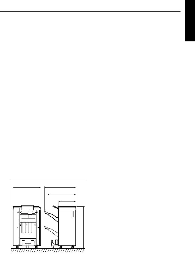
External Dimensions:
656 |
741 |
|
(tray extended) |
|
656 |
|
(tray closed) |
|
410 |
|
990 |
[8] Maintenance
Maintenance procedures:
Same as the main body
Service life:
Same as the main body
[9] Operating Environment
Temperature:
10 to 30 °C (50 °F to 86°F)
Humidity:
10 to 80% RH
Note: The information herein may be subject to change for improvement without notice.
1 OUTLINE
1-3
1 OUTLINE
FS-110/FS-210
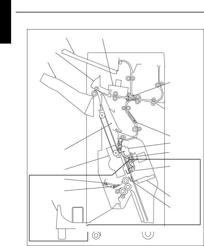
CROSS SECTION DIAGRAM
Sub-tray |
Shift unit |
Paper exit opening unit
Main tray
Alignment plate/U
Stapler
Three-folding stopper
Three-folding gate 
Booklet tray
Gate
Bypass gate  Clincher
 Flat-stapling stopper
Booklet stopper
Folding knife
Alignment plate/L
Components in the region enclosed by the dotted line represent those of FS-210.
1-4

FS-110/FS-210
DRIVE SYSTEM DIAGRAM
[1] Paper Conveyance Drive
Sub-tray paper exit roller
Sub-tray paper exit motor (M721)
Paper exit roller motor (M707)
Paper exit opening
SD (SD704)
Paper exit roller
Shift roller
Conveyance roller/B
By-pass gate SD (SD705)
By-pass gate
Paper exit opening motor (M708)
Shift motor (M702)
Sub-tray conveyance roller
Gate drive motor (M712)
FNS conveyance motor (M701)
 PI conveyance roller
Entrance roller
Conveyance roller/A
Intermediate conveyance roller
1 OUTLINE
1-5
1 OUTLINE
FS-110/FS-210
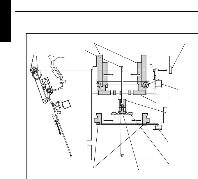
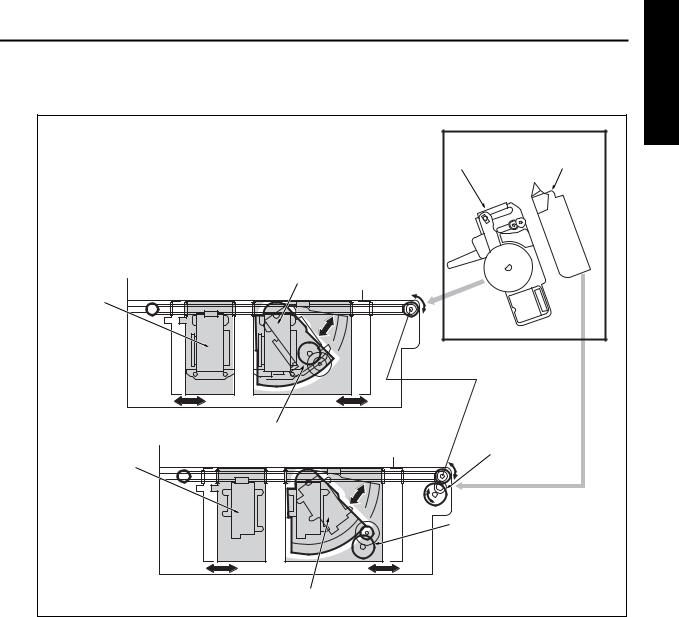
[2] Stacker Drive
Alignment plate/U |
From paper exit roller motor (M707) |
|
Paper exit arm
Alignment motor/U (M705)
Stacker entrance motor |
(M713) |
Stacker entrance roller |
Flat-stapling stopper |
Alignment motor/L (M716)
Booklet stopper
Alignment plate/L
Stopper motor (M718)
1-6
FS-110/FS-210
[3] Staple Drive
|
Stapler |
Clincher |
Stapler/R |
|
|
Stapler/F |
|
|
Stapler rotation motor (M706) |
Stapler movement |
|
|
motor (M711) |
|
Clincher/F |
|
|
|
Clincher rotation motor |
|
|
(M704) |
|
Clincher/R |
|
|
1 OUTLINE
1-7
1 OUTLINE
FS-110/FS-210
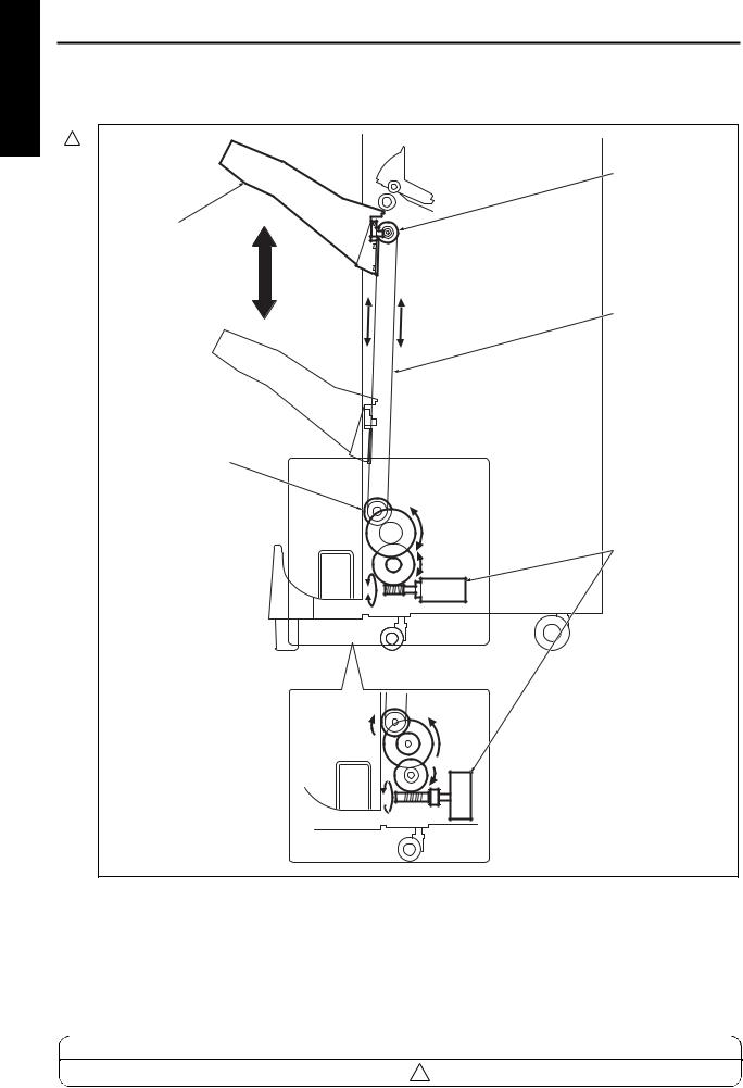
[4] Tray Drive
2
Up/down pulley/U
Main tray
Up/down wire
Old type
Up/down pulley/L
Tray up/down motor (M703)
New type
fs2101001
MODEL |
MANUAL |
REVISED EDITION |
DATE |
PAGE |
METHOD |
7155/7165/7255/7272 |
SERVICE MANUAL |
1-8 |
Dec. 2003 |
1-8 |
REPLACEMENT |
2 |
|||||
|
|
|
|
|
|
FS-110/FS-210
[5] Folding Drive
Folding roller
Three-folding gate
 Folding knife
|
Folding knife motor |
Three-folding gate SD |
(M719) |
(SD706) |
|
Three-folding roller
Folding conveyance motor (M720)
1 OUTLINE
1-9
1 OUTLINE
FS-110/FS-210
PAPER CONVEYANCE PATH
[1] Paper Conveyance Path
The finisher (FNS) consists of five paper paths, as shown in the diagram below.
Sheets are turned over by the main body's exit page inverter, and then passed to the FNS.
The FNS has two paper entrance connections: one from the main body, and the other from PI-110 (optional).
Sub-tray
PI-110
Main tray |
2 |
1 3 
1 |
2 |
 Main body
3 4 5
3
4 5
5
Booklet tray
4
5
Paper conveyance path |
Finishing mode |
||
1 |
|
Non-sort, sort, and group modes |
|
|
|
|
|
|
12 |
|
Sub-tray mode |
|
|
|
|
3Staple mode
4Booklet mode (FS-210 only)
5Three-folding mode (FS-210 only)
1-10
FS-110/FS-210
[2] Non-Sort Mode
In the non-sort mode, the gate is set to the position to carry paper to the main tray. Each sheet, delivered from the main body, is carried to the main tray through the gate.
Entrance roller |
Main tray |
Gate |
Paper exit roller |
Conveyance roller/A |
1 OUTLINE
1-11
1 OUTLINE
FS-110/FS-210
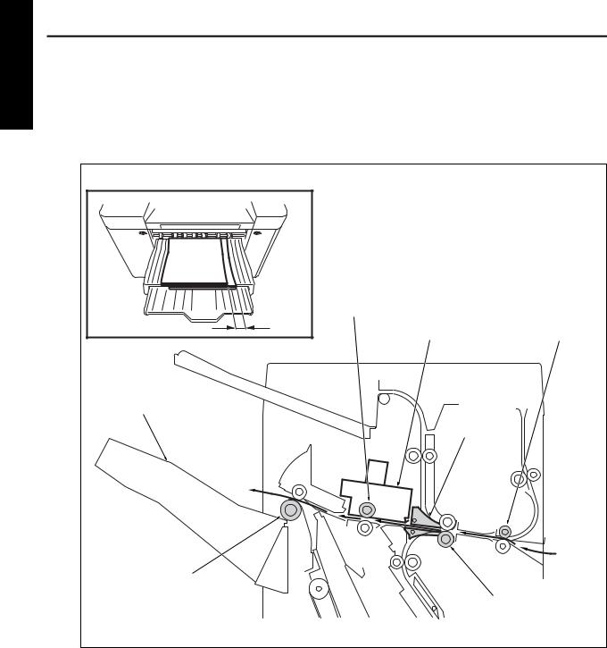
[3] Sort, and Group Modes
In the sort and group modes, the gate is set to the position to carry paper to the main tray. Each sheet, delivered from the main body, is conveyed to the main tray while the sheet is shifted by 30mm to the rear. The shift roller of the shift unit performs the shift action. In the sort mode, even pages are offset. In the group mode, even numbered copies are offset.
Shift roller |
|
30mm |
Entrance roller |
Shift unit |
|
Main tray |
|
|
Gate |
Paper exit roller |
|
|
Conveyance roller A |
1-12
FS-110/FS-210
[4] Sub-tray Mode
In the sub-tray mode, the gate is set to the position to carry paper to the sub-tray. Each sheet, delivered from the main body, is delivered to the sub-tray
Sub-tray |
Entrance roller |
Sub-tray paper exit roller |
Gate |
Sub-tray conveyance roller |
Conveyance roller/A |
1 OUTLINE
1-13
1 OUTLINE
FS-110/FS-210
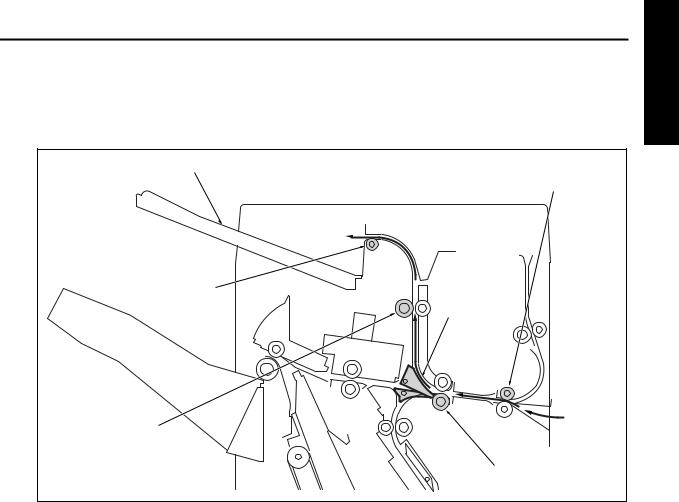
[5] Staple Mode
For sheets of all size except A4, B5, and 8.5 x 11:
(1)The gates are set to the position to carry paper to the stacker.
(2)If paper is larger than A4R, the paper exit opening will open.
(3)Each sheet is carried to the flat-stapling stopper and its vertical position (feeding direction) is adjusted.
(4)The horizontal position (widthwise direction) of each sheet is adjusted by the alignment plate/U.
(5)When all necessary sheets are stacked, they are stapled with the stapler and the clincher.
(6)The set of stapled sheets is delivered by the paper exit arm to the main tray.
(7)Steps (3) through (6) are repeated for each set of sheets to be stapled.
Paper exit opening unit |
Entrance roller |
Main tray
Gate
|
Conveyance roller/A |
Alignment plate/U |
Conveyance roller/B |
Paper exit belt 
Intermediate conveyance roller
Stacker entrance roller
Swing belt
Stapler
Clincher
Paper exit arm
Flat-stapling stopper
1-14
FS-110/FS-210
For sheets of A4, B5, and 8.5 x 11:
(1)The first set is stapled and delivered to the main tray in the same manner as sheets of all size except A4, B5, and 8.5 x 11.
(2)As the front of the first set is being discharged, the stacker entrance roller stops and the by-pass gate opens. The first sheet of the second set (and subsequent sets) is conveyed to the stacker entrance.
(3)The by-pass gate closes, and a second sheet is laid over the first sheet which is fixed by the stacker entrance roller.
(4)When the front of the first set has been delivered, the stacker entrance roller starts to rotate. The first and second sheets are conveyed to the stacker.
(5)The alignment plate/U lines up each sheet in the widthwise direction.
(6)When all sheets are stacked, they are stapled with the stapler and the clincher.
(7)The set of stapled sheets is delivered by the paper exit arm to the main tray.
(8)Steps (2) through (7) are repeated for each set of sheets.
Paper exit opening unit |
Entrance roller |
Main tray
Gate
|
|
Conveyance roller/A |
|
|
Conveyance roller/B |
Alignment plate/U |
Second |
First sheet |
|
sheet |
|
Paper exit belt |
|
By-pass gate |
|
Intermediate |
|
|
|
|
|
|
conveyance roller |
|
|
Stacker entrance roller |
|
|
Intermediate conveyance |
|
|
roller |
Stapler |
|
Clincher |
|
|
|
Paper exit arm |
|
|
Flat-stapling stopper |
|
|
1 OUTLINE
1-15
1 OUTLINE |
|
FS-110/FS-210 |
|
||
|
|
|
|
||
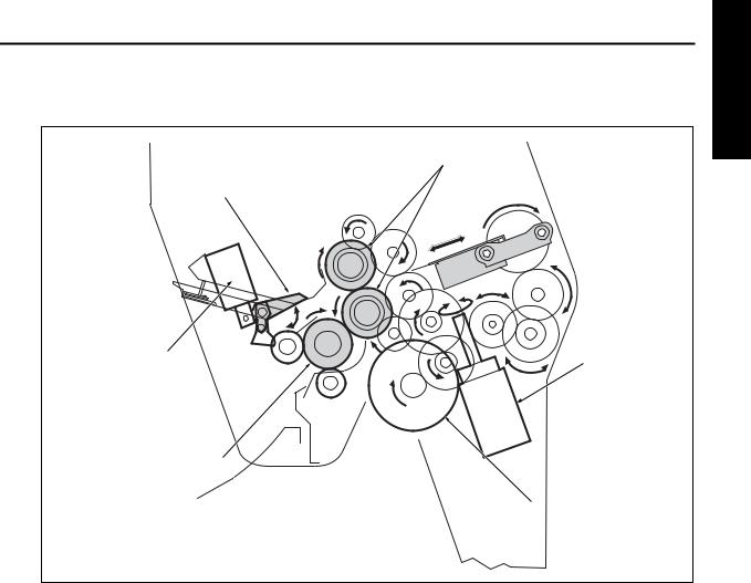
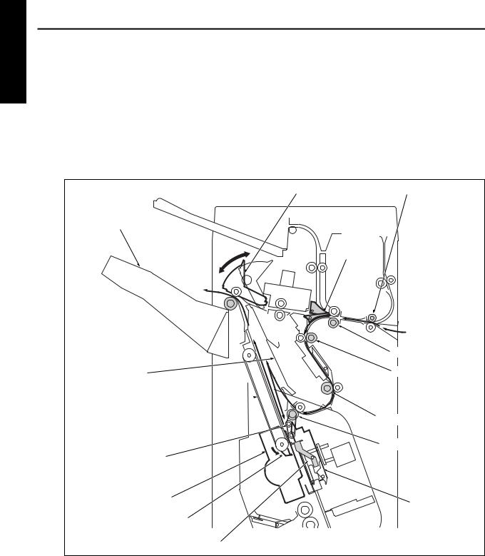
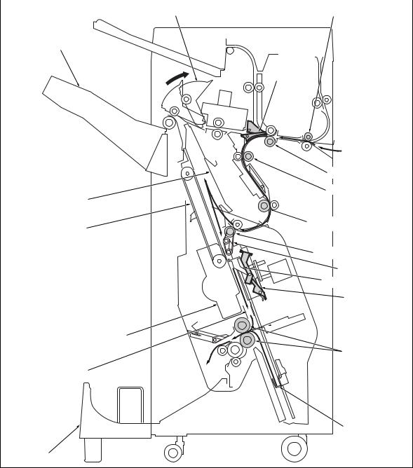
[6] Booklet Mode |
|
||||
|
|
(1) |
The gates are set to the position to carry paper to the stacker. |
|
|
|
|
(2) |
The paper exit opening opens. |
|
|
|
|
(3) The booklet stopper lowers to the stitch-and-fold position. The flat-stapling stopper is released as the |
|||
|
|
|
|
booklet stopper lowers. |
|
|
|
(4) |
The paper is conveyed to the booklet stopper to line up sheets in the lengthwise direction. |
||
|
|
(5) |
The alignment plate/U and alignment plate/L line up each sheet in the widthwise direction. |
||
|
|
(6) |
When the stitch-and-fold mode is selected, the sheets are stapled by the stapler and the clincher. |
||
|
|
(7) |
The booklet stopper lowers to the folding position for setting the paper to the folding position. |
||
|
|
(8) |
The folding knife and the folding roller fold the sheets, which are delivered to the booklet tray. |
||
|
|
|
|
|
|
|
|
|
|
Paper exit opening unit |
Entrance roller |
|
|
|
|
Main tray |
|
|
|
|
|
|
Gate |
Conveyance roller/A
Conveyance roller/B
Alignment plate/U
Paper exit belt
Intermediate conveyance
roller
Stacker entrance roller
Swing belt
Flat-stapling stopper
 Clincher
 Folding knife
Stapler
Folding roller
Alignment plate/L
Booklet stopper
Booklet tray
1-16
|
FS-110/FS-210 |
|
1 OUTLINE |
|
|
||
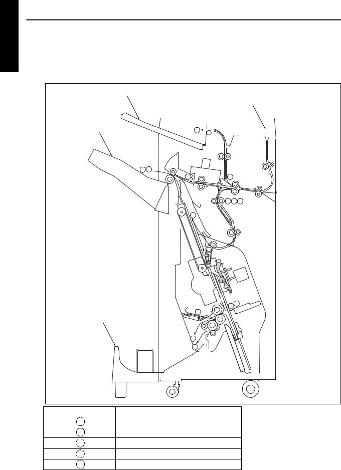
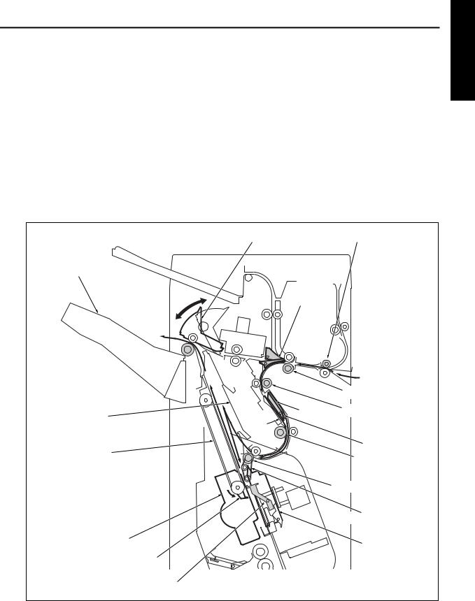
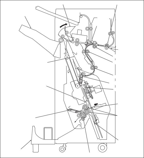
[7] Three-folding Mode |
|||
(1) |
The gates are set to the position to carry paper to the stacker. |
|
|
(2) |
The paper exit opening opens. |
|
|
(3) The booklet stopper lowers to the stitch-and-fold position. The flat-stapling stopper is released as the |
|
|
|
|
booklet stopper lowers. |
|
|
(4) |
The paper is conveyed to the booklet stopper to line up in the lengthwise direction. |
|
|
(5) |
The alignment plate/U and the alignment plate/L line up each sheet in the widthwise direction. |
|
|
(6) |
The booklet stopper lowers to the first folding position, and the sheet is set to the first folding position. |
|
|
(7) The folding knife and the folding roller perform the first folding, and the paper is conveyed toward the threefolding stopper.
(8) The three-folding stopper curls the sheet, and the second folding is made by drawing it to the three-folding roller. The three-folded sheet is delivered to the booklet tray.
Paper exit opening unit Entrance roller
Main tray
Gate
|
Conveyance roller/A |
Alignment plate/U |
Conveyance roller/B |
Intermediate conveyance roller
Stacker entrance roller
Alignment plate/L
 Flat-stapling stopper
Folding knife
Folding roller
Three-folding stopper
Booklet stopper
Booklet tray
Three-folding stopper
1-17

1 OUTLINE
Blank page
Loading...