


 Loading...
SERVICE MANUAL
MODEL
FS-112
Finisher Unit
NOVEMBER 2002
CSM-FS112

FS-112
SERVICE MANUAL
Used On Model 7145
November 2002

IMPORTANT NOTICE
Because of the possible hazards to an inexperienced person servicing this equipment, as well as the risk of damage to the equipment, Konica Business Technologies strongly recommends that all servicing be performed by Konica-trained service technicians only.
Changes may have been made to this equipment to improve its performance after this service manual was printed. Accordingly, Konica Business Technologies, Inc., makes no representations or warranties, either expressed or implied, that the information contained in this service manual is complete or accurate. It is understood that the user of this manual must assume all risks or personal injury and/or damage to the equipment while servicing the equipment for which this service manual is intended.
Corporate Publishing Department
© 2002, KONICA BUSINESS TECHNOLOGIES, INC. All rights reserved.
Printed in U.S.A.

CONTENTS
CONTENTS
SAFETY AND IMPORTANT WARNING ITEMS
Refer to the 7145 service manual on page . . . . . . . . . . . . . . . . . . . . . . . . . . . . . . . . . . . . . . . . . . . . . . . . S-1
I OUTLINE
1. FS-112 PRODUCT SPECIFICATIONS . . . . . . . . . . . . . . . . . . . . . . . . . . . . . . . . . . . . . . . . . . . . . . . . 1-1 2. CENTER CROSS-SECTIONAL DIAGRAM . . . . . . . . . . . . . . . . . . . . . . . . . . . . . . . . . . . . . . . . . . . . . 1-5 3. DRIVE SYSTEM DIAGRAM . . . . . . . . . . . . . . . . . . . . . . . . . . . . . . . . . . . . . . . . . . . . . . . . . . . . . . . . . 1-6 3.1 Conveyance/Paper exit section . . . . . . . . . . . . . . . . . . . . . . . . . . . . . . . . . . . . . . . . . . . . . . . . . . . 1-6 3.2 Alignment section . . . . . . . . . . . . . . . . . . . . . . . . . . . . . . . . . . . . . . . . . . . . . . . . . . . . . . . . . . . . . 1-7 3.3 Stapler section. . . . . . . . . . . . . . . . . . . . . . . . . . . . . . . . . . . . . . . . . . . . . . . . . . . . . . . . . . . . . . . . 1-7 3.4 Tray section . . . . . . . . . . . . . . . . . . . . . . . . . . . . . . . . . . . . . . . . . . . . . . . . . . . . . . . . . . . . . . . . . . 1-8
II UNIT EXPLANATION
1. CONVEYANCE SECTION . . . . . . . . . . . . . . . . . . . . . . . . . . . . . . . . . . . . . . . . . . . . . . . . . . . . . . . . . . 2-1 1.1 Composition. . . . . . . . . . . . . . . . . . . . . . . . . . . . . . . . . . . . . . . . . . . . . . . . . . . . . . . . . . . . . . . . . . 2-1 1.2 Operation. . . . . . . . . . . . . . . . . . . . . . . . . . . . . . . . . . . . . . . . . . . . . . . . . . . . . . . . . . . . . . . . . . . . 2-2 1.2.1 Conveyance control . . . . . . . . . . . . . . . . . . . . . . . . . . . . . . . . . . . . . . . . . . . . . . . . . . . . . . . 2-2 2. PAPER EXIT SECTION . . . . . . . . . . . . . . . . . . . . . . . . . . . . . . . . . . . . . . . . . . . . . . . . . . . . . . . . . . . . 2-3
2.1 Composition. . . . . . . . . . . . . . . . . . . . . . . . . . . . . . . . . . . . . . . . . . . . . . . . . . . . . . . . . . . . . . . . . . 2-3 2.2 Operation. . . . . . . . . . . . . . . . . . . . . . . . . . . . . . . . . . . . . . . . . . . . . . . . . . . . . . . . . . . . . . . . . . . . 2-4 2.2.1 Paper exit control . . . . . . . . . . . . . . . . . . . . . . . . . . . . . . . . . . . . . . . . . . . . . . . . . . . . . . . . . 2-4 2.2.2 Paper stack control . . . . . . . . . . . . . . . . . . . . . . . . . . . . . . . . . . . . . . . . . . . . . . . . . . . . . . . 2-5 2.2.3 Shutter control . . . . . . . . . . . . . . . . . . . . . . . . . . . . . . . . . . . . . . . . . . . . . . . . . . . . . . . . . . . 2-6 3. ALIGNMENT SECTION . . . . . . . . . . . . . . . . . . . . . . . . . . . . . . . . . . . . . . . . . . . . . . . . . . . . . . . . . . . . 2-7
3.1 Composition. . . . . . . . . . . . . . . . . . . . . . . . . . . . . . . . . . . . . . . . . . . . . . . . . . . . . . . . . . . . . . . . . . 2-7 3.2 Operation. . . . . . . . . . . . . . . . . . . . . . . . . . . . . . . . . . . . . . . . . . . . . . . . . . . . . . . . . . . . . . . . . . . . 2-8 3.2.1 Paper alignment control . . . . . . . . . . . . . . . . . . . . . . . . . . . . . . . . . . . . . . . . . . . . . . . . . . . . 2-8 4. STAPLER SECTION . . . . . . . . . . . . . . . . . . . . . . . . . . . . . . . . . . . . . . . . . . . . . . . . . . . . . . . . . . . . . 2-12
4.1 Composition. . . . . . . . . . . . . . . . . . . . . . . . . . . . . . . . . . . . . . . . . . . . . . . . . . . . . . . . . . . . . . . . . 2-12 4.2 Operation. . . . . . . . . . . . . . . . . . . . . . . . . . . . . . . . . . . . . . . . . . . . . . . . . . . . . . . . . . . . . . . . . . . 2-13 4.2.1 Stapler control . . . . . . . . . . . . . . . . . . . . . . . . . . . . . . . . . . . . . . . . . . . . . . . . . . . . . . . . . . 2-13 4.2.2 Staple control . . . . . . . . . . . . . . . . . . . . . . . . . . . . . . . . . . . . . . . . . . . . . . . . . . . . . . . . . . . 2-14 5. TRAY SECTION . . . . . . . . . . . . . . . . . . . . . . . . . . . . . . . . . . . . . . . . . . . . . . . . . . . . . . . . . . . . . . . . . 2-15
5.1 Composition. . . . . . . . . . . . . . . . . . . . . . . . . . . . . . . . . . . . . . . . . . . . . . . . . . . . . . . . . . . . . . . . . 2-15 5.2 Operation. . . . . . . . . . . . . . . . . . . . . . . . . . . . . . . . . . . . . . . . . . . . . . . . . . . . . . . . . . . . . . . . . . . 2-16 5.2.1 Detection of the lower limit of the tray . . . . . . . . . . . . . . . . . . . . . . . . . . . . . . . . . . . . . . . . 2-16 5.2.2 Tray count . . . . . . . . . . . . . . . . . . . . . . . . . . . . . . . . . . . . . . . . . . . . . . . . . . . . . . . . . . . . . 2-16 5.2.3 Tray up/down control while in print operation. . . . . . . . . . . . . . . . . . . . . . . . . . . . . . . . . . . 2-16
III DISASSEMBLY/ASSEMBLY
1. EXTERNAL SECTION . . . . . . . . . . . . . . . . . . . . . . . . . . . . . . . . . . . . . . . . . . . . . . . . . . . . . . . . . . . . . 3-1 1.1 Removing and reinstalling of the FNS . . . . . . . . . . . . . . . . . . . . . . . . . . . . . . . . . . . . . . . . . . . . . . 3-1 2. STAPLER SECTION . . . . . . . . . . . . . . . . . . . . . . . . . . . . . . . . . . . . . . . . . . . . . . . . . . . . . . . . . . . . . . 3-2
I OUTLINE
III DIS./ASSEMBLY II UNIT EXPLANATION
iii

I OUTLINE
III DIS./ASSEMBLY II UNIT EXPLANATION
CONTENTS
2.1 Removing and reinstalling of the stapler unit . . . . . . . . . . . . . . . . . . . . . . . . . . . . . . . . . . . . . . . . . 3-2 2.2 Replacing the stapler cartridge . . . . . . . . . . . . . . . . . . . . . . . . . . . . . . . . . . . . . . . . . . . . . . . . . . . 3-3 3. PAPER EXIT SECTION . . . . . . . . . . . . . . . . . . . . . . . . . . . . . . . . . . . . . . . . . . . . . . . . . . . . . . . . . . . . 3-4 3.1 Removing and reinstalling of the paper exit roller /A . . . . . . . . . . . . . . . . . . . . . . . . . . . . . . . . . . . 3-4 3.2 Removing and reinstalling of the tray. . . . . . . . . . . . . . . . . . . . . . . . . . . . . . . . . . . . . . . . . . . . . . . 3-6 3.3 Removing and reinstalling of the up/down wire . . . . . . . . . . . . . . . . . . . . . . . . . . . . . . . . . . . . . . . 3-8
iv

FS-112 PRODUCT SPECIFICATIONS
I OUTLINE
1. FS-112 PRODUCT SPECIFICATIONS
A. Type
Type: |
Built-in type compact finisher (multiple trays type) |
Option: |
Finisher tray [FT-107] Up to two trays can be installed (up to 4 |
|
trays in total together with the standard trays) |
B. Functions
Applicable copy paper: |
Same as the main body |
|
|
|||
Paper size: |
|
|
|
|
|
|
|
|
|
|
|
|
|
|
|
Non-sort |
Sort/group |
|
1 staple |
2 staples |
|
|
|
|
|
|
|
Metric series |
A3 |
! |
! |
|
! |
! |
|
|
|
|
|
|
|
|
B4 |
! |
! |
|
! |
! |
|
|
|
|
|
|
|
|
F4 |
! |
! |
|
! |
! |
|
|
|
|
|
|
|
|
A4R |
! |
! |
|
! |
! |
|
|
|
|
|
|
|
|
A4 |
! |
! |
|
! |
! |
|
|
|
|
|
|
|
|
B5R |
! |
! |
|
! |
! |
|
|
|
|
|
|
|
|
B5 |
! |
! |
|
! |
! |
|
|
|
|
|
|
|
|
A5R |
! |
|
|
! |
! |
|
|
|
|
|
|
|
|
B6R*1 |
! |
|
|
|
|
|
|
|
|
|
|
|
Inch series |
11 x 17 |
! |
! |
|
! |
! |
|
|
|
|
|
|
|
|
8.5 x 14 |
! |
! |
|
! |
! |
|
|
|
|
|
|
|
|
8.5 x 11R |
! |
! |
|
! |
! |
|
|
|
|
|
|
|
|
8.5 x 11 |
! |
! |
|
! |
! |
|
|
|
|
|
|
|
|
5.5 x 8.5R |
! |
! |
|
! |
! |
|
|
|
|
|
|
|
Non-standard size |
! |
|
|
|
|
|
|
|
|
|
|
|
|
*1 Only for metric area |
|
|
|
|
|
|
Maximum paper capacity: |
2 trays: 100 + 1000 = 1100 sheets |
|
||||
|
|
3 trays: 100 + 100 + 600 = 800 sheets |
|
|||
|
|
4 trays: 100 x 4 = 400 sheets |
|
|
||
Stack capacity (80g/m2 or 20lbs high-quality paper)
•2-trays specification (standard)
|
|
Small size |
Medium size |
Large size |
Special paper |
Non-standard |
|
|
|
|
|
|
paper |
|
|
|
|
|
|
|
Tray 1 |
Non-staple |
100 sheets |
100 sheets |
100 sheets |
10 sheets |
10 sheets |
|
|
|
|
|
|
|
|
Staple |
10 sets |
10 sets |
10 sets |
— |
— |
|
|
|
|
|
|
|
Tray 2 |
Non-staple |
— |
1000 sheets |
300 sheets |
50 sheets |
— |
|
|
|
|
|
|
|
|
Staple |
— |
50 sets |
20 sets |
— |
— |
|
|
|
|
|
|
|
I OUTLINE
1-1
FS-112 PRODUCT SPECIFICATIONS
•3-trays specification
|
|
|
|
|
|
|
|
|
|
|
|
|
Small size |
Medium size |
Large size |
Special paper |
Non-standard |
OUTLINE |
|
|
|
|
|
|
|
paper |
|
|
|
|
|
|
|
|
|
|
Tray 1 |
Non-staple |
100 sheets |
100 sheets |
100 sheets |
10 sheets |
10 sheets |
|
|
|
|||||||
|
|
|
|
|
|
|
|
|
|
|
|
Staple |
10 sets |
10 sets |
10 sets |
— |
— |
|
|
|
|
|
|
|
|
|
I |
|
Tray 2 |
Non-staple |
— |
100 sheets |
100 sheets |
10 sheets |
— |
|
|
|
|
|
|
|
|
|
|
|
|
Staple |
— |
10 sets |
10 sets |
— |
— |
|
|
|
|
|
|
|
|
|
|
|
Tray 3 |
Non-staple |
— |
600 sheets |
200 sheets |
50 sheets |
— |
|
|
|
|
|
|
|
|
|
|
|
|
Staple |
— |
30 sets |
15 sets |
— |
— |
|
|
|
|
|
|
|
|
|
•4-trays specification
|
|
Small size |
Medium size |
Large size |
Special paper |
Non-standard |
|
|
|
|
|
|
paper |
|
|
|
|
|
|
|
Tray 1 |
Non-staple |
100 sheets |
100 sheets |
100 sheets |
10 sheets |
10 sheets |
|
|
|
|
|
|
|
|
Staple |
10 sets |
10 sets |
10 sets |
— |
— |
|
|
|
|
|
|
|
Tray 2 |
Non-staple |
— |
100 sheets |
100 sheets |
10 sheets |
— |
|
|
|
|
|
|
|
|
Staple |
— |
10 sets |
10 sets |
— |
— |
|
|
|
|
|
|
|
Tray 3 |
Non-staple |
— |
100 sheets |
100 sheets |
10 sheets |
— |
|
|
|
|
|
|
|
|
Staple |
— |
10 sets |
10 sets |
— |
— |
|
|
|
|
|
|
|
Tray 4 |
Non-staple |
— |
100 sheets |
100 sheets |
10 sheets |
— |
|
|
|
|
|
|
|
|
Staple |
— |
10 sets |
10 sets |
— |
— |
|
|
|
|
|
|
|
Small size |
: |
B6R, A5R, 5.5 x 8.5R |
Medium size : |
A4, A4R, B5, B5R, 8.5 x 11, 8.5 x 11R |
|
Large size |
: |
A3, B4, F4, 11 x 17, 8.5 x 14 |
Special paper*1: |
Thin paper (Less than 60g/m2 or 16lbs), thick paper (over 128g/m2 |
|
|
|
or 32lbs), blueprint master, OHP, etc. |
*1 Sort, staple not allowed
Note:
•The above figures apply to when papers of the same size are stacked continuously.
•The number of stacked sheets in staple mode must not exceed the stack sheet capacity for non-staple mode.
Paper curling (5 sheets) : |
h = 10mm or less |
h
Amount of sort off-setting: |
30mm |
(during sorting/grouping) |
20mm (A5R, 5.5 x 8.5R) |
1-2
|
|
|
|
|
|
|
|
|
|
|
|
|
|
|
|
|
|
|
|
|
|
|
|
|
|
|
|
FS-112 PRODUCT SPECIFICATIONS |
|
|
|
|
|
|
|
|
|
|
|
|
|
|
|
|
|
|
|
|
|
|
|
|
|
|
|
|
|
|
|
C. Staple mode |
|
|
|
|
|
|
|
|
|
|
|
|
|
|
|
|
|
|
|
|
|
|
|
|
|
|
|||
|
Staple ability: |
|
|
|
|
|
Maximum 50 sheets (with 80g/m2 or 20lbs paper, paper thickness |
||||||||||||||||||||||
|
|
|
|
|
|
|
|
|
less than 5mm) |
||||||||||||||||||||
|
Staple capacity: |
|
|
|
|
|
5,000 staples/cartridge |
||||||||||||||||||||||
|
Staple position: |
|
|
|
|
|
|
|
|
|
|
|
|
|
|
|
|
|
|
|
|
|
|
|
|
|
|
||
|
|
|
|
|
|
|
|
|
|
|
|
|
|
|
|
|
|
|
|
|
|
|
|
|
|
|
|
|
|
|
|
|
|
|
|
|
|
|
|
|
|
|
|
|
|
|
|
|
|
|
|
|
|
|
|
|
|
|
|
|
|
|
|
|
|
|
|
|
|
|
|
|
|
|
|
|
|
|
|
|
|
|
|
|
|
|
|
|
|
|
|
|
|
|
|
|
|
|
|
|
|
|
|
|
|
|
|
|
|
|
|
|
|
|
|
|
|
|
|
|
|
|
|
|
|
|
|
|
|
|
|
|
|
|
|
|
|
|
|
|
|
|
|
|
|
|
|
|
|
|
|
|
|
|
|
|
|
|
|
|
|
|
|
|
|
|
|
|
|
|
|
|
|
|
|
|
|
|
|
|
|
|
|
|
|
|
|
|
|
|
|
|
|
|
|
|
|
|
|
|
|
|
|
|
|
|
|
|
|
|
|
|
|
|
|
|
|
|
|
|
|
|
|
|
|
|
|
|
|
|
|
|
|
|
|
|
|
|
|
|
|
|
|
|
|
|
|
|
|
|
|
|
|
|
|
|
|
|
|
|
|
|
|
|
|
|
|
|
|
|
|
|
|
|
|
|
|
|
|
|
|
|
|
|
|
|
|
|
|
|
|
|
|
|
|
|
|
|
|
|
|
|
|
|
|
|
|
|
|
|
|
|
|
|
|
|
|
|
|
|
|
|
|
|
|
|
|
|
|
|
|
|
|
|
|
|
|
|
|
|
|
|
|
|
|
|
|
|
|
|
|
|
|
|
|
|
|
|
|
|
|
|
|
|
|
|
|
|
|
|
|
|
|
|
|
|
|
|
|
|
|
|
|
|
|
|
|
|
|
|
|
|
|
|
|
|
|
|
|
|
|
|
|
|
|
|
|
|
|
|
|
|
|
|
|
|
|
|
|
|
|
|
|
|
|
|
|
|
|
|
|
|
|
|
|
|
|
|
|
|
|
|
|
|
|
|
|
|
|
|
|
|
|
|
|
|
|
|
|
|
|
|
|
|
|
|
|
|
|
|
|
|
|
|
|
|
|
|
|
|
|
|
|
|
|
|
|
|
|
|
|
|
|
|
|
|
|
|
|
|
|
|
|
|
|
|
|
|
|
|
|
|
|
|
|
|
|
|
|
|
|
|
|
|
|
|
|
|
|
|
|
|
|
|
|
|
|
|
|
|
|
|
|
|
|
|
|
|
|
|
|
|
|
|
|
|
|
|
|
|
|
|
|
|
|
|
|
|
|
|
|
|
|
|
|
|
|
|
|
|
|
|
|
|
|
|
|
|
|
|
|
|
|
|
|
|
|
|
|
|
|
|
|
|
|
|
|
|
|
|
|
|
|
|
|
|
|
|
|
|
|
|
|
|
|
|
|
|
|
|
|
|
|
|
|
|
|
|
|
|
|
|
|
|
|
|
|
|
|
|
|
|
|
|
|
|
|
|
|
|
|
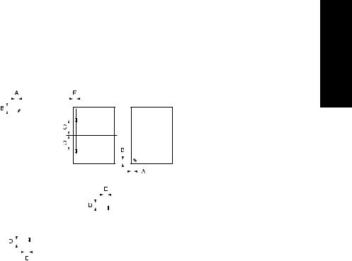
A = 8.6mm ± 3mm |
|
|
|
B = 8.6mm ± 3mm |
|
|
|
C = refer to following table |
|
|
|
D = 10.5mm ± 3mm |
|
|
|
E = 8.0mm ± 3mm |
|
|
|
|
|
|
Paper Size |
|
C (mm) |
|
|
|
|
A3/A4 |
|
60 ± 4 |
|
|
|
|
|
B4/B5 |
|
53 ± 4 |
|
|
|
|
|
A4R |
|
90 ± 4 |
|
|
|
|
|
B5R |
|
80 ± 4 |
|
|
|
|
|
A5R |
|
63 ± 4 |
|
|
|
|
|
F4 |
(8 x 13) |
|
90 ± 4 |
|
|
|
|
F4 |
(8.125 x 13, 8.125 x 13.25) |
|
91.5 ± 4 |
|
|
|
|
F4 |
(8.25 x 13) |
|
93 ± 4 |
|
|
|
|
F4 |
(8.5 x 13) |
|
95 ± 4 |
|
|
|
|
11 x 17/8.5 x 11 |
|
52 ± 4 |
|
|
|
|
|
8.5 x 14/8.5 x 11R |
|
95 ± 4 |
|
|
|
|
|
5.5 x 8.5R |
|
60 ± 4 |
|
|
|
|
|
I OUTLINE
1-3

I OUTLINE
FS-112 PRODUCT SPECIFICATIONS
D. Machine data
Power source: |
24VDC/5V (supplied from the main body) |
Power consumption: |
Maximum 70VA |
Weight: |
Approx. 13kg |
Dimensions: |
707mm (W) x 507mm (D) x 392mm (H) |
E. |
Maintenance and life |
|
Maintenance: |
Same as the main body |
|
Machine service life: |
Same as the main body |
|
F. |
Operating environment |
|
Temperature: |
10°C to 30°C (50°F to 86°F) |
|
Humidity: |
10% RH% to 80% RH |
|
Note:
• The information herein may be subject to change for improvement without notice.
1-4
CENTER CROSS-SECTIONAL DIAGRAM
2. CENTER CROSS-SECTIONAL DIAGRAM
|
[6] |
[7] |
[8] |
[9] |
|
[5] |
|
|
OUTLINEI |
|
|
|
|
|
|
[4] |
|
|
|
|
[3] |
|
|
|
|
[2] |
|
|
|
|
|
|
|
[1] |
[1] |
Stapler |
[6] |
Shutter |
|
[2] |
Tray 2 |
[7] |
Alignment plate |
|
[3] |
Optional tray 2 |
[8] |
Conveyance belt |
|
[4] |
Optional tray 1 |
[9] |
Conveyance roller |
|
[5] |
Tray 1 |
|
|
|
1-5

DRIVE SYSTEM DIAGRAM
3. DRIVE SYSTEM DIAGRAM
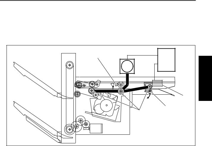
3.1Conveyance/Paper exit section
OUTLINE |
[6] |
|
|
[7] |
|
I |
|
|
|
[5] |
|
|
[4] |
[8] |
|
[3] |
|
|
[2] |
[1] |
[1] Paper jam release knob |
[5] M702 |
(Paper exit motor) |
||
[2] |
Conveyance belt |
[6] |
M701 |
(Conveyance motor) |
[3] Paper exit roller /A |
[7] |
Conveyance roller |
||
[4] |
Clutch |
[8] |
Pressure roller |
|
1-6
DRIVE SYSTEM DIAGRAM
3.2Alignment section
[3]
[4]
[5]
[2]
|
|
|
[1] |
|
|
|
|
|
|
[1] |
M704 |
(Alignment motor /F) |
[4] |
Rear stopper |
[2] |
M703 |
(Alignment motor /R) |
[5] |
Alignment plate /F |
[3]Alignment plate /R
3.3Stapler section
[2]
[3]
[1]
I OUTLINE
[1] |
M705 (Stapler movement motor) |
[3] M708 (Stapler motor) |
[2] |
Stapler |
|
1-7
DRIVE SYSTEM DIAGRAM
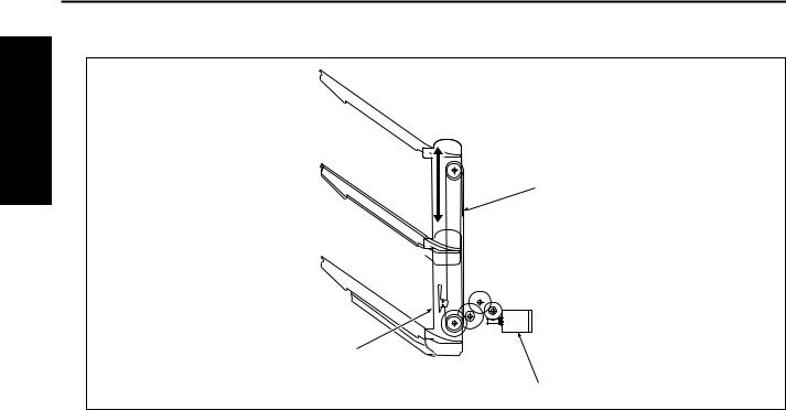
3.4Tray section
I OUTLINE
[1]
[3]
[2]
[1] Up/down wire |
[3] Tray unit |
[2]M706 (Tray up/down motor)
1-8
CONVEYANCE SECTION
II UNIT EXPLANATION
1. CONVEYANCE SECTION
1.1Composition
[4]
FS CB
M701
[1]
[2]
[3]
II UNIT EXPLANATION
Symbol |
Name |
Function or method |
|
|
|
[1] |
SD701 (Roller release solenoid) |
Control of the pressure/release of the conveyance pressure |
|
|
roller according to the line speed and paper size |
|
|
While in operation, paper pressure by the conveyance pres- |
|
|
sure roller is released. |
|
|
|
[2] |
Conveyance pressure roller |
Transmission/transmission release of conveyance force of the |
|
|
conveyance roller to the paper |
|
|
|
[3] |
Conveyance roller |
Paper conveyance |
|
|
|
[4] |
PS702 (FNS entrance sensor) |
Detection of paper conveyed |
|
|
|
M701 |
FNS conveyance motor |
Driving of the conveyance roller |
|
|
Variable control speed method by 24VDC stepping motor |
|
|
drive |
|
|
|
2-1
II UNIT EXPLANATION
CONVEYANCE SECTION
1.2Operation
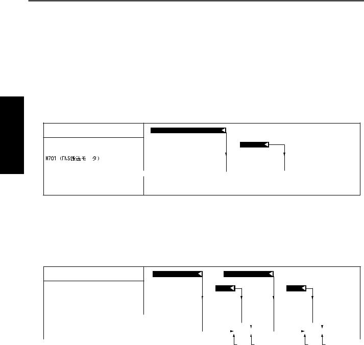
1.2.1Conveyance control
Conveyance controls can be roughly divided into the following 2 patterns:
A. Pattern 1: Normal conveyance control
•While the paper is nipped to both the main body’s fixing roller and the FNS conveyance roller, the M701 (FNS conveyance motor) operates at the speed of 230 mm/s according to the main body line speed. When the paper passes through the fixing roller, the M701 operates at the speed of 600 mm/s.
PS2 (Main body’s fixing exit sensor)
PS702 (FNS entrance sensor)
|
|
|
600mm/s/s |
|
|
|
|
M701 |
|
|
|
||
|
(FNS conveyance motor) |
|
|
|
|
|
|
|
230mm/sm /s |
|
|
|
|
|
|
|
||||
|
|
|
|
|
|
|
SD701 (Roller release solenoid)
B. Pattern 2: Conveyance control of small-sized paper with paper intervals narrower
•While the paper is nipped to both the main body’s fixing roller and the FNS conveyance roller, the SD701 (Roller release solenoid) is turned on to release the nip of the FNS conveyance roller for the increased productivity of sorting, grouping and stapling.
PS2 (Main body’s fixing exit sensor)
PS702 (FNS entrance sensor)
|
|
|
|
|
|
|
|
|
|
|
|
|
|
|
|
|
|
M701 |
600mm/s |
|
|
|
|
|
|
|
|
|
|
||||
|
|
|
|
|
|
|
|
|
|
|||||||
|
(FNS conveyance motor) |
|
|
|
|
|
|
|
|
|
|
|
|
|
|
|
|
|
|
|
|
|
|
|
|
|
|
|
|
|
|
|
|
|
|
|
|
|
|
|
|
|
|
|
|
|
|
|||
|
|
230mm/s |
|
|
|
|
|
|
|
|
|
|
|
|||
|
|
|
|
|
|
|
|
|
|
|
|
|
|
|
|
|
|
|
|
|
|
|
|
|
|
|
|
|
|
|
|||
|
|
|
|
|
|
|
|
|
|
|
||||||
|
SD701 (Roller release solenoid) |
|
|
|
|
|
|
|
|
|
|
|
||||
|
|
|
|
|
|
|
|
|
|
|
||||||
|
|
|
|
|
|
|
|
|
|
|
|
|
|
|
|
|
|
|
|
|
|
|
|
|
|
|
|
|
|
|
|
|
|
|
|
|
|
|
|
|
[1] [2] |
[3] [4] |
||||||||
|
[1] Release of the pressure roller for the 1st |
[3] Release of the pressure roller for the 2nd |
||||||||||||||
|
paper |
|
|
|
|
paper |
|
|
|
|
|
|||||
|
[2] Pressuring of the pressure roller for the 1st |
[4] Pressuring of the pressure roller for the |
||||||||||||||
|
paper |
|
|
|
|
2nd paper |
|
|
|
|
|
|||||
2-2
PAPER EXIT SECTION
2. PAPER EXIT SECTION
2.1Composition
|
|
[10] |
|
[6] |
[7] |
[8] |
[9] |
[5] |
|
|
EXPLANATION |
[4] |
|
|
UNITII |
|
|
FNS CB |
|
[3] |
|
|
|
|
[2] |
[1] |
|
|
|
|
|
|
Symbol |
Name |
Function or method |
|
|
|
[1] |
M707 (Pressure motor) |
Driving of the pressure cam (when in forward rotation), Driving of |
|
|
the shutter cam (when in backward rotation) |
|
|
Driving of 24VDC DC brush motor |
|
|
|
[2] |
MS702 (Shutter switch) |
Detection of abnormal release of the shutter while the tray is |
|
|
going up and down |
|
|
|
[3] |
Shutter cam |
Converting the rotational motion of the pressure motor into the |
|
|
open/close motion of the shutter |
|
|
|
[4] |
PS705 (Shutter sensor) |
HP detection of the shutter |
|
|
|
[5] |
PS701 (Pressure sensor) |
Detection of pressure/release of the paper exit roller /A |
|
|
|
[6] |
Shutter |
To prevent accidents (getting a finger caught, etc.), the paper exit |
|
|
opening is closed while the tray is going up or down. |
|
|
The paper exit opening is closed by the backward rotation of the |
|
|
M707 (Pressure motor). |
|
|
|
[7] |
Paper exit roller /A |
Paper exit to the tray, conveyance of paper to the stack section |
|
|
when in the offset mode or staple mode |
|
|
Torque limiter pressure method |
|
|
|
[8] |
Pressure cam |
Converting the rotational motion of the pressure motor into the |
|
|
pressure/release motion of the paper exit roller /A |
|
|
|
[9] |
M702 (Paper exit motor) |
Driving of the paper exit roller and the paper exit roller /A |
|
|
When in forward rotation: Paper exit to the tray |
|
|
When in backward rotation: Conveyance to the stack section |
|
|
|
2-3
II UNIT EXPLANATION
PAPER EXIT SECTION
Symbol |
Name |
Function or method |
|
|
|
[10] |
Clutch |
Transmission/release of driving force from the M702 (Paper exit |
|
|
motor) to the paper exit roller |
|
|
|
2.2Operation
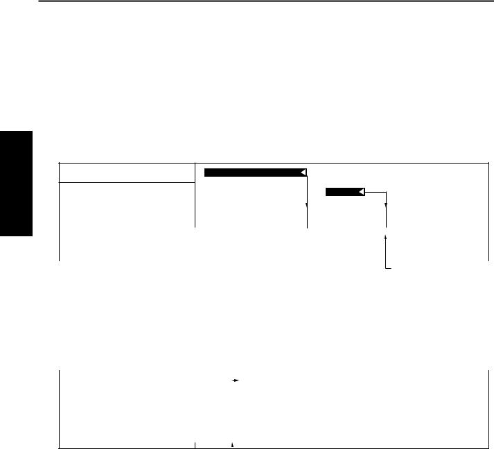
2.2.1Paper exit control
A. Straight paper exit
PS2 (Main body’s fixing exit sensor)
PS702 (FNS entrance sensor)
|
|
|
|
|
|
|
|
|
|
|
|
|
|
M702 |
F |
600mm/s |
|
|
|
|
|||||
|
(Paper exit motor) |
|
|
|
|
|
|
|
|
|
|
|
|
|
|
|
|
|
|
|
|
|
|
|
|
|
|
|
|
|
|
|
|
|
|
|||
|
|
|
|
|
|
230mm/s |
|
|
|
|
|
|
|
|
|
|
|
|
|
|
|
|
|
|
|
|
|
|
|
|
|
|
|
|
|
|
|
|
|
|
|
|
|
|
|
|
|
|
|||
|
|
|
|
R |
|
|
|
|
||||
|
|
|
|
|
|
|
|
|
|
|
|
|
[1]
[1]Decelerated paper exit
B. Paper exit after stacking
(1) Staple paper exit
|
|
|
|
|
|
|
|
|
|
|
|
|
M702 |
|
F |
600mm/s |
|
|
|
|
|||||
|
|
|
|
|||||||||
|
(Paper exit motor) |
|
|
|
|
|
|
|
|
|
|
|
|
|
|
|
|
|
|
|
|
|
|
|
|
|
|
|
|
|
|
|
|
|
|
|||
|
|
|
230mm/s |
|
|
|
|
|
|
|||
|
|
|
|
|
|
|
|
|
|
|
|
|
|
|
|
|
|
|
|
|
|
|
|
|
|
|
|
|
|
|
|
|
|
|
|
|||
|
|
|
|
R |
|
|
|
|
||||
|
|
|
|
|
|
|
|
|
|
|
|
|
|
M708 (Stapler motor) |
|
|
|
|
|
|
|
|
|
|
|
|
|
|
|
|
|
|
|
|
|
|||
|
|
|
|
|
|
|
|
|
|
|||
 [1]
[1]
[1]Stapling completed and starting of paper exit
2-4
PAPER EXIT SECTION
(2) Shift control
[3]
|
|
|
|
|
|
|
|
|
|
|
|
|
|
|
|
|
|
|
|
|
|
|
|
|
|
|
|
M702 |
|
F |
600mm/s |
|
|
|
|
|
|
|
|
|
|
|
|
|
|
|
|
|
|||||
|
|
|
|
|
|
|
|
|
|
|
|
|
|
|
|
|
|
|||||||||
|
(Paper exit motor) |
|
|
|
|
|
|
|
|
|
|
|
|
|
|
|
|
|
|
|
|
|
|
|
|
|
|
|
|
|
|
|
|
|
|
|
|
|
|
|
|
|
|
|
|
|
|
|
|
|
|||
|
|
|
|
|
|
230mm/s |
|
|
|
|
|
|
|
|
|
|
|
|
|
|
|
|
|
|
||
|
|
|
|
|
|
|
|
|
|
|
|
|
|
|
|
|
|
|
|
|
|
|
|
|
||
|
|
|
|
|
|
|
|
|
|
|
|
|
|
|
|
|
|
|
|
|
|
|
|
|
|
|
|
|
|
|
|
|
|
|
|
|
|
|
|
|
|
|
|
|
|
|
|
|
|
|
|
|
|
|
|
|
|
|
|
|
|
|
|
|
|
|
|
|
|
|
|
|
|
|
|
|
|
|
|
|
|
|
|
|
|
|
|
|
|
|
|
|
|
|
|
|
|
|
|
|
|
|
|
||||
|
|
|
|
R |
|
|
|
|
|
|
|
|
|
|
|
|
|
|
|
|
|
|||||
|
|
|
|
|
|
|
|
|
|
|
|
|
|
|
|
|||||||||||
|
|
|
|
|
|
|
|
|
|
|
|
|
|
|
|
|
|
|
|
|
|
|
|
|
|
|
|
|
|
|
|
|
|
|
|
|
|
|
|
|
|
|
|
|
|
|
|
|
|
|
|
|
|
|
|
|
|
|
|
|
|
|
|
|
|
|
|
|
|
|
|
|
|
|
|
|
|
|
|
|
|
|
|
|
|
|
|
|
|
|
|
|
|
|
|
|
|
|
|
|
|
|
|
||||
|
|
|
|
|
|
|
|
|
|
|
|
|
|
|
|
|
|
|||||||||
|
M703 |
|
Alignment/Shift |
|
|
|
|
|
|
|
|
|
|
|
|
|
|
|
|
|
||||||
|
(Alignment motor /R) |
|
|
|
|
|
|
|
|
|
|
|
|
|
|
|
|
|
|
|
|
|
|
|
|
|
|
|
|
|
|
|
|
|
|
|
|
|
|
|
|
|
|
|
|
|
|
|
|
|
|
|
|
|
|
|
|
|
|
|
|
|
|
|
|
|
|
|
|
|
|
|
|
|
|
|
|
|||
|
|
|
|
Open |
|
|
|
|
|
|
|
|
|
|
|
|
|
|
|
|
|
|
||||
|
|
|
|
|
|
|
|
|
|
|
|
|
|
|
|
|
|
|
|
|
|
|
|
|
|
|
|
|
|
|
|
|
|
|
|
|
|
|
|
|
|
|
|
|
|
|
|
|
|
|
|
|
|
|
|
|
|
|
|
|
|
|
|
|
|
|
|
|
|
|
|
|
|
|
|
|
||||
|
M704 |
|
Alignment |
|
|
|
|
|
|
|
|
|
|
|
|
|
|
|
|
|
||||||
|
(Alignment motor /F) |
|
|
|
|
|
|
|
|
|
|
|
|
|
|
|
|
|
|
|
|
|
|
|
|
|
|
|
|
|
|
|
|
|
|
|
|
|
|
|
|
|
|
|
|
|
|
|
|
|
|
|
|
|
|
|
|
|
|
|
|
|
|
|
|
|
|
|
|
|
|
|
|
|
|
|
|
|||
|
|
|
Shift/Open |
|
|
|
|
|
|
|
|
|
|
|
|
|
|
|
|
|
|
|
||||
|
|
|
|
|
|
|
|
|
|
|
|
|
|
|
|
|
|
|
|
|
|
|||||
|
|
|
|
|
|
|
|
|
|
|
|
|
|
|
|
|
|
|
|
|
|
|
|
|
|
|
|
|
|
|
|
|
|
|
|
|
|
|
|
|
|
|
|
|
|
|
|
|
|
|
|
|
|
|
|
|
|
|
|
|
|
|
|
|
|
|
|
|
|
|
|
|
|
|
|
|
||||
|
|
|
|
|
|
|
|
|
|
|
|
|
|
|
|
|
|
|||||||||
|
M707 |
|
Pressure |
|
|
|
|
|
|
|
|
|
|
|
|
|
|
|
|
|
||||||
|
|
|
|
|
|
|
|
|
|
|
|
|
|
|
|
|
|
|||||||||
|
(Pressure motor) |
|
|
|
|
|
|
|
|
|
|
|
|
|
|
|
|
|
|
|
|
|
|
|
|
|
|
|
|
|
|
|
|
|
|
|
|
|
|
|
|
|
|
|
|
|
|
|
|
|
|
|
|
|
|
|
|
|
|
|
|
|
|
|
|
|
|
|
|
|
|
|
|
|
|
|
|
|||
|
|
|
|
Release |
|
|
|
|
|
|
|
|
|
|
|
|
|
|
|
|
|
|
||||
|
|
|
|
|
|
|
|
|
|
|
|
|
|
|
|
|
|
|
|
|
||||||
|
|
|
|
|
|
|
|
|
|
|
|
|
|
|
|
|
|
|
|
|
|
|
|
|
|
|
|
|
|
|
|
|
|
|
|
|
|
|
|
|
|
|
|
|
|
|
|
|
|
|
|
|
|
|
|
|
|
|
|
|
|
|
|
|
|
|
|
|
|
|
|
|
|
|
|
|
|
|
|
|
|
|
|
|
[1] [2] [4] |
[5] |
|
|
|
|
|
|
|
||||||||||||||
|
[1] Conveying the last paper of the set to the |
|
|
|
[3] Clutch locked |
|||||||||||||||||||||
|
stack section |
|
|
|
|
|
|
|
|
|
|
|
|
|
|
|
|
[4] Pressuring of the paper exit roller /A |
||||||||
|
[2] Clutch released |
|
|
|
|
|
|
|
|
|
|
|
|
|
|
|
|
[5] Starting of paper exit |
||||||||
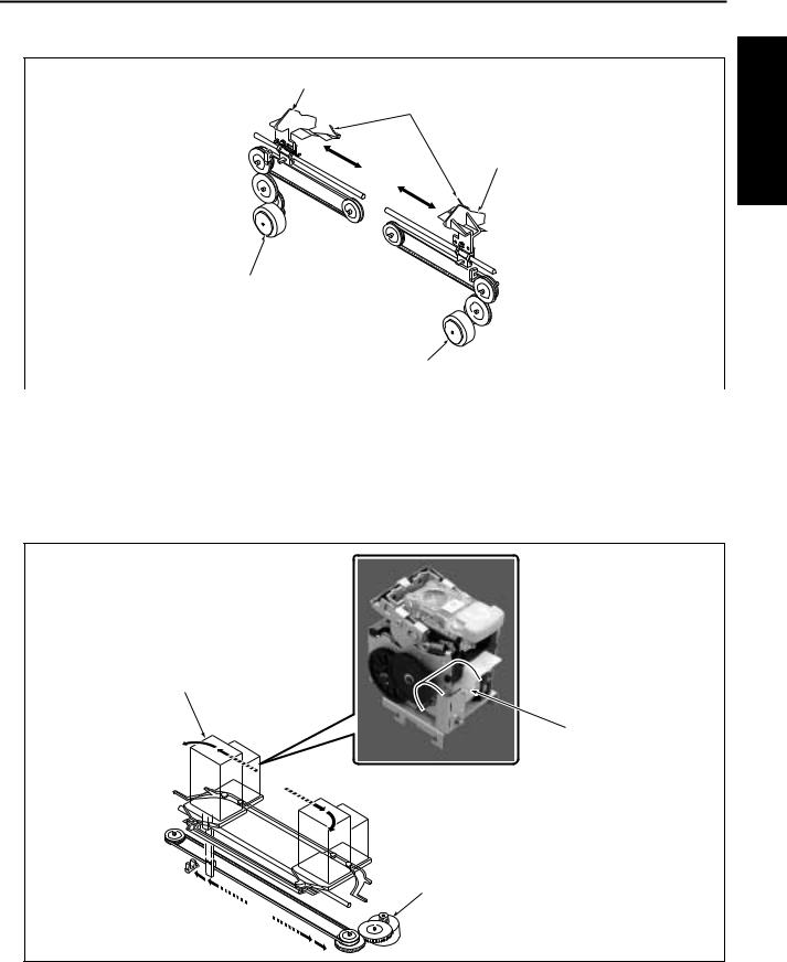
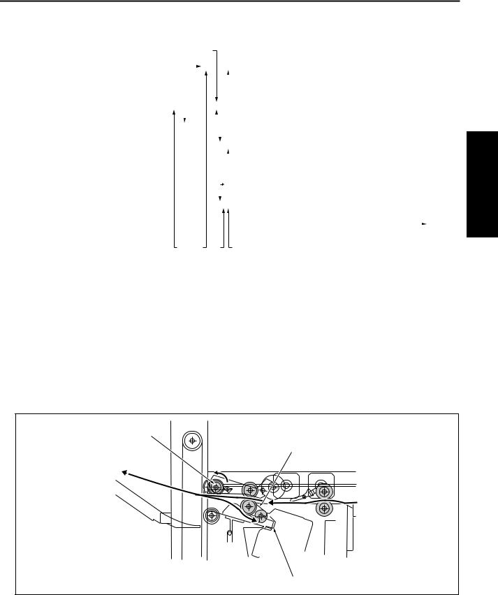
2.2.2Paper stack control
While in the sort mode, group mode or staple mode, paper conveyed to the paper exit opening is conveyed to the stack section by the backward rotation of the paper exit roller /A [1]. The paper thus conveyed is sent up to the stopper [3] by the frictional force of the conveyance belt [2] to be stacked.
[1]
[2]
[3]
II UNIT EXPLANATION
2-5
II UNIT EXPLANATION
PAPER EXIT SECTION
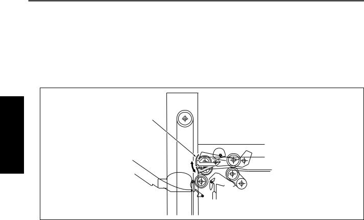
2.2.3Shutter control
While the tray is going up or down, the shutter [1] is driven by the backward rotation of the M707 (Pressure motor) to close the paper exit opening. This is to prevent accidents such as the hand being caught in the paper exit opening.
If the shutter opens while the tray is going up or down, the MS702 (Shutter switch) is turned on to shut off the power of 24VDC and the FNS is immediately stopped.
[1]
2-6
ALIGNMENT SECTION
3. ALIGNMENT SECTION
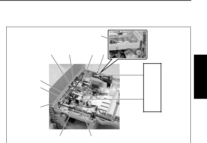
3.1Composition
[6] |
[7] |
[8] |
[5] |
|
|
|
|
FNS CB |
[4] |
|
|
|
[3] |
|
|
|
[2] |
|
|
[1] |
Symbol |
Name |
Function or method |
|
|
|
[1] |
M704 (Alignment motor /F) |
Driving of the alignment plate /F |
|
|
24VDC stepping motor drive |
|
|
|
[2] |
PS710 (Alignment HP sensor /F) |
HP detection of the alignment plate /F |
|
|
|
[3] |
Alignment plate /F |
Paper alignment in front of the stack section |
|
|
|
[4] |
M703 (Alignment motor /R) |
Driving of the alignment plate /R |
|
|
24VDC stepping motor drive |
|
|
|
[5] |
PS709 (Alignment HP sensor /R) |
HP detection of the alignment plate /R |
|
|
|
[6] |
Alignment plate /R |
Paper alignment in rear of the stack section |
|
|
|
[7] |
Rear stopper |
Alignment of the rear end of paper in the stack section, |
|
|
when in the sort, group, and staple mode |
|
|
|
[8] |
PS707 (No paper sensor) |
No paper detection in the stack section |
|
|
|
II UNIT EXPLANATION
2-7

II UNIT EXPLANATION
ALIGNMENT SECTION
3.2Operation
3.2.1Paper alignment control
Paper stacked by the paper exit roller /A is aligned by the alignment plates. The alignment plates provided in front and rear, one for each, are driven independently by the M704 (Alignment motor /F) and the M703 (Alignment motor /R). For straight alignment of the sorting, grouping, and stapling operation, the paper moves symmetrically in front and in rear, and is aligned at the center by the alignment plates and it moves asymmetrically while in the shift mode.
The home positions of the alignment plates are detected by the PS709 (Alignment HP sensor /R) and the PS710 (Alignment HP sensor /F).
A.Straight alignment operation
Small size paper such as 5.5 x 8.5R, A5R or B5R is stacked and aligned to prevent the paper from having uneven edge after being exited.
During the paper exit, the alignment plate /F and the alignment plate /R move symmetrically in front and in rear based on the center of the alignment section with alternations of alignment and alignment release. Aligned papers are exited for every 5 sheets.
|
|
|
|
|
[2] |
|
|
|
[4] |
|
|
|
|
|
[6] |
|
[4] |
|
|
|
||||||||||||||||
|
|
|
|
|
|
|
|
|
|
|
|
|
|
|
|
|
|
|
|
|
|
|
|
|
|
|
|
|
|
|
|
|
|
|
|
|
|
|
|
|
|
|
|
|
|
|
|
|
|
|
|
|
|
|
|
|
|
|
|
|
|
|
|
|
|
|
|||||||
|
PS2 (Main body’s fixing exit sensor) |
|
|
|
|
|
|
|
|
|
|
|
|
|
|
|
|
|
|
|
|
|
|
|
|
|||||||||||
|
|
|
|
|
|
|
|
|
|
|
|
|
|
|
|
|
|
|
|
|
|
|
|
|||||||||||||
|
|
|
|
|
|
|
|
|
|
|
|
|
|
|
|
|
|
|
|
|
|
|
|
|
|
|
|
|
|
|
|
|
|
|
|
|
|
|
|
|
|
|
|
|
|
|
|
|
|
|
|
|
|
|
|
|
|
|
|
|
|
|
|
|
|
|
|
|
|
|
|
|
|
|
|
|
|
|
|
|
|
|
|
|
|
|
|
|
|
|
|
|
|
|
|
|
|
|
|
|
|
|
||||||||
|
PS702 (FNS entrance sensor) |
|
|
|
|
|
|
|
|
|
|
|
|
|
|
|
|
|
|
|
|
|
|
|
|
|||||||||||
|
|
|
|
|
|
|
|
|
|
|
|
|
|
|
|
|
|
|
|
|
|
|
|
|||||||||||||
|
|
|
|
|
|
|
|
|
|
|
|
|
|
|
|
|
|
|
|
|
|
|
|
|||||||||||||
|
|
|
|
|
|
|
|
|
|
|
|
|
|
|
|
|
|
|
|
|
|
|
|
|
|
|
|
|
|
|
|
|
|
|
|
|
|
|
|
|
|
|
|
|
|
|
|
|
|
|
|
|
|
|
|
|
|
|
|
|
|
|
|
|
|
|
|
|
|
|
|
|
|
|
|
|
|
|
|
|
|
|
|
|
|
|
|
|
|
|
|
|
|
|
|
|
|
|
|
|
|
|
|
|
|
|
|
|
|
|
|
M702 |
F |
600mm/s |
|
|
|
|
|
|
|
|
|
|
|
|
|
|
|
|
|
|
|
|
|
|
|
|
|||||||||
|
|
|
|
|
|
|
|
|
|
|
|
|
|
|
|
|
|
|
|
|
|
|
|
|||||||||||||
|
(Paper exit motor) |
|
|
|
|
|
|
|
|
|
|
|
|
|
|
|
|
|
|
|
|
|
|
|
|
|
|
|
|
|
|
|
|
|
|
|
|
|
|
|
|
|
|
|
|
|
|
|
|
|
|
|
|
|
|
|
|
|
|
|
|
|
|
|
|
|
|
|
|
|
|
||
|
|
|
|
|
|
|
|
|
|
|
|
|
|
|
|
|
|
|
|
|
|
|
|
|
|
|
|
|
|
|
|
|||||
|
|
|
|
|
|
|
|
|
230mm/s |
|
|
|
|
|
|
|
|
|
|
|
|
|
|
|
|
|
|
|
|
|
|
|
|
|
|
|
|
|
|
|
|
|
|
|
|
|
|
|
|
|
|
|
|
|
|
|
|
|
|
|
|
|
|
|
|
|
|
|
|||||
|
|
|
|
|
|
|
|
|
|
|
|
|
|
|
|
|
|
|
|
|
|
|
|
|
|
|
|
|
|
|
|
|
|
|
|
|
|
|
|
|
|
|
|
|
|
|
|
|
|
|
|
|
|
|
|
|
|
|
|
|
|
|
|
|
|
|
|
|
|
|
|
|
|
|
|
|
|
|
|
|
|
|
|
|
|
|
|
|
|
|
|
|
|
|
|
|
|
|
|
|
|
|
|
|
||||||
|
|
|
|
|
|
R |
|
|
|
|
|
|
|
|
|
|
|
|
|
|
|
|
|
|
|
|
|
|
|
|
||||||
|
|
|
|
|
|
|
|
|
|
|
|
|
|
|
|
|
|
|
|
|
|
|
|
|
|
|
|
|
|
|
|
|
|
|
|
|
|
|
|
|
|
|
|
|
|
|
|
|
|
|
|
|
|
|
|
|
|
|
|
|
|
|
|
|
|
|
|
|
|
|
|
|
|
|
|
|
|
|
|
|
|
|
|
|
|
|
|
|
|
|
|
|
|
|
|
|
|
|
|
|
|
|
|
|||||||
|
M703 |
|
Alignment/Shift |
|
|
|
|
|
|
|
|
|
|
|
|
|
|
|
|
|
|
|
|
|
|
|
|
|||||||||
|
(Alignment motor /R) |
|
|
|
|
|
|
|
|
|
|
|
|
|
|
|
|
|
|
|
|
|
|
|
|
|
|
|
|
|
|
|
|
|
||
|
|
|
|
|
|
|
|
|
|
|
|
|
|
|
|
|
|
|
|
|
|
|
|
|
|
|
|
|
|
|
|
|
|
|||
|
|
|
|
|
|
|
|
|
|
|
|
|
|
|
|
|
|
|
|
|
|
|
|
|
|
|||||||||||
|
|
|
Open |
|
|
|
|
|
|
|
|
|
|
|
|
|
|
|
|
|
|
|
|
|
|
|
|
|||||||||
|
|
|
|
|
|
|
|
|
|
|
|
|
|
|
|
|
|
|
|
|
|
|
|
|||||||||||||
|
|
|
|
|
|
|
|
|
|
|
|
|
|
|
|
|
|
|
|
|
|
|
|
|
|
|
|
|
|
|
|
|
|
|
|
|
|
|
|
|
|
|
|
|
|
|
|
|
|
|
|
|
|
|
|
|
|
|
|
|
|
|
|
|
|
|
|
|
|
|
|
|
|
|
|
|
|
|
|
|
|
|
|
|
|
|
|
|
|
|
|
|
|
|
|
|
|
|
|
|
|
|
|
|
|
|
|
|
|
|
|
|
|
|
|
|
|
|
|
|
|
|
|
|
|
|
|
|
|
|
|
|
|
|
|
|
|
|
|
||||||||
|
M704 |
|
Alignment |
|
|
|
|
|
|
|
|
|
|
|
|
|
|
|
|
|
|
|
|
|
|
|
|
|||||||||
|
|
|
|
|
|
|
|
|
|
|
|
|
|
|
|
|
|
|
|
|
|
|
|
|||||||||||||
|
(Alignment motor /F) |
|
|
|
|
|
|
|
|
|
|
|
|
|
|
|
|
|
|
|
|
|
|
|
|
|
|
|
|
|
|
|
|
|
||
|
|
|
|
|
|
|
|
|
|
|
|
|
|
|
|
|
|
|
|
|
|
|
|
|
|
|
|
|
|
|
|
|
|
|||
|
|
|
|
|
|
|
|
|
|
|
|
|
|
|
|
|
|
|
|
|
|
|
|
|
|
|||||||||||
|
|
|
Shift/Open |
|
|
|
|
|
|
|
|
|
|
|
|
|
|
|
|
|
|
|
|
|
|
|
|
|||||||||
|
|
|
|
|
|
|
|
|
|
|
|
|
|
|
|
|
|
|
|
|
|
|
|
|||||||||||||
|
|
|
|
|
|
|
|
|
|
|
|
|
|
|
|
|
|
|
|
|
|
|
|
|
|
|
|
|
|
|||||||
|
|
|
|
|
|
|
|
|
|
|
|
|
|
|
|
|
|
|
|
|
|
|
|
|
|
|
|
|
|
|
|
|
|
|
|
|
|
|
|
|
|
|
|
|
|
|
|
|
|
|
|
|
|
|
|
|
|
|
|
|
|
|
|
|
|
|
|
|
|
|
|
|
|
|
|
|
|
|
|
|
|
|
|
|
|
|
|
|
|
|
|
|
|
|
|
|
|
|
|
|
|
|
||||||||
|
M707 |
|
Pressure |
|
|
|
|
|
|
|
|
|
|
|
|
|
|
|
|
|
|
|
|
|
|
|
|
|||||||||
|
(Pressure motor) |
|
|
|
|
|
|
|
|
|
|
|
|
|
|
|
|
|
|
|
|
|
|
|
|
|
|
|
|
|
|
|
|
|
||
|
|
|
|
|
|
|
|
|
|
|
|
|
|
|
|
|
|
|
|
|
|
|
|
|
|
|
|
|
|
|
|
|||||
|
|
|
|
|
Release |
|
|
|
|
|
|
|
|
|
|
|
|
|
|
|
|
|
|
|
|
|
|
|
|
|||||||
|
|
|
|
|
|
|
|
|
|
|
|
|
|
|
|
|
|
|
|
|
|
|
|
|
|
|
|
|
|
|||||||
|
|
|
|
|
|
|
|
|
|
|
|
|
|
|
|
|
|
|
|
|
|
|
|
|
|
|
|
|
|
|
|
|
|
|
|
|
|
|
|
|
|
|
|
|
|
|
|
|
|
|
|
|
|
|
|
|
|
|
|
|
|
|
|
|
|
|
|
|
|
|
|
|
|
|
|
|
|
|
[1] |
|
|
[3] |
|
[5] |
[7] |
[8] |
[9] |
|
|
|||||||||||||||||||||
|
[1] The 1st paper passes through the FNS |
|
|
|
|
|
[5] Alignment operation of the 1st paper |
|||||||||||||||||||||||||||||
|
conveyance section. |
|
|
|
|
|
[6] The 3rd paper is exited from the main |
|||||||||||||||||||||||||||||
|
[2] The 2nd paper is exited from the main |
|
|
|
|
|
|
|
body. |
|
|
|
|
|
|
|
|
|
||||||||||||||||||
|
body. |
|
|
|
|
|
|
|
|
|
|
|
|
|
|
|
|
|
[7] The 2nd paper turns off the FNS |
|||||||||||||||||
|
[3] The 1st paper is conveyed to the stack |
|
|
|
|
|
|
|
entrance sensor. |
|
|
|
|
|
|
|||||||||||||||||||||
|
section. |
|
|
|
|
|
|
|
|
|
|
|
|
|
|
|
|
|
[8] The 2nd paper is conveyed to the stack |
|||||||||||||||||
|
[4] The paper exit roller /A goes up to prepare |
|
|
|
|
section. |
|
|
|
|
|
|
|
|
|
|||||||||||||||||||||
|
the conveyance path for the next paper. |
|
|
[9] Alignment operation of the 2nd paper |
||||||||||||||||||||||||||||||||
2-8
Loading...