


 Loading...
SERVICE MANUAL
Model
FS-107
SECOND EDITION
NOVEMBER 2000
CSM-FS107
KONICA BUSINESS TECHNOLOGIES, INC.

FS-107
SERVICE MANUAL
NOVEMBER 2000
SECOND EDITION

IMPORTANT NOTICE
Because of the possible hazards to an inexperienced person servicing this equipment, as well as the risk of damage to the equipment, Konica Business Technologies strongly recommends that all servicing be performed by Konica-trained service technicians only.
Changes may have been made to this equipment to improve its performance after this service manual was printed. Accordingly, Konica Business Technologies, Inc., makes no representations or warranties, either expressed or implied, that the information contained in this service manual is complete or accurate. It is understood that the user of this manual must assume all risks or personal injury and/or damage to the equipment while servicing the equipment for which this service manual is intended.
Corporate Publications Department
© 2000, KONICA BUSINESS TECHNOLOGIES, INC. All rights reserved.
Printed in U.S.A.

FS-107
CONTENTS |
|
OUTLINE |
|
PRODUCT SPECIFICATIONS ......................................... |
1 |
Type .......................................................................... |
1 |
Functions .................................................................. |
1 |
Stapler kit .................................................................. |
2 |
Machine data ............................................................ |
2 |
Maintenance ............................................................. |
2 |
Machine environment ............................................... |
2 |
CENTRAL CROSS SECTION .......................................... |
3 |
DRIVE SYSTEM DIAGRAM ............................................. |
4 |
Paper conveyance drive ........................................... |
4 |
Stapler unit drive ....................................................... |
5 |
PAPER CONVEYANCE PATH ......................................... |
6 |
Straight mode ............................................................ |
6 |
Offset mode/staple mode .......................................... |
7 |
UNIT EXPLANATION |
|
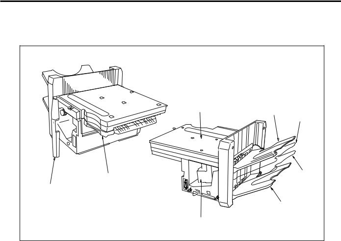
EXTERNAL SECTION ..................................................... |
9 |
Composition .............................................................. |
9 |
CONVEYANCE SECTION ............................................. |
10 |
Composition ............................................................ |
10 |
Mechanisms ............................................................ |
10 |
Conveyance control ................................................ |
11 |
Tray up/down control .............................................. |
13 |
PAPER EXIT/STAPLER UNIT ....................................... |
15 |
Composition ............................................................ |
15 |
Mechanisms ............................................................ |
15 |
Paper alignment control .......................................... |
17 |
Paper exit control .................................................... |
18 |
Paper stack control ................................................. |
19 |
Stapler control ......................................................... |
20 |
Staple control .......................................................... |
21 |
OTHER KINDS OF CONTROL ...................................... |
23 |
Movement with power on ........................................ |
23 |
Opening and closing motion of the |
|
front door ............................................................... |
23 |
DISASSEMBLY/ASSEMBLY |
|
DISASSEMBLY/ASSEMBLY ........................................... |
25 |
Removing and reinstalling of the finisher .............. |
25 |
Removing and reinstalling of the tray .................... |
25 |
Replacing the paper exit roller/A ............................ |
26 |
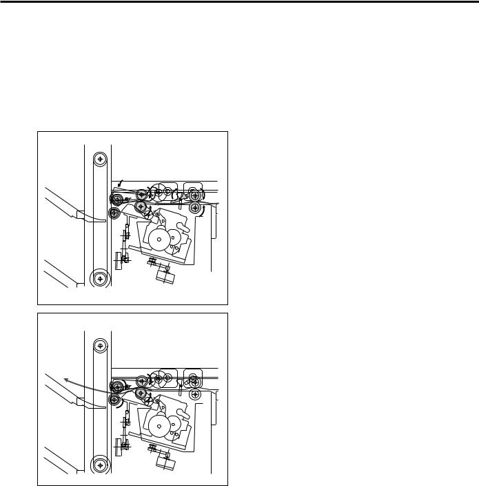
Removing and reinstalling of the up/down wire .... |
28 |
Replacing the stapler cartridge .............................. |
29 |
Removing and reinstalling the stapler unit .......... |
30 |
DIAGRAMS |
|
ELECTRICAL PARTS LAYOUT ..................................... |
31 |
CONNECTOR LAYOUT ................................................. |
33 |
TIME CHART (8.5X11, SORT MODE, 2 SHEETS/SET |
|
2 SETS) ........................................................................ |
35 |
TIME CHART (8.5X11, STAPLE MODE 2 SHEETS, |
|
1 POSITION ................................................................. |
36 |
OVERALL WIRING DIAGRAM ....................................... |
37 |
iii

FS-107
This page left blank intentionally.
iv

SAFETY PRECAUTIONS
SAFETY PRECAUTIONS
Installation Environment
Safety considerations usually are directed toward machine design and the possibility of human error. In addition, the environment in which a machine is operated must not be overlooked as a potential safety hazard.
Most electrical equipment is safe when installed in a normal environment. However, if the environment is different from what most people consider to be normal, it is conceivable that the combination of the machine and the room air could present a hazardous combination. This is because heat (such as from fusing units) and electrical arcs (which can occur inside switches) have the ability to ignite flammable substances, including air.
When installing a machine, check to see if there is anything nearby which suggests that a potential hazard might exist. For example, a laboratory might use organic compounds which, when they evaporate, make the room air volatile. Potentially dangerous conditions might be seen or smelled. The presence of substances such as cleaners, paint thinners, gasoline, alcohol, solvents, explosives, or similar items should be cause for concern.
If conditions such as these exist, take appropriate action, such as one of the following suggestions.
∙Determine that the environment is controlled (such as through the use of an exhaust hood) so that an offending substance or its fumes cannot reach the machine.
∙Remove the offending substance.
∙Install the machine in a different location.
The specific remedy will vary from site to site, but the principles remain the same. To avoid the risk of injury or damage, be alert for changes in the environment when performing subsequent service on any machine, and take appropriate action.
Unauthorized Modifications
Konica copiers have gained a reputation for being reliable products. This has been attained by a combination of outstanding design and a knowledgeable service force.
The design of the copier is extremely important. It is the design process that determines tolerances and safety margins for mechanical, electrical, and electronic aspects. It is not reasonable to expect individuals not involved in product engineering to know what
effect may be caused by altering any aspect of the machine’s design. Such changes have the potential of degrading product performance and reducing safety margins.
For these reasons, installation of any modification not specifically authorized by Konica Business Machines U.S.A., Inc., is strictly prohibited.
The following list of prohibited actions is not all-inclu- sive, but demonstrates the intent of this policy.
∙Using an extension cord or any unauthorized power cord adapter.
∙Installing any fuse whose rating and physical size differs from that originally installed.
∙Using wire, paper clips, solder, etc., to replace or eliminate any fuse (including temperature fuses).
∙Removing (except for replacement) any air filter.
∙Defeating the operation of relays by any means (such as wedging paper between contacts).
∙Causing the machine to operate in a fashion other than as it was designed.
∙Making any change which might have a chance of defeating built-in safety features.
∙Using any unspecified replacement parts.
General Safety Guidelines
This copier has been examined in accordance with the laws pertaining to various product safety regulations prior to leaving the manufacturing facility to protect the operators and service personnel from injury. However, as with any operating device, components will break down through the wear-and-tear of everyday use, as will additional safety discrepancies be discovered. For this reason, it is important that the technician periodically performs safety checks on the copier to maintain optimum reliability and safety.
The following checks, not all-inclusive, should be made during each service call:
CAUTION: Avoid injury. Ensure that the copier is disconnected from its power source before continuing.
∙Look for sharp edges, burrs, and damage on all external covers and copier frame.
∙Inspect all cover hinges for wear (loose or broken).
∙Inspect cables for wear, frays, or pinched areas.
v

SAFETY PRECAUTIONS
∙Ensure that the power cord insulation is not damaged (no exposed electrical conductors).
∙Ensure that the power cord is properly mounted to the frame by cord clamps.
∙Check the continuity from the round lug (GND) of the power cord to the frame of the copier -- ensure continuity. An improperly grounded machine can cause an electrically-charged machine frame.
Safeguards During Service Calls
Confirm that all screws, parts, and wiring which are removed during maintenance are installed in their original positions.
∙When disconnecting connectors, do not pull the wiring, particularly on AC line wiring and high voltage parts.
∙Do not route the power cord where it is likely to be stepped on or crushed.
∙Carefully remove all toner and dirt adhering to any electrical units or electrodes.
∙After part replacement or repair work, route the wiring in such a way that it does not contact any burrs or sharp edges.
∙Do not make any adjustments outside of the specified range.
Applying Isopropyl Alcohol
Care should be exercised when using isopropyl alcohol, due to its flammability. When using alcohol to clean parts, observe the following precautions:
∙Remove power from the equipment.
∙Use alcohol in small quantities to avoid spillage or puddling. Any spillage should be cleaned up with rags and disposed of properly.
∙Be sure that there is adequate ventilation.
∙Allow a surface which has been in contact with alcohol to dry for a few minutes to ensure that the alcohol has evaporated completely before applying power or installing covers.
Summary
It is the responsibility of every technician to use professional skills when servicing Konica products. There are no short cuts to high-quality service. Each copier must be thoroughly inspected with respect to safety considerations as part of every routine service call. The operability of the copier, and more importantly, the safety of those who operate or service the copier, are directly dependent upon the conscientious effort of each and every technician.
Remember...when performing service calls, use good judgement (have a watchful eye) to identify safety hazards or potential safety hazards that may be present, and correct these problem areas as they are identified -- the safety of those who operate the copier as well as those who service the copier depend on it!
vi
FS-107
FS-107 PRODUCT SPECIFICATIONS
Type
Type: Built-in type compact finisher (multiple trays type)
Option: Finisher tray (FT-107) (Up to 2 trays can be installed)
Functions
Type of paper: |
Same as the main body |
Modes: |
Straight mode |
|
Offset mode (shift) |
|
Staple mode |
Paper size |
|
Straight paper exit: 11 x 17, 8.5 x 14R, 8. 5 x 11, 8.5 x 11R, 8.5 x 5.5, 8.5 x 5.5R
Offset: |
11 x 17, 8.5 x 14, 8.5 x 11, 8.5 |
|
x 11R, 8.5 x 5.5R |
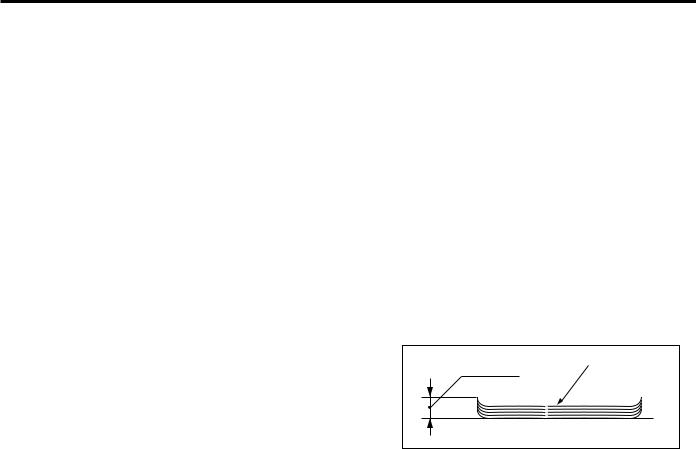
Note 2: The number of stacked sheets in staple mode must not exceed the stack sheet capacity for non-staple mode.
Note 3: Small size: |
8.5x5.5R |
Medium size: Everything other than small size, large size, special media.
Large size: |
8.5x14, 11x17 |
Special paper: Thin paper (16 lb. or less), thick paper (over 34 lb.), blueprint masters, OHP, etc.
Note 4: The stacking capacity of the option conforms to the stacking capacity of tray 1.
Paper curling: |
Maximum 10mm |
1 position staple: 11 x 17, 8.5 x 14, 8.5 x 11, 8.5 x 11R, 8.5 x 5.5R
2 position staple: 11 x 17, 8.5 x 14, 8.5 x 11, 8.5 x 5.5R
Maximum
Paper capacity: 2 trays: 100 +1000 = 1,100 sheets
3 trays:100 + 100 + 600 =
800 sheets
4 trays:100 x 4 = 400 sheets
Curl |
Five copy sheets |
|
Amount of sort
off-setting: 30mm
20mm (8.5 x 5.5R)
Copy |
|
|
|
|
|
|
|
|
|
Paper weight: |
|
13 lb. to 53 lb. papers |
|||||||
Stack capacity: |
|
(21 lb. high-quality paper) |
|||||||
With 2 standard trays |
|
|
|
|
|
||||
|
|
|
|
|
|
|
|
|
|
|
|
Small |
Medium |
Large |
Special |
||||
|
|
size |
size |
size |
media |
||||
|
|
|
|
|
|
|
|
|
|
|
Non- |
100 |
|
100 |
100 |
10 |
|
||
Tray 1 |
staple |
sheets |
sheets |
sheets |
sheets |
||||
Staple |
10 |
|
10 |
10 |
|
|
|
||
|
|
|
|
|
|||||
|
sets |
sets |
sets |
|
|
|
|||
|
|
|
|
|
|||||
|
Non- |
|
|
|
1000 |
300 |
50 |
|
|
Tray 2 |
staple |
|
|
|
sheets |
sheets |
sheets |
||
Staple |
|
|
|
50 |
20 |
|
|
|
|
|
|
|
|
|
|
|
|||
|
|
|
|
sets |
sets |
|
|
|
|
|
|
|
|
|
|
|
|||
|
|
|
|
|
|
|
|
||
|
|
|
|
|
|
|
|
|
|
Note 1: The above figures apply only to if stacked paper is all of the same size.
1
FS-107
Stapler kit
Staple ability |
Maximum 50 sheets (with 21 |
|||||||||||||||||||||||||||||
|
|
|
|
|
|
|
|
|
|
|
|
|
lb. paper, paper thickness |
|||||||||||||||||
|
|
|
|
|
|
|
|
|
|
|
|
|
less than 5mm) |
|||||||||||||||||
Stapler capacity: |
5,000 staples/cartridge |
|||||||||||||||||||||||||||||
Staple position: |
A = 8.6mm ± 3mm |
|||||||||||||||||||||||||||||
|
|
|
|
|
|
|
|
|
|
|
|
|
B = 8.6mm ± 3mm |
|||||||||||||||||
|
|
|
|
|
|
|
|
|
|
|
|
|
C = refer to following table |
|||||||||||||||||
|
|
|
|
|
|
|
|
|
|
|
|
|
D = 10.5mm ± 3mm |
|||||||||||||||||
|
|
|
|
|
|
|
|
|
|
|
|
|
E = 8.0mm ± 3mm |
|||||||||||||||||
|
|
|
|
|
|
|
|
|
|
|
|
|
|
|
|
|
|
|
|
|
|
|
|
|
|
|
|
|
|
|
|
Paper Size |
|
|
|
C (mm) |
|
||||||||||||||||||||||||
|
|
|
|
|
|
|
|
|
|
|
|
|
|
|
|
|
|
|
|
|
|
|
|
|
|
|
|
|
|
|
|
A3/A4 |
|
|
60±4 |
|
|
|
|
|
|
|
|
|
|||||||||||||||||
|
|
|
|
|
|
|
|
|
|
|
|
|
|
|
|
|
|
|
|
|
|
|
|
|
|
|
|
|
|
|
|
B4/B5 |
|
|
53±4 |
|
|
|
|
|
|
|
|
|
|||||||||||||||||
|
|
|
|
|
|
|
|
|
|
|
|
|
|
|
|
|
|
|
|
|
|
|
|
|
|
|
|
|
|
|
|
A4R/A5 |
|
|
90±4 |
|
|
|
|
|
|
|
|
|
|||||||||||||||||
|
B5R |
|
|
80±4 |
|
|
|
|
|
|
|
|
|
|||||||||||||||||
|
A5R |
|
|
63±4 |
|
|
|
|
|
|
|
|
|
|||||||||||||||||
|
F4 (8 x 13) |
|
|
90±4 |
|
|
|
|
|
|
|
|
|
|||||||||||||||||
|
F4 (8.125 x 13) |
|
|
91.5±4 |
|
|
|
|
|
|
|
|
||||||||||||||||||
|
F4 (8.25 x 13) |
|
|
93±4 |
|
|
|
|
|
|
|
|
|
|||||||||||||||||
|
|
|
|
|
|
|
|
|
|
|
|
|
|
|
|
|
|
|
|
|
|
|
|
|
|
|
|
|
|
|
|
F4 (8.5 x 13) |
|
|
95±4 |
|
|
|
|
|
|
|
|
|
|||||||||||||||||
|
11 x 17/8.5 x 11 |
|
|
52±4 |
|
|
|
|
|
|
|
|
|
|||||||||||||||||
|
8.5 x 14/8.5 x 11R |
|
|
95±4 |
|
|
|
|
|
|
|
|
|
|||||||||||||||||
|
5.5 x 8.5 |
|
|
95±4 |
|
|
|
|
|
|
|
|
|
|||||||||||||||||
|
5.5 x 8.5R |
|
|
60±4 |
|
|
|
|
|
|
|
|
|
|||||||||||||||||
|
|
|
|
|
|
|
|
|
|
|
|
|
|
|
|
|
|
|
|
|
|
|
|
|
|
|
|
|
|
|
|
|
|
|
|
|
|
|
|
|
|
|
|
|
|
|
|
|
|
|
|
|
|
|
|
|
|
|
|
|
|
|
|
|
|
|
|
|
|
|
|
|
|
|
|
|
|
|
|
|
|
|
|
|
|
|
|
|
|
|
|
|
|
|
|
|
|
|
|
|
|
|
|
|
|
|
|
|
|
|
|
|
|
|
|
|
|
|
|
|
|
|
|
|
|
|
|
|
|
|
|
|
|
|
|
|
|
|
|
|
|
|
|
|
|
|
|
|
|
|
|
|
|
|
|
|
|
|
|
|
|
|
|
|
|
|
|
|
|
|
|
|
|
|
|
|
|
|
|
|
|
|
|
|
|
|
|
|
|
|
|
|
|
|
|
|
|
|
|
|
|
|
|
|
|
|
|
|
|
|
|
|
|
|
|
|
|
|
|
|
|
|
|
|
|
|
|
|
|
|
|
|
|
|
|
|
|
|
|
|
|
|
|
|
|
|
|
|
|
|
|
|
|
|
|
|
|
|
|
|
|
|
|
|
|
|
|
|
|
|
|
|
|
|
|
|
|
|
|
|
|
|
|
|
|
|
|
|
|
|
|
|
|
|
|
|
|
|
|
|
|
|
|
|
|
|
|
|
|
|
|
|
|
|
|
|
|
|
|
|
|
|
|
|
|
|
|
|
|
|
|
|
|
|
|
|
|
|
|
|
|
|
|
|
|
|
|
|
|
|
|
|
|
|
|
|
|
|
|
|
|
|
|
|
|
|
|
|
|
|
|
|
|
|
|
|
|
|
|
|
|
|
|
|
|
|
|
|
|
|
|
|
|
|
|
|
|
|
|
|
|
|
|
|
|
|
|
|
|
|
|
|
|
|
|
|
|
|
|
|
|
|
|
|
|
|
|
|
|
|
|
|
|
|
|
|
|
|
|
|
|
|
|
|
|
|
|
|
|
|
|
|
|
|
|
|
|
|
|
|
|
|
|
|
|
|
|
|
|
|
|
|
|
|
|
|
|
|
|
|
|
|
|
|
|
|
|
|
|
|
|
|
|
|
|
|
|
|
|
|
|
|
|
|
|
|
|
|
|
|
|
|
|
|
|
|
|
|
|
|
|
|
|
|
|
|
|
|
|
|
|
|
|
|
|
|
|
|
|
|
|
|
|
|
|
|
|
|
|
|
|
|
|
|
|
|
|
|
|
|
|
|
|
|
|
|
|
|
|
|
|
|
|
|
|
|
|
|
|
|
|
|
|
|
|
|
|
|
|
|
|
|
|
|
|
|
|
|
|
|
|
|
|
|
|
|
|
|
|
|
|
|
|
|
|
|
|
|
|
|
|
|
|
|
|
|
|
|
|
|
|
|
|
|
|
|
|
|
|
|
|
|
|
|
|
|
|
|
|
|
|
|
|
|
|
|
|
|
|
|
|
|
|
|
|
|
|
|
|
|
|
|
|
|
|
|
|
|
|
|
|
|
|
|
|
|
|
|
|
|
|
|
|
|
|
|
|
|
|
|
|
|
|
|
|
|
|
|
|
|
|
|
Machine data
Power source: |
DC24V/5V (supplied from the |
|
main body) |
Maximum power |
|
Consumption: |
Maximum 70VA |
Weight: |
28.6 lb. |
External |
|
dimensions: |
Length 30.8 in. |
|
Depth 19.8 in. |
|
Height 15.4 in. |
Maintenance
Maintenance: |
Same as the main unit |
Machine environment
Temperature: |
50 to 86 F |
Humidity: |
10 to 80%RH |
|
(below condensation-forming |
|
conditions) |
Caution: The contents of this service manual may be changed without notice.
2
|
FS-107 |
CENTER CROSS SECTION |
|
Tray 1 |
Exit roller/A |
|
Conveyance roller |
|
Conveyance rollers |
Tray 2 |
Stapler unit |
|
|
|
Conveyance belt |
3
FS-107
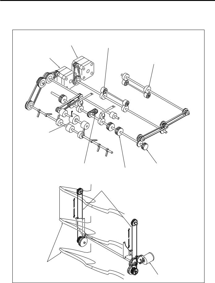
DRIVE SYSTEM DIAGRAM
Paper Conveyance Drive
Paper conveyance |
|
motor (M701) |
Conveyance roller |
|
|
Paper exit motor (M702) |
|
|
Conveyance roller |
Exit roller A |
|
Conveyance belt |
Paper jam release knob |
|
Conveyance roller |
|
Tray up/down wires |
Trays |
|
|
Tray up/down motor (M706) |
|
4 |
FS-107
Stapler Unit Drive
Stapler unit
Alignment plates
Stapler shift motor (M705)
Alignment motor
(rear) (M703)
Alignment motor (front) (M704)
5
FS-107
PAPER CONVEYANCE PATH
In the finisher, two different paper conveyance paths are used, changing by the mode selected.
Straight Mode
In this mode, paper conveyed to the finisher is exited straight into the tray. (For small size paper, the operation of OffsetMode/Stapling Mode takes place, even in the straight paper exit mode.)
6

FS-107
Offset Mode/Staple Mode
In the offset mode or staple mode, paper conveyed to the finisher is stacked once by the reverse rotation of the exit roller. In the offset mode, this stacked paper is offset by the paper alignment plates. In the staple mode, the paper is stapled. When the respective process is finished, the paper is exited to the tray by the exit roller.
Paper exit roller
Alignment plate
7

FS-107
This page left blank intentionally.
8
FS-107
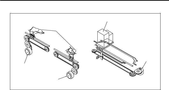
EXTERNAL SECTION
Composition |
|
|
Paper conveyance cover |
Optional tray 1 |
|
Tray 1 |
||
|
(FT-107) |
|
Conveyance plate |
Optional tray 2 |
|
(FT-107) |
||
|
||
Front door |
|
|
Tray 2 |
||
Stapler unit |
|
|
9
FS-107
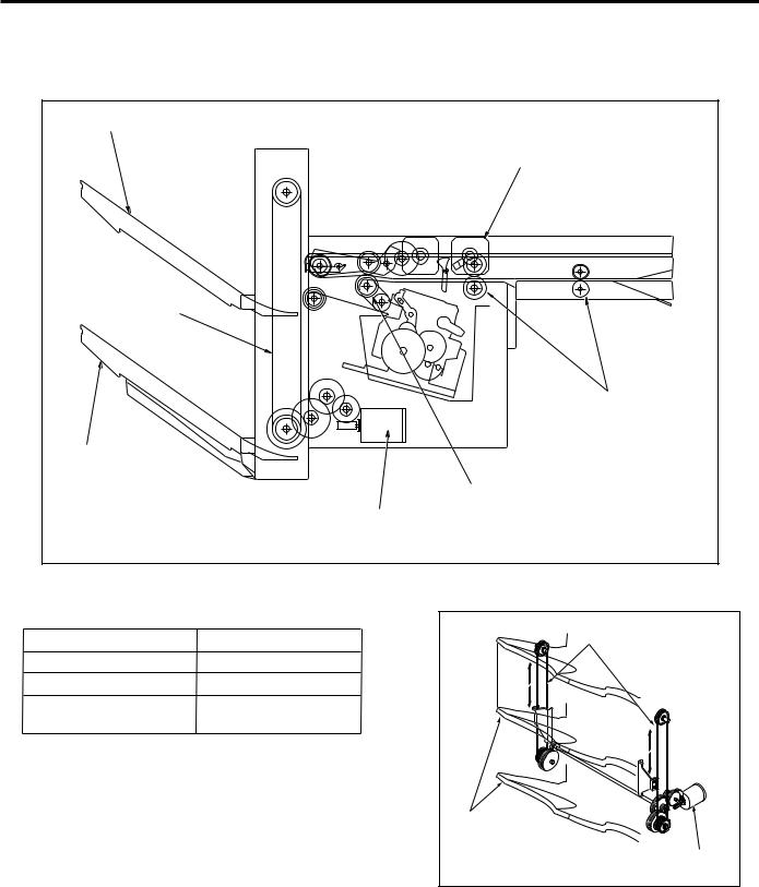
CONVEYANCE SECTION
Composition |
Tray 1 |
Paper conveyance motor (M701) |
Tray up/down wire |
Conveyance rollers |
Tray 2 |
Conveyance roller |
Tray up/down motor (M706) |
Mechanisms
Mechanism |
System |
Tray up/down wires |
|
||
Paper Conveyance |
Conveyance rollers |
|
Tray Up/Down *1 |
Wire drive |
|
Tray Up/Down Accident |
Shutter |
|
Prevention *2 |
|
|
*1 Tray up/down
The paper exit gate position is fixed; switching between trays is accomplished by changing the tray position up/down mechanism.
Trays
Tray up and down is done by the tray up/down
motor (M706), which the tray up/down wires to
Tray up/down
drive the tray up or down.
motor (M706)
10
FS-107
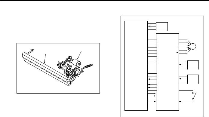
*2 Prevention of tray up/down accident
To prevent the accident insertion of the hand into the paper exit gate during tray motion up or down, the paper exit gate is equipped with a shutter. The shutter is driven by the reverse motion of the paper pressure motor (M707), closing the paper exit gate when the tray is in motion.
Paper pressure motor (M707)
Shutter
Conveyance Control |
|
|
|
5VDC |
|
|
|
PS3 |
PS3 |
|
|
SGND |
|
|
|
24VDC |
24VDC |
|
|
24VDC |
24VDC |
|
|
24VDC |
M701 OUT A |
M701 |
|
5VDC |
M701 OUT A |
||
|
|||
5VDC |
M701 OUT B |
|
|
SGND |
M701 OUT B |
|
|
SGND |
|
|
|
PGND |
|
|
|
PGND |
5VDC |
|
|
PGND |
PS702 |
PS702 |
|
|
SGND |
|
|
SGND |
|
|
|
SGND |
5VDC |
|
|
M ACK |
PS717 |
PS717 |
|
SGND |
SGND |
|
|
S REQ |
|
|
|
M RXD |
|
|
|
SGND |
24VDC |
|
|
S ACK |
|
MS701 |
|
M REQ |
|
||
SGND |
|
|
|
M TXD |
MS701 |
|
|
MAIN BODY |
FS CB |
|
Conveyance is accomplished by the drive force of the M701 (paper conveyance motor), which is transmitted to the conveyance rollers. The M701 is linked with the main body, so that rotation is set to low or high speed according to the conveyance movement during copying.
The M701 is controlled by the FS CB (FS control board). Related signals are provided by the PS702 (paper entrance detect PS), PS717 (conveyance cover open/ close detect PS) and the MS701 (front door switch) and PS3 (paper exit PS) of the main body.
1.Operation
As paper passes by the PS3 of the main body, the M701 conveys the paper at a low speed in relation with the paper exit velocity of the main body. When the end of the paper passes through the PS3, the M701 then conveys the paper at high speed. The M701 again changes to low speed after the specified period of time when the end of the paper passes through the PS702, ready to convey the next sheet of paper.
11
FS-107
2.Signals
a. Input signals
(1)PS3 (PS3 -> PRDB)
When the main body paper exit section detection signal detects paper, [H] is output.
(2)PS702 (PS702 -> FS CB)
Conveyance section paper entrance detection signal [L]: No paper is present
[H]: Paper is present
(3)PS717 (PS717 -> FS CB)
Conveyance plate opening/closing detection signal [L]: Conveyance plate open
[H]: Conveyance plate closed
(4)MS701 (MS701 -> FS CB)
Power supply line for each load
When the finisher front door is closed, 24VDC is supplied to each load.
(5)S ACK (MAIN BODY -> FS CB)
Transmission of OK signal from the main body to the finisher.
(6)M TXD (MAIN BODY -> FS CB)
Serial data sign sending the movement condition of the main body to the finisher.
(7)M REQ (MAIN BODY -> FS CB)
Transmission of request signal from the main body to the finisher.
b.Output signals
(1)M701 OUTA, M701 OUTA, M701 OUTB, M701 OUT B (FS CB -> M701)
M701 drive control signal
24V
0V
(2)M ACK (FS CB -> MAIN BODY)
Transmission of OK signal from the finisher to the main body.
(3)S REQ (FS CB -> MAIN BODY)
Transmission of request signal from the finisher to the main body.
(4)M RXD (FS CB -> MAIN BODY)
Serial data sign sending the movement condition of the finisher to the main body CB.
12
FS-107
Tray Up/Down Control
24VDC |
|
|
|
|
|
|
|
|
|
|
M706 DRIVE 1 |
|
|
|
M706 |
|
|||
|
|
|
|
|
|||||
24VDC |
|
|
|
M706 DRIVE 2 |
|
|
|
|
|
|
|
|
|
|
|
||||
24VDC |
|
|
|
|
|
|
|
||
|
|
|
|
|
|
|
|||
5VDC |
|
|
|
|
|
|
|
||
|
|
|
|
|
|
|
|||
5VDC |
|
5VDC |
|
|
|
|
|
||
|
|
|
|
|
|
||||
SGND |
|
|
|
|
PS706 |
|
|||
SGND |
|
PS706 |
|
|
|
|
|||
|
|
|
|
|
|||||
PGND |
|
SGND |
|
|
|
|
|
||
|
|
|
|
|
|
||||
PGND |
|
|
|
|
|
|
|
||
|
|
|
|
|
|
|
|||
PGND |
|
5VDC |
|
|
|
|
|
||
|
|
|
|
|
|
||||
|
|
|
|
PS703 |
|
|
|
PS703 |
|
|
|
|
|
|
|
||||
SGND |
|
SGND |
|
|
|
|
|
||
|
|
|
|
|
|
||||
SGND |
|
|
|
|
|
|
|
||
|
|
|
|
|
|
|
|||
M ACK |
|
|
5VDC |
|
|
|
|
|
|
|
|
|
|
|
|
|
|||
SGND |
|
|
|
|
PS716 |
|
|||
S REQ |
|
|
PS716 |
|
|
|
|
||
|
|
|
|
|
|||||
M RXD |
|
|
SGND |
|
|
|
|
|
|
|
|
|
|
|
|
|
|||
SGND |
|
24VDC |
|
|
|
|
|
||
|
|
|
|
|
|
||||
S ACK |
|
|
|
|
|
|
|
||
|
|
|
|
|
|
||||
M REQ |
|
|
|
|
MS702 |
|
|||
|
|
|
|
||||||
SGND |
|
|
|
|
|
|
|||
|
|
|
|
|
|
|
|||
M TXD |
|
|
MS702 |
|
|
|
|
|
|
|
|
|
|
|
|
||||
|
|
|
|
|
|
|
|
|
|
MAIN BODY |
FS CB |
|
|
|
|
|
|||
|
|
|
|
|
|
|
|
|
|
|
|
|
|
|
|
|
|
|
|
The paper exit position of the FS is fixed, the selected tray is elevated or lowered to the paper exit position. Control of the tray up/down is by the M706 (tray up/down motor) which drives wires which is connected to and moves the trays up and down.
The M706 is controlled by the FS CB (FS control board). Related signals are provided by the PS703 (paper exit detect PS), PS706 (tray lower limit detect PS), PS716 (tray count PS) and the MS702 (shutter switch).
1.Operations
a. Tray lower limit detection operation
With the sub power swich turnd ON, and the PS706 OFF, the M706 is reversed and the tray is lowered until the PS706 is turned ON.
b.Tray count operation
One, two, or no optional trays can be installed.
If PS716 goes OFF after the low limit of the tray has been detected, the machine judges that no optional trays are installed.
When PS716 is ON, optional tray 1 is in place; in this condition the M706 rotates normally, raising the tray one step up until PS716’s detection position where motion is stopped. Whether PS716 is ON or OFF at this point determines whether optional tray 2 is in place or not.
The number of trays is counted by means of a series of operations.
After the tray count, the default tray that was set in the key operator mode is set in the exit position.
c.Tray movement operation
If the exit tray has been selected at the LCD, then when copying starts M706 turns ON and moves the selected tray so that it sets into the exit position.
The number of times PS703 switches ON and OFF sets the selected tray into the paper exit position.
d.Shutter switch operation
While the tray is in motion, the shutter, which prevents the fingers or foreign objects from entering the paper exit gate, is closed, with MS702 in the ON position supplying 24VDC to the various loads. While the tray is being raised or lowered the shutter is opened and MS702 is OFF, interrupting the flow of electricity and halting the motion of the FS.
13

FS-107
2.Signals
a. Input signals
(1)PS706 (PS706 -> FS CB)
Tray lower limit detection signal [L]: Not at lower limit [H]:Lower limit
(2)PS703 (PS703 -> FS CB)
Paper exit detection signal [L]: Top face
[H]:Not at top face
(3)PS716 (PS716 -> FS CB)
Tray installation detection signal [L]: No tray
[H]:Tray in position
(4)PS702 (PS702 -> FS CB)
The power supply line for each load.
24VDC is supplied to each load when the shutter is closed.
b.Output signal
(1)M706 DRIVE 1, 2 (FS CD -> M706)
M706 drive control signal
The drive direction of the M706 is controlled by two signals which change the direction of the electrical current.
14
Loading...