


SERVICE MANUAL
MODEL
FS-105
JUNE 1998
CSM-FS105

CONTENTS
TABLE OF CONTENTS |
|
SAFETY PRECAUTIONS........................................................ |
v |
FS-105 |
|
SPECIFICATIONS ................................................................. |
1 |
Type ............................................................................... |
1 |
Functions ....................................................................... |
1 |
Stapler Kit ...................................................................... |
1 |
Machine Data ................................................................. |
1 |
Maintenance .................................................................. |
1 |
Operating Environment ................................................. |
1 |
CENTER CROSS SECTION ................................................. |
3 |
DRIVE SYSTEM DIAGRAM .................................................... |
4 |
Paper Conveyance System Drive .................................. |
4 |
Stapler Unit Drive ........................................................... |
4 |
EXTERNAL SECTION ........................................................... |
5 |
Construction .................................................................. |
5 |
Disassembly and Reassembly .................................... |
5 |
CONVEYANCE SECTION ..................................................... |
8 |
Construction .................................................................. |
8 |
Mechanisms .................................................................. |
8 |
Disassembly and Reassembly .................................. |
11 |
Paper Feed Motor (M801) Control ............................... |
13 |
Conveyance Drum (M807) Control .............................. |
14 |
Tray Up/Down (M804) Control ..................................... |
15 |
PAPER EXIT/STAPLER UNIT SECTION ............................. |
16 |
Construction ................................................................ |
16 |
Mechanisms ................................................................ |
16 |
Disassembly and Reassembly .................................. |
18 |
Paper Alignment Control ............................................. |
20 |
Paper Exit (M805) Control ............................................ |
21 |
Paper Stacking Control ............................................... |
22 |
Stapler Movement (M806) Control ............................... |
24 |
Stapler Control ............................................................. |
25 |
OTHER CONTROL FUNCTIONS ....................................... |
27 |
Power On Operation .................................................... |
27 |
DIAGRAMS |
|
ELECTRICAL PARTS LAYOUT DIAGRAM .......................... |
28 |
CONNECTOR LAYOUT DIAGRAM ...................................... |
29 |
iii

This page left blank intentionally.
iv
FS-105
PRODUCT SPECIFICATIONS
Type
Type: Drum inverting type, multi-tray finisher
Functions
Kinds of copy paper: Same as main body
Copy paper size: A11x17R, 8.5x14R, 8.5x11, 8.5x11R, 8.5x5.5, 8.5x5.5R, 5.5x8.5R
Modes |
|
|
: Available |
: Not available |
|||||||
Mode |
Tray |
|
Tray 1 |
|
Tray 2 |
|
Tray 3 |
||||
|
|
|
|
||||||||
|
|
|
|
|
|
|
|
|
|
|
|
Through mode |
|
|
|
|
|
|
|
|
|
|
|
Offset mode |
|
|
|
|
|
|
|
|
|
|
|
Staple mode |
|
|
|
|
|
|
|
|
|
|
|
Sheet capacity |
|
|
|
|
|
|
|
|
|
|
|
Tray |
Mode |
|
Small sizes |
|
Middle sizes |
|
Large sizes |
|
Special paper |
||
|
|
|
|
||||||||
Tray 1 |
Through mode |
|
100 |
|
100 |
|
|
100 |
|
|
10 |
Tray 2, |
Through mode |
|
300 |
|
500 |
|
|
300 |
|
|
– |
Tray 3 |
Offset mode |
|
– |
|
500 |
|
|
300 |
|
|
– |
|
Staple mode |
|
|
|
|
|
|
|
|
– |
|
|
|
25 sets (Note) |
|
|
|
||||||
|
|
|
|
|
|
|
|
|
|
|
|
The above numbers apply for same-size paper (22 lb. ,standard paper) stacked continuously.
Small sizes |
: 5.5x8.5R |
Middle sizes |
: 8.5x11, 8.5x11R, 8.5x5.5, 8.5x5.5R |
Large sizes |
: 11x17R, 8.5x14R |
Special paper : Other than standard paper (thin paper, thick paper, blueprint masters, OHP film etc.)
Note: The maximum capacity (500 or 300 sheets) should not
be exceeded. |
|
Paper weight |
|
Tray 1: |
14 - 54 lb. |
Tray 2/3: |
16 - 44 lb. |
Copy paper curling: |
10 mm maximum |
Curling |
Copy paper (5 sheets) |
Offset amount: 30 mm (offset/group mode)
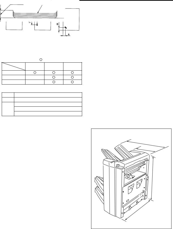
Stapler Kit
Number of copies that can be stapled together:
50 maximum (22 lb. fine quality paper, thickness 5 mm maximum)
Staple position:
A = 9 mm (non-adjustable)
B = 10 mm (±3 mm adjustable) C = 90 mm (±4 mm adjustable)
Stapler capacity:
5000 staples/cartridge
Machine Data
Power source: 24 V DC / 5 V (supplied from main body)
Max. power consumption:
100 VA (FS-105 only)
Weight: approximately 72 lb. (with base)
Machine dimensions
Unit: inches |
21.5 |
10.4 |
24.5 |
.6 |
23 |
1

FS-105
Maintenance
Maintenance: Same as main body
Operating Environment
Temperature: |
50°F ~ 91°F |
Humidity: |
20% to 80% RH |
Note: The contents of this manual may be changed without prior notice.
2
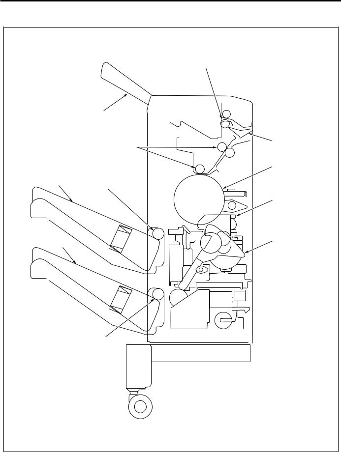
FS-105
CENTER CROSS-SECTIONAL DRAWING
Paper exit roller
Tray 1 |
|
Conveyance rollers |
Switching |
guide |
|
|
Conveyance drum |
Tray 2
Paper exit roller (A)
Stapler unit
Tray 3 |
Exit lever |
|
Paper exit roller (A)
3

FS-105
DRIVE SYSTEM DRAWING
Paper Conveyance System Drive
Conveyance rollers
Lift wire (rear)
Paper exit roller
Conveyance drum
drive motor (M807)
Paper exit roller (A)
Tray 2 motor (M810)
Timing belt
Tray 3 motor |
Paper exit roller (A) |
|
(M811) |
||
|
Paper feed motor (M801)
Conveyance drum
Tray up/down motor (M804)
Lift wire (front)
Stapler Unit Drive
Alignment motor |
Alignment plate |
Stapler unit (rear) |
|
||
(rear)(M808) |
(rear) |
|
|
|
|
|
Alignment plate |
Stapler unit (front) |
|
|
|
|
(front) |
|
|
Exit lever |
|
|
Alignment motor |
Stapler movement |
|
motor (M806) |
|
|
(front)(M809) |
|
|
|
|
|
|
Paper exit motor |
|
|
(M805) |
|
|
4 |
FS-105
EXTERNAL SECTION
Construction
Release lever
Top cover
Tray 1 
 Upper rear cover
Tray 2 
 Rear cover
Tray 3
Front cover 
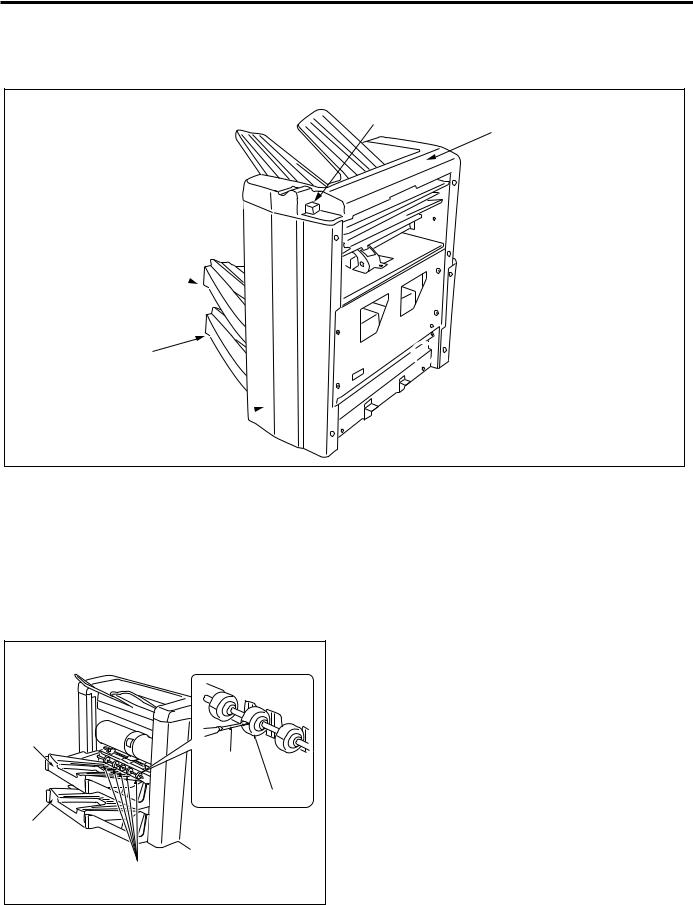
Disassembly and Reassembly
Replacing the paper exit roller (A) (for tray 2)
 Caution: Be sure that the power cord has been unplugged from the power outlet.
Procedure
(1)Insert a flatbladed screwdriver or similar tool into the joint of a paper exit roller (A), pry the roller open, and remove it. Remove all paper exit rollers (A) (5 rollers) in this way.
Tray 2 |
Flatblade |
screwdriver |
Paper exit rollers (A) |
Tray 3 |
Paper exit roller (A) |
(2)To install new rollers, snap two roller parts (top and bottom) onto the exit roller shaft (5 locations).
5

FS-105
Replacing the paper exit roller (A) (for tray 3)
Procedure
(1)Use the operation panel on the main body to specify tray 3 and raise tray 2 to the topmost position.
(2)Turn the power OFF of the main body and unplug the power cord from the power outlet.
 Caution: Be sure that the power cord has been unplugged from the power outlet.
(3)Insert a flatbladed screwdriver or similar tool into the joint of apaper exit roller (A), pry the roller open, and remove it. Remove all paper exit roller (A) (5 rollers) in this way.
Tray 2 |
|
|
Flatblade |
Tray 3 |
screwdriver |
Paper exit roller (A) |
Paper exit rollers (A) |
|
(4)To install new rollers, snap two roller parts (top and bottom) onto the exit roller shaft (5 locations).
Removing and Reinstalling tray 2
 Caution: Be sure that the power cord has been unplugged from the power outlet.
Procedure
(1)Remove the two set screws, then remove the connector cover.
Tray 2 |
Set screws |
Tray 3 |
Connector cover |
(2) Disconnect the two connectors (CN728, CN751).
Connector |
(CN728) |
Tray 2 |
Connector |
(CN751) |
(3)Remove the two set screws, then remove the stopper bracket (front).
(4)Lift the front side of tray 2 up, then rotate it towards the rear and remove it.
6
FS-105
|
Stopper bracket |
|
(front) |
|
Set |
|
screws |
Tray 3 |
Tray 2 |
|
(5) Reinstall tray 2 in the opposite sequence to removal.
Removing and Reinstalling tray 3
 Caution: Be sure that the power cord has been unplugged from the power outlet.
Procedure
(1)Remove tray 2.
(2)Remove the two set screws, then remove the connector cover. (Refer to “Removing and Reinstalling tray 2”.)
(3)Disconnect the two connectors (CN729, CN752). (Refer to “Removing and Reinstalling tray 2”.)
(4)Remove the two set screws, then remove the stopper bracket (front). (Refer to “ Removing and Reinstalling tray 2”.)
(5)Lift the front side of tray 3 up, then rotate it towards the rear and remove it. (Refer to “ Removing and Reinstalling tray 2”.)
(6)Reinstall tray 3 in the opposite sequence to removal.
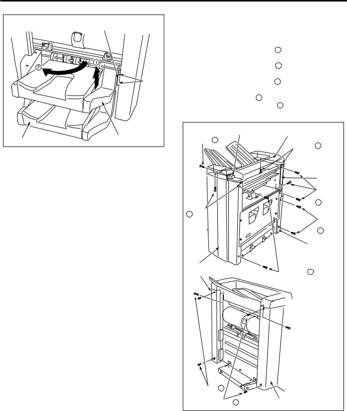
Removing and Reinstalling the external covers
 Caution: Be sure that the power cord has been unplugged from the power outlet.
Procedure
(1)Remove the four set screws A , then remove the front cover.
(2)Remove the five set screws B , then remove the rear cover.
(3)Remove the three set screws C , then remove the upper rear cover.
(4)Remove the set screw D, then remove the release lever.
(5)Remove the four set screws E , then release the top cover.
Release lever |
Top cover |
|
|
|
|
|
|
Set screw D |
Set screws |
E |
|
|
|||
|
|
|
Upper rear |
|
|
|
cover |
|
|
|
Set |
Set |
|
|
screws |
|
|
C |
|
screws |
|
|
|
E |
|
|
Set |
|
|
|
|
|
|
|
screws |
|
|
|
B |
|
|
Rear |
|
|
|
cover |
|
Front cover |
|
|
|
Rear |
Set screws |
A |
|
|
|
|
|
cover |
|
|
|
Set screws B |
|
|
|
Set screws A |
Front cover |
|
|
(6)Reinstall the external covers in the opposite sequence to removal.
7
 Loading...