


DiMAGE Scan Multi PRO

HARDWARE MANUAL
9222-2887-11 P-A208
E
BEFORE YOU BEGIN
2
This manual may not be copied in part or whole without prior
written permission from Minolta. Every necessary precaution
has been taken to ensure the accuracy of this instruction manual. Minolta is not responsible for any loss or damage caused
from the operation of this product.
Thank you for purchasing this Minolta product.Please take the time to read through this instruction manual so you can enjoy all the features of your new scanner.
This manual contains information regarding products introduced before September, 2002. To
obtain compatibility information for products released after this date, contact a Minolta Service
Facility (www.minoltasupport.com). This product is designed to work with accessories manufactured and distributed by Minolta. Using accessories or equipment not endorsed by Minolta may
result in unsatisfactory performance or damage to the product and its accessories.
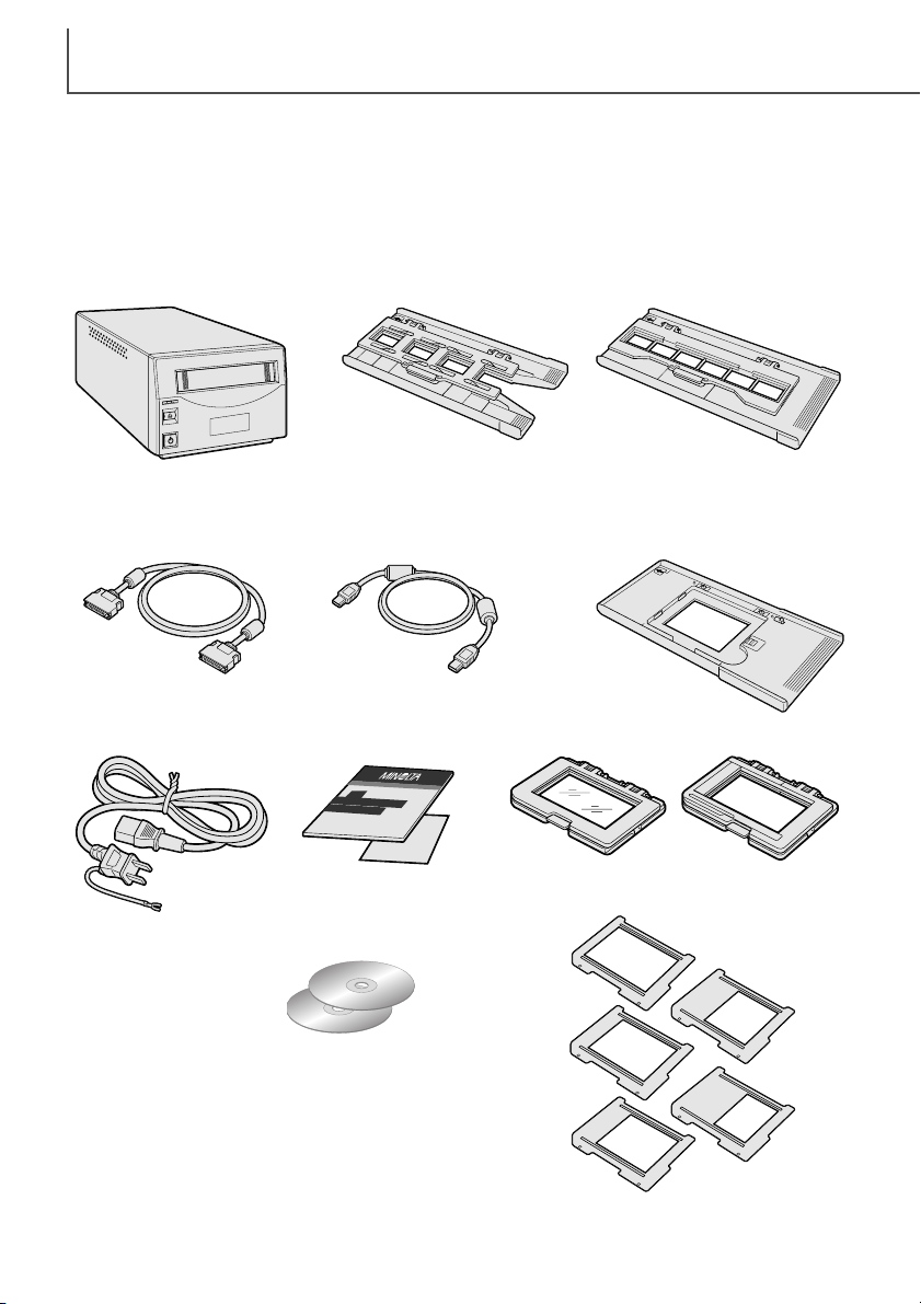
Check the packing list before using this product.If any items are missing, immediately contact
your dealer.
AC power cord
(Shape of plug varies
with destination)
Scanner unit
Slide Mount Holder
SH-P1
35mm Film Holder
FH-P1
Universal Holder
UH-P1
Standard Attachment HA-P1
Glassless Attachment HA-P2
Film Mask Set FM-P1
SCSI cable SC-P1 IEEE 1394 cable FC-P1
DiMAGE Scan Utility CD-ROM,
DiMAGE Instruction Manuals-CD-ROM
Quick Reference Guide
and Minolta International
Warranty Certificate

3
FOR PROPER AND SAFE USE
Read and understand all warnings and cautions before using this product.
WARNING
• Use only within the voltage range specified on the unit. Inappropriate current may cause
damage or injury through fire or electric shock.
• Do not disassemble this product. Electric shock may cause injury if a high-voltage circuit inside
the product is touched. Take the product to a Minolta Service Facility when repairs are required.
• Immediately unplug the unit and discontinue use if the product is dropped or subjected to an
impact in which the interior is exposed. The continued use of a damaged product may cause
injuries or fire.
• Store this product out of reach of children. Be careful when around children not to harm them
with the product or parts.
• Do not operate this product or handle the power cord with wet hands. Do not place a container
with liquid near the product. If liquid comes in contact with the product, immediately unplug the
unit. The continued use of a product exposed to a liquid may cause damage or injury through
fire or electric shock.
• Do not insert hands, inflammable objects, or metal objects such as paper clips or staples into
this product. It may cause damage or injury through fire or electric shock. Discontinue use if an
object enters the product.
• Do not use the product near inflammable gases or liquids such as gasoline, benzine, or paint
thinner. Do not use inflammable products such as alcohol, benzine, or paint thinner to clean the
product. The use of inflammable cleaners and solvents may cause an explosion or fire.
• When unplugging the unit, do not pull on the power cord. Hold the plug when removing the cord
from an outlet.
• Do not damage, twist, modify, heat, or place heavy objects on the power cord. A damaged cord
may cause damage or injury through fire or electric shock.
• If the product emits a strange odor, heat, or smoke, discontinue use. Immediately unplug the
product. The continued use of a damaged product or part may cause injuries or fire.
•Take the product to a Minolta Service Facility when repairs are required.
• This product should only be operated in the upright position. Inappropriate placement may result
in fire.
• Damage or injury through fire or electric shock may result if the product is used or stored in the
following conditions:
In humid or dusty environments
In direct sunlight or hot environments
In smoky or oily areas
In unventilated areas
On unstable or unlevel surfaces
• Insert the plug securely into the electrical outlet.
• Do not use if the cord is damaged.
• Do not connect the ground to a gas pipe, telephone ground, or water pipe. Improper grounding
can result in injury from electric shock.
• Unplug the product when cleaning or when the unit is not in use for long periods.
•Periodically check that the power cord is not damaged and the plug is clean. Dust and dirt that
may collect between the prongs of the plugs may result in fire.
CAUTION

TABLE OF CONTENTS
4
System requirements......................................................................................................5
Names of parts ..............................................................................................................6
Scanner setup ................................................................................................................7
Removing the optics locking screw ....................................................................7
Tr ansporting the scanner ........................................................................7
Before connecting the scanner to the computer ................................................7
Connecting the SCSI cable ................................................................................8
Connecting the IEEE 1394 (FireWire) cable ......................................................9
Auto Power Save ................................................................................................9
Loading the film holders ..............................................................................................10
Handling film......................................................................................................10
Where is the emulsion? ....................................................................................10
Loading 35mm film strips ..................................................................................10
Loading 35mm mounted slides ........................................................................10
Inserting attachments into the Universal holder................................................11
Using the standard attachment ........................................................................12
Using the glassless attachment ........................................................................12
Multi-format Set HS-P1 (sold separately)..........................................................13
Loading a film holder into the scanner..............................................................15
Ejecting a film holder ........................................................................................15
Scanner notes ..............................................................................................................16
Easy Scan Utility ..............................................................................................16
About the DiMAGE Scan Utility ........................................................................16
Film format and type settings............................................................................16
Disconnecting the scanner................................................................................16
SCSI cable ............................................................................................16
IEEE 1394 (FireWire) cable ..................................................................16
Digital ICE
3
system requirements......................................................................18
Scanner resolution ............................................................................................19
Scanner color profiles ......................................................................................19
Job file lists ..............................................................................................................20
35mm ..............................................................................................................20
6 X 4.5 ..............................................................................................................21
6 X 6 ..............................................................................................................22
6 X 7 ..............................................................................................................23
6 X 8 ..............................................................................................................24
6 X 9 and Multi-format 6 X 9 ............................................................................25
Multi-format 35mm ............................................................................................25
Troubleshooting ............................................................................................................26
Checking software installation - Windows ........................................................27
Technical support ..............................................................................................28
Warranty and product registration ....................................................................28
Image data sheet..........................................................................................................29
Technical specifications ................................................................................................30
This manual contains information specific to this model scanner. This includes hardware setup
and use as well as notes about software operation for this model scanner. See the supplied
DiMAGE Scan Utility software manual for information on the installation and operation of the scanner software.

5
SYSTEM REQUIREMENTS
SCSI: Pentium 166MHz or later processor.
IEEE 1394: Pentium II or later processor.
A Pentium III processor is recommended when
scanning with 16-bit color depth. For Digital ICE
3
requirements, see page18.
A minimum of 96 MB of RAM (Windows (128MB with Windows XP)) or 64 MB of RAM (Macintosh) in addition to the requirements for the operating system and applications is required. 256 MB or more is necessary
when scanning with 16-bit color depth; 512 MB or more is recommended.
For Digital ICE
3
requirements, see page18.
A High Color (16bit) 640 x 480 pixel monitor is
required.
1024 x 768 pixels is recommended.
TWAIN driver compatible with Photoshop 4.0.1,
5.0.2, 5.5, 6.0, and 7.0, and PhotoshopLE 5.0.
Recommended SCSI boards: Adaptec SCSI Card
19160, Adaptec SCSI Card 29160, Adaptec SCSI
Card 29160N.
Recommended IEEE boards: Adaptec Fireconnect
4300, PROCOMP SpeedDemon 400P. Standard
OHCI compatible non-DV-dedicated IEEE 1394
ports guarantied by the computer manufacturer can
be used.
PC / AT compatible computers
Operation is not guarantied for custom or home-built machines.
The scanner cannot be used with notebook computers.
SCSI: preinstalled Windows 98, 98 Second Edition,
Me, 2000 Professional, NT 4.0, XP.
IEEE 1394: preinstalled Windows Me, 2000
Professional, XP.
Mac OS 8.6* to 9.2.2, and
OS 10.1.3 to 10.1.5.
A 640 x 480 pixel monitor capable of displaying
32,000 colors is required.
1024 x 768 pixels is recommended.
SCSI: PowerPC 604 or later
FireWire: PowerPC G3 or later.
PowerPC G4 processor is recommended when
scanning with 16-bit color depth. For Digital ICE
3
requirements, see page18.
Plug-in compatible with Photoshop 5.0.2, 5.5, 6.0,
and 7.0, and PhotoshopLE 5.0.
2 GB or more of available hard disk space is required. 6 GB or more of available hard disk space is necessary when scanning with 16-bit color depth; 8 GB or more is recommended.
For Digital ICE
3
requirements, see page18.
Macintosh
Recommended SCSI boards: Adaptec
PowerDomain 29160N, PowerDomain 2930U,
PowerDomain 2940UW, or PowerDomain
2940U2W.**
Only the standard built-in IEEE interface supplied
by Apple Computer, Inc.
* To use preinstalled Mac OS 8.6 with a built-in FireWire port, a Firewire 2.2 to 2.3.3 extension
must be installed. This software can be downloaded free of charge from the apple web site at
http://www.apple.com.
**Boards must be guarantied by the manufacturer to work with the computer and operating sys-
tem.
The computer and the operating system must be guarantied by the manufacturer to support IEEE
1394 (FireWire), or SCSI interface.
Check the Minolta web site for the latest compatibility information:
Europe: http://www.minoltasupport.com
North America: http://www.minoltausa.com.
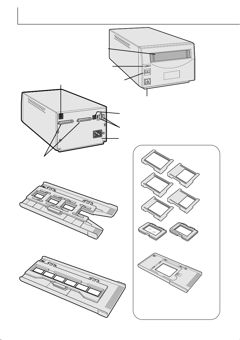
NAMES OF PARTS
6
Slide Mount Holder (p. 10)
35mm Film Holder (p. 10)
Universal Holder (p. 11)
Film attachments
Film masks
Front door
Indicator lamp
Power switch
Eject button
SCSI ID switch
IEEE 1394 (FireWire) ports
Dip switch
AC terminal
SCSI ports
7
SCANNER SETUP
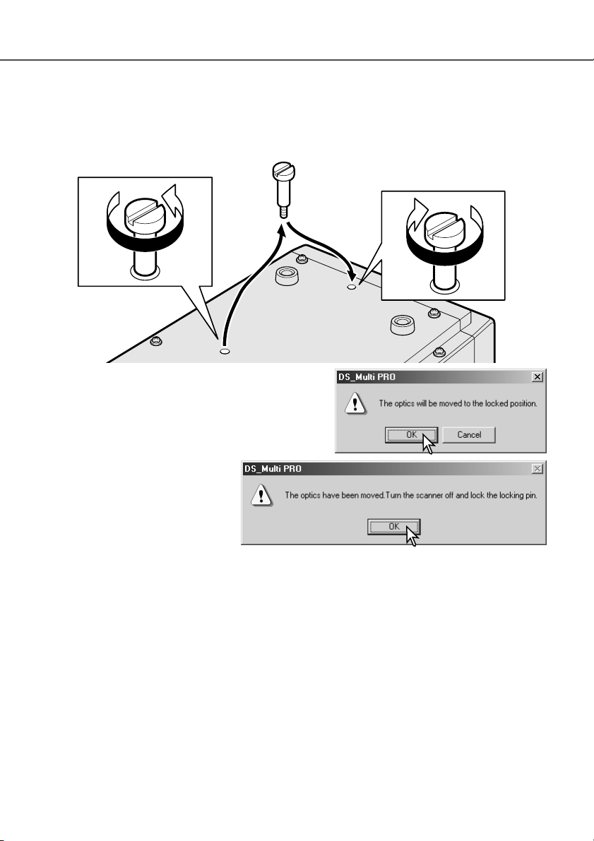
Transporting the scanner
To prevent damage when transporting the scanner, the
optics locking screw must be used.Before inserting the
screw in the lock position, the scanner must be initialized with the DiMAGE Scan Utility.
With the scanner connected to the
computer and the DiMAGE Scan
Utility running, press the control
(Windows) or command (Macintosh)
key plus the shift and L keys simultaneously. A window indicating the
command will be displayed;click the
OK button to move the optics to the lock position.
A message stating the completion of the operation will be displayed;click the OK button. Turn off
the computer and scanner.Disconnect the cable and power cord from the scanner and screw the
optic locking screw in the lock position.
Removing the optics locking screw
Before the scanner can be used, the optics locking screw on the bottom panel of the scanner
must be removed with a flat-head screwdriver. The locking screw is necessary to transport the
scanner.Place the screw in the storage position toward the front of the scanner body for future
use.
Before connecting the scanner to a computer
Before connecting the scanner to a computer, the the DiMAGE Scan Utility must first be installed.
Read the software instruction manual for the installation procedure.
The scanner should be placed on a level surface free from vibrations. It should be located away
from direct sunlight and in a clean, dry, well-ventilated area.
SCANNER SETUP
8
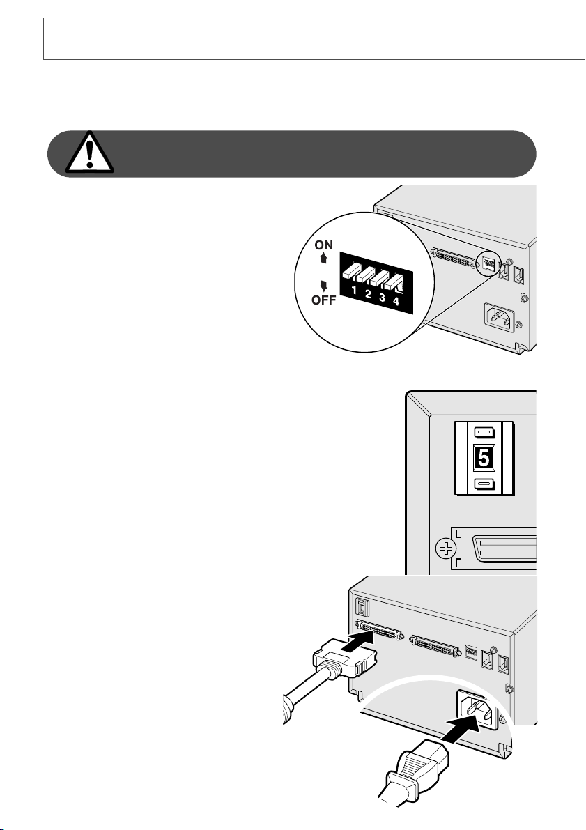
Connecting the SCSI cable
The scanner is supplied with an ultra SCSI D-sub half-pitch 50-pin cable. Contact your dealer if a
different cable is required.
The computer and all peripheral devices must be off
before connecting the scanner.
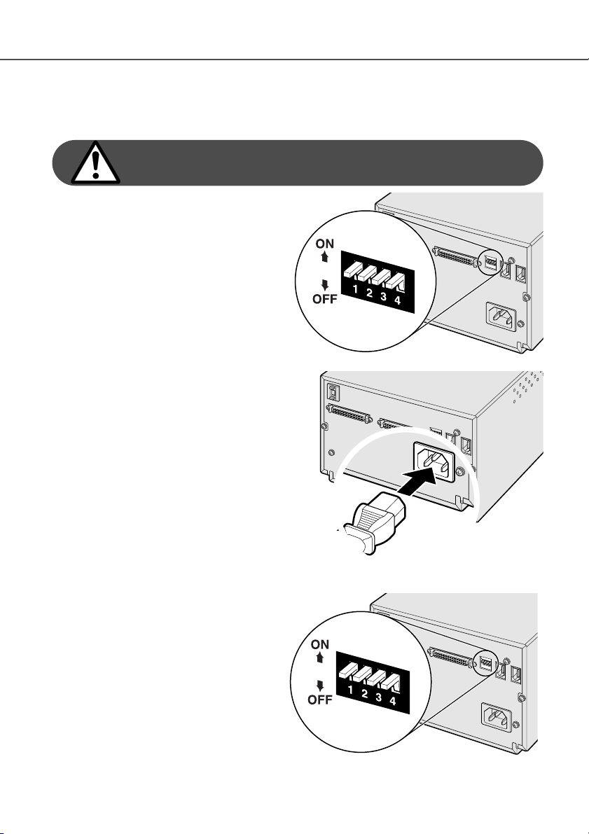
The terminator dip switch on the back of the
scanner eliminates the need for an external terminator. If the scanner is to be the only SCSI
device connected to the computer or it is the last
device in a daisy chain, switch number 1 should
be in the on position; terminating the SCSI chain
helps to suppress noise, not terminating a chain
can cause slowdowns, data errors, and crashes.
If the scanner is to be connected somewhere
within a daisy chain, switch 1 should be in the
off position. The initial setting for all the switches
is on. Dip switch 4 must be in the on position to
use a SCSI interface.
Connect the scanner to the computer or SCSI
chain with the cable. Either SCSI port can be
used for the connection.
Plug the power cord into the back of the unit.
The other end of the power cord should be
plugged into a grounded outlet.
Set the SCSI ID for the scanner by pressing the buttons above and
below the ID number window. Devices in the same chain must have
unique ID numbers. Depending on the computer system, some SCSI
IDs may already be assigned:
IBM PC/AT 7 - SCSI host adapter
Macintosh 0 - internal hard drive
3 - internal CD-ROM drive
7 - operating system
IDE Macintosh systems do not use SCSI ID 0 for the hard drive. SCSI
ID 3 is available on the external bus on Macintosh systems with a
dual bus.
9
Connecting the IEEE1394 (FireWire) cable
The scanner is supplied with an IEEE 1394 (FireWire) cable. Up to 63 devices can be attached to
a computer using this interface. However, the number of devices is limited to 16 when using a
daisy-chain configuration.
The computer and all peripheral devices must be off
before connecting the scanner.
Set dip switch number 4 to the off position to
active the IEEE ports. Switch 4 must be
moved to the on position if a SCSI cable is
used.
Connect the scanner to the computer or
IEEE peripheral chain with the cable. Either
IEEE port can be used for the connection.
Plug the power cord into the back of the unit.
The other end of the power cord should be
plugged into a grounded outlet.
Auto Power Save
The scanner automatically turns the scanning light source off during long periods of
inactivity to save energy and preserve the life
of the fluorescent tube. Though not recommended, the auto-power-save function can
be disabled by setting dip switch number 2 to
the off position.
LOADING THE FILM HOLDERS
10
Loading 35mm mounted slides
The Slide Mount Holder SH-P1 is for mounted 35mm film.
Up to four slide can be placed in the holder. Slide mounts
must be between 1mm and 2mm thick to fit the holder.
Glass mounts cannot be used; the glass refracts the light
resulting in distorted and unevenly illuminated scans.
With the cover hinges away from you, open the holder by
lifting on the latch on the cover.
Handling film
To achieve the best possible reproduction from the scanner, the film and film holder should be
free from dust and dirt. Always work with processed film in a clean, dust-free environment. Handle
film by the edges or mount to prevent fingerprints and dirt marring the image area. Special lint
free gloves are available from photographic equipment retailers for film handling as well as antistatic cloths, brushes, and blowers for removing dust. Film cleaner can be used to remove oil,
grease, or dirt from film; carefully follow the manufacturer's instructions and precautions for the
film cleaning solvent.
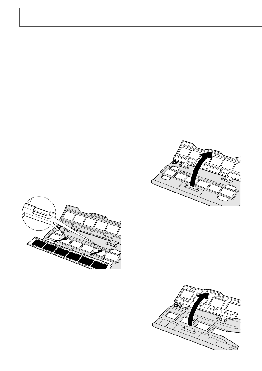
Loading 35mm film strips
The 35mm Film Holder FH-P1 is for unmounted 35mm
film. Film strips up to six frames in length can be placed
in the holder.
With the cover hinges away from you, open the holder by
lifting on the latch on the cover.
With the emulsion down, place the film sideways
into the holder and under the retaining tabs (1).
Align the film frames with the holder windows.
Carefully close the cover until the latch clicks. See
page 15 for instructions on how to load the holder
into the scanner.
1
Where is the emulsion?
When film is scanned, the emulsion side of the film should be down. When viewing the film image,
if the image is orientated correctly rather than a mirror image, the emulsion side is facing down. If
the image is abstract or symmetrical so its orientation is difficult to determine, the emulsion is
down if the frame numbers and edge markings can be read correctly. With mounted slides, the
emulsion is on the same side of the mount as the film manufacturer's or processor’s name is
printed.
 Loading...