

Page 1
Body Shop Manual
FOREWORD
This Body Shop Manual illustrates body structures and
service procedures for the CARNIV AL/SEDONA.
This manual illustrates the replacement of major body
panels, plastic parts, body dimensions, sealing treatment
etc., in a systematic manner which is necessary for effective
and lasting body repairs.
You are encouraged to become familiar with this manual
and understand each section in order to perform proper
repair procedures. Keep this manual in a convenient
location so that it is readily available.
All information in this manual including specifications,
data and illustrations is made based on the vehicles built at
the time the manual was printed.
Information regarding the removal/replacement of
components not specifically covered in this manual can be
found in the CARNIVAL/SEDONA Service Manual.
Information regarding electrical harness routing/
connections, etc. can be found in the CARNIV AL/SEDONA
Electrical T roubleshooting Manual.
The descriptions and specifications contained in this manual
were in effect at the time this manual was approved for
printing. Kia Motors Corporation reserves the right to
discontinue models at any time, or change specifications
or design without notice and without incurring obligation.
CONTENTS
Title Group
General Information
Body Construction
Body Dimensions
Body Panel Repair Procedure
Body Sealing Locations
Corrosion Protection
Body Modification Tools
Plastic Parts
GI
BC
BD
BP
BS
CP
BT
PP
Kia Motors Corporation
SEOUL, KOREA
CAUTION :
Severe engine and transaxle damage may result
from the use of poor quality fuels and lubricants
that do not meet Kia specifications. You must
always use high quality fuels and lubricants that
meet the specifications described on the
specification section in the relevant group of the
Workshop Manual.
Copyright c 2005, Kia Motors Corporation
Printed in Korea, September 2005
Pub. No. : A4DB-EG56A (English)
All rights reserved. No part of this publication may be reproduced, stored in any retrieval system or transmitted in
any form or by any means without the prior written permission of Kia Motors Corporation.
Page 2
IMPORTANT SAFETY NOTICE
Proper service methods and repair procedures are essential for safe, reliable operation of all
motor vehicles as well as personal safety of the operator. The service procedures and
descriptions in this shop manual provide general directions for a service and repair.
Procedure, techniques, tools, and parts for service including the skill of the technician vary.
It is impossible to provide advice or caution as to each case in this manual.
Accordingly, anyone who intends to use a replacement part, service procedure, or tool, which is
not recommended by the vehicle manufacturer, must first assure thoroughly that neither their
personal safety nor the safe operation of the vehicle will be first jeopardized by the replacement
part, service procedure, or tool they select.
IN THIS MANUAL
WARNING :
CAUTION :
NOTE :
The following list contains some general WARNINGS that you should follow while working on a
vehicle.
Always wear safety glasses for eye protection.
Use safety stands whenever a procedure requires you to be under the vehicle.
Make sure that the ignition switch is always in the OFF position, unless otherwise required by
the procedure.
Set the parking brake when working on the vehicle. If you have an automatic transaxle, set in
park unless instructed otherwise for a specific operation
Place supporters against the front and rear surfaces of the tires to help prevent the vehicle
from moving
Operate the engine only in a well-ventilated area to avoid the danger of carbon monoxide
poisoning.
Keep yourself and your clothing away from moving parts when the engine is running,
especially the drive belts.
To prevent serious burns, avoid contact with hot metal parts such as the radiator, exhaust
manifold, tail pipe, catalytic converter and muffler.
Do not smoke while working on a vehicle.
To avoid injury, always remove rings, watches, loose hanging jewelry, and loose clothing
before beginning to work on a vehicle.
When it is necessary to work under the hood, keep hands and other objects clear of the
radiator fan blades! Your vehicle may be equipped with a cooling fan that may turn on, even
though the ignition switch is in the OFF position. For this reason care should be taken to
ensure that the radiator fan electric motor is completely disconnected when working under the
hood and the engine is not running.
Remind you to be especially careful in those areas where carelessness can
cause personal injury.
To prevent you from making errors that could damage the vehicle as well as
personal injury.
Gives you added information that will help you complete a particular procedure.
Page 3

General
Information
FUNDAMENTAL PROCEDURES
VEHICLE PROTECTION..................................GI - 2
A WORD ABOUT SAFETY ...............................GI - 2
WELDING PROCEDURES ..............................GI - 3
BOD Y FRAME STRAIGHTENER.....................GI - 3
ELECTRICAL PROCEDURES ........................GI - 3
FOR BEST RESULTS
DISASSEMBLY.................................................GI - 4
PREPARATION OF ASSEMBLY .......................GI - 6
ASSEMBLY.......................................................GI - 7
RUSTPROOF TREA TMENT AFTER
ASSEMBLY.......................................................GI - 8
VEHICLE LIFT (2-SUPPORT TYPE) AND
SAFETY STAND POSITIONS
...................GI - 9
GI
JACK SUPPORT POSITIONS ..................GI - 10
BODY COLORS AND MAJOR
SPECIFICATIONS
..........................................GI - 11
Page 4
GI-2 GENERAL INFORMATION
FUNDAMENT AL PR OCEDURES
VEHICLE PROTECTION
1. Cover the seats before performing any procedure to
keep them from getting dirty .
2. Cover all glasses, seats and mats with a heat resistant
cover when welding.
BVQGI6001
3. Protect moldings, garnishes and ornaments.
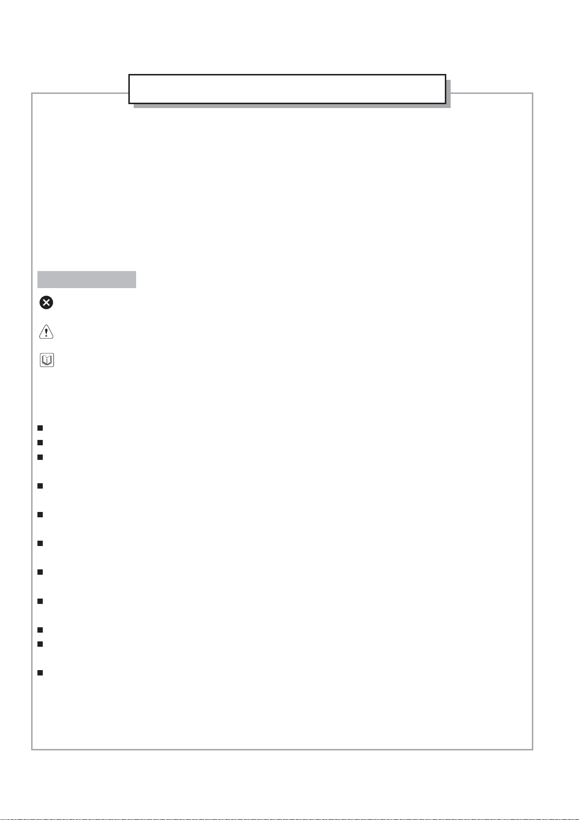
A WORD ABOUT SAFETY
1. Wear the appropriate safety equipment that is
necessary for the procedure being performed.
Safety glasses
Mask
Face shield
2. When welding or performing other procedures that
require the use of an open flame near the fuel tank,
disconnect and remove the tank and fuel pipe, and
cap the pipe to prevent fuel leakage.
Ear protectors
Gloves
Safety shoes
BVQGI6002
BVQGI6003
Page 5
GENERAL INFORMATION GI-3
WELDING PROCEDURES
Observe the following tips when welding.
1. Wear appropriate eye protection.
2. Carefully follow the manufacturers operating
instructions for the welding machine you are using.
3. Do not weld, smoke or allow open flames around
volatile chemicals, cleaners or solvents or in any area
where they have just been used.
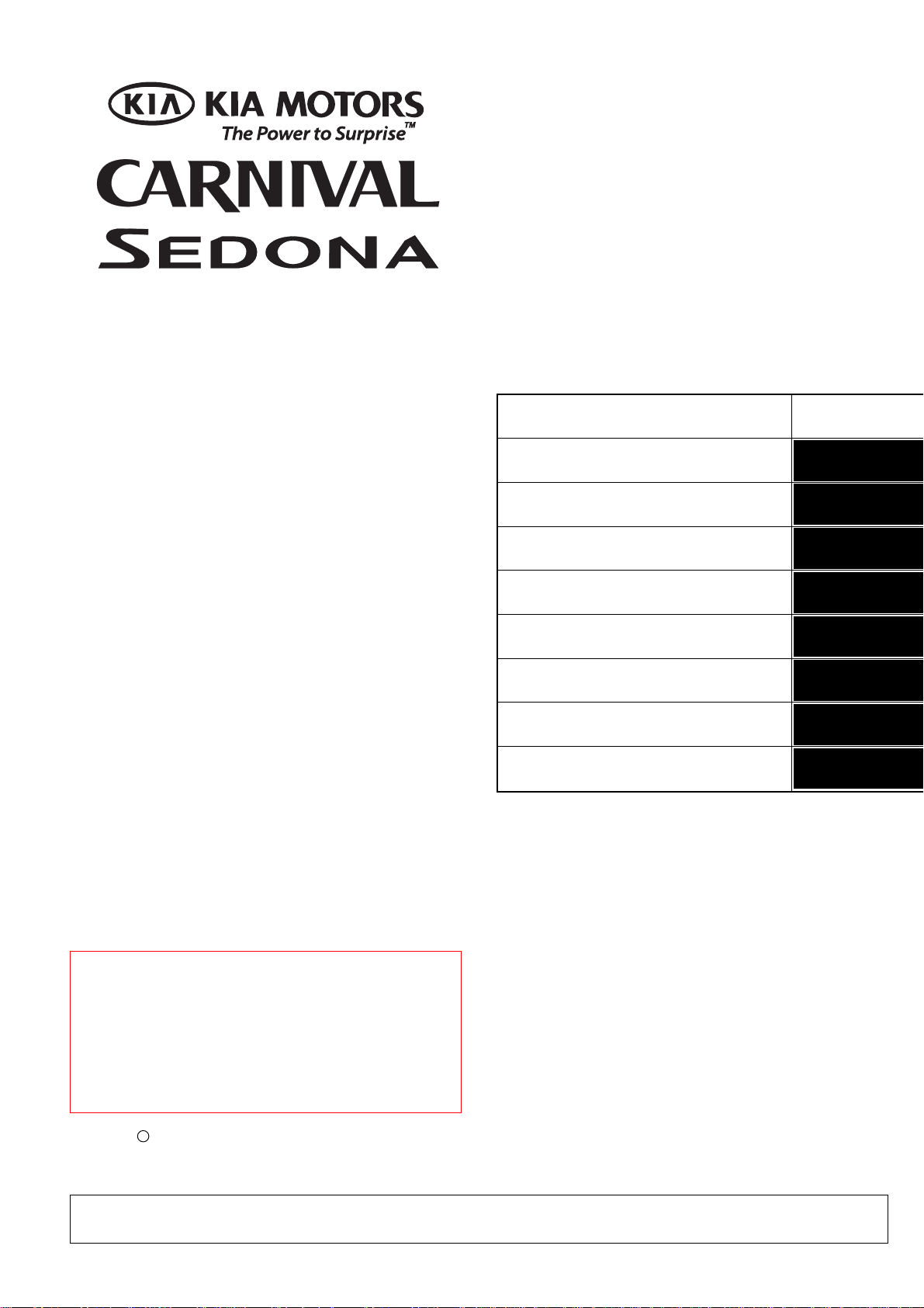
BODY FRAME STRAIGHTENER
When using a frame straightener, do not enter the area
where the body is being straightened by the chain.
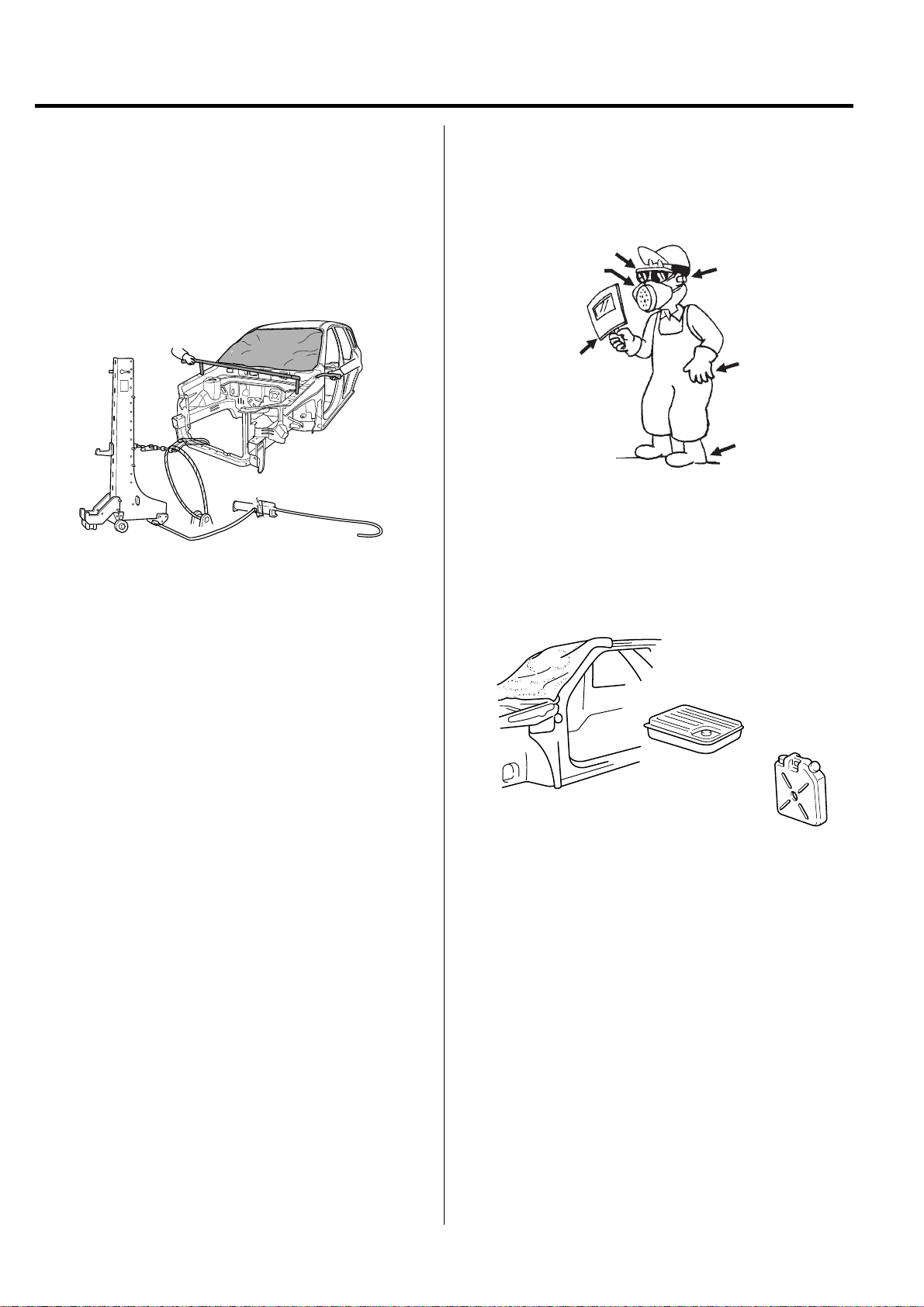
ELECTRICAL PROCEDURES
1. Disconnect the negative battery terminal.
2. Do not pull on wires when disconnecting electrical
connectors. Be careful to hold the connector itself when
disconnecting it.
3. Insert the connector until it "licks" when connecting
the connector.
4. Handle all electrical components with care.
BVQGI6004
Page 6
GI-4 GENERAL INFORMATION
FOR BEST RESUL TS
DISASSEMBLY
Measuring dimensions before beginning
Measure the dimensions of the damaged area according to the body dimension drawings before disassembling and repairing.
Adjust dimensions with body frame adjuster if deformed.
Selecting cutting area
Select a cutting area that is easily accessible and that is prone to the least amount of distortion when welding.
Select an area that would allow the new part to overlap repair area by 1.2~2.0 in (30~50 mm).
Protecting body from damage
Secure the body with clamps and jacks to prevent damage to the body when working on it.
BVQGI6005
Page 7
GENERAL INFORMATION GI-5
Disassembling related parts
Use caution when removing body molding and trim from
the area to be worked.
Apply masking tape where needed to prevent damage to
the part being removed or to the vehicle body.
Before starting repairs, check if pipes, hoses or electrical
components are present near damaged area.
Wire harness
Repair work area
Cutting area
BVQGI6006
Page 8

GI-6 GENERAL INFORMATION
PREPARATION OF ASSEMBLY
Applying spot sealer
Remove paint from the surf ace of new parts and body to be spot welded, and apply spot sealer for rustproofing.
Selecting a welding method
If the thickness of the area to be welded with the panels overlapped is greater than 0.1 in (3 mm), do plug welding using a
carbon arc welding machine.
Protecting body from damage
Secure the body with clamps and jacks to prevent damage to the body when working on it.
Thicker than
0.1 in (3mm)
Machining holes for plug welding
Drill a hole of approximately 0.2~0.24 in (5~6 mm) in
diameter in those areas which are not suitable for spot
welding.
BVQGI6008
BVQGI6007
Adjusting a new part
The new part should be cut larger than the repair area,
overlapping the repair area by 1.2~2.0 in (30~50 mm).
1.2~2.0 in
(30~50 mm)
Overlap
body side to modify
new part to modify
1.2~2.0 in
(30~50 mm)
Overlap
BVQGI6009
Page 9
GENERAL INFORMATION GI-7
ASSEMBLY
Measuring dimensions before welding
When assembling a new part, assemble it according to the body dimensions given in Section 31, and start welding after
checking the gaps with nearby parts.
Caution when welding
The number of welding points should be determined based on the criteria below:
Spot welding Plug welding
Increase the number of
spot welds by 30%.
Pitch:
2.0 in (50 mm)
Old part
Pitch:
1.4 in (35 mm)
Repair part
Pitch: Same number of
welds as original part.
Repair part
more than
0.1 in (3 mm)
BVQGI6010
Caution when spot welding
The tip of the spot welding machine should be maintained to a minimum of 0.1 in (3 mm) because it greatly affects welding
strength. When possible , spot welding should be done between the existing spot welded points .
Before and after spot welding, weld a test piece(test pin) of the same material as the body panel, and check the welding
strength.
0.1 in
(3 mm)
Good
No good
Using a hammer and a chisel
Existing welded spots
New welded spots
0.1 in
(3 mm)
Center
diameter
Using a test piece(test pin)
Nugget diameter
to be 4/5 of chip
diameter
BVQGI6011
Page 10
GI-8 GENERAL INFORMATION
RUSTPROOF TREATMENT AFTER ASSEMBLY
Body sealing
Apply body sealer where necessary.
Applying rustproof material
Apply rustproofing material(wax, oil, etc.) behind welded area.
Applying undercoat
Apply undercoat on the body where necessary .
BVQGI6012
Page 11
GENERAL INFORMATION GI-9
VEHICLE LIFT (2-SUPPORT TYPE) AND SAFETY STAND POSITIONS
1. Place the lift blocks under the support points as shown in the illustration
2. Raise the hoist a few inches and rock the v ehicle to be sure it is firmly supported.
3. Raise the hoist to full height to inspect the lift points for secure support.
Lift Block
Lift Block
[Front]
[Rear]
BVQGI6013
Page 12
GI-10 GENERAL INFORMATION
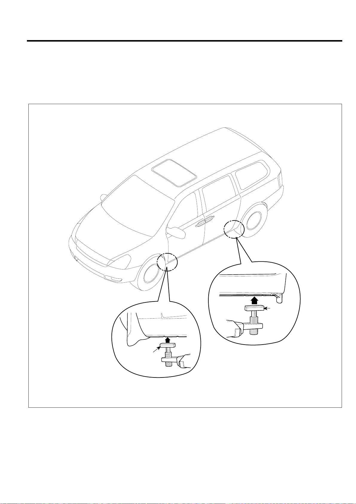
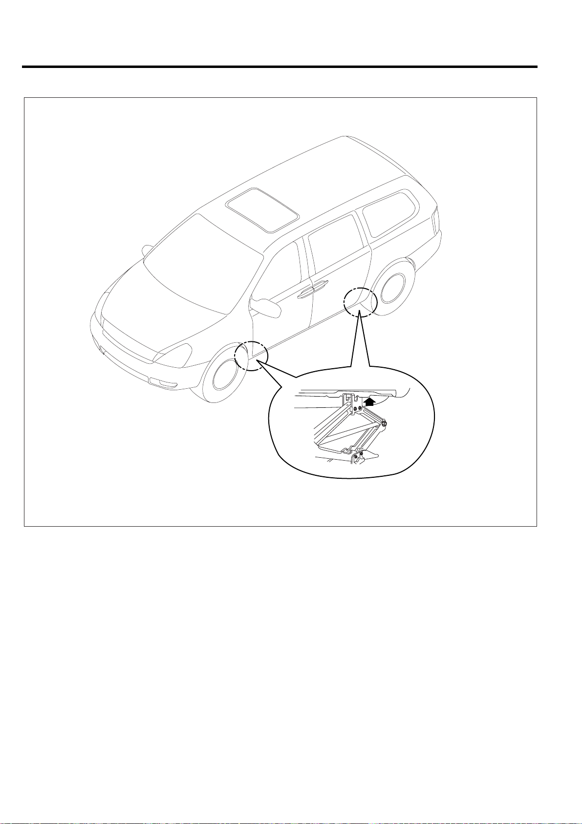
JACK SUPPORT POSITIONS
BVQGI6014
Page 13
GENERAL INFORMATION GI-11
BODY COLORS AND MAJOR SPECIFICATIONS
KIA COLOR CODES
Kia code Paint color
7P
J9
K5
K9
6C
7V
9B
U4
UD
PAINT MANUFACTURE CODES
Kia code
Color name Dupont
Spies
Hecker
Cherry Kiss Cocktail
Evening Sailing Gold
V elvet Indigo Blue
Crystal Blue
Clear Silver
Olive Gray
Midnight Black
White Pearl
Clear White
Standox BASF
Akzo
Nobel
PPG
7P
J9
K5
K9
6C
7V
9B
U4
UD
Cherry Kiss Cocktail
Evening Sailing Gold
V elvet Indigo Blue
Crystal Blue
Clear Silver
Olive Gray
Midnight Black
White Pearl
Clear White
X3089
X3088
X3090
X3091
X1135
X2188
M0510
M7817
F2756
769042
769041
769043
769044
746556
760711
75343
744249
755719
7P
J9
K5
K9
6C
7V
9B
U4
UD
7P
J9
K5
K9
6C
7V
9B
U4
UD
KIA9322
KIA9106
KIA9546
KIA9545
KIA9742
KIA9741
KIA9411
KIA9405
KIA4004
7P
J9
K5
K9
6C
7V
9B
U4
UD
Page 14

Body
Construction
BODY COMPONENTS .................................BC - 2
ZINC-GALVANIZED STEEL PANELS ....BC - 4
HIGH STRENGTH STEEL PANELS .......BC - 6
BC
Page 15
BC-2 BODY CONSTRUCTION
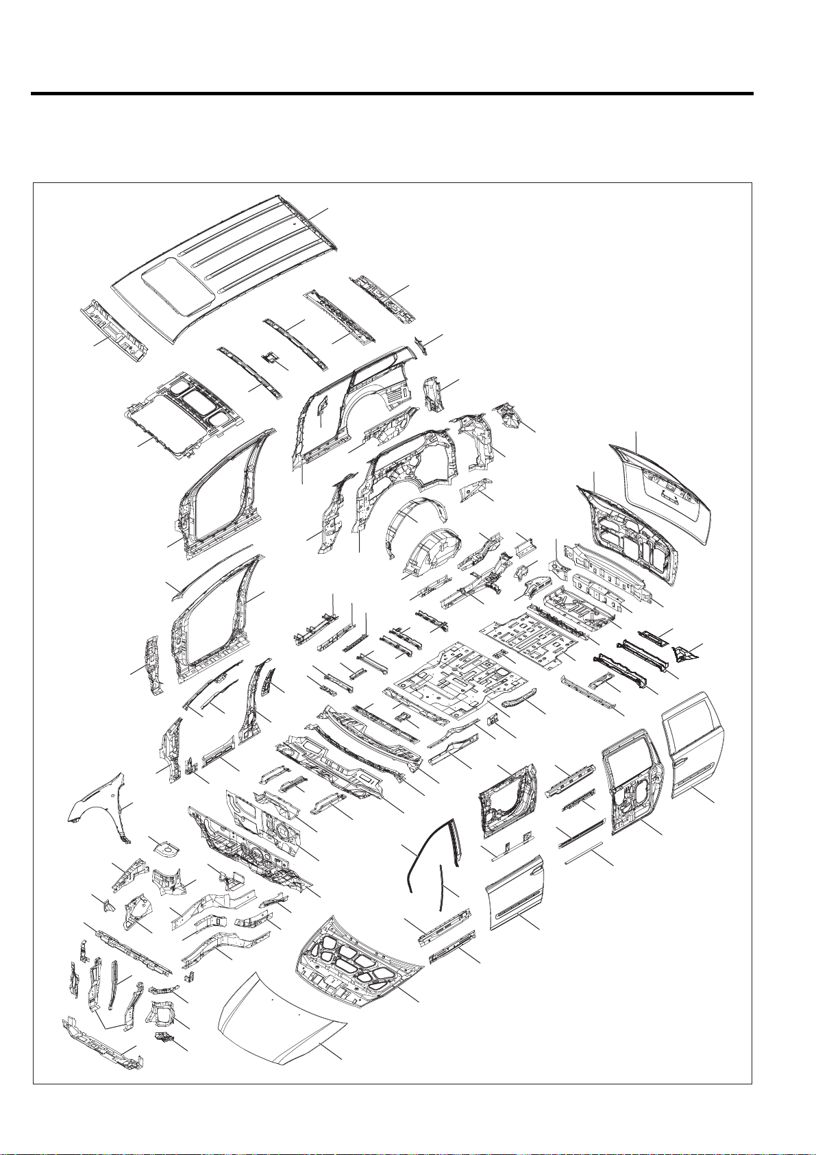
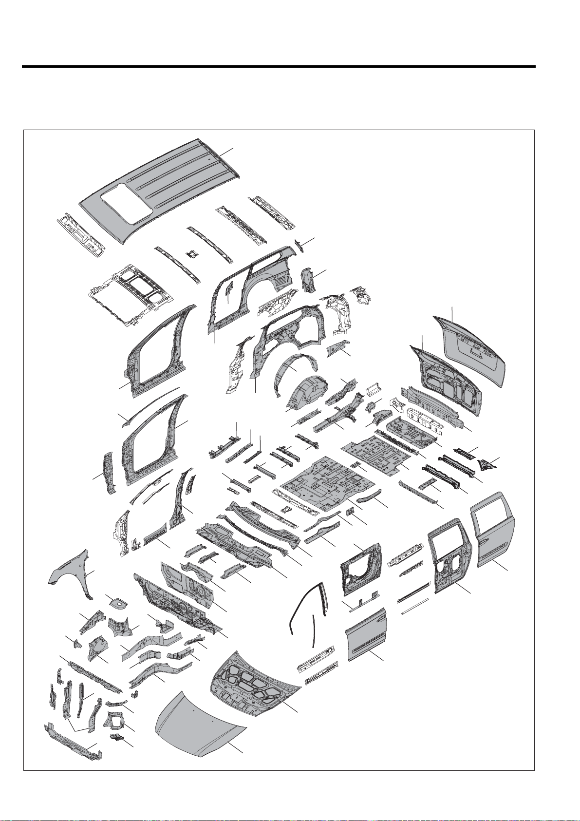
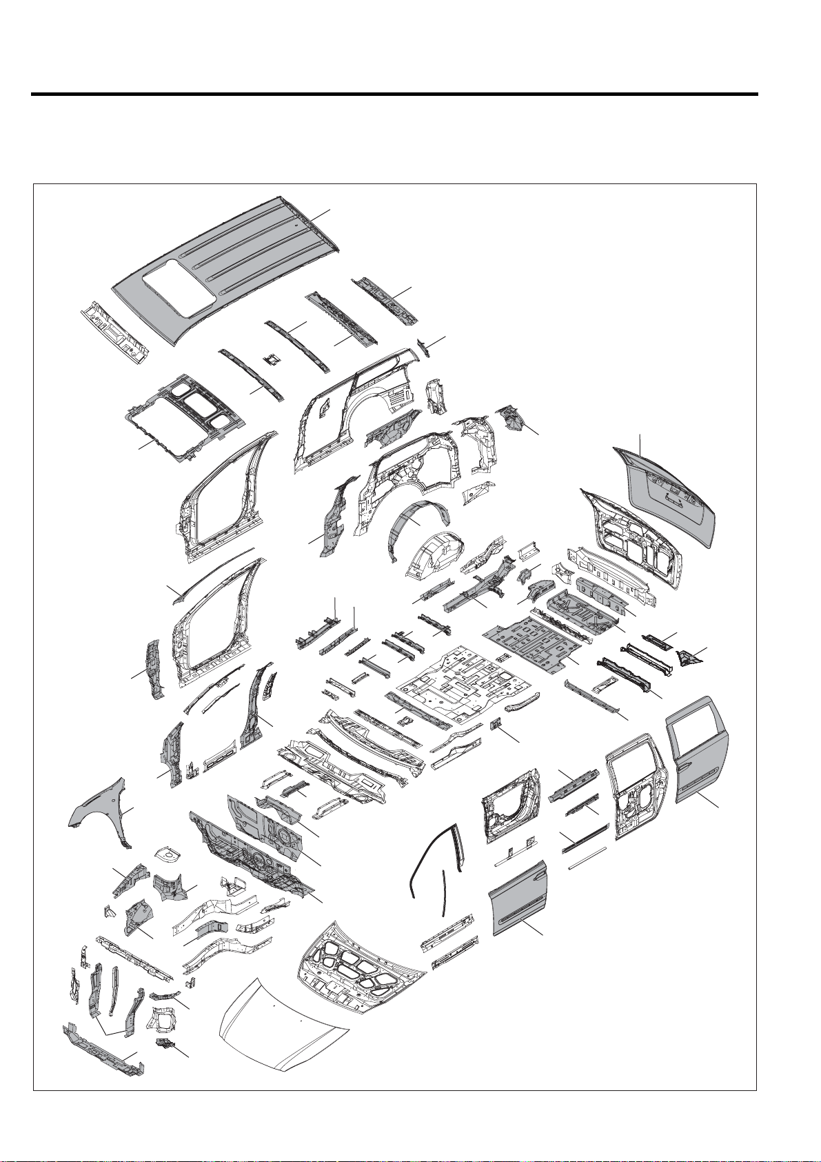
BOD Y COMPONENTS
Body construction will sometimes differ depending on specifications and country of destination. Theref ore, please k eep in
mind that the information contained herein is based on vehicles for general destination.
61
67
64
111
62
66
17
65
63
107
68
105
108
109
90
92
72
16
14
22
6
13
20
7
95
23
15
91
110
94
93
96
21
19
106
97
32
33
18
12
10
100
101
99
30
11
31
102
52
37
38
35
36
25
26
71
81
79
29
34
9
8
27
70
69
112
78
77
40
76
80
50
103
5153
46
39
98
24
28
41
104
45
84
86
75
42
60
43
89
85
44
87
49
47
48
88
59
58
56
57
55
54
82
83
1
4
5
2
3
73
74
BVQBC6001
Page 16

BODY CONSTRUCTION BC-3
1. Radiator support side member assembly
2. Head lamp support panel
3. Fender mounting braket assembly
4. Radiator support side member assembly
5. Radiator support lower outer member assembly
6. Radiator upper center member assembly
7. Radiator center stay member assembly
8. Dash panel assembly
9. Dash rainforcement assembly
10. Dash lower member assembly
11. Dash lower outer member assembly
12. Dash lower outer center member assembly
13. Fender apron inner lower panel assembly
14. Fender apron inner upper panel assembly
15. Front shock absorber housing panel assembly
16. Front shock absorber housing upper panel
17. Fender apron inner front support
18. Engine mounting bracket assembly
19. Front side inner member assembly
20. Front side member inner reinforcement assembly
21. Front side member inner rear reinforcement assembly
22. Front side member outer member assembly
23. Side cross front member
24. Center floor panel
25. Front seat cross front member assembly
26. Front seat cross rear member assembly
27. Console mounting front bracket assembly
28. Console mounting rear bracket assembly
29. Center floor side member
30. Center floor side member reinforcement assembly
31. Center floor side member upper reinforcement
32. No.1 cross member reinforcement
33. No.1 cross member reinforcement
34. No.1 cross member support reinforcement
35. No.1 cross member assembly
36. No.3 cross member assembly
37. No.3 cross member assembly
38. No.3 cross member assembly
39. Side sill inner upper panel
40. Side sill inner lower panel
41. Side sill inner rear panel
42. Rail guide lower panel assembly
43. Rear floor panel
44. Rear floor extension assembly
45. Rear floor side reinforcement
46. Rear floor side panel assembly
47. Rear floor rear panel
48. Rear floor rear cross member assembly
49. Rear towing hook bracket assembly
50. Rear floor side member
51. Rear floor side member extension assembly
52. Rear floor side front reinforcement assembly
53. Rear floor side rear reinforcement assembly
54. No.4 cross member assembly
55. No.5 cross member assembly
56. No.6 cross member
57. No.6 cross gusset
58. Back panel
59. Rear transverse member
60. Rear transverse side member
61. Roof panel
62. Roof front lower rail assembly
63. Roof No.2 rail
64. Roof No.2 rail
65. Room lamp mounting bracket
66. Roof rear upper rail assembly
67 Roof rear lower rail
68. Sun roof rack front bracket assembly
69. Cowl top outer panel
70. Cowl top outer reinforcement
71. Cowl inner lower panel assembly
72. Fender panel
73. Hood outer panel
74. Hood inner panel
75. Front door outer panel
76. Front door inner panel
77. Front door quadrant channel
78. Front door reinforcement beam
79. Front door belt outer rail
80. Front door belt inner rail
81. Front door frame assembly
82. Rear door outer panel
83. Rear door inner panel
84. Rear door belt outer rail
85. Rear door belt inner rail assembly
86. Rear door outer rail
87. Rear door beam
88. Tail gate outer panel
89. Tail gate inner panel
90. Front inner upper pillar assembly
91. Side inner upper reinforcement assembly
92. Front inner lower pillar assembly
93. Center pillar inner panel assembly
94. Front seatbelt upper mounting bracket assembly
95. Front pillar inner lower reinforcement assembly
96. Sill side outer front reinforcement
97. Quarter inner front reinforcement
98. Rear side belt upper mounting reinforcement assembly
99. Quarter inner panel
100. Quarter inner belt reinforcement assembly
101. Wheel house outer panel
102. Rear wheel house inner panel assembly
103. Quarter inner rear lower extension assembly
104. D pillar reinforcement gusset assembly
105. Front side outer panel
106. Front side outer panel
107. Fender rear upper reinforcement
108. Front pillar outer upper reinforcement
109. Front pillar outer lower reinforcement
110. Front side outer panel
111. Quarter outer rear upper extension
112. Rear combination lamp housing panel
Page 17
BC-4 BODY CONSTRUCTION
ZINC-GAL VANIZED STEEL PANELS
Becavanized steel panel has excellent resistance, it tis used in areas which have a high possibility of painting deficiency
below.
61
111
112
17
44
47
49
88
58
56
57
55
54
48
82
83
107
89
106
103
101
105
108
109
72
16
14
6
7
13
23
15
22
20
110
32
93
96
12
18
21
19
10
99
30
11
31
102
52
37
38
35
36
71
29
9
8
70
69
53
78
40
76
50
39
46
24
28
41
45
43
42
75
1
4
5
2
3
73
74
BVQBC6002
Page 18

BODY CONSTRUCTION BC-5
1. Radiator support side member assembly
2. Head lamp support panel
3. Fender mounting braket assembly
4. Radiator support side member assembly
5. Radiator support lower outer member assembly
6. Radiator upper center member assembly
7. Radiator center stay member assembly
8. Dash panel assembly
9. Dash rainforcement assembly
10. Dash lower member assembly
11. Dash lower outer member assembly
12. Dash lower outer center member assembly
13. Fender apron inner lower panel assembly
14. Fender apron inner upper panel assembly
15. Front shock absorber housing panel assembly
16. Front shock absorber housing upper panel
17. Fender apron inner front support
18. Engine mounting bracket assembly
19. Front side inner member assembly
20. Front side member inner reinforcement assembly
21. Front side member inner rear reinforcement assembly
22. Front side member outer member assembly
23. Side cross front member
24. Center floor panel
25. Front seat cross front member assembly
26. Front seat cross rear member assembly
27. Console mounting front bracket assembly
28. Console mounting rear bracket assembly
29. Center floor side member
30. Center floor side member reinforcement assembly
31. Center floor side member upper reinforcement
32. No.1 cross member reinforcement
33. No.1 cross member reinforcement
34. No.1 cross member support reinforcement
35. No.1 cross member assembly
36. No.3 cross member assembly
37. No.3 cross member assembly
38. No.3 cross member assembly
39. Side sill inner upper panel
40. Side sill inner lower panel
41. Side sill inner rear panel
42. Rail guide lower panel assembly
43. Rear floor panel
44. Rear floor extension assembly
45. Rear floor side reinforcement
46. Rear floor side panel assembly
47. Rear floor rear panel
48. Rear floor rear cross member assembly
49. Rear towing hook bracket assembly
50. Rear floor side member
51. Rear floor side member extension assembly
52. Rear floor side front reinforcement assembly
53. Rear floor side rear reinforcement assembly
54. No.4 cross member assembly
55. No.5 cross member assembly
56. No.6 cross member
57. No.6 cross gusset
58. Back panel
59. Rear transverse member
60. Rear transverse side member
61. Roof panel
62. Roof front lower rail assembly
63. Roof No.2 rail
64. Roof No.2 rail
65. Room lamp mounting bracket
66. Roof rear upper rail assembly
67 Roof rear lower rail
68. Sun roof rack front bracket assembly
69. Cowl top outer panel
70. Cowl top outer reinforcement
71. Cowl inner lower panel assembly
72. Fender panel
73. Hood outer panel
74. Hood inner panel
75. Front door outer panel
76. Front door inner panel
77. Front door quadrant channel
78. Front door reinforcement beam
79. Front door belt outer rail
80. Front door belt inner rail
81. Front door frame assembly
82. Rear door outer panel
83. Rear door inner panel
84. Rear door belt outer rail
85. Rear door belt inner rail assembly
86. Rear door outer rail
87. Rear door beam
88. Tail gate outer panel
89. Tail gate inner panel
90. Front inner upper pillar assembly
91. Side inner upper reinforcement assembly
92. Front inner lower pillar assembly
93. Center pillar inner panel assembly
94. Front seatbelt upper mounting bracket assembly
95. Front pillar inner lower reinforcement assembly
96. Sill side outer front reinforcement
97. Quarter inner front reinforcement
98. Rear side belt upper mounting reinforcement assembly
99. Quarter inner panel
100. Quarter inner belt reinforcement assembly
101. Wheel house outer panel
102. Rear wheel house inner panel assembly
103. Quarter inner rear lower extension assembly
104. D pillar reinforcement gusset assembly
105. Front side outer panel
106. Front side outer panel
107. Fender rear upper reinforcement
108. Front pillar outer upper reinforcement
109. Front pillar outer lower reinforcement
110. Front side outer panel
111. Quarter outer rear upper extension
112. Rear combination lamp housing panel
Page 19
BC-6 BODY CONSTRUCTION
HIGH STRENGTH STEEL P ANELS
Because high strength steel panel has excellent resistance, it is used in areas which have a high posibility of painting
deficiency below .
61
67
64
111
66
63
14
109
68
72
92
108
15
93
97
12
10
85
47
48
88
59
56
57
54
82
104
101
45
29
30
9
35
26
36
52
37
38
50
46
43
41
84
86
8
13
20
1
4
5
3
75
BVQBC6003
Page 20

BODY CONSTRUCTION BC-7
1. Radiator support side member assembly
2. Head lamp support panel
3. Fender mounting braket assembly
4. Radiator support side member assembly
5. Radiator support lower outer member assembly
6. Radiator upper center member assembly
7. Radiator center stay member assembly
8. Dash panel assembly
9. Dash rainforcement assembly
10. Dash lower member assembly
11. Dash lower outer member assembly
12. Dash lower outer center member assembly
13. Fender apron inner lower panel assembly
14. Fender apron inner upper panel assembly
15. Front shock absorber housing panel assembly
16. Front shock absorber housing upper panel
17. Fender apron inner front support
18. Engine mounting bracket assembly
19. Front side inner member assembly
20. Front side member inner reinforcement assembly
21. Front side member inner rear reinforcement assembly
22. Front side member outer member assembly
23. Side cross front member
24. Center floor panel
25. Front seat cross front member assembly
26. Front seat cross rear member assembly
27. Console mounting front bracket assembly
28. Console mounting rear bracket assembly
29. Center floor side member
30. Center floor side member reinforcement assembly
31. Center floor side member upper reinforcement
32. No.1 cross member reinforcement
33. No.1 cross member reinforcement
34. No.1 cross member support reinforcement
35. No.1 cross member assembly
36. No.3 cross member assembly
37. No.3 cross member assembly
38. No.3 cross member assembly
39. Side sill inner upper panel
40. Side sill inner lower panel
41. Side sill inner rear panel
42. Rail guide lower panel assembly
43. Rear floor panel
44. Rear floor extension assembly
45. Rear floor side reinforcement
46. Rear floor side panel assembly
47. Rear floor rear panel
48. Rear floor rear cross member assembly
49. Rear towing hook bracket assembly
50. Rear floor side member
51. Rear floor side member extension assembly
52. Rear floor side front reinforcement assembly
53. Rear floor side rear reinforcement assembly
54. No.4 cross member assembly
55. No.5 cross member assembly
56. No.6 cross member
57. No.6 cross gusset
58. Back panel
59. Rear transverse member
60. Rear transverse side member
61. Roof panel
62. Roof front lower rail assembly
63. Roof No.2 rail
64. Roof No.2 rail
65. Room lamp mounting bracket
66. Roof rear upper rail assembly
67 Roof rear lower rail
68. Sun roof rack front bracket assembly
69. Cowl top outer panel
70. Cowl top outer reinforcement
71. Cowl inner lower panel assembly
72. Fender panel
73. Hood outer panel
74. Hood inner panel
75. Front door outer panel
76. Front door inner panel
77. Front door quadrant channel
78. Front door reinforcement beam
79. Front door belt outer rail
80. Front door belt inner rail
81. Front door frame assembly
82. Rear door outer panel
83. Rear door inner panel
84. Rear door belt outer rail
85. Rear door belt inner rail assembly
86. Rear door outer rail
87. Rear door beam
88. Tail gate outer panel
89. Tail gate inner panel
90. Front inner upper pillar assembly
91. Side inner upper reinforcement assembly
92. Front inner lower pillar assembly
93. Center pillar inner panel assembly
94. Front seatbelt upper mounting bracket assembly
95. Front pillar inner lower reinforcement assembly
96. Sill side outer front reinforcement
97. Quarter inner front reinforcement
98. Rear side belt upper mounting reinforcement assembly
99. Quarter inner panel
100. Quarter inner belt reinforcement assembly
101. Wheel house outer panel
102. Rear wheel house inner panel assembly
103. Quarter inner rear lower extension assembly
104. D pillar reinforcement gusset assembly
105. Front side outer panel
106. Front side outer panel
107. Fender rear upper reinforcement
108. Front pillar outer upper reinforcement
109. Front pillar outer lower reinforcement
110. Front side outer panel
111. Quarter outer rear upper extension
112. Rear combination lamp housing panel
Page 21

Body
Dimensions
GENERAL
MEASUREMENT METHOD .......................BD - 2
PROJECTED DIMENSIONS ............................BD - 2
ACTUAL-MEASUREMENT DIMENSIONS......BD - 3
MEASUREMENT POINT..................................BD - 3
FRONT BODY .................................................BD - 4
SIDE BODY (FRONT) ...................................BD - 6
SIDE BODY (REAR) .....................................BD - 8
INTERIOR A .....................................................BD - 10
INTERIOR B .....................................................BD - 12
INTERIOR C .....................................................BD - 14
REAR BODY ....................................................BD - 16
UNDER BODY
(PROJECTED DIMENSIONS)
UNDER BODY
(STRAIGHT-LINE DIMENSIONS)
.........................................................BD - 2
...................BD - 18
............BD - 21
BD
Page 22
BD-2 BODY DIMENSIONS
GENERAL
1. Basically, all measurements in this manual are taken
with a tracking gauge.
2. When a measuring tape is used, check to be sure
there is no elongation, twisting or bending.
3. For measuring dimensions, both projected dimension
and actual-measurement dimension are used in this
manual.
MEASUREMENT METHOD
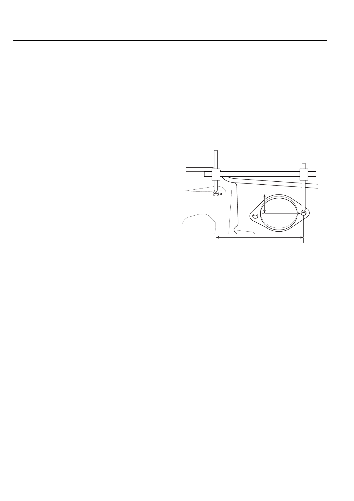
PROJECTED DIMENSIONS
1. These are the dimensions measured when the
measurement points are projected into the reference
plane, and are the reference dimensions used for body
alterations.
2. If the length of the tracking gauge probes are
adjustable, make the measurement by lengthening one
probe by the amount equivalent to the difference in
height of the two surfaces.
Height
Projected Dimension
BMCBD6001
Page 23
BODY DIMENSIONS BD-3
N
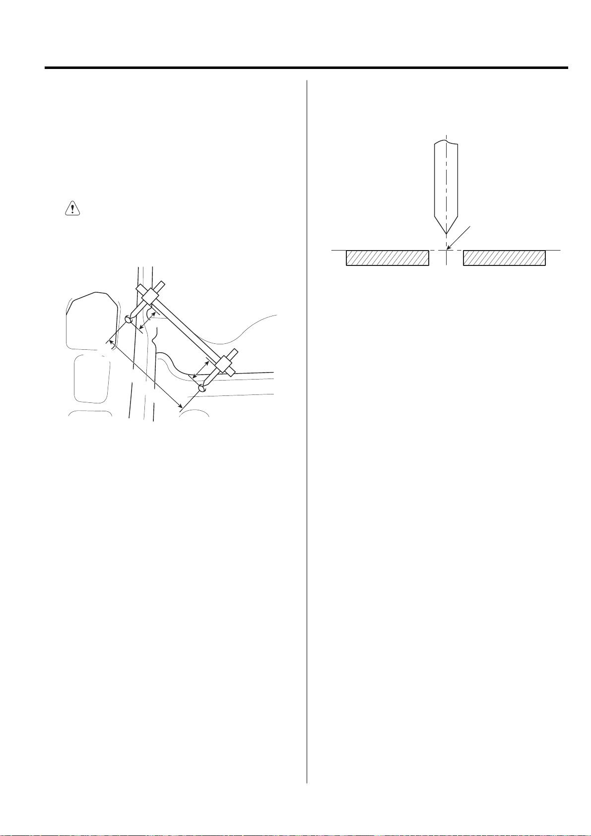
ACTUAL-MEASUREMENT DIMENSIONS
1. These dimensions indicate the actual linear distance
between measurement points, and are the reference
dimensions for use if a tracking gauge is used for
measurement.
2. Measure by first adjusting both probes to the same
length (A=A')
CAUTIO
Check the probes and gauge itself to make sure
there is no free play .
A
Actually-Measured Dimension
A'
MEASUREMENT POINT
1. Measurements should be taken at the hole center.
Hole Center
BMCBD6003
BMCBD6002
Page 24
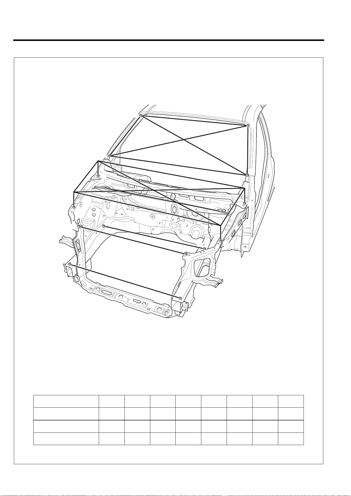
BD-4 BODY DIMENSIONS
FRONT BODY
H'
H
G'
A'
D'
B'
C'
F'
* These dimensions indicated in this figure are actual-measurement dimensions.
E'
E
C
F
D
B
G
A
BVQBD6100
Point symbol
Length(mm)
Point symbol
Length(mm)
A-A'
1660
G-G'
1552.1
A-B
584.4
H-H'
1273
A-B'
584.4
H-G
1562.5
B-B'
1484.8
H-G'
1562.5
C-C' D-D' E-E' F-F'
1071.1 1310.5 1104.1 1120
Page 25
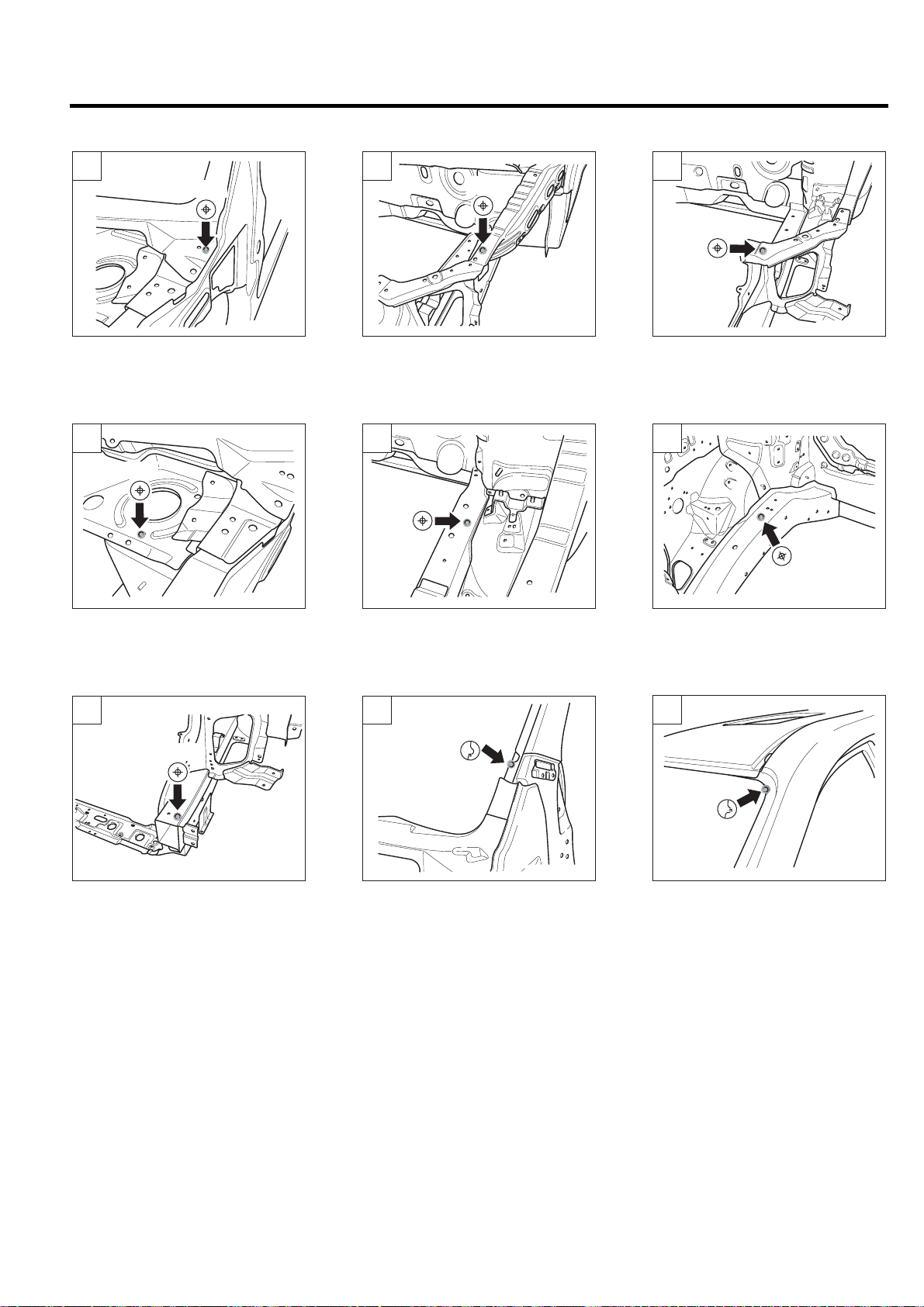
BODY DIMENSIONS BD-5
A
A,A'
BVQBD6101
Hood hinge mounting hole (ø12)
D
D,D'
BVQBD6104
B
B,B'
BVQBD6102
Fender mounting hole (ø8)
E
E
BVQBD6105
C
C,C'
BVQBD6103
Radiator upper member mounting
hole (ø8)
E'
E'
BVQBD6106
Front strut mounting hole (ø14)
F
F,F'
BVQBD6107
Front bumper bracket mounting
hole (ø9)
Transaxle bracket mounting hole
(ø12)
G
G,G'
BVQBD6108
Location notch
Engine bracket mounting hole
(ø18)
H
H,H'
BVQBD6109
Location notch
Page 26
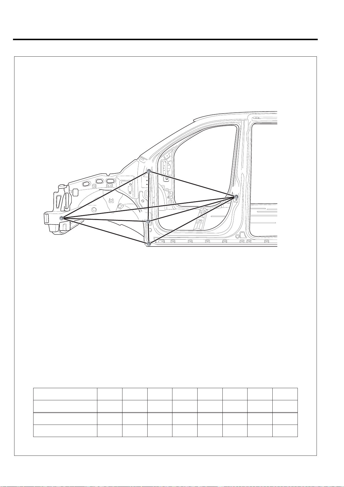
BD-6 BODY DIMENSIONS
SIDE BODY (FRONT)
B
E
A
* These dimensions indicated in this figure are actual-measurement dimensions.
C
D
BVQBD6200
Point symbol
Length(mm)
Point symbol
Length(mm)
A-B
1244.9
A-E
2079.4
A-C A-D B-C C-D B-E C-E D-E
1119.4 1119.0 536.4 301.7 1005.8 1005.8 1126.2
Page 27
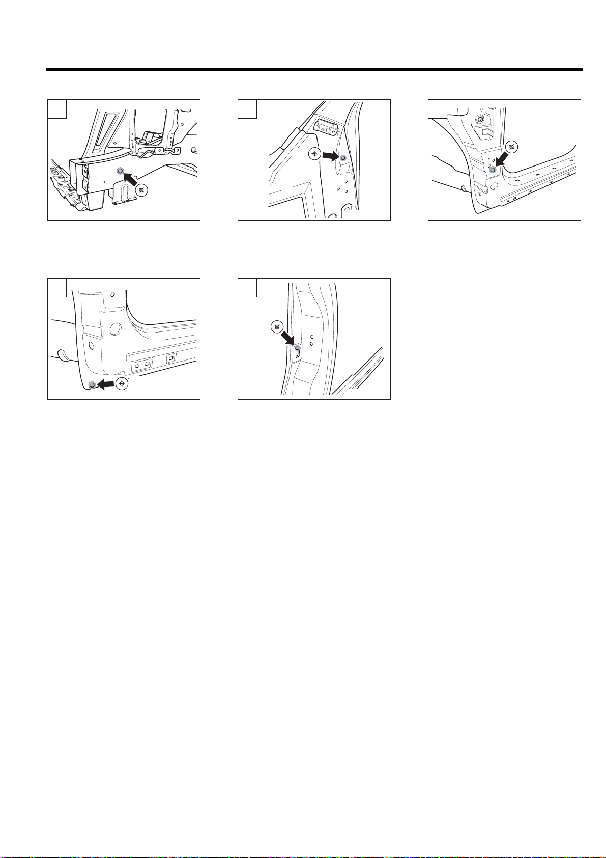
BODY DIMENSIONS BD-7
A
A
BVQBD6201
Tooling hole (ø16)
D
D
BVQBD6204
B
B
BVQBD6202
Front fender mounting hole (ø10)
E
E
BVQBD6205
C
C
BVQBD6203
Front door hinge mounting hole
(ø13)
Front fender mounting hole (ø10)
Front door switch mounting hole
(R9.2X9.2)
Page 28
BD-8 BODY DIMENSIONS
SIDE BODY (REAR)
A
B
C
F
G
H
D
K
E
BVQBD6300
* These dimensions indicated in this figure are actual-measurement dimensions.
Point symbol
Length(mm)
Point symbol
Length(mm)
Point symbol
Length(mm)
A-B
913.6
D-E
535.3
F-G
231.0
A-C
959.7
D-F
1151.5
A-D
1077
D-G
1153.1
A-E
1479.8
D-H
1327.6
B-C
1377.8
D-K
1353.2
B-D
968
E-H
1432
B-E
1000
E-K
1303.1
C-D
658.9
H-K
398.4
Page 29
BODY DIMENSIONS BD-9
A
A
BVQBD6301
Rear door stopper mounting hole
(ø10)
D
D
BVQBD6304
B
B
BVQBD6302
Rear door stopper mounting hole
(ø10)
E
E
BVQBD6305
C
C
BVQBD6303
Qurter glass guide mounting hole
(S6.2X8)
F
F
BVQBD6306
Rear door switch mounting hole
(ø8)
G
G
BVQBD6307
Qurter glass stopper mounting
hole (ø8.5)
Side garnish mounting hole
(R9X12)
H
H
BVQBD6308
Center rail cover mounting hole
(ø10)
Qurter glass stopper mounting
hole (ø8.5)
K
K
BVQBD6309
Rear bumper mounting hole (ø11)
Page 30
BD-10 BODY DIMENSIONS
INTERIOR A
C'
B'
A'
B
C
F'
D'
A
E'
D
E
F
H'
K'
G'
M'
G
N'
H
P'
K
M
N
P
BVQBD6400
* These dimensions indicated in this figure are actual-measurement dimensions.
Point symbol
Length(mm)
Point symbol
Length(mm)
A-A'
1315.9
K-K'
1639.5
B-B'
1525.9
M-M'
1106.0
C-C'
1550.0
N-N'
1293.0
D-D'
1279.7
P-P'
1317.1
E-E' F-F' G-G' H-H'
1572.0 1569.2 1291.2 1593.3
Page 31

BODY DIMENSIONS BD-11
A
A,A'
BVQBD6401
A pillar trim mounting hole (ø8.5)
D
D,D'
BVQBD6404
B
B,B'
BVQBD6402
Curtain airbag mounting hole
E
E,E'
BVQBD6405
C
C,C'
BVQBD6403
A pillar trim mounting hole (ø8.5)
(ø6.6)
F
F,F'
BVQBD6406
B pillar trim mounting hole (ø6.6)
G
G,G'
BVQBD6407
C pillar trim mounting hole (ø9)
M
M,M'
Paint stay mounting hole (ø11)
H
H,H'
Power sliding door module
mounting hole (ø9)
BVQBD6408
N
Seat belt mounting hole (ø12.4)
K
K,K'
BVQBD6409
Tooling hole (ø12)
P
BVQBD6410
D pillar trim mounting hole (ø8.5)
N
N'
BVQBD6411
Net hook mounting hole (ø9)
P,P'
BVQBD6412
Wire harness earth mounting
hole (ø9)
Page 32

BD-12 BODY DIMENSIONS
INTERIOR B
C'
B'
B
A'
C
F'
D'
A
E'
M'
M
D
E
F
H'
K'
G'
G
H
K
BVQBD6500
* These dimensions indicated in this figure are actual-measurement dimensions.
Point symbol
Length(mm)
Point symbol
Length(mm)
Point symbol
Length(mm)
M-A'
1482.6
M-K'
1555.2
M'-H
1632.0
M-B'
1539.7
M'-A
1482.6
M'-K
1511.7
M-C'
1350.8
M'-B
1539.7
M-D'
1417.6
M'-C
1350.8
M-E'
1207.5
M'-D
1417.6
M-F'
1010.6
M'-E
1207.5
M-G'
1807.2
M'-F
1010.6
M-H'
1649.3
M'-G
1807.2
Page 33

BODY DIMENSIONS BD-13
A
A,A'
BVQBD6401
A pillar trim mounting hole (ø8.5)
D
D,D'
BVQBD6404
B
B,B'
BVQBD6402
Curtain airbag mounting hole
E
E,E'
BVQBD6405
C
C,C'
BVQBD6403
A pillar trim mounting hole (ø8.5)
(ø6.6)
F
F,F'
BVQBD6406
B pillar trim mounting hole (ø6.6)
G
G,G'
BVQBD6407
C pillar trim mounting hole (ø9)
M
M'
Paint stay mounting hole (ø11)
H
H,H'
Power sliding door module
mounting hole (ø9)
BVQBD6408
Seat belt mounting hole (ø12.4)
K
K,K'
BVQBD6409
Tooling hole (ø12)
M
BVQBD6501
Seat mounting hole (ø14)
Page 34

BD-14 BODY DIMENSIONS
INTERIOR C
D'
E'
F'
* These dimensions indicated in this figure are actual-measurement dimensions.
D
G '
H
E
K
Q'
Q
F
G
M'
N'
H'
P'
K'
M
N
P
BVQBD6600
Point symbol
Length(mm)
Point symbol
Length(mm)
Point symbol
Length(mm)
Q-D'
1695.2
Q-P'
1641.4
Q'-N
1737.0
Q-E'
1579.8
Q'-D
1695.2
Q'-P
1637.9
Q-F'
1507.8
Q'-E
1579.8
Q-G'
1412.2
Q'-F
1507.8
Q-H'
1210.9
Q'-G
1412.2
Q-K'
1087.3
Q'-H
1192.4
Q-M'
1720.1
Q'-K
1084.7
Q-N'
1737.0
Q'-M
1720.1
Page 35

BODY DIMENSIONS BD-15
D
D,D'
BVQBD6404
B pillar trim mounting hole (ø6.6)
G
G,G'
BVQBD6407
E
E,E'
BVQBD6405
Paint stay mounting hole (ø11)
H
H,H'
BVQBD6408
F
F,F'
BVQBD6406
Seat belt mounting hole (ø12.4)
K
K,K'
BVQBD6409
C pillar trim mounting hole (ø9)
M
M,M'
BVQBD6410
D pillar trim mounting hole (ø8.5)
Q
Power sliding door module
mounting hole (ø9)
N
N
N'
BVQBD6411
Net hook mounting hole (ø9)
Tooling hole (ø12)
P
P,P'
BVQBD6412
Wire harness earth mounting
hole (ø9)
Q'
Q
BVQBD6601
Tooling hole (ø20)
Page 36

BD-16 BODY DIMENSIONS
REAR BOD Y
A
B
C
E E'
D
A'
B'
C'
D'
* These dimensions indicated in this figure are actual-measurement dimensions.
Point symbol
Length(mm)
Point symbol
Length(mm)
A-A'
820.0
C-B'
1391.0
B-B'
1174.7
C-D'
1565.1
BVQBD6700
C-C' D-D' E-E' B-E B-C' B-E'
1394.0 1464.0 976.0 994.4 1391.0 1461.3
Page 37

BODY DIMENSIONS BD-17
A
A,A'
BVQBD6701
Tail gate hinge mounting hole
D
D,D'
BVQBD6704
(ø12)
B
B,B'
BVQBD6702
Gas lift mounting hole (ø9)
E
E,E'
BVQBD6705
C
C,C'
BVQBD6703
Rear clamp mounting hole
(R8.5X8.5)
Rear bumper mounting hole (ø14)
Package trim mounting hole
(ø8.5)
Page 38

BD-18 BODY DIMENSIONS
UNDER BODY ( PROJECTED DIMENSIONS )
A
A'
B
B'
C
C'
E
E'
D
D'
F'
K
F
G
G'
H
H'
M
M'
N
N'
K'
R
Q
P
P'
Q'
R'
S
S'
0
AB C ED F G H
* These dimensions indicated in this figure are projected dimensions.
Point symbol
Length(mm)
Point symbol
Length(mm)
Point symbol
Length(mm)
Point symbol
Length(mm)
Point symbol
Length(mm)
Point symbol
A-A'
1095
K-K'
1325
O-B
-61.3
O-M
13.5
C-E
329.5
N-P
B-B'
1095
M-M'
959
O-C
78.1
O-N
-54.3
E-D
55
P-Q
C-C'
1048
N-N'
1097.5
O-D
-117.5
O-P
18
D-F
366.5
Q-R
D-D'
696
P-P'
840
O-E
-87.6
O-Q
81.5
F-G
972
R-S
KMNPQRS
BVQBD6800
E-E'
878
Q-Q'
1060
O-F
-85.8
O-R
26
G-H
415
F-F'
924.8
R-R'
1338
O-G
-31(LH)/-14(RH)
O-S
39.2
H-K
85
G-G'
1050
S-S'
1338
O-H
-15(LH)/0(RH)
A-B
138
K-M
605
H-H'
1066
O-A
-33.5
O-K
-1.4
B-C
631
M-N
164.5
Length(mm)
56
344.5
15
350
Page 39

BODY DIMENSIONS BD-19
A
A
BVQBD6801
Front stay mounting hole (ø13)
D
D
BVQBD6803
B
B
BVQBD6801A
Sub frame front mounting hole
(ø16)
E
E
BVQBD6803A
C
C
BVQBD6802
Brake pipe mounting hole (ø7)
F
F
BVQBD6804
Rear stay mounting hole (ø12)
G
G
BVQBD6805
Tooling hole (S22X20)
M
M
Sub frame rear mounting hole
(ø18)
H
H
BVQBD6806
Tooling hole (ø20)
N
N
Tooling hole (ø13)
K
K
BVQBD6806A
Traling arm mounting front hole
(ø14)
P
BVQBD6807
Sub frame mounting hole (ø18)
BVQBD6807A
Rear bumper stopper mounting
hole (ø11)
P
BVQBD6807B
Brake pipe bolt mounting hole
(ø16)
Page 40

BD-20 BODY DIMENSIONS
Q
Q
BVQBD6808
Tooling hole (S15X17)
R
R
BVQBD6808A
Tooling hole (S20X22)
S
S
BVQBD6809
Tooling hole (ø10)
Page 41

BODY DIMENSIONS BD-21
UNDER BOD Y ( A CTU AL-MEASUREMENT DIMENSIONS )
A
A'
C
C'
D'
R
D
F
F'
G
G'
H
H'
M
M'
R'
S
S'
BVQBD6900
* These dimensions indicated in this figure are actual-measurement dimensions.
Point symbol
Length(mm)
Point symbol
Length(mm)
Point symbol
Length(mm)
A-A'
1095
D'-H
2006.8
H-S'
2017.6
A-C'
1325.2
F-G'
1386.6
M-R'
1286.7
A'-D
1518.8
F'-H
1709.4
M'-S
1478
C-D'
1048.2
F'-M
2282.7
R-S'
1383.1
C'-F
1251.1
G-H'
1136.5
S-S'
1338
C'-G
2020.4
G'-M
1494
D-F'
973.1
H'-R
1749.1
D-G'
1650.5
H-M'
1225.3
Page 42

BD-22 BODY DIMENSIONS
A
A
BVQBD6801
Front stay mounting hole (ø13)
F
F
BVQBD6804
C
C
BVQBD6802
Brake pipe mounting hole (ø7)
G
G
BVQBD6805
D
D
BVQBD6803
Rear stay mounting hole (ø12)
H
H
BVQBD6806
Tooling hole (ø13)
M
M
BVQBD6807
Sub frame mounting hole (ø18)
Tooling hole (S22X20)
R
R
BVQBD6808A
Tooling hole (S20X22)
Tooling hole (ø20)
S
S
BVQBD6809
Tooling hole (ø10)
Page 43

BODY DIMENSIONS BD-23
Page 44

Body Panel Repair
Procedure
REPLACING BODY PANELS
CODES FOR REMOVING AND
INSTALLING BODY PANELS...........................BP - 2
NOTES WHEN WELDING BODY
REMOVING SPOT WELDED AREA ................BP - 3
INSTALLING A NEW BODY FRAME................BP - 5
DETERMINING A WELDING METHOD...........BP - 5
SPOT WELDING ..............................................BP - 5
CARBON ARC WELDING ...............................BP - 6
REPLACING BODY PANEL
REMOVAL...................................................BP - 7
PREPARATION FOR INSTALLATION ........BP - 9
INSTALLATION ...........................................BP - 10
RADIATOR SUPPORT PANEL
ASSEMBLY.......................................................BP - 12
REMOVAL ........................................................BP - 12
INSTALLATION.................................................BP - 14
COWL SIDE OUTER PANEL
REMOVAL ........................................................BP - 15
INSTALLATION.................................................BP - 16
FENDER APRON INNER LOWER PANEL
REMOVAL ........................................................BP - 17
INSTALLATION.................................................BP - 18
QUARTER PANEL
REMOVAL ........................................................BP - 35
INSTALLATION.................................................BP - 37
REAR FLOOR SIDE MEMBER
REMOVAL ........................................................BP - 38
INSTALLATION.................................................BP - 40
REAR COMBINATION LAMP HOUSING
PANEL
RREMOVAL......................................................BP - 42
INSTALLATION.................................................BP - 43
BACK PANEL
REMOVAL ........................................................BP - 44
INSTALLATION.................................................BP - 45
BP
FENDER APRON INNER UPPER PANEL
REMOVAL ........................................................BP - 19
INSTALLATION.................................................BP - 20
FRONT SIDE MEMBER...............................BP - 21
REMOVAL ........................................................BP - 22
INSTALLATION.................................................BP - 23
FRONT PILLAR
REMOVAL ........................................................BP - 25
INSTALLATION.................................................BP - 28
CENTER PILLAR
REMOVAL ........................................................BP - 31
INSTALLATION.................................................BP - 33
Page 45

BP-2 BODY PANEL REPAIR PROCEDURE
REPLACING BOD Y PANELS
CODES FOR REMOVING AND INSTALLING BODY PANELS
0.8~1.2 in.
(20~30 mm)
0.8~1.2 in.
(20~30 mm)
Rough cutting location
Location for cut and assembly
BVQBP6001
Page 46

BODY PANEL REPAIR PROCEDURE BP-3
NOTES WHEN WELDING BOD Y
REMOVING SPOT WELDED AREA
Most body parts are spot welded. In order to remov e the damaged area, it is best to remov e the spot welded area from the
body frame using a spot cutter or candle type edge drill bit.
Do not use a drill bit with a tapered edge. Center punch middle of spot weld to insure the entire spot weld will be removed.
1. Spot cutter 1. Drill(candle type edge) 1. Drill(taper edge)
2. 2. 2.
3. 3. 3.
Correct
Correct
Not correct
BVQBP6002
Page 47

BP-4 BODY PANEL REPAIR PROCEDURE
Center punch the middle(nugget) of the spot weld. Otherwise,
This part will not be cut. This part will be cut.
Spot welded area can be removed from the body frame. Spot welded area cannot be removed from the body
frame.
BVQBP6003
Page 48

BODY PANEL REPAIR PROCEDURE BP-5
INSTALLING A NEW BODY FRAME
The efficiency of the transmission and load distribution are determined by many complicated factors such as thickness of
plate, shape and size of a cross section, damage of parts, variance of joints, welding method, and/or welding locations.
Therefore, a new part should be fitted to the body frame using the proper procedures to avoid reducing the strength of the
body.
DETERMINING A WELDING METHOD
It is extremely important that appropriate welding methods, which don't reduce the original strength and durability of the body
be used when making repairs, Try to use either spot welding or carbon arc(plug) welding, Do not braze any body components
other than the ones brazed at the factory. Do not use an o xy-acetylene torch f or welding.
Welding Symbol Details
Spot welding
Carbon arc welding
(Plug welding)
Oxygen-acetylene welding
The most reliable welding method
(provides high efficiency and quality of assembled part.)
Use when spot welding cannot be done or spot welding is not necessary.
Not used
SPOT WELDING
1. Commercial spot welding machines do not perform as
well as the machines used in the manufacturing
process. When spot welding, increase the number of
spot welds by 30% (1.3 times the original number of
welds).
BVQBP6004
2. When spot welding, weld in the middle of the joint.
Good
BVQBP6006
BVQBP6005
• Spot welding on the edge of the joint will reduce welding
strength.
No good
BVQBP6007
Page 49

BP-6 BODY PANEL REPAIR PROCEDURE
CARBON ARC WELDING
In areas where spot welding is not suitable, do plug welding
using a carbon are welding machine.
1. Clamp the parts to be welded together tightly . Do not
exceed 1 mm of space between parts. A tolerance
greater than 1 mm will reduce the strength of the
welded area.
1mm
Maximum
tolerance
BVQBP6008
b) Do not weld on the edge of the flange joint.
No good
BVQBP6009
2. Weld in the middle of the flange joint.
a) Drill a hole 5~6 mm on one side of the flange only,
and weld within the hole.
Good
BVQBP6006
Page 50

BODY PANEL REPAIR PROCEDURE BP-7
REPLACING BODY PANEL
REMOVAL
1. Body measurement
a) Before removing, measure the damaged area
according to the dimensions supplied in Body
Dimension, section 31. If deformation is present,
use a frame straightener to adjust.
b) When removing a panel, apply clamps to prevent
damage of each part, and support the lower end
of the frame to prevent deformation during the
procedure.
Tracking gauge
3. Cutting rough area for replacement part
Cutting should be done according to the following steps
to make removal easy:
a) Use care when cutting an area close to a pipe or
wiring harness.
b) Cut an area leaving 30~50 mm of tolerance.
BVQBP6012
4. Removing paint from an area to be spot welded
Using a torch and wire brush, remove paint completely
before beginning welding.
2. Cut and welding point selection
Cutting, if necessary, should not be done in a
reinforcement area. Select an area which will result in
the least amount of deformation after welding.
Cut area
Reinforcement
Reinforcement
BVQBP6010
BVQBP6013
BVQBP6011
Page 51

BP-8 BODY PANEL REPAIR PROCEDURE
5 . Determine a cutting method
a) Cutting a spot welded area
Make a hole in the middle of spot welded area
with a punch, remove welded area using a spot
cutter and remove using a chisel.
BVQBP6014
b) Removing brazed area
Remove using a torch and wire brush, and chisel.
c) Removing arc welded area
Remove plug welded area using a disk grinder
and chisel.
BVQBP6015
BVQBP6016
Page 52

BODY PANEL REPAIR PROCEDURE BP-9
E
PREPARATION FOR INSTALLATION
1. Spot weld finish
Use a disk grinder or similar tool to finish spot weld
mark, Do not grind more than is necessary to smooth
surface.
2. Panel preparation
Repair any bent or uneven areas with a hammer to
improve the installation process.
BVQBP6017
4 . Preparation for spot welding
Remove paint on spot welded area and on the area
overlapped by the new part using a belt sander or similar
tool.
BVQBP6020
5. Drilling a hole for plug welding
If the thickness of the part to be welded is less than 3
mm, drill a 5~6 mm diameter hole. If the thickness of
the part to be welded is greater than 3 mm, drill a hole
using a 7 mm diameter drill.
3. Cutting a rough area for a new part
When rough cutting an area for a new part, leave a
tolerance of 30~50 mm.
NOT
Do not spot weld where thickness is greater than
3 mm.
BVQBP6018
BVQBP6021
BVQBP6019
Page 53

BP-10 BODY PANEL REPAIR PROCEDURE
E
INSTALLATION
1. Checking welding and fitting in advance
a) When installing a new part, measure the
dimensions of each part according to the body
dimensions given in Section 31, and set part to
the reference dimensions.
b) Prior to final welding, check the fit of all related
parts.
BVQBP6022
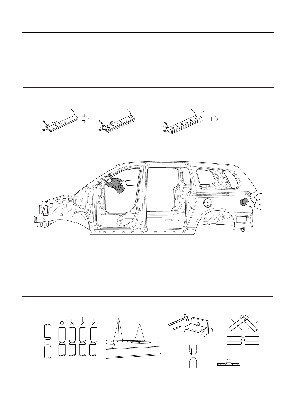
2. Selecting number of welding points
Spot welding : Multiply the original number of
factory welds by 1.3 times
Plug welding : Same number as original number
of factory welds
NOT
• Plug welding should be done using a carbon arc
welding machine.
• Brazing should be done only on areas that were
originally brazed at the factory .
Initial welding
pitch:50 mm
Spot welding:initial number of welds x1.3
Welding points-same number as original number of factory welds.
3mm
3mm
Welding after repair
pitch:35 mm
Plug welding-used when
spot welding is not
feasible or material is
thicker than 3 mm
BVQBP6024
BVQBP6023
3. Caution when spot welding
a) Do a test welding on a piece of material of the
same type and thickness as the part to be welded
and proceed if test weld is good.
b) Before spot welding, check if welding debris, oil
or paint is present on the area where surfaces
meet.
Clean or sand as necessary .
Using a test piece
Nugget
diameter:
4/5 of tip
Center
diameter
Using a hammer
and a chisel
3 mm
BVQBP6025
Page 54

BODY PANEL REPAIR PROCEDURE BP-11
E
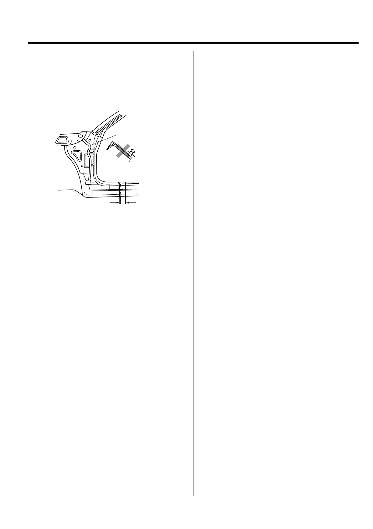
c) The tip of the spot welding machine should be
maintained to a minimum tolerance of 3 mm. Also
let area cool after 5 or 6 welds to minimize problems
caused by excessive heat.
3mm(0.2 in)
4 . Cutting and welding an removed area
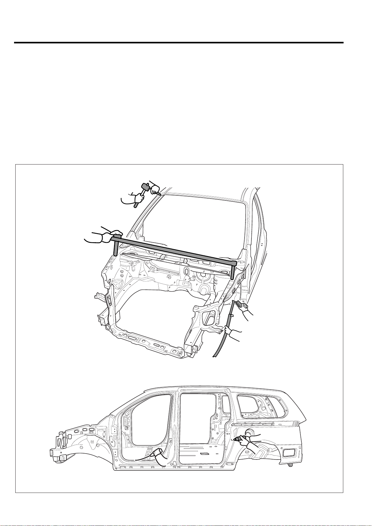
T o align a roof panel and a center pillar together f or butt
welding, temporarily fasten a steel flange to the roof
panel and then apply the new center pillar panel.
Remove the flange when final welding is done.
b) Finish areas that have been brazed by applying
body filler then smooth the area with a flexible file
and sander.
BVQBP6029
BVQBP6026
6. Applying anti-rust agent and body sealer
After coating the surface with anti-rust agent, apply
body sealer where necessary.
NOT
Apply body sealer before assembly.
5. Finishing after welding
a) Grind any areas that were plug welded or butt
welded using a disk grinder. Grind carefully to avoid
removing too much material. This degrades the
strength of the weld.
BVQBP6027
BVQBP6028
BVQBP6030
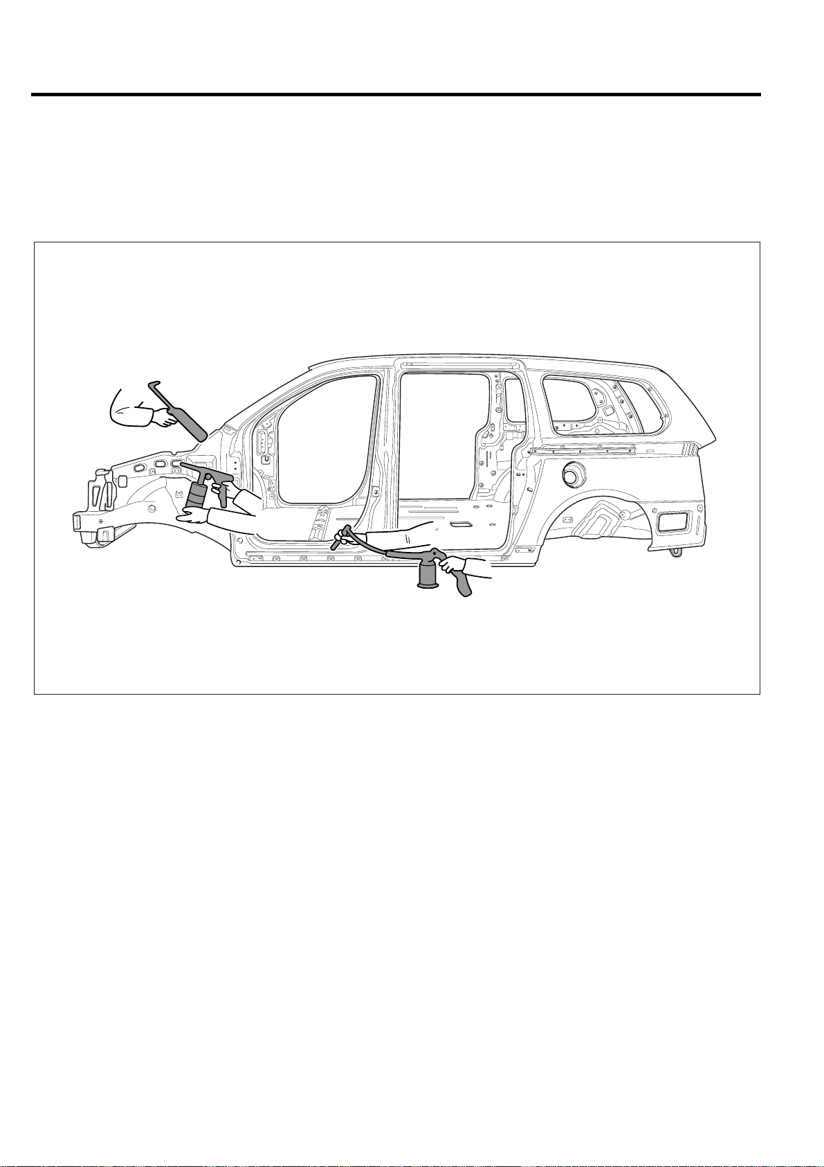
7. Anti-rust treatment
Apply anti-rust agent to inside of doors and sills by
spraying through access holes provided.
BVQBP6031
Page 55

BP-12 BODY PANEL REPAIR PROCEDURE
E
E
RADIATOR SUPPORT PANEL
ASSEMBLY
NOT
Before repairing, remove Engine and Suspension
Components.
Refer to the body dimension charts and measure the vehicle
to determine straightening and alignment requirements. The
body must be returned to its original dimension before you
begin the repair procedure.
REMOVAL
1. Drill out all the spotwelds to separate radiator support
panel from front side member(10 points) and fender
apron upper outer panel(10 points).
NOT
When spotwelded portions are not apparent, remove
paint with a rotary wire brush
BVQBP6033
BVQBP6032
BVQBP6034
BVQBP6035
Page 56

BODY PANEL REPAIR PROCEDURE BP-13
2 . Drill out all the spotwelds to separate radiator support
panel from front side member(7 points).
BVQBP6036
3. Using a belt sander, remov e the front side member by
drilling out the spotwelds(4points).
5. Before welding the radiator support panel, apply the
epoxy primer to the interior of the radiator support panel
BVQBP6039
4. Clean MIG welds with a disc grinder.
BVQBP6037
BVQBP6038
Page 57

BP-14 BODY PANEL REPAIR PROCEDURE
E
INSTALLATION
1. Drill 6mm holes in the new radiator support panel for
MIG plug welding.
2. Remove paint from both sides of all portions that are to
be welded such as peripheries of MIG plug weld holes.
BVQBP6040
3. T emporarily install new parts in place.
4. Measure each measurement point (Refer to the BODY
DIMENSIONS) and correct the installation position
6 . Clean MIG welds with a disc grinder.
NOT
• Be careful not to grind welded portions too much.
• The internal parts will be stronger if the weld traces
are not ground.
BVQBP6043
7. After welding the radiator support panel, apply the
epoxy primer and anti-corrosion to the radiator support
panel
5. MIG plug weld all holes.
BVQBP6041
BVQBP6042
BVQBP6044
Page 58

BODY PANEL REPAIR PROCEDURE BP-15
COWL SIDE OUTER PANEL
REMOVAL
1. Drill out all spotwelds to separate cowl side outer panel
from cowl assembly and fender apron inner panel(33
points).
BVQBP6045
2. Using a disc grinder, remove the co wl side outer panel
by drilling out the MIG lap welds.(5 points)
4. Before welding the cowl side outer panel, apply the
epoxy primer to the interior of the cowl side outer panel.
BVQBP6048
3. Clean MIG welds with a disc grinder.
BVQBP6046
BVQBP6047
Page 59

BP-16 BODY PANEL REPAIR PROCEDURE
E
INSTALLATION
1. Drill 6mm holes in the new cowl side outer panel for
MIG plug welding.
2. Remove paint from both sides of all portion that are to
be welded such as peripheries of MIG plug weld holes.
BVQBP6049
3. T emporarily install new parts in place.
4. MIG plug weld all holes.
5 . Clean MIG welds with a disc grinder .
NOT
Be careful not to grid welded portion too much.
The internal parts will be stronger if the weld traces are
not ground.
BVQBP6051
6. After welding the cowl side outer panel, apply the epoxy
primer and anti corrosion to the cowl side outer panel.
BVQBP6052
BVQBP6050
Page 60

BODY PANEL REPAIR PROCEDURE BP-17
FENDER APRON INNER LOWER PANEL
REMOVAL
1. Drill out all the spotwelds to separate fender apron inner
lower panel from fender apron inner upper panel, shock
absorber housing panel and front side member.
BVQBP6053
2 . Clean MIG welds with a disc grinder .
BVQBP6055
3. Before welding the fender apron inner lower panel, apply
the epoxy primer to the interior of the fender apron inner
lower panel.
BVQBP6054
BVQBP6056
Page 61

BP-18 BODY PANEL REPAIR PROCEDURE
E
INSTALLATION
1. Drill 6mm holes in the new fender apron inner lower
panel for MIG plug welding.
2. Remove paint from both sides of all portion that are to
be welded such as peripheries of MIG plug weld holes.
BVQBP6058
3. T emporarily install new parts in place.
5 . Clean MIG welds with a disc grinder .
NOT
Be careful not to grid welded portion too much.
The internal parts will be stronger if the weld traces are
not ground.
BVQBP6061
6. After welding the fender apron inner lower panel, apply
the epoxy primer and anti corrosion to the cowl side
outer panel
4. MIG plug weld all holes.
7. Prepare the exterior surfaces for priming using wax
and grease remover .
8. Apply metal conditioner and water rinse.
9. Apply conversion coating and water rinse.
10. Apply the two-part epoxy primer
BVQBP6059
BVQBP6062
BVQBP6060
Page 62

BODY PANEL REPAIR PROCEDURE BP-19
FENDER APRON INNER UPPER PANEL
REMOVAL
1. Measure and mark the vertical cut lines on fender outer
mounting hole edge.
LH
65 mm
BVQBP6063
RH
70 mm
3 . Prepare all surfaces to be welded.
4. Clean MIG with a disc sander.
BVQBP6066
5. Apply the epoxy primer to interior of the fender apron
inner upper panel.
BVQBP6064
2 . Cut through the fender apron inner upper panel cutline.
BVQBP6065
BVQBP6067
Page 63

BP-20 BODY PANEL REPAIR PROCEDURE
E
INSTALLATION
1. T emporarily Fit and clamp the fender inner upper panel
in place.
2. Measure each measurement point(refer to the BODY
DIMENSIONS) and correct the installation position.
BVQBP6068
3. MIG butt weld all seams.
5 . Clean MIG welds with a disc grinder.
NOT
Be careful not to grid welded portion too much.
The internal parts will be stronger if the weld traces are
not ground.
BVQBP6071
6. Apply the epoxy primer and anti-corrosion to the fender
apron inner upper panel.
BVQBP6069
4. After welding the fender apron inner upper panel,
measure each measurement point(refer to the BODY
DIMENSIONS) and correct the installation position.
7. Prepare the exterior surfaces for priming using wax
and grease remover .
8. Apply metal conditioner and water rinse.
9. Apply conversion coating and water rinse.
10. Apply the two-part epoxy primer.
BVQBP6072
BVQBP6070
Page 64

BODY PANEL REPAIR PROCEDURE BP-21
FRONT SIDE MEMBER
LH
RH
35 mm
260 mm
80 mm
MIG plug welding
MIG butt welding
50 mm
BVQBP6073
Page 65

BP-22 BODY PANEL REPAIR PROCEDURE
E
E
REMOVAL
NOT
This procedure is to be used only for repair of minor damage
to the front side member and when it is impossible to
straighten the damaged side member.
The following procedure illustrates a repair for the front left
side member.
The procedure may also be applied to the front left side
member.
1. Measure and mark the vertical cut lines on front side
member inner tooling hole outer side.
3 . Drill out all the spotwelds to separate fender apron inner
panel from front side member.
NOT
• When spotwelded portions are not apparent,
remove paint with a rotary wire brush.
• In order to perform cutting and separation of
spotwelded points use a spot weld cutter which is
larger than the size of the nugget to make a hole
only in the panels to be replaced.
BVQBP6074
2. Drill out the spotwelds to separate front side member
from engine mounting bracket.(6points)
BVQBP6075
BVQBP6076
BVQBP6077
Page 66

BODY PANEL REPAIR PROCEDURE BP-23
E
3. Cut through the front side member inner and outer at
cutlines.
NOT
Take care not to cut through front side member inner
reinforcement.
BVQBP6078
4. Prepare all surfaces to be welded
INSTALLATION
1. Transcribe the front side member inner and outer cut
line to the new front side member, cut to length and
chamfer butt end to improve weld surface.
2. Drill 8mm holes in new front side member for MIG plug
welding.
BVQBP6080
3. Fit and clamp the front side member inner and outer in
place.
BVQBP6079
4. MIG plug weld all holes and MIG butt weld all seams.
5. Measure each measurement point (Refer to the BODY
DIMENSIONS) and correct the installation position.
BVQBP6081
Page 67

BP-24 BODY PANEL REPAIR PROCEDURE
6 . Clean and prepare all welds, remove all residue.
7. MIG plug weld all holes.
BVQBP6082
8. Clean MIG welds with a disc grinder.
10. Apply the two-part epoxy primer to the interior of the
front side member.
BVQBP6085
11 . Apply an anti-corrosion agent as required
(Refer to the CORROSION PROTECTION).
12. Prepare the exterior surfaces for priming using wax
and grease remover .
13. Apply metal conditioner and water rinse.
BVQBP6083
9. MIG plug weld engine mounting bracket from front side
member.
14. Apply conversion coating and water rinse.
15. Apply the two-part epoxy primer.
16. Apply the correct seam sealer to all joints carefully
(Refer to the BOD Y SEALING LOCATIONS).
17. Reprime over the seam sealer to complete the repair.
BVQBP6084
Page 68

BODY PANEL REPAIR PROCEDURE BP-25
E
FRONT PILLAR
REMOVAL
1. Measure and mark the each cut line on the front outer
pillar at 130mm from the roof panel end line as indicated
in the illustration.
130mm
50mm
50mm
BVQBP6086
2. Measure and mark the cut line on front side sill outer
panel as shown in the illustration.
3. To remove the front pillar, grind away and drill out all
welds and cut all laser welds attaching the cowl side
upper outer panel as shown in the illustration.
NOT
If it is possible that the cowl side upper outer panel is
reusable, be careful not to damage it while removing.
BVQBP6088
4. Drill out all welds attaching the front pillar to cowl cross
member bracket.
100mm
5. Remove spotwelds attaching cowl cross member
bracket to remo ve side inner pillar .
BVQBP6087
BVQBP6089
Page 69

BP-26 BODY PANEL REPAIR PROCEDURE
E
6 . Before cutting front pillar, be sure to support roof panel.
BVQBP6090
7. Cut through the front pillar outer at cutline.
9. Before cutting the front side sill outer panel, make a
rough cut the side sill outer panel only .
NOT
When cutting the front side sill outer panel, be careful
not to cut side outer reinforcement.
BVQBP6093
10. Drill out all the spotwelds to separate side outer panel
from side inner panel (82points).
BVQBP6091
8. Cut the front pillar through each cut line, taking care
not to damage the other panel as illustration.
Roof side outer
reinforcement
Front pillar
outer panel
Front pillar outer lower
Side inner panel
reinforcement
BVQBP6092
BVQBP6094
11. Cut the side outer reinforcement as shown in the
illustration.
BVQBP6095
Page 70

BODY PANEL REPAIR PROCEDURE BP-27
E
12. Cut the side sill inner panel ver tical cutting line and
remove the front pillar .
BVQBP6093
13. Straighten all flanges as necessary , prepare all surfaces
to be welded.
15. Apply the two-part epo xy primer to the interior of the
front side member
BVQBP6099
14. Clean all welds with a disc grinder.
NOT
• Be careful not to grind welded portions too much.
• The internal parts will be stronger if the weld traces
are not ground.
BVQBP6097
BVQBP6098
Page 71

BP-28 BODY PANEL REPAIR PROCEDURE
INSTALLATION
1. Transcribe the cut line to the new side inner panel, cut
to length and chamfer butt end to improve weld surface.
BVQBP6100
2. Transcribe the cut line to the new side outer
reinforcement and new front pillar , adding 30mm overlap
to end and cut to length.
3. Drill 8mm holes along outer panel flanges in production
location for attachment to other panels.
4. Transcribe the cutline to the ne w side inner panel, adding
30mm overlap to end and cut to length.
5. Drill 8mm holes in the side inner panel for MIG plug
welding.
6. Fit and clamp the new side inner panel in place for
welding.
7. MIG plug weld all holes and MIG butt weld the seams.
BVQBP6102
8. T emporarily install front pillar outer panel in place.
BVQBP6101
9. Measure and each measurement point (Refer to the
BODY DIMENSIONS) and correct the installation
position.
10. If necessary , make temporary welds, and then chec k
to confirm that the closing and fit for windshield glass,
door and fender are correct.
BVQBP6103
Page 72

BODY PANEL REPAIR PROCEDURE BP-29
E
11 . MIG butt weld front pillar outer panel and side sill outer
reinforcement seams.
12. Reattach the cut away front pillar outer panel section,
then MIG butt weld.
Front pillar outer
panel section
100mm
BVQBP6104
13. MIG plug weld all holes and MIG butt weld all seams in
the side outer panel.
14. Clean and prepare all welds, remove all residue.
15. Apply body filler to joints and sand as needed.
17 . Clean all welds with a disc grinder.
NOT
• Be careful not to grind welded portions too much.
• The internal parts will be stronger if the weld traces
are not ground.
BVQBP6106
18. Before welding the cowl side upper outer panel, apply
the two-part epoxy primer and anti-corrosion agent to
the interior of the cowl side upper outer panel.
16. Apply the two-part epoxy primer to the interior of the
front pillar.
BVQBP6105
BVQBP6107
Page 73

BP-30 BODY PANEL REPAIR PROCEDURE
19. Install the cowl side upper outer panel in place.
20. MIG plug weld all holes.
21. Clean and prepare all welds, remove all residue.
BVQBP6108
22. Apply an anti-corrosion agent to the welded parts and
inside of front pillar (Refer to the CORROSION
PROTECTION).
27. Apply the correct seam sealer to all joints carefully
(Refer to the BOD Y SEALING LOCATIONS).
28. Reprime over the seam sealer to complete the repair.
BVQBP6110
23. Prepare exterior surfaces for priming, using wax and
grease remover .
24. Apply metal conditioner and water rinse.
25. Apply conversion coating and water rinse.
26. Apply the two-part epoxy primer.
BVQBP6109
Page 74

BODY PANEL REPAIR PROCEDURE BP-31
E
CENTER PILLAR
REMOVAL
1. Measure and mark the horizontal cutting line on center
pillar outer panel as indicated in the illustration.
150mm
50mm
50mm
BVQBP6111
2. Measure and mark the vertical cutline on side sill outer
panel 80mm from the front door step trim mounting
hole.
4 . Drill out all spotwelds and cut all laser welds attaching
the center outer pillar to the body to remove center
outer pillar.
BVQBP6114
5. Cut through center outer pillar and side sill outer panel
at cutlines.
NOT
When cutting side sill outer panel take care not to cut
through mating flanges or side outer reinforcement.
100mm
80mm
BVQBP6112
3. Before cutting center pillar , be sure to support roof panel.
BVQBP6113
BVQBP6115
6. After cutting side outer panel (center pillar outer & side
sill), cut the center pillar outer reinforcement and center
pillar inner panel.
BVQBP6116
Page 75

BP-32 BODY PANEL REPAIR PROCEDURE
E
7 . Remov e the center pillar.
NOT
When cutting center inner pillar, be careful not to cut
front seat belt mounting upper bracket.
Center pillar
Side outer
reinforcement
8. Determine if the side outer reinforcement is damaged
and needs to be replaced. If replacing is necessary,
mark out the damaged portion of the reinforcement.
Cut at cutlines and remove damaged portion.
outer panel
Side inner panel
BVQBP6117
9. Straighten all flanges as necessary .
10. Prepare all surfaces to be welded.
BVQBP6118
Page 76

BODY PANEL REPAIR PROCEDURE BP-33
INSTALLATION
1. In order to install center inner pillar drill out all spotwelds
attaching the roof side outer rail to center inner pillar to
separate them.
BVQBP6119
2. Transcribe the center outer pillar cutlines to the new
center outer pillar, adding 50mm o verlap at center lower
pillar ends.
3. Cut and chamfer butt end to improve weld surface.
6 . Clean MIG welds with a disc grinder.
BVQBP6122
7. Apply the epoxy primer to the side inner reinforcement.
4. Drill 6mm holes in overlap area and along outer panel
flanges.
BVQBP6120
5. MIG butt weld all seams in center inner pillar and sill
side outer reinforcement as shown in the illustration.
BVQBP6123
8. T emporarily install new center outer panel in place .
9. Screw center pillar in place.
10. Measure and each measurement point (Refer to the
BODY DIMENSIONS) and correct the installation
position.
BVQBP6121
BVQBP6113
Page 77

BP-34 BODY PANEL REPAIR PROCEDURE
11. Check the fit of the front and rear doors.
12. Reinstall center outer pillar and screw in place.
13. MIG plug weld all holes and MIG butt weld all seams.
14. Clean and prepare all welds, and remove all residue.
15. Apply body filler to the outer center pillar seam. Sand
and finish.
BVQBP6125
16. Apply the two-part epoxy primer to the interior of the
center pillar.
17. Apply an anti-corrosion agent to the welded parts and
interior of the center pillar (Refer to the CORROSION
PROTECTION).
18. Prepare exterior surfaces for priming, using wax and
grease remover .
19. Apply metal conditioner and water rinse.
20. Apply conversion coating and water rinse.
21. Apply the two-part epoxy primer.
22. Apply the correct seam sealer to all joints carefully
(Refer to the BOD Y SEALING LOCATIONS).
23. Reprime over the seam sealer to complete the repair.
BVQBP6126
BVQBP6127
BVQBP6128
Page 78

BODY PANEL REPAIR PROCEDURE BP-35
QUARTER PANEL
REMOVAL
1. Depending on the extent of damage, measure and mark
cutlines on the quarter outer panel as indicated in the
illustration
BA
170mm
A
70mm
B
2. Drill out all attaching spdtwelds the quarter outer
panel .
C
C
110mm
BVQBP6129
BVQBP6130
Page 79

BP-36 BODY PANEL REPAIR PROCEDURE
E
3 . Cut the quarter outer panel at cutlines and remove the
quarter outer panel as illustration.
NOT
When cutting the quarter outer panel, be careful not to
cut side inner panel.
4. Prepare all surfaces to be welded.
5 . Clean MIG welds with a disc grinder.
BVQBP6132
6. Apply the two-part epoxy primer to the quarter inner
panel.
BVQBP6131
BVQBP6133
Page 80

BODY PANEL REPAIR PROCEDURE BP-37
INSTALLATION
1. Transcribe the cutline to the new quarter outer panel,
adding 30mm for overlap at the old joint.
2. Drill 6 mm holes in overlap areas and along upper and
lower flanges of the new quarter outer panel for MIG
plug welding.
BVQBP6134
3. Fit and clamp the quarter outer panel in place.
6 . Apply body filler to the welded seam. Sand and finish.
Apply the two-part epoxy primer to the interior of the
quarter outer panel.
BVQBP6132
7. Apply an anti-corrosion agent to the welded parts and
interior of the quarter outer panel (Refer to the
CORROSION PROTECTION).
8. Prepare exterior surfaces for priming, using wax and
grease remover .
4. MIG plug weld all holes and MIG butt weld seams. At
the wheel well the edge must be crimped over the wheel
housing.
This joint may be welded after crimping or applying a
bead of adhesive which may be applied to the joint
before or after crimping.
5. Clean and prepare all welds, remove all residue.
BVQBP6135
9. Apply metal conditioner and water rinse.
10. Apply conversion coating and water rinse.
11 . Apply the two-part epoxy primer.
BVQBP6133
Page 81

BP-38 BODY PANEL REPAIR PROCEDURE
E
E
REAR FLOOR SIDE MEMBER
REMOVAL
NOT
Because the rear floor side members are designed to absorb
energy during a rear collision, care must be used when
deciding to use this repair method. This repair is
recommended only for moderate damage to the vehicle,
where distortions do not extend forward of the trunk region.
If the damage is more severe, then the entire side member
assembly should be replaced at the factory seams without
employing this sectioning procedure.
The following procedure applies when only one rear floor
side member needs to be replaced. If both side members
are damaged and need to be replaced, then the procedure
of rear floor side members and rear floor section should be
followed.
Refer to the body dimension charts and measure the vehicle
to determine straightening and alignment requirements.
The body must be returned to its original dimensions before
beginning the repair procedure.
1. Depending on the extent of damage, if the right side
member is to be replaced it should be measured and
marked 15mm from the rear floor side member end.
2. Cut through rear floor side member at cutline being
careful not to cut rear floor side member reinforcement.
BVQBP6139
3. Remove the rear floor side member by drilling out all
attaching spotwelds.
15 mm
BVQBP6138
NOT
The flowing procedure illustrates a repair for the right
rear floor side member. The procedure may also be
applied the left rear floor side member.
BVQBP6140
4. Using a belt sander, remove the rear floor side member
by drilling out the spotwelds.
5. Prepare all surfaces to be welded.
BVQBP6141
Page 82

BODY PANEL REPAIR PROCEDURE BP-39
6 . Clean MIG welds with a disc grinder .
BVQBP6142
7. Apply the two-part epoxy primer to the rear floor side
member.
BVQBP6143
Page 83

BP-40 BODY PANEL REPAIR PROCEDURE
INSTALLATION
1. T ranscribe the cutline to the new rear floor side member.
Cut at line and drill out the spotwelds attaching the
reinforcement and separate it.
BVQBP6144
2. Fit and clamp the new rear floor side member in place
for welding.
Measure to ensure dimensions are accurate as given
in the body dimension charts.
4. Clean and prepare all surfaces to be welded and remove
all residue.
BVQBP6147
5. Apply the two-part epoxy primer to the interior of the
rear floor side member.
6. Prepare exterior surfaces for priming, using wax and
grease remover .
7. Apply metal conditioner and water rinse.
BVQBP6145
3. MIG plug weld at the holes and MIG butt weld the seam
in the side member.
8. Apply conversion coating and water rinse.
9. Apply the two-part epoxy primer.
BVQBP6148
BVQBP6146
Page 84

BODY PANEL REPAIR PROCEDURE BP-41
10. Apply the correct seam sealer to all joints.
11. Reprime over the seam sealer to complete the repair.
BVQBP6149
12. After completing body repairs, carefully apply
undercoating to the underbody .
13. In order to improve corrosion resistance, if necessary ,
apply on underbody anti-corrosion agent to the panel
which is repaired or replaced.
BVQBP6150
Page 85

BP-42 BODY PANEL REPAIR PROCEDURE
E
REAR COMBINA TION LAMP HOUSING P ANEL
REMOVAL
1. Drill out all spotwelds to separate rear combination lamp
housing panel from side inner panel, quarter panel and
back panel
NOT
When spotwelded portions are not apparent, remove
paint with a rotary wire brush.
3. Apply the two-part epoxy primer to the interior of the
rear floor side member.
BVQBP6153
2. Clean MIG welds with s disc grinder.
BVQBP6151
BVQBP6152
Page 86

BODY PANEL REPAIR PROCEDURE BP-43
INSTALLATION
1. Drill 6mm holes in the new rear combination lamp
housing panel for MIG plug welding.
BVQBP6154
2. Fit and clamp the new rear combination lamp housing
panel in place for welding.
Measure to ensure dimensions are accurate as given
in the body dimension charts.
4. Clean and prepare all surfaces to be welded and remove
all residue.
BVQBP6157
5. Apply the two-part epoxy primer to the interior of the
rear floor side member.
6. Prepare the exterior surfoces for priming using wax
and grease remover .
7. Apply metal conditioner and water rinse.
3. MIG plug weld all holes
8. Apply conversion coating and water rinse.
9. Apply the two-part epoxy primer.
BVQBP6155
BVQBP6158
BVQBP6156
Page 87

BP-44 BODY PANEL REPAIR PROCEDURE
E
BACK PANEL
REMOVAL
1. Drill out all spotwelds to separate back panel from side
inner panel, quarter panel and back panel.
NOT
When spotwelded portions are not apparent, remove
paint with a rotary wire brush.
BVQBP6159
3. Apply the two-part epoxy primer to the interior of the
rear floor side member.
BVQBP6161
2. Clean MIG welds with s disc grinder.
BVQBP6160
Page 88

BODY PANEL REPAIR PROCEDURE BP-45
INSTALLATION
1. Drill 6mm holes in the new Back panel for MIG plug
welding.
BVQBP6162
2. Fit and clamp the new back panel in place for welding.
Measure to ensure dimensions are accurate as given
in the body dimension charts.
4. Clean and prepare all surfaces to be welded and remove
all residue.
BVQBP6165
5. Apply the two-part epoxy primer to the interior of the
rear floor side member.
6. Prepare the exterior surfaces for priming using wax
and grease remover .
7. Apply metal conditioner and water rinse.
3. MIG plug weld all holes.
8. Apply conversion coating and water rinse.
9. Apply the two-port epoxy primer.
BVQBP6163
BVQBP6166
BVQBP6164
Page 89

Body Sealing
Locations
FLOOR
FRONT AND SIDE BODY ...........................BS - 4
DOOR ..............................................................BS - 7
HOOD ..............................................................BS - 10
TAIL GATE ........................................................BS - 11
..............................................................BS - 2
BS
Page 90

BS-2 BODY SEALING LOCATIONS
FLOOR
B
C
A
D
E
G
<T op View>
BVQBS6100
F
<Bottom View>
A B
BVQBS6102
BVQBS6101
BVQBS6103
Page 91

BODY SEALING LOCATIONS BS-3
C D
BVQBS6105BVQBS6104
E F
G
BVQBS6107BVQBS6106
BVQBS6108
Page 92

BS-4 BODY SEALING LOCATIONS
FRONT AND SIDE BODY
C
G
S
D
A
K
M N O
BVQBS6200
H
Q
E,F
R
B
A B
BVQBS6202
P
BVQBS6201
BVQBS6203
Page 93

BODY SEALING LOCATIONS BS-5
C D
BVQBS6205BVQBS6204
E F
G H
BVQBS6208
K M
BVQBS6207BVQBS6206
BVQBS6209
BVQBS6210
BVQBS6211
Page 94

BS-6 BODY SEALING LOCATIONS
N O
BVQBS6213BVQBS6212
P Q
R S
BVQBS6215BVQBS6214
BVQBS6217BVQBS6216
Page 95

BODY SEALING LOCATIONS BS-7
DOOR
< Views >
B
A
C
D
A B
BVQBS6301
C D
BVQBS6300
BVQBS6302
BVQBS6303
BVQBS6304
Page 96

BS-8 BODY SEALING LOCATIONS
< Section >
G
B
F
B'
D
A
A'
E
C
C'
A B
a
B'
G'
D'
E'
H
H'
BVQBS6305
C
a
Door outer panel
Door inner panel
Door inner
A - A'
panel
Door outer
panel
b
C - C'
B - B'
BVQBS6307BVQBS6306
b
5mm
1.5 mm
2.5 mm
BVQBS6308
Page 97

BODY SEALING LOCATIONS BS-9
D E
e
d
2.5 mm
5mm
1.5 mm
e
d
G
d'
d'
D - D'
E - E'
BVQBS6310
F
F - F'
f
BVQBS6311BVQBS6309
f
g
g
5mm
1.5 mm
H
2.5 mm
G - G'
h
5mm
1.5 mm
2.5 mm
h
H - H'
BVQBS6312
BVQBS6313
Page 98

BS-10 BODY SEALING LOCATIONS
HOOD
< Section >
A
A
B
B'
A'
C
C'
BVQBS6400
a
B
1.5 mm
5 mm
B - B'
a
BVQBS6402
A - A'
C
BVQBS6401
b
5 m
1.5 mm
m
C - C'
b
BVQBS6403
Page 99

BODY SEALING LOCATIONS BS-11
TAIL GATE
< Section >
A
A'
C
C'
B
B'
A
a'
a'
5 mm
m
1.5 m
B
C
5 mm
1.5 mm
B - B'
BVQBS6500
BVQBS6502
A - A' C - C'
BVQBS64501
BVQBS6503
Page 100

Corrosion
protection
ZINC-GALVANIZED STEEL PANELS
ZINC-PHOSPHATE COAT & CATIONIC
ELECTRODEPOSITION PRIMER
ANTI-CORROSION PRIMER ....................CP - 5
ANTIVIBRATION PADS-LOCATION
& SECTION
ATTACHMENT OF ANTIVIBRATION
PADS
UNDER BODY COAT
FLOOR .............................................................CP - 8
SIDE BODY ......................................................CP - 9
CAVITY WAX INJECTION...........................CP - 10
UNDER BODY ANTI-CORROSION
AGENT
......................................................CP - 6
..............................................................CP - 7
..............................................................CP - 13
....CP - 2
...........CP - 4
CP
 Loading...