

Page 1
2D Code Reader
Danger
Warning
Caution
Note
Reference
Caution
Warning
SR-500 Series
Instruction Manual
96M11012
Use of controls or adjustments or performance of procedures
other than those specified herein may result in hazardous
radiation exposure.
Item SR-500/510
Wavelength 655nm
Output 90μW
Pulse width 200μs
Laser Class
* The laser classification for FDA(CDRH) is implemented based on IEC60825-1 in
accordance with the requirements of Laser Notice No.50.
• Follow the instructions mentioned in this manual.
Otherwise, injury to the human body (eyes and skin) may
result.
Precautions on class 1 laser products
• Do not disassemble this product. Laser emission from
this product is not automatically stopped when it is
disassembled.
• Do not stare into the beam.
Class 1 Laser Product
(IEC60825-1, FDA(CDRH) Part1040.10*)
Failure to follow instructions may lead to death or serious
injury.
Failure to follow instructions may lead to injury.
Failure to follow instructions may lead to product damage or
malfunctions.
Provides additional information on proper operations that can
be easily mistaken.
Provides advanced and useful information for operation.
Safety Information for SR-500 Series
General cautions
• Take substantial safety measures to avoid any damage in the unlikely event
of a problem occurring.
• Do not modify the SR-500 Series, or use it in any way other than described
in the specifications.
• When the SR-500 Series is used in combination with other devices, functions and performance may be degraded, depending on the operating
conditions and surrounding environment.
• Parts of this manual may not be used or duplicated without express permission.
• The contents of his manual are subject to change without notice.
Operating Precautions
•
Do not use a voltage other than 5VDC with the SR-500
Series. Doing so may lead to damage on the unit.
When using the dedicated communication units (NX-50
Series, N-R2/R4/UB/L1, or DV-90 Series), use a power
supply within the appropriate range for each unit.
• Be sure to turn the power off to devices attached to the
SR-500 Series when you plug or unplug the cables. Failure
to do so may cause damage to the SR-500 Series.
• Do not disassemble or modify the SR-500 Series. Doing so
may lead to damage on the unit.
• Keep the cables away from high-tension cables or power
sources. Otherwise, noise could cause malfunctions or
accidents.
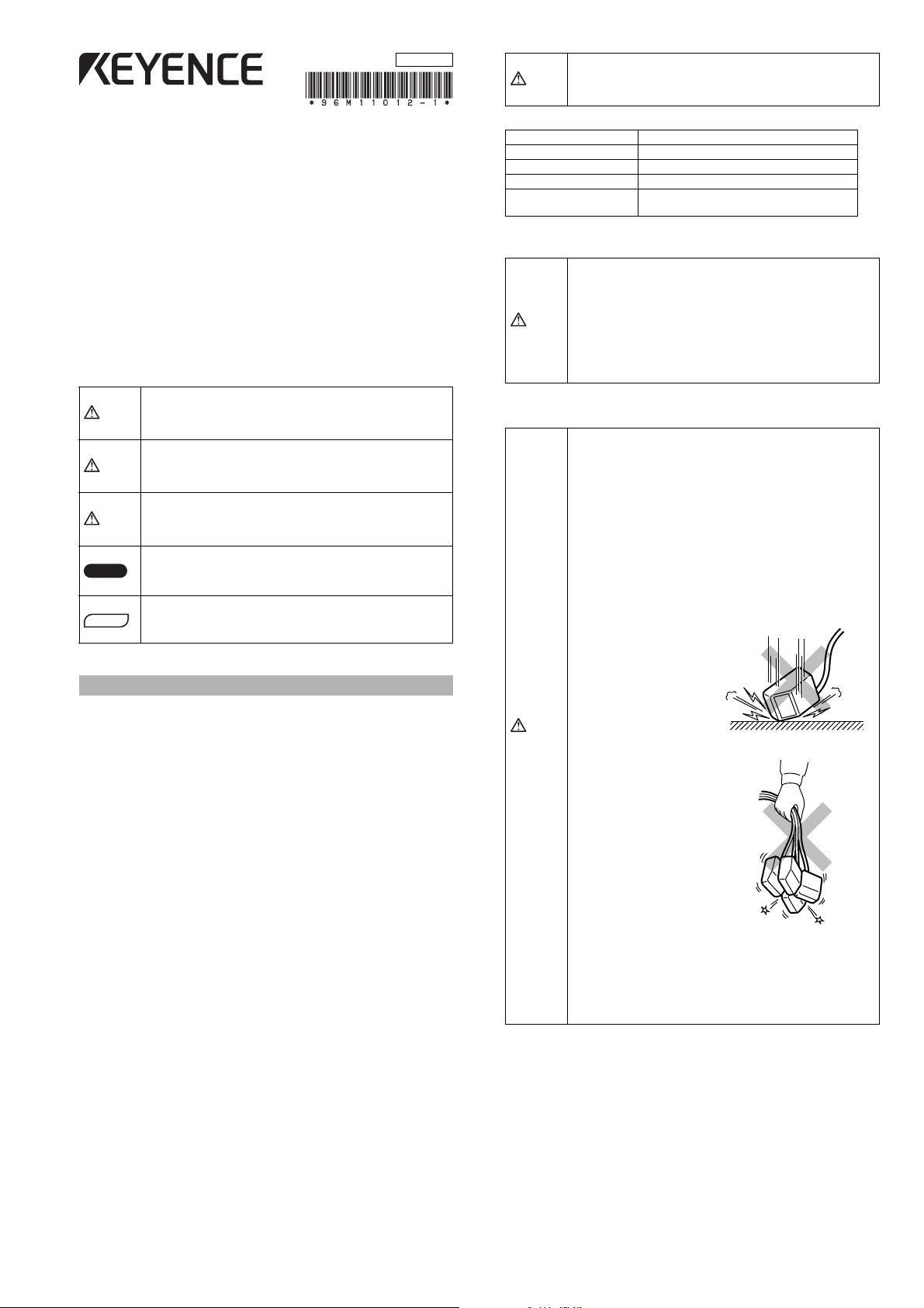
• The SR-500 Series is a
precision instrument. Do
not apply shock to the
instrument or drop it. Be
especially careful when
transporting or installin g the
unit.
Caution
• Do not hold the SR-500
Series by its cable. The
units may become
damaged if they strike
each other.
Important notes
When planning to use the SR-500 Series in situations or environments
described below, use it with ample margins in terms of ratings and functions,
and take appropriate failsafes and other safety measures.
• Usage in situations or environments other than those described in this
manual.
• Usage with nuclear power controls, railroad installations, aircraft installations, automotive equipment, combustion equipment, medical equipment,
recreational equipment, or safety devices.
• Applications that are determined to have a large influence on life or property, and additional safety measures are desired.
Safety precautions on laser product
The 2D Code Reader SR-500 Series uses a visible semiconductor laser as a
target pointer for adjusting the reading position.
This laser has a wavelength of 655nm and is classified as a Class 1 laser
under IEC standards (IEC60825-1: "Safety of Laser Products").
• Do not allow water, oil, dust, or other foreign substances to
stick to the scanner. This may cause read errors. Use a
soft, dry cloth to wipe any substances from the scanner.
(Do not use a cloth dipped in alcohol or other cleaning
substance.)
1
E SR-500-IM
Page 2
Foreign Safety Precautions
Danger
Warning
Caution
Note
Reference
Caution
Warning
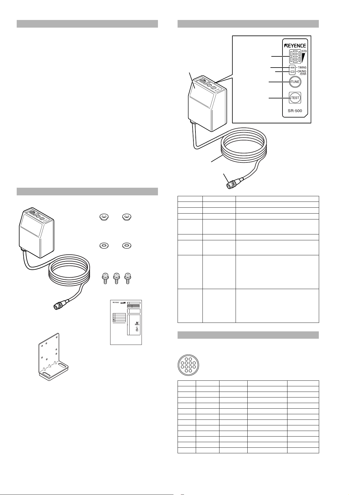
Main unit
Instruction Manual
Mounting bracket ..... 1
Insulating spacer ......2
Washer .....................2
Installation
screw (M3)................3
Multiple LED
indicator
Timing LED
TUNE switch
TEST switch
Window
Cable
Connector
OK/NG/ERR LED
Head cable as seen from the connector
RP17-13PA-12PC plug (male)
Made by Hirose Electric Co., Ltd.
Precautions on UL certificate
The SR-500 Series complies with the following UL and CSA standards. The
equipment has received UL and C-UL certificate.
• Approved standard: UL508 (Listed), UL60950-1 (R/C)
• UL File No: E207185, E167973
• UL category: NRAQ/NRAQ7, NWGQ2/NWGQ8
• SR-500 Series must use a Class 2 power source according to NEPA70
(NEC: National Electrical Code).
• Pollution degree: 2
• Overvoltage category: I
Precautions on CE marking
The SR-500 Series meets the requirements for the EMC Directive when used
with the following conditions and the CE marking is applied.
• Applicable standard (EMI): EN55011, Class A
• Applicable standard (EMS): EN61000-6-2
* Use communication cables and power cables no longer than 30m.
Precautions on FCC
The SR-500 Series complies with the following FCC regulation.
• FCC Part 15, SubPart B, Class A, Digital devices
EN55022, Class B
EN61000-6-1
Part Names and Functions
Precautions on
Canada IC (Industry Canada) regulations
The SR-500 Series complies with the following IC regulation.
• ICES-003, Class A, Digital devices
Checking the Package Contents
2D Code Reader
SR-500 Series
Instruction Manual
Failure to follow instructions may lead to death or serious
injury.
Failure to follow instructions may lead to injury.
Failure to follow instructions may lead to product damage or
malfunctions.
Provides additional information on proper operations that can
be easily mistaken.
Provides advanced and useful information for operation.
Safety Information for SR-500 Series
General cautions
•Take substantial safety measures to avoid any damage in the unlikely event
of a problem occurring.
•Do not modify the SR-500 Series, or use it in any way other than described
in the specifications.
•When the SR-500 Series is used in combination with other devices, functions and performance may be degraded, depending on the operating
conditions and surrounding environment.
•Parts of this manual may not be used or duplicated without express permission.
•The contents of his manual are subject to change without notice.
Important notes
When planning to use the SR-500 Series in situations or environments
described below, use it with ample margins in terms of ratings and functions,
and take appropriate failsafes and other safety measures.
•Usage in situations or environments other than those described in this
manual.
•Usage with nucle ar power controls, railroad installations, aircraft installations, automotive equipment, combustion equipment, medical equipment,
recreational equipment, or safety devices.
•Applications that are determined to have a large influence on life or property, and additional safety measures are desired.
Safety precautions on laser product
The 2D Code Reader SR-500 Series uses a visible semiconductor laser as a
target pointer for adjusting the reading position.
This laser has a wavelength of 655nm and is classified as a Class 1 laser
under IEC standards (IEC60825-1: "Safety of Laser Products").
96M11012
*The laser classification for FDA(CDRH) is i mplemented bas ed on IEC 60825-1 in
Operating Precautions
1
Use of controls or adjustments or performance of procedures
other than those specified herein may result in hazardous
radiation exposure.
Item SR-500/510
Wavelength 655nm
Output90μW
Pulse width 200μs
Laser Class
accordance with the requirements of Laser Notice No.50.
•Follow the instructions mentioned in this manual.
Otherwise, injury to the human body (eyes and skin) may
result.
Precautions on class 1 laser products
•Do not disassemble this product. Laser emission from
this product is not automatically stopped when it is
disassembled.
•Do not stare into the beam.
•
Do not use a voltage other than 5VDC with the SR-500
Series. Doing so may lead to damage on the unit.
When using the dedicated communication units (NX-50
Series, N-R2/R4/UB/L1, or DV-90 Series), use a power
supply within the appropriate range for each unit.
•Be sure to turn the power off to devices attached to the
SR-500 Series when you plug or unplug the cables. Failure
to do so may cause damage to the SR-500 Series.
•Do not disassemble or modify the SR-500 Series. Doing so
may lead to damage on the unit.
•Keep the cables away from high-tension cables or power
sources. Otherwise, noise could cause malfunctions or
accidents.
•The SR-500 Series is a
precision instrument. Do
not apply shock to the
instrument or drop it. Be
especially careful when
transporting or installing the
unit.
Caution
•Do not hold the SR-500
Series by its cable. The
units may become
damaged if they strike
each other.
•Do not allow water, oil, dust, or other foreign substances to
stick to the scanner. This may cause read errors. Use a
soft, dry cloth to wipe any substances from the scanner.
(Do not use a cloth dipped in alcohol or other cleaning
substance.)
(IEC60825-1, FDA(CDRH) Part1040.10*)
Number Name Function
Window Reads 2D codes and barcodes.
Cable Cable is 1.8m long.
Connector Connects to the communication unit.
Multiple LED
indicator
Displays the operation statuses, including the
parameter number during decoding, reading
stability, and operation mode.
Timing LED Lights when the timing input is on.
OK/NG/ERR
LED
TUNE switch
• Lights green when the output is OK.
• Lights orange when the output is NG.
• Lights red when the output is ERR.
Use this switch to perform the following operations:
• Light read position adjustment laser pointer
• Display registered parameter banks
(Up to 8 banks can be registered)
• Start parameter teaching
• Read all of the program codes
• Reset error
Use this switch to perform the following operations:
•Start test mode
• Press for a short period of time (under 1 second)
Class 1 Laser Product
TEST switch
to read a code only once.
• Fix the communication settings as the default
value when sending or receiving settings.
(Press and hold for 6 seconds.)
Connection and Wiring Method
E SR-500-IM
SR-500 Series connector pin position
E SR-500-IM
21
610594
3
8
7
1211
Pin No. Wire color Symbol name Description Signal direction
1 White OK OK output Output
2 Gray NG NG output Output
3 Purple TxD RS-232C send Output
4 Blue CTS RS-232C send OK Input
5 Lt. blue BUSY BUSY output Output
6 Green PRESET Preset input Input
7 Brown RxD RS-232C receive Input
8Pink RTS
RS-232C send request
9 Orange ERROR ERROR output Output
10 Yellow TIMING Timing input Input
11 Red +5V +5V power supply –
12 Black GND (SG) Common GND –
* The shielded wire is directly connected to the common GND.
2
Output
Page 3

Connecting the power
Note
GND
+5V
12
+
11
5VDC
10kΩ
100Ω
TIM
GND
12
6,10
With or without
contacts
4.7kΩ
5VDC
Internal circuit
Internal circuit
GND
OK/NG
12
+
1, 2,
5, 9
Load
* Rated load: 24VDC (30mA) or less
3.3kW
6.8kW
33V
The optimum angle for the
SR-500 Series is 20° from
the line perpendicular to
the back of the unit.
Reading distance
20°
Connect using a cable that is
4.8m or less in length.
• Do not use a reverse connection to the power supply.
Doing so may lead to damage on the unit.
• Use a stable power supply that is 5VDC+5%, -10%. Using
a power supply that exceeds this range may lead to
damage on the unit.
• Use an NEC Class 2 output power supply when operating
under UL standards.
Timing and preset input wiring
The timing input is used on the SR-500 Series to start reading 2D codes or barcodes.
The preset input is used on the SR-500 Series to register data from the 2D
codes or barcodes.
• The timing and preset inputs are both non-voltage inputs.
Installing the SR-500 Series
Adjust to the following installation angle and distance when installing the SR500 Series.
Adjusting the installation angle
The scanner for the SR-500 Series should be tilted 20° compared to the 2D
code or barcode surface to read. Installing at this angle provides the optimal
reading stability.
Adjusting the installation distance
1 Press the [TUNE] switch on the SR-500 Series to emit the laser pointer, and
adjust the installation distance.
The laser pointer emits as shown in the diagrams below.
For the SR-500
The point where the laser pointers intersect
is the optimum reading distance.
Adjust the laser pointer intersection so that
it lies directly in the middle of the 2D code
and barcode.
29mm
OK/NG/ERROR/BUSY output wiring
• OK output is used when the reading is successful, checked against the preset data, and determined to be okay.
• NG output is used when the reading is checked against the preset data
and determined to be NG (not good).
• ERROR output is used when the reading has failed.
• BUSY output is used as the waiting signal when a timing input has not been
received by the SR-500 Series, or it is used as the preset data registration
completion signal or the control signal for the external light.
Each signal is output in the format of NPN open collector.
RS-232C wiring
Use the following wiring to connect to a computer.
SR-500 Series DOS/V computer
3
TxD
4
CTS
7
RxD
8
RTS
12
+5V
11
Round
connector
12-pin
(male)
+
D-sub 9-pin
(female)
#4-40 screw
2
7
3
8
5
4
6
RxD(RD)
RTS(RS)
TxD(SD)
CTS(CS)
GND(SG)GND
DTR(ER)
DSR(DR)
Laser pointer
For the SR-510
The two laser pointers indicate
the laser pointer width.
Adjust the laser pointers so
that the 2D code and barcode
lie directly in the middle.
Laser pointer
2 Use the [TEST] switch and check the reading stability in both reading rate
measurement mode (press for 1 second) and reading position measurement
mode (press for 3 seconds). Fine tune the reading distance and angle for the 2D
codes and barcodes that you plan to use.
When using workpieces such as directing marking on boards
Reference
3
where there is low contrast between the code and the
background, increase the installation angle (larger than 20°)
to stabilize the reading.
100mm
E SR-500-IM
Page 4

Note
• Do not set the scanner at an angle where it is nearly
20°
Range of
±15° is not
usable
Included installation
screw M3x3
Mounting bracket
Note
Installation screw (M3)
parallel with the 2D codes or barcodes. The reading
becomes unstable due to reflected light and misreading
may occur.
• The distances or angles that can be used for reading may
vary with the size or print quality of the 2D code or barcode
being read.
Use test mode to actually read the 2D code or barcode
during installation.
Mounting SR-500 Series
There are two methods for installation: using the mounting bracket, and not
using the mounting bracket.
Installing with the mounting bracket
2 Secure the mounting bracket in place.
• Purchase installation screws (M4) separately. (Use
Note
screws that are 10mm or longer.)
• Be sure to use the insulating spacers on the side
closest to the mounting brackets to suppress noise.
Installation screw (M4)
Washer
Insulating spacer
1 The SR-500 Series can be mounted with the supplied mounting bracket.
The SR-500 Series can be installed in the directions shown in the diagrams
below. Choose a mounting direction that best fits your application.
Vertical (One direction)
Horizontal (Two directions)
Mounting bracket
Installing without the mounting bracket
Mount the SR-500 Series so that the scanner is tilted 20° from the 2D code or
barcode. For more information about the installation angle and distance, see
"Installing the SR-500 Series".
1
Secure the mounting position of the SR-500 series with three screws (M3).
The SR-500 Series can be installed in the directions shown in the diagrams
below. Choose a mounting direction that best fits your application.
Purchase installation screws separately. The type of
screw required depends on factors such as the thickness
of the board where the SR-500 Series is mounted.
The effective depth of screws for the SR-500 Series is
4mm.
Vertical (One direction)
Installation screw (M3)
Included installation
screw M3x3
The SR-500 Series can also be mounted with the cable pulled in either direction
horizontally.
E SR-500-IM
Horizontal (Two directions)
The SR-500 Series can also be mounted with the cable pulled in either direction
horizontally.
Note
Be sure to insulate the area between the mounting
surface to suppress noise.
4
Page 5

Dimensions
66.5
SR-500 Series
(41.5)
5.5
3-M3
Depth 5mm
25
(40)
15
SR-500 Series (with mounting bracket)
6
35
47
4.1
φ
2-
84.1
69.6
25
Mounting bracket
96
25
5.5
5.5
25
36
36
39.5
47
15(Screw position)
9(Screw position)
23.6
3.1
6
4-(R2.9)
2-5.8
25
7-φ3.4
19.6
3
* Use a screw position within this range
13.6
20°
46.4
35
2-R2
47
36
2-R2
60
70.5
6
2.0
18.7
90°
27.1
Specifications
General specifications
Model SR-500 SR-510
Type High resolution Mid-range
Light source Visible light semiconductor laser (655nm)
Laser
pointer
specifications
Reading
specifications
I/O
specifications
Environmental
resistance
Electrical
rating
* In order to comply with UL/IEC60950-1, Limited Power Source defined in UL/
IEC60950-1 must be use.
Output 90μW
Pulse width 200μs
Laser Class
Light High precision red LED
Supported code
Focal distance 29mm 100mm
Minimum resolution 2D code: 0.08mm
Reading distance
(typical examples)
Reading view range
Trigger and preset input
Output form
Rated load 24VDC 30mA
Comparator
output
Serial
inter-
face
Enclosure rating IP65
Ambient temperature 0 to +45°C
Storage temperature –10 to +50°C
Relative humidity 35 to 85% RH (No condensation)
Operating ambient
Operating environment
Current consumption 400mA or less
Weight Approx. 274g (including the cable)
OFF
leakage
current
ON
residual
voltage
Communication
method
Transmission
speed
Synchronization
method
Data
bit length
Stop
bit length
Parit y
check
luminance
Vibration
Voltage 5VDC +5%, –10%
Class 1 Laser Product
(IEC60825-1,FDA(CDRH) Part1040.10)
CODE39, ITF, industrial2of5, COOP2 of 5,
NW-7, CODE128, GS1 128, CODE93,
JAN/EAN/UPC (handles add-ons),
TriopticCode39,
GS1 Databar,
QR code, MicroQR,
DataMatrix (ECC200), PDF417, MicroPDF,
CompositeCode (CC-A, CC-B, CC-C)
QR:
(cell size: 0.08 mm)
(cell size: 0.127 mm)
(cell size: 0.25 mm)
DataMatrix:
(cell size: 0.08 mm)
(cell size: 0.127 mm)
(cell size: 0.25 mm)
18.5x13.9mm
(Distance: 29mm)
Four types (OK, NG, ERROR, BUSY)
Conforming to EIA, RS-232C standard
9600, 19200, 38400, 57600, 115200bit/s
Sunlight: 10000 lx, incandescent lamp: 6000
Location without dust or corrosive gas
1.5mm in the X, Y, and Z directions,
MaxiCODE,
Barcode: 0.127mm
2D code: 0.25mm
Barcode:
60 to 110 mm
24 to 30 mm
20 to 34 mm
16 to 43 mm
25 to 29 mm
21 to 34 mm
20 to 40 mm
Non-voltage input (with contacts,
without contacts) for each point,
NPN open collector
lx, fluorescent lamp: 2000 lx
10 to 55Hz, double amplitude
3 hours respectively
(narrow bar width:
60 to 180 mm
(narrowbar width:
55 to 250 mm
(narrow bar width:
2D code:
55 to 125 mm
(cell size: 0.25 mm)
50 to 140 mm
(cell size: 0.33 mm)
45 to 180 mm
(cell size: 0.5 mm)
60.9x45.6mm
(Distance:100mm)
116.3x87.2 mm
(Distance:200mm)
0.1mA or less
0.8V or less
Asynchronous
7/8 bits
1/2 bits
None/Even/Odd
0.127 mm)
0.25 mm)
0.5 mm)
6
3.1
5
E SR-500-IM
Page 6

Read range characteristics (typical)
SR-500 (QR code)
0 10 20 30 40 50
A
B
C
Cell size
Read
distance
Recommended
distance
A 0.08 24 to 30 28 17.9x13.5
B 0.127 20 to 34 28 17.9x13.5
C 0.25 16 to 43 30 19.1x14.3
SR-500 (DataMatrix code)
0 10 20 30 40 50
A
B
C
Read
Cell size
distance
Recommended
distance
A 0.08 25 to 29 28 17.9x13.5
B 0.127 21 to 34 28 17.9x13.5
C 0.25 20 to 40 30 19.1x14.3
SR-510 (Barcode)
0 50 100 150 200 250
Read distance (mm)
Field of view at
recommended distance
Read distance (mm)
Unit: mm
Field of view at
recommended distance
Read distance (mm)
– 20
– 10
0
10
20
– 20
– 10
0
10
20
– 100
– 50
0
Unit: mm
SR-510 (2D code)
0 50 100 150 200 250
A
B
C
Read distance (mm)
– 100
– 50
0
50
100
Unit: mm
Cell size Read distance
Recommended
distance
Field of view at
recommended
distance
A 0.25 55 to 125 90 55x41.3
B 0.33 50 to 140 100 60.9x45.6
C 0.5 45 to 180 115 69.5x52.2
WARRANTY
KEYENCE products are strictly factory-inspected. However, in the event of a failure, contact
your nearest KEYENCE office with details of the failure.
1. WARRANTY PERIOD
The warranty period shall be for one year from the date that the product has been delivered
to the location specified by the purchaser.
2. WARRANTY SCOPE
(2) If a failure attributable to KEYENCE occurs within the abovementioned warranty period,
we will repair the product, free of charge. However, the following cases shall be
excluded from the warranty scope.
• Any failure resulting from improper conditions, improper environments, improper
handling, or improper usage other than described in the instruction manual, the
user’s manual, or the specifications specifically arranged bet ween the purchaser and
KEYENCE.
• Any failure resulting from factors other than a defect of our product, such as the
purchaser’s equipment or the design of the purchaser’s software.
• Any failure resulting from modifications or repairs carried out by any person other
than KEYENCE staff.
• Any failure that can certainly be prevented when the expendable part(s) is maintained
or replaced correctly as described in the instruction manual, the user ’s manual, etc.
• Any failure caused by a factor that cannot be foreseen at a scientific/technical level at
the time when the product has been shipped from KEYENCE.
• Any disaster such as fire, earthquake, and flood, or any other external factor, such as
abnormal voltage, for which we are not liable.
(3) The warranty scope is limited to the extent set forth in item (1), and KEYENCE
assumes no liability for any purchaser’s secondary damage (damage of equipment,
loss of opportunities, loss of profits, etc.) or any other damage resulting from a failure of
our product.
3. PRODUCT APPLICABILITY
KEYENCE products are designed and manufactured as general-purpose products for
general industries.
Therefore, our products are not intended for the applications below and are not applicable to
them. If, however, the purchaser consults with us in advance regarding the employment of
our product, understands the specifications, ratings, and performance of the product on
their own responsibility, and takes necessary safety measures, the product may be applied.
In this case, the warranty scope shall be the same as above.
• Facilities where the product may greatly affect human life or property, such as nuclear
power plants, aviation, railroads, ships, motor vehicles, or medical equipment
• Public utilities such as electricity, gas, or water services
• Usage outdoors, under similar conditions or in similar environments
50
A
Narrow
bar width
B
C
Read distance
Recommended
100
distance
A 0.127 60 to 110 85 52.1x39.1
B 0.25 60 to 180 120 72.4x54.3
C 0.5 55 to 250 150 89.8x67.4
E SR-500-IM
Unit: mm
Field of view at
recommended
distance
Copyright (c) 2010 KEYENCE CORPORATION. All rights reserved.
11012E 1030-1 96M11012 Printed in Japan
6
 Loading...