

Page 1
Autofocus Code Reader (Fixed Type)
Important
Point
Reference
96M13020
DANGER
WARNING
CAUTION
NOTICE
WARNING
CAUTION
NOTICE
CAUTION
SR-1000 Series
Instruction manual
Introduction
Read this instruction manual before using the product in order to achieve
maximum performance.
After reading it, keep the manual always at hand for future reference.
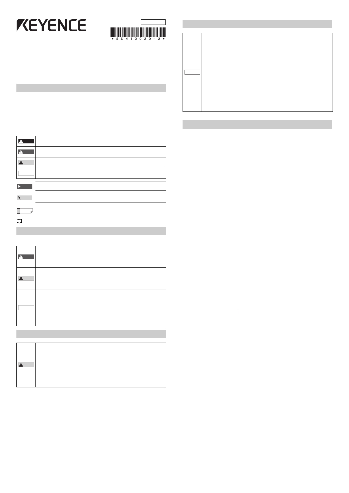
Symbols
The following symbols alert you to important messages. Be sure to read
these messages carefully.
It indicates a hazardous situation which, if not avoided, will result in death or
serious injury.
It indicates a hazardous situation which, if not avoided, could result in death
or serious injury.
It indicates a hazardous situation which, if not avoided, could result in minor
or moderate injury.
It indicates a situation which, if not avoided, could result in product damage
as well as property damage.
It indicates cautions and limitations that must be followed during operation.
It indicates additional information on proper operation.
It indicates tips for better understanding or useful information.
Indicates the reference pages in this manual or the reference pages in separate manuals.
Safety Information for SR-1000 Series
General Precautions
• Do not use this product for the purpose to protect a human body or a part
of human body.
• This product is not intended for use as explosion-proof product. Do not
use this product in hazardous location and/or potentially explosion
atmosphere.
• You must verify that the SR-1000 Series are operating correctly in terms of
functionality and performance before the start and the operation of the
SR-1000 Series.
• We recommend that you take substantial safety measures to avoid any
damage in the event of a problem occurring.
• KEYENCE never warrant the function or performance of the SR-1000
Series if it is used in a manner that differs from the SR-1000 Series
specifications contained in this instruction manual of if the SR-1000
Series are modified by yourself.
• When the SR-1000 Series is used in combination with other instruments,
functions and performance maybe degraded, depending on operating
conditions and the surrounding environment.
• If the equipment is used in a manner not specified by the manufacturer.
the protection provided by the equipment may be impaired.
Safety Precautions on LED Product
• Use of controls or adjustments or performance of procedures other than
those specified herein may result in hazardous radiation exposure.
• Follow the instructions mentioned in this manual. Otherwise, injury to the
human body (eyes and skin) may result.
• Do not stare into the beam.
• Do not disassemble this product.
LED emission from this product is not automatically stopped when it is
disassembled.
• Do not view directly with optical instruments. Viewing the LED output
with certain optical instruments (for example, eye loupes, magnifiers
and microscopes) within a distance of 100 mm may pose an eye hazard.
Precautions on Proper Use
• Do not use a voltage other than that described in the specifications with
the SR-1000 Series. Doing so may cause damage to the unit.
• Be sure to turn off the power to devices attached to the SR-1000 Series
when you plug in or unplug the cables. Failure to do so may cause damage
to the SR-1000 Series.
• Do not disassemble or modify the SR-1000 Series. Doing so may cause
damage to the unit.
• Place cables as far away as possible from high-voltage lines and power
lines. Otherwise, electrical noise can be generated that may cause a
NOTICE
product failure or malfunction.
• The SR-1000 Series is a precision instrument. Do not impact or drop the
instrument. Pay particular attention when transporting or installing the unit.
• Do not carry the SR-1000 Series by holding its cables. This may cause cable
breaks or damage to the unit due to the impact of bumping each other.
• Do not allow water, oil, dust, or other foreign substances to stick to the
scanner. This may cause read errors. Use a soft, dry cloth to wipe any
substance from the scanner. (Do not use a cloth dipped in alcohol or other
cleaning agent.)
• Do not turn off the power of the SR-1000 Series while accessing files. The
internal data may be corrupted.
Precautions on Proper Use
CE Marking
Keyence Corporation has confirmed that this product complies with the
essential requirements of the applicable EC Directive, based on the
following specifications.
Be sure to consider the following specifications when using this product
in the Member State of European Union.
z EMC Directive (2004/108/EC)
• Applicable standards EMI : EN61326-1, Class A
EMS : EN61326-1
• The length of cable connected to the power supply connector must
be less than or equal to 30 m.
• This product is intended to be used in an industrial electromagnetic
environment.
These specifications do not give any guarantee that the end-product with
this product incorporated complies with the essential requirements of
EMC Directive. The manufacturer of the end-product is solely responsible
for the compliance on the end-product itself according to EMC Directive.
z Low-Voltage Directive (2006/95/EC)
• Applicable standard : EN62471
• Indoor use only.
CSA Certificate
This product complies with the following CSA and UL standards and has
been certified by CSA.
• Applicable standard : CAN/CSA C22.2 No.61010-1
UL61010-1
• Be sure to consider the following specifications when using this product
as a product certified by CSA.
• Overvoltage category
• Use this product under pollution degree 2.
• Use this product at the altitude of 2000 m or less.
• Indoor use only.
• When using this product, use the following power supply.
CSA or UL certified power supply that provides Class 2 output as
defined in the CEC (Canadian Electrical Code) and NEC (National
Electrical Code), Or CSA or UL certified power supply that has been
evaluated as a Limited Power Source as defined in CAN/CSA-C22.2
No. 60950-1/UL60950-1.
Radio Waves Act in South Korea
Class A Equipment
This is a class A product. In a domestic environment this product may
cause radio interference in which case the user may be required to take
adequate measures.
Note: This caution is effective for the Korean Radio Act only.
A 급 기기 ( 업무용 방송통신기자재 )
이 기기는 업무용 (A 급 ) 전자파적합기기로서 판매자 또는 사용자는 이
점을주의하시기 바라며 , 가정외의 지역에서 사용하는 것을 목적으로 합
니다 .
1
E SR-1000-IM
Page 2
Package Contents
1
E SR-1000-IM
2D Code Reader (Fixed Type)
SR-1000 Series
Instruction manual
Introduction
Read this instruction manual before using the product in order to achieve
maximum performance.
After reading it, keep the manual always at hand for future reference.
Symbols
The following symbols alert you to important messages. Be sure to read
these messages carefully.
Important
It indicates cautions and limitations that must be followed during operation.
Point
It indicates additional information on proper operation.
Reference
It indicates tips for better understanding or useful information.
Indicates the reference pages in this manual or the reference pages in separate manuals.
Safety Information for SR-1000 Series
General Precautions
Safety Precautions on LED Product
Precautions on Proper Use
Precautions on Proper Use
CE Marking
Keyence Corporation has confirmed that this product complies with the
essential requirements of the applicable EC Directive, based on the
following specifications.
Be sure to consider the following specifications when using this product
in the Member State of European Union.
zEMC Directive (2004/108/EC)
•Applicable standardsEMI : EN61326-1, Class A
EMS: EN61326-1
•The length of cable connected to the power supply connector must
be less than or equal to 30 m.
These specifications do not give any guarantee that the end-product
with this product incorporated complies with the essential
requirements of EMC Directive. The manufacturer of the end-product
is solely responsible for the compliance on the end-product itself
according to EMC Directive.
zLow-Voltage Directive (2006/95/EC)
•Applicable standard :EN62471
•Indoor use only.
CSA Certificate
This product complies with the following CSA and UL standards and has
been certified by CSA.
•Applicable standard : CAN/CSA C22.2 No.61010-1
UL61010-1
•Be sure to consider the following specifications when using this product
as a product certified by CSA.
•Overvoltage category
•Use this product under pollution degree 2.
•Use this product at the altitude of 2000 m or less.
•Indoor use only.
•When using this product, use the following power supply.
CSA or UL certified power supply that provides Class 2 output as
defined in the CEC (Canadian Electrical Code) and NEC (National
Electrical Code), Or CSA or UL certified power supply that has been
evaluated as a Limited Power Source as defined in CAN/CSA-C22.2
No. 60950-1/UL60950-1.
Radio Waves Act in South Korea
Class A Equipment
This is a class A product. In a domestic environment this product may
cause radio interference in which case the user may be required to take
adequate measures.
Note: This caution is effective for the Korean Radio Act only.
Ͳ匏匶匶櫋怺殯愯暧皻柦匶沖沲
決匶匶垚櫋怺殯Ͳ匏洊沖砒洇穯匶匶嵢昢砖廪沖嬖垚斲殯沖垚決
洖汊渂汞穞柢匶愚岂彶儆洛歾汞滆櫳櫖昢斲殯穞垚冉汊徯洇求嵢穯
城埪
It indicates a hazardous situation which, if not avoided, will result in death or
serious injury.
It indicates a hazardous situation which, if not avoided, could result in death
or serious injury.
It indicates a hazardous situation which, if not avoided, could result in minor
or moderate injury.
It indicates a situation which, if not avoided, could result in product damage
as well as property damage.
•Do not use this product for the purpose to protect a human body or a part
of human body.
•This product is not intended for use as explosion-proof product. Do not
use this product in hazardous location and/or potentially explosion
atmosphere.
•You must verify that the SR-1000 Series are operating correctly in terms of
functionality and performance before the start and the operation of the
SR-1000 Series.
•We recommend that you take substantial safety measures to avoid any
damage in the event of a problem occurring.
•KEYENCE never warrant the function or performance of the SR-1000
Series if it is used in a manner that differs from the SR-1000 Series
specifications contained in this instruction manual of if the SR-1000
Series are modified by yourself.
•When the SR-1000 Series is used in combination with other instruments,
functions and performance maybe degraded, depending on operating
conditions and the surrounding environment.
•Use of controls or adjustments or performance of procedures other than
those specified herein may result in hazardous radiation exposure.
•Follow the instructions mentioned in this manual. Otherwise, injury to the
human body (eyes and skin) may result.
•Do not stare into the beam.
•Do not disassemble this product.
LED emission from this product is not automatically stopped when it is
disassembled.
•Do not view directly with optical instruments. Viewing the LED output
with certain optical instruments (for example, eye loupes, magnifiers
and microscopes) within a distance of 100 mm may pose an eye hazard.
96M13020
DANGER
WARNING
CAUTION
NOTICE
WARNING
CAUTION
NOTICE
CAUTION
•Do not use a voltage other than that described in the specifications with
the SR-1000 Series. Doing so may cause damage to the unit.
•Be sure to turn off the power to devices attached to the SR-1000 Series
when you plug in or unplug the cables. Failure to do so may cause damage
to the SR-1000 Series.
•Do not disassemble or modify the SR-1000 Series. Doing so may cause
damage to the unit.
•Place cables as far away as possible from high-voltage lines and power
lines. Otherwise, electrical noise can be generated that may cause product
failure or malfunction.
•The SR-1000 Series is a precision instrument. Do not impact or drop the
instrument. Pay particular attention when transporting or installing the unit.
•Do not carry the SR-1000 Series by holding its cables. This may cause cable
breaks or damage to the unit due to the impact of bumping each other.
•Do not allow water, oil, dust, or other foreign substances to stick to the
scanner. This may cause read errors. Use a soft, dry cloth to wipe any
substance from the scanner. (Do not use a cloth dipped in alcohol or other
cleaning agent.)
•Do not turn off the power of the SR-1000 Series while accessing files. The
internal data may be corrupted.
NOTICE
SR-1000
POWER
USB
ETHER
NET
SR
1000
SEL
MENU
(1)
(2)
(3)
(4)
(5)
(6)
(7)
(8)
To p
Bottom
DC24V
Brown
Blue
Black tube
FG
TEST MODE
1 2 3 4 5
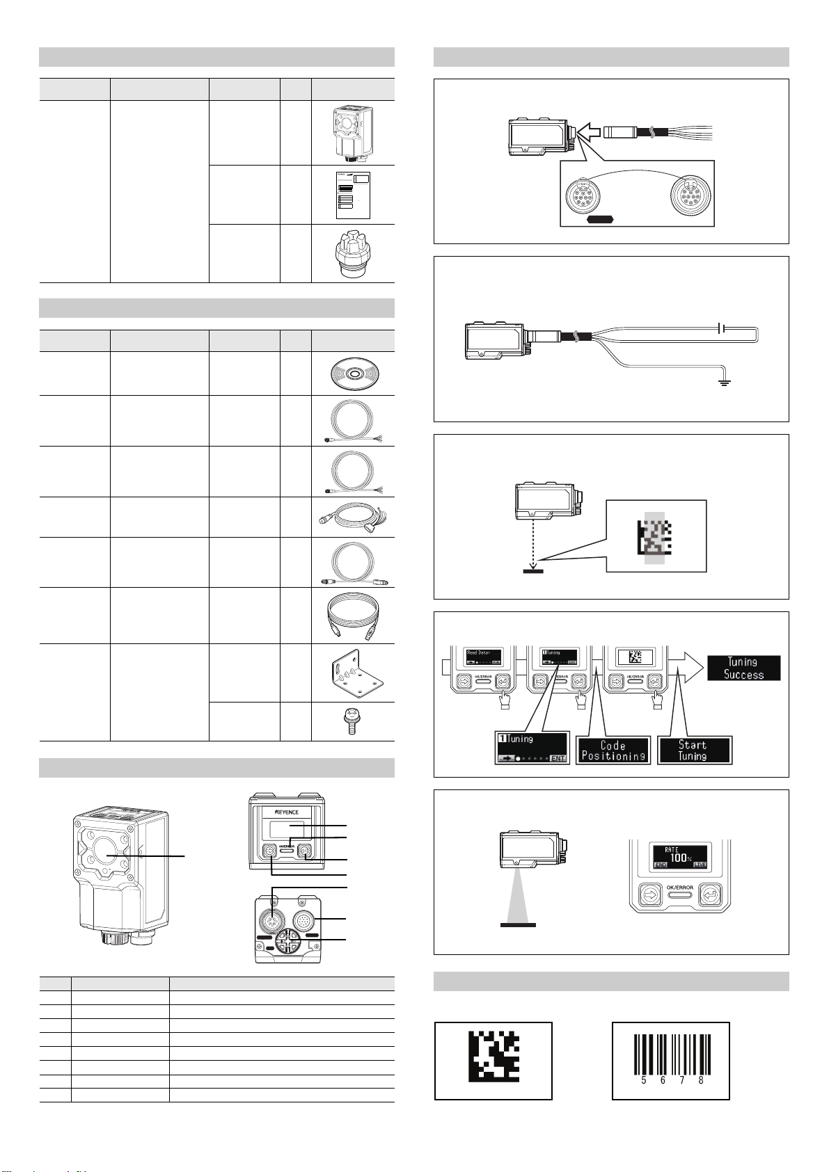
Startup Procedure
Model Name
SR-1000/1000W Auto focus code reader
(Fixed type)
Option
Model Name
SR-H4W Setup software
OP-87224/
87225/87226
OP-87353/87354/
87355
(AutoID Network
Navigator)
Control cable Cable
Control cable
(NFPA-compliant)
Package
content
Reader unit 1
Instruction
manual
Ethernet port
cover
Package
content
DVD-ROM 1
(2 m/5 m/10 m)
Cable
(2 m/5 m/10 m)
Qty. Appearance
SEL
M
E
N
U
SR
1000
Step 1
1
1
Step 2
Qty. Appearance
1
1
Step 3
POWER
OP-87527/87528/
87529
Control cable
(NFPA-compliant)
Cable
(2 m/5 m/10 m)
D-sub connector type
OP-87230/87231/
87232
OP-51580 USB cable Cable
Ethernet cable
(NFPA-compliant)
Cable
(2 m/5 m/10 m)
(2 m)
OP-87866 Mounting bracket Mounting
bracket
Screw (M4) 4
Part Names and Functions
1
1
1
Step 4
1
Step 5
No. Name Description
(1) Scanner Section that reads codes.
(2) Display Shows reading results or reading data.
(3) OK/ERROR LED IIndicates whether the reading has succeeded or failed
(4) ENTER button Button used to confirm functions.
(5) SELECT button Button used to select functions.
(6) Control port Port for connecting the control cable.
(7) Ethernet port Port for connecting the Ethernet cable.
(8) USB port Port for connecting the USB cable for setting.
E SR-1000-IM
Sample Code
DataMatrix CODE128
2
Page 3

Connection and Wiring
Screw tightening torque:
1.5 to 2.0 N·m
SR
1000
SEL
MENU
Brown 24 V
24 VDC
0 V
FG
Blue
Black tube
S
R
1000
SEL
MENU
Brown
Load
Pink/
Light blue/White
White and blue
Green/Gray
Black
Blue
Black tube
24 VDC
FG
0 V
OUT COM
IN1 to 2
IN COM
OUT1 to 3
24 V
SR
1000
SEL
MENU
Load
24 VDC
Blue
Black tube FG
0 V
Black
OUT COM
Green/Gray IN1 to 2
White and blue IN COM
Pink/
Light blue/White
OUT1 to 3
Brown 24 V
Screw tightening torque:
0.8 to 1.0 N·m
POWER
USB
ETHER
NET
Connecting the control cable and wiring
1 Align the protrusion in the cable connector with the notch in the
control port.
2 Tighten the connector screw by turning it clockwise.
3 Connect the wires according to the usage.
z When the I/O terminals are not used
Wire color Name Description
Signal
direction
Initial assignment AWG
Brown 24 V 24 VDC Input - 26
Blue 0 V Power GND - - 26
Orange RXD (RD) RS-232C Receive Input - 28
Yellow TXD (SD) RS-232C Send Output - 28
Purple SGND RS-232C GND - - 28
Green IN1 Input signal 1 Input Reading start 26
Gray IN2 Input signal 2 Input - 28
White and
IN COM Input common - - 28
blue
Pink OUT1 Output signal 1 Output Reading OK 28
Light blue OUT2 Output signal 2 Output Reading ERROR 28
White OUT3 Output signal 3 Output BUSY 28
Black OUT COM Output common - - 28
Black tube FG Frame ground - - -
• Be sure to turn power off before attempting to connect or disconnect the
control cable.
• Insert the connector straight so that it is not tilted and then tighten it
securely. Under-tightening can lead to a loose connector due to
vibrations, resulting in poor contact.
* After tightening it as much as possible by hand, tighten it further
NOTICE
approximately 90° - 120° using a tool such as pliers.
• Insulate unused wires individually.
• Be sure to provide Class D ground for the FG wire.
• The shield and FG wires of the control cable and the shield wire of the
Ethernet cable are electrically connected via the main unit housing. Be
sure to provide them with a common ground.
Connecting the Ethernet cable
1 Align the protrusion in the cable connector with the notch in the
Ethernet port and connect the cable to the main unit.
z NPN wiring
z PNP wiring
2 Tighten the connector screw by turning it clockwise.
The screw tightening torque should be within the range between 0.8 and
1.0 N·m.
• When connecting the connector, insert it so that it does not tilt, and then
push in and tighten the connector securely. Under-tightening can lead to a
loose connector due to vibrations, resulting in poor contact.
• After tightening it as much as possible by hand, tighten it further
NOTICE
approximately 5° - 10° using a tool such as pliers.
• Do not bend the base of the Ethernet cable connector repeatedly. It may
cause connection failure.
Connecting the USB cable
1 Confirm the orientation and insert the connector straight so that it is
not tilted.
When connecting the connector, insert it straight so it does not tilt.
NOTICE
Otherwise, the connector pin may be damaged.
3
E SR-1000-IM
Page 4

View and Installation Distance
SR
-
1000
SEL
MENU
View V
Installation distance
• 1280 × 1024 (pixels)
View V = View H × 0.80 (H:V = 5:4)
• 800 × 600 (pixels)
View V = View H × 0.75 (H:V = 4:3)
View H
350
300
250
200
150
100
50
0
0 100 200 300 400 500 600 700 800 900 1000 1100
1280x1024
800x600
View H (mm)
Distance (mm)
700
600
500
400
300
200
100
0
0 100 200 300 400 500 600 700 800 900 1000 1100
1280x1024
800x600
View H (mm)
Distance (mm)
NOTICE
SR
100
0
SEL
MENU
Mounting bracket
The SR-1000 Series provides different installation distances to the target and
view sizes depending on the type of the reader. Confirm the type of the
reader to be used and its view.
SR-1000 (Standard type)
Minimum Resolution (Typical)
• SR-1000
Unit: mm
Distance 2D code Barcode Distance 2D code Barcode
110 0.063 - 50 0.082 -
110 to 140 0.082 - 50 to 100 0.14 0.082
110 to 230 0.14 0.082 50 to 150 0.20 0.12
110 to 300 0.18 0.11 50 to 230 0.30 0.18
110 to 400 0.24 0.15 50 to 300 0.38 0.23
110 to 600 0.37 0.22 50 to 400 0.51 0.31
110 to 1000 0.61 0.37 50 to 600 0.76 0.45
• SR-1000W
Mounting
1 Secure the SR-1000 Series unit with screws.
Mounting screws are not included.
SR
1000
SEL
MENU
Unit: mm
Typical
Distance
110 30 24 19 14
1000 312 250 195 146
1280 x 1024 (pixel) 800 x 600 (pixel)
Horizontal Ver tical Horizontal Vertical
SR-1000W (Wide-view type)
• Mounting screw size : M4
• Tightening torque : 0.5N·m
• Screw hole depth of the SR-1000 Series : 5 mm
Mounting by Using the Optional Mounting Bracket (OP-87866)
1 Attach the optional mounting bracket to the SR-1000 Series.
Unit: mm
• Mounting bracket : M4
• Supplied screw size : 0.5N·m
2 Secure the mounting bracket.
Mounting screws are not included.
Typical
Distance
50 35 28 22 16
600 384 307 240 180
E SR-1000-IM
The distances or angles that can be used for reading may vary according to
the print quality and size of the code to be read or surrounding environment.
Use the test mode, etc. to confirm the most appropriate mounting condition
in the environment.
1280 x 1024 (pixel) 800 x 600 (pixel)
Horizontal Ver tical Horizontal Vertical
Unit: mm
• Mounting screw size : M5
4
S
E
L
M
E
NU
SR
1000
Page 5

Specifications
Model SR-1000 SR-1000W
Typ e Standard Wide range
Receiver
Light emitter
Focus adjustment Automatic*
Reading specifications
I/O specifications
Environmental resistance
Rating
Weight Approx. 200 g
*The focus position can be automatically adjusted during installation and during tuning.
Sensor CMOS Image Sensor
Number of pixels 1280 x 1024 pixels
Light source High-intensity red LED
Pointer light source High-intensity green LED
Supported symbol
Minimum resolution
Reading distance 110 mm to 1000 mm 50 mm to 600 mm
Reading view range (at a distance of 400 mm) 122 mm x 97 mm 257 mm x 206 mm
Control input
Control output
Ethernet
Serial communication
USB Communication standard USB 2.0 Full Speed compliant
Enclosure rating IP65
Ambient temperature 0 to 45°C
Ambient storage temperature -10 to +50°C
Relative humidity 35 to 85% RH (No condensation)
Storage ambient humidity 35 to 85% RH (No condensation)
Ambient light Sunlight: 10000 lux, Incandescent lamp: 6000 lux, Fluorescent lamp: 2000 lux
Operating environment No dust or corrosive gas present
Vibration 10 to 55 Hz Double amplitude 0.75 mm, 3 hours each in X, Y and Z directions
Power supply voltage 24 VDC±10%
Current consumption 700 mA
2D code
Barcode
2D code 0.063 mm 0.082 mm
Barcode 0.082 mm 0.082 mm
Points 2
Input type Bidirectional voltage input
Maximum rating 26.4 VDC
Minimum ON voltage 15 VDC
Maximum OFF current 0.2 mA or less
Points 3
Output type Photo MOS relay output
Maximum rating 30 VDC
Maximum load current 1 output: 50 mA or less, 3-output total: 100 mA or less
Leakage current when OFF 0.1 mA or less
Residual voltage when ON 1 V or less
Communication standard IEEE 802.3 compliant, 10BASE-T/100BASE-TX
Supported protocol TCP/IP, SNTP, FTP, BOOTP, EtherNet/IP, PROFINET, KV STUDIO, MC Protocol, OMRON PLC Link
Communication standard RS-232C compliant
Communication speed 9600, 19200, 38400, 57600, 115200 bps
Supported protocol None, KV STUDIO, MC Protocol, SYSWAY
GS1 DataBar, CODE39, CODE39 FullASCII, Trioptic CODE39, CODE93, CODE128, GS1-128,
JAN/EAN/UPC, ITF, NW-7 (Codabar), 2of5 (Industrial 2of5), COOP 2of5, Pharmacode
QR, MicroQR, DataMatrix (ECC200), GS1 DataMatrix
PDF417, Micro PDF417, GS1 Composite (CC-A, CC-B, CC-C)
5
E SR-1000-IM
Page 6

Dimensions
4×M4
Depth: 5
152
180
120123
120
123
20.5
38.5 2.6
47.6
18.9
28
74
17
47
28
Unit: mm
33
7.5
28
28
(5)
47
2
52
50.5
10°
10°
φ5.3
R32
5.3
Unit: mm
10000
5000
2000
φ6.7
45
φ15
1205
150
5
180
5
Unit: mm
Thickness: 16
150
180
120
45
36.8
26
38
2000
5000
10000
φ6.7
φ15
180 mm Brown, blue, black tube
150 mm Black, pink, light blue, white
120 mm Gray, green, white and blue
Unit: mm
2000
5000
10000±50
51.3 47
φ6.5
φ15
14.7
Unit: mm
Copyright (c) 2014 KEYENCE CORPORATION. All rights reserved.
13020E 1025-2 96M13020 Printed in Japan
SR-1000/1000W
When the mounting bracket (OP-87866) is used
OP-87224/87225/87226/87353/87354/87355
WARRANTIES AND DISCLAIMERS
(1) KEYENCE warrants the Products to be free of defects in materials and workmanship
for a period of one (1) year from the date of shipment. If any models or samples were
shown to Buyer, such models or samples were used merely to illustrate the general
type and quality of the Products and not to represent that the Products would
necessarily conform to said models or samples. Any Products found to be defective
must be shipped to KEYENCE with all shipping costs paid by Buyer or offered to
KEYENCE for inspection and examination. Upon examination by KEYENCE,
KEYENCE, at its sole option, will refund the purchase price of, or repair or replace at
no charge any Products found to be defective. This warranty does not apply to any
defects resulting from any action of Buyer, including but not limited to improper
installation, improper interfacing, improper repair, unauthorized modification,
misapplication and mishandling, such as exposure to excessive current, heat,
coldness, moisture, vibration or outdoors air. Components which wear are not
warranted.
(2) KEYENCE is pleased to offer suggestions on the use of its various Products. They are
only suggestions, and it is Buyer's responsibility to ascertain the fitness of the
Products for Buyer’s intended use. KEYENCE will not be responsible for any
damages that may result from the use of the Products.
(3) The Products and any samples ("Products/Samples") supplied to Buyer are not to be
used internally in humans, for human transportation, as safety devices or fail-safe
systems, unless their written specifications state otherwise. Should any Products/
Samples be used in such a manner or misused in any way, KEYENCE assumes no
responsibility, and additionally Buyer will indemnify KEYENCE and hold KEYENCE
harmless from any liability or damage whatsoever arising out of any misuse of the
Products/Samples.
(4) OTHER THAN AS STATED HEREIN, THE PRODUCTS/SAMPLES ARE PROVIDED
WITH NO OTHER WARRANTIES WHATSOEVER. ALL EXPRESS, IMPLIED, AND
STATUTORY WARRANTIES, INCLUDING, WITHOUT LIMITATION, THE
WARRANTIES OF MERCHANTABILITY, FITNESS FOR A PARTICULAR
PURPOSE, AND NON-INFRINGEMENT OF PROPRIETARY RIGHTS, ARE
EXPRESSLY DISCLAIMED.
IN NO EVENT SHALL KEYENCE AND ITS AFFILIATED ENTITIES BE LIABLE TO
ANY PERSON OR ENTITY FOR ANY DIRECT, INDIRECT, INCIDENTAL,
PUNITIVE, SPECIAL OR CONSEQUENTIAL DAMAGES (INCLUDING, WITHOUT
LIMITATION, ANY DAMAGES RESULTING FROM LOSS OF USE, BUSINESS
INTERRUPTION, LOSS OF INFORMATION, LOSS OR INACCURACY OF DATA,
LOSS OF PROFITS, LOSS OF SAVINGS, THE COST OF PROCUREMENT OF
SUBSTITUTED GOODS, SERVICES OR TECHNOLOGIES, OR FOR ANY MATTER
ARISING OUT OF OR IN CONNECTION WITH THE USE OR INABILITY TO USE
THE PRODUCTS, EVEN IF KEYENCE OR ONE OF ITS AFFILIATED ENTITIES
WAS ADVISED OF A POSSIBLE THIRD PARTY’S CLAIM FOR DAMAGES OR
ANY OTHER CLAIM AGAINST BUYER. In some jurisdictions, some of the foregoing
warranty disclaimers or damage limitations may not apply.
BUYER'S TRANSFER OBLIGATIONS:
If the Products/Samples purchased by Buyer are to be resold or delivered to a third
party, Buyer must provide such third party with a copy of this document, all
specifications, manuals, catalogs, leaflets and written information provided to Buyer
pertaining to the Products/Samples.
E 1101-3
OP-87527/87528/87529
OP-87230/87231/87232
Cautions
(1) Unauthorized reproduction of this manual in whole or part is prohibited.
(2) The contents of this manual may be changed for improvements without
prior notice.
(3) An utmost effort has been made to ensure the contents of this manual are
as complete as possible. If there are any mistakes or questions, please
contact a KEYENCE office listed in the back of the manual.
(4) Regardless of item (3), KEYENCE will not be liable for any effect resulting
from the use of this unit.
(5) Any manuals with missing pages or other paging faults will be replaced.
 Loading...