

Page 1
96M13270
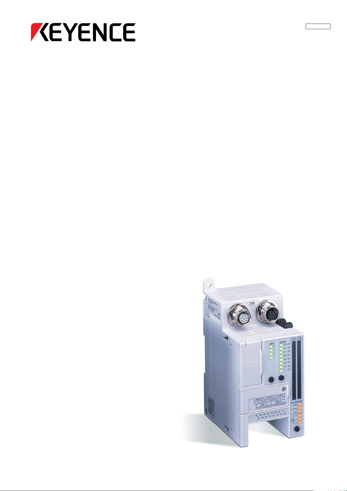
IntelligentExtensionUnit
SL-R12EX
InstructionManual
NOTICE
Do not attempt to operate or service this machine
until you have read and understand the
instructions written in this manual.
Page 2

Contents
Safety Precautions
1. Safety Headings .........................................................................................................................................iii
2. General Precautions .................................................................................................................................. iii
3. Warning .......................................................................................................................................................iv
4. Circuit Design and Wiring ........................................................................................................................... v
5. Testing and Maintenance ............................................................................................................................ v
6. About Standards and Regulations ........................................................................................................... vi
7. Accessories ................................................................................................................................................vi
1 Specifications
1-1 Part Names .......................................................................................................................................... 1-2
1-2 Specifications ..................................................................................................................................... 1-3
1-3 External Dimensions Diagram .......................................................................................................... 1-5
1-4 Power Supply Precautions ................................................................................................................ 1-6
1-4-1 Power Units that Can Be Used as Power Supplies for SL-C Series and SL-R11/SL-R12EX ..... 1-6
1-4-2 Recommended Dedicated Power Supply Unit ............................................................................ 1-6
2 Functions
2-1 Foreword ............................................................................................................................................. 2-1
2-2 Floating blanking function................................................................................................................. 2-1
2-2-1 Floating blanking for 1 beam axis ............................................................................................... 2-1
2-2-2 Floating blanking for 2 beam axes .............................................................................................. 2-2
2-2-3 Floating blanking for 3 beam axes .............................................................................................. 2-2
2-3 Fixed blanking function ..................................................................................................................... 2-2
2-4 Blanking blind protection function ................................................................................................... 2-3
2-5 Muting function .................................................................................................................................. 2-3
2-5-1 Muting function ........................................................................................................................... 2-3
2-5-2 Two-input muting ......................................................................................................................... 2-8
2-5-3 Four-input muting ........................................................................................................................ 2-9
2-5-4 Two-input programmable muting function ................................................................................. 2-12
2-5-5 Four-input programmable muting function ................................................................................ 2-14
2-6 Use of function combinations ......................................................................................................... 2-17
2-7 Status monitor .................................................................................................................................. 2-18
3 Mounting and Installation
3-1 Installation Location .......................................................................................................................... 3-1
3-2 Installation Using a DIN Rail .............................................................................................................. 3-1
3-3 Wall Mounting Using Screws ............................................................................................................ 3-3
3-4 Connection to the SL-U2 and the SL-R11 Recommended Dedicated Power Supply ................... 3-3
ENGLISH
English
i
Page 3

4 Wiring and setting
4-1 When not using the unit's blanking and muting features............................................................... 4-1
4-1-1 Setting procedure ....................................................................................................................... 4-1
4-2 Floating blanking function................................................................................................................. 4-2
4-2-1 Setting procedure ....................................................................................................................... 4-2
4-3 Fixed blanking function ..................................................................................................................... 4-3
4-3-1 Setting procedure ....................................................................................................................... 4-3
4-4 Blanking blind protection function ................................................................................................... 4-4
4-4-1 Blanking blind protection unit ...................................................................................................... 4-4
4-4-2 Installing the blanking blind protection (BBP) unit and the SL-C Series ..................................... 4-5
4-4-3 Obstacle restrictions .................................................................................................................. 4-7
4-4-4 Connecting the blanking blind protection (BBP) unit and the SLR-12EX.................................... 4-8
4-4-5 Setting procedure ....................................................................................................................... 4-8
4-5 Muting function ................................................................................................................................ 4-10
4-5-1 Muting devices .......................................................................................................................... 4-10
4-5-2 Muting lamps ............................................................................................................................ 4-12
4-5-3 Setting procedure for two-input muting function ....................................................................... 4-15
4-5-4 Setting procedure for four-input muting function ....................................................................... 4-16
4-5-5 Bank switching input devices .................................................................................................... 4-17
4-5-6 Setting procedure for two-input programmable muting function ............................................... 4-18
4-5-7 Setting procedure for four-input programmable muting bank function ...................................... 4-19
4-6 Combinations of functions .............................................................................................................. 4-21
4-6-1 Combination between the Floating blanking function and the Fixed blanking function ............ 4-21
4-6-2
Combination between the Floating blanking function and the Blanking blind protection function ...
4-6-3 Combination between the Floating blanking function and the Muting function ......................... 4-22
4-6-4 Combination between the Fixed blanking function and the Muting function ............................. 4-22
4-6-5 Combination between the Fixed blanking function and the Programmable muting function .... 4-22
4-6-6 Combination between the Blanking blind protection function and the Muting function ............. 4-23
4-6-7
Combination between the Blanking blind protection function and the Programmable muting function ...
4-6-8
Combination between the Floating blanking function, the Fixed blanking function, and the Muting function ...
4-6-9
Combining the Floating blanking function, the Blanking blind protection function, and the Muting function ...
4-7 Status monitor .................................................................................................................................. 4-25
4-7-1 The UNIT indicator .................................................................................................................... 4-25
4-7-2 The BEAM indicator .................................................................................................................. 4-26
4-7-3 Other indicators ........................................................................................................................ 4-27
4-8 Status Display (SL-R12D) ................................................................................................................ 4-28
4-8-1 Indicators on SL-R12D ............................................................................................................. 4-28
4-8-2 Installing the SL-R12D onto a panel ......................................................................................... 4-29
4-8-3 Connection method ................................................................................................................... 4-30
4-21
4-23
4-24
4-24
5 Checklist
5-1 List of Pre-use check Items ............................................................................................................... 5-1
5-1-1 Checking the SL-R12EX installation conditions .......................................................................... 5-1
5-1-2 Checking wiring .......................................................................................................................... 5-1
5-2 List of maintenance check items ...................................................................................................... 5-2
6 Troubleshooting
Troubleshooting .................................................................................................................................... 6-1
7 Revision History
Revision History .................................................................................................................................. 7-1
96M13270
ENGLISH
ii
Page 4
Safety Precautions
This manual describes handling, operation, and precautionary information for the Intelligent Extension Unit
(SL-R12EX). Read this manual thoroughly before operating the SL-R12EX in order to understand device
features, and keep this instruction manual readily available for reference.
1. Safety Headings
This instruction manual uses the following headings to display important safety information. Strict adherence
to the instructions next to these headings is required at all times.
DANGER
WARNING
CAUTION
Important:
Note:
Tips
➮
Reference:
WARNING
Failure to follow the instructions may lead to death or serious injury.
Failure to follow the instructions may result in significant harm to machine operators, including death.
Failure to follow the instructions may result in failure to the SL-R12EX, or to the
machine to which it is installed.
Provides important precautions and restrictions for proper operation.
Provides additional information for proper operation.
Provides useful information for proper operation.
Provides reference pages.
The SL-R12EX is a special controller unit for the Safety Light Curtain SL-C Series
and the Intelligent Safety Relay Unit SL-R11.
Therefore, be sure to refer to and strictly observe the precautions and warnings
written in the SL-C Series and/or SL-R11 Instruction Manual.
2. General Precautions
ENGLISH
English
•Verify that this device is operating normally in terms of functionality and performance before the start of
work and before the start of device operation.
• KEYENCE is unable to warrant the function or performance of the SL-R12EX if it is used in a manner that
differs from the SL-R12EX specifications contained in this instruction manual or if the SL-R12EX is modified.
• When using the SL-R12EX to protect machine operators from a hazardous zone or a hazard, or using it
as safety equipment for any purpose, always follow the applicable requirements, regulations, and laws
(collectively “regulations”) existing in the country or region where the SL-R12EX is being used. For such
regulations, contact directly the regulatory agency responsible for occupational safety and health in your
country or region.
• Depending on the type of machine to which the SL-R12EX is to be attached, there may be special safety
regulations related to the use, installation, maintenance, and operation of the device, and such safety
regulations must be followed. The responsible personnel must install the SL-R12EX in strict compliance
with such safety regulations.
• The responsible personnel must train the assigned personnel for the correct use, installation, maintenance, and operation of the SL-R12EX. “Machine operators” refers to personnel who have received
appropriate training from the responsible personnel and are qualified to operate the device correctly.
• Machine operators must receive specialized training for the SL-R12EX and must understand and follow
the safety regulations for the country or region in which they are using the SL-R12EX.
• When the SL-R12EX fails to operate properly, machine operators must immediately stop the use of the
device and report this fact to the responsible personnel.
• The SL-R12EX is designed with the assumption that it would be properly installed in accordance with the
installation procedures described in this instruction manual and operated according to the instructions in
this instruction manual. Perform an appropriate installation of the SL-R12EX after conducting a sufficient
risk assessment for the target machine.
• This device should be processed as an industrial waste product when being disposed.
iii
Page 5

3. Warning
■ Operators
• In order for the SL-R12EX to operate properly, the responsible personnel and machine operators must
follow all procedures described in this instruction manual.
• No person other than the responsible personnel and machine operators should be allowed to install or
test the SL-R12EX.
• When performing electrical wiring, always follow electrical standards and regulations for the country or
region in which the SL-R12EX is being used.
■ Usage environment
• Do not use the device in an environment (temperature, humidity, interfering light, etc.) that does not
conform to the specifications contained in this instruction manual.
• Do not use wireless devices such as cellular phones or transceivers in the vicinity of the SL-R12EX.
• The SL-R12EX is not designed to be explosion-proof. Never use it in the presence of flammable or
explosive gases or elements.
• Do not use the SL-R12EX in the presence of substances, such as heavy smoke, particulate matter, or
corrosive chemical agents, that may induce deterioration in product quality.
■ Target machine
• The SL-R12EX has not undergone the model certification examination in accordance with Article 44-2
of the Japanese Industrial Safety and Health Law. The SL-R12EX, therefore, cannot be used in Japan
as a “Safety Device for Press and Shearing machines” as established in Article 42 of that law.
• The machine on which the SL-R12EX is to be installed must be susceptible to an emergency stop at all
operating points during its operation cycle. Do not use the SL-R12EX for machines with irregular stop
times.
• Do not use the SL-R12EX for power presses equipped with full-revolution clutches.
• Do not use the SL-R12EX to control (stop forward motion, etc.) trains, cars and other transportation
vehicles, aircraft, equipment for use in space, medical devices, or nuclear power generation systems.
• The SL-R11 is designed to protect people or objects from entering a machine’s hazardous zone or
hazard. It cannot provide protection against objects or materials that are displaced from the machine's
hazardous zone or hazard, and so implement additional safety measures such as installing safeguards
when there is the possibility of such displacements.
■ Installation
• Install the SL-R12EX inside an enclosure such as a control panel that offers a rating of at least IP54 in
accordance with the IEC 60529 standard.
• The SL-R12EX is a special controller unit for the Safety Light Curtain SL-C Series and the Intelligent
Safety Relay Unit SL-R11, so be sure to connect it to the SL-C Series and SL-R11 when using it.
• The SL-C**L Series with the detection capability of ø45 mm (1.77") cannot be used in combination with
the SL-R12EX.
■ Function
• When floating blanking function is carried out, the SL-C series cannot keep the original detection
capability. The detection capability of the SL-C**F Series varies among ø14 mm (0.55"), ø24 mm
(0.94"), ø34 mm (1.33"), and ø44 mm (1.73") according to the exact settings used. The detection
capability of the SL-C**H Series varies among ø25 mm (0.98"), ø45 mm (1.77"), ø65 mm (2.56"), and
ø85 mm (3.35") according to the exact settings used. Therefore you must accurately calculate the new
safety distance and install the SL-C Series at the minimum safety distance separately from the
hazardous zone or hazards.
• When fixed blanking function is carried out, it may create a hazardous zone allowing human approach
between the obstacle and the SL-C Series against which the SL-C Series provides no protection. Be
sure to install additional safety protective equipment.
• Enabling the blanking blind protection function does not necessarily remove all hazardous zones
allowing human approach. Depending on the target machine, installation of the blanking blind protection
unit may result in the creation of one or more hazardous zones allowing human approach. Be sure to
read “4-4 Blanking blind protection function” (➮4-4) in this manual before installing or using this unit.
This function can only be used in the SL-C**H Series with the detection capability of ø25 mm (0.98").
• The muting function deactivates the light curtain's safety functions while the light curtain detects the
input signal from one or more muting devices (sensors, switches, etc.). The muting devices (sensors,
switches, etc.) that are used to carry out the muting function as well as the method to install them must
satisfy all the conditions described in this instruction manual as well as the applicable requirements
imposed by all laws, regulations, standards, and ordinances in effect in the country and region where
the SL-R12EX is to be used. Failure to follow this warning results in significant harm to machine operators, including serious injury or death.
ENGLISH
iv
Page 6

• The following conditions must be considered before installing muting devices (sensors, switches, etc.) to
carry out the muting function.
1. The muting function of the light curtain is only permitted during the nonhazardous portion of the
machine cycle.
2. Muting devices must not get active and the light curtain (SL-C Series) must not go to the muting state
even if a person inadvertently approaches the light curtain's detection zone.
• Setting the muting function and muting device configuration must be restricted to an extremely limited
number of the responsible personnel.
• Any personnel other than the responsible personnel must not easily change the position at which the
muting devices are installed. When the muting devices are moved, the procedure must require the
use of specialized tools and must be performed under the responsibility of the responsible personnel.
• Customers who carry out the muting function bear sole responsibility for complying with the requirements imposed on that function. KEYENCE makes no guarantee regarding damage arising from installation, orientation, usage, or maintenance not in accordance with what is described in this instruction
manual, or from the failure to follow all applicable legal regulations in effect in the country and region in
which the SL-R12EX is used.
• The muting lamp or the SL-R12D must be installed prior to carrying out the muting function on the SL-C
Series. The muting lamp or the SL-R12D must be installed at the location where it can always be clearly
and easily visible for the machine operators or the responsible personnel in case of normal machine
operation, setting or alignment for muting or maintenance, etc.
• If it is necessary to install 2 or more muting lamps in order to satisfy the above requirements, the muting
lamps must be installed so that they are connected in series to the LAMP terminal on the SL-R12EX
terminal block. The SL-R12D cannot be used with the other muting lamps simultaneously. Therefore,
the other muting lamps must be installed instead of using the SL-R12D.
ENGLISH
English
4. Circuit Design and Wiring
• Always turn off the device power when performing electrical wiring.
• Follow electrical standards and regulations for the country or region in which the SL-R12EX is being used
when performing the electrical wiring. Only qualified persons should perform wiring.
• Do not place any cables or electrical lines used in wiring the SL-R12EX in the same duct as high-voltage
electrical or power lines or in parallel with such lines.
• The length of the cables from the blanking blind protection unit (SL-C08SB/SL-C16SB) transmitter and
receiver to the SL-R12EX must not exceed 30 m (98.43 ft.).
5. Testing and Maintenance
• Always perform testing in accordance with the test procedures after maintenance, adjustment, or calibration of the target machine or the SL-R12EX, and before the machine start-up.
• If the SL-C, SL-R11 or SL-R12EX does not operate properly when tested in accordance with the test
procedures established in this instruction manual, do not operate the machine.
• Periodically examine the machine to verify that all brakes, other stop mechanisms, and control devices
operate reliably and accurately in addition to checking for SL-C, SL-R11 and SL-R12EX.
• The responsible personnel must perform maintenance procedures as established in this instruction
manual at least once every six months to ensure safe device operation.
v
Page 7

6. About Standards and Regulations
1) The SL-C Series and SL-R11/SL-R12EX comply with the following UL (Underwriters Laboratories
Inc.) Standards and have received Canada-U.S.-Listing certification from UL.
• UL61496-1 (Type 4 ESPE - Electro-Sensitive Protective Equipment)
• UL61496-2 (Type 4 AOPD - Active Opto-Electronic Protective Device)
2) The SL-C Series and SL-R11/SL-R12EX have not received the model certification examination in
accordance with Article 44-2 of the Japanese Industrial Safety and Health Law. As a result, the SLC Series and SL-R11/SL-R12EX cannot be used in Japan as a “Safety Devices for Presses and
Shearing machines” as established in Article 42 of that law.
3) The SL-C Series and SL-R11/SL-R12EX have been designed in consideration of the following
standards and regulations. For details regarding the following standards, contact the third-party
certification organization, such as UL.
<Corresponding standards>
• OSHA 29 CFR 1910.212
• OSHA 29 CFR 1910.217
• ANSI B11.1 - B.11.19
• “Guidelines for Comprehensive Safety Standards of Machinery”, July 31, 2007, number 0731001 issued
by, Ministry of Health, Labor, and Welfare in Japan.
7. Accessories
Confirm that the package includes the main unit (SL-R12EX) and following accessories.
Instruction Manual (this manual) 1 copy
ENGLISH
vi
Page 8

ENGLISH
English
vii
Page 9
Chapter 1 Specifications
1 Specifications
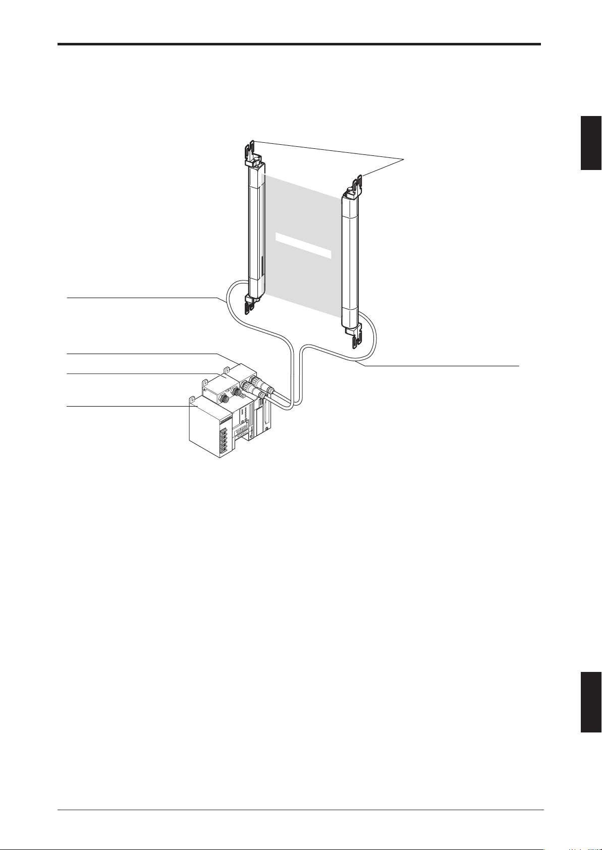
Composition
SL-C Series+ SL-R11 (Intelligent Safety Relay Unit) + SL-R12EX (Intelligent Extension Unit) + SL-U2
(Dedicated power supply unit)
SL-PC5P (5m (16.4 ft.)) cable for transmitter (gray)
* 10 m (32.81 ft.) SL-PC10P cable
SL-R11 intelligent safety relay unit
SL-R12EX intelligent extension unit
SL-U2 dedicated power supply unit
SL-C Series
1
Detection zone
SL-PC5P (5m (16.4 ft.)) cable for receiver (black)
* 10 m (32.81 ft.) SL-PC10P cable
T R
SL-U2: The UL certified, recommended dedicated power supply unit
* The SL-C**L Series with the detection capability of ø45 mm (1.77") cannot be used in combination with
the SL-R12EX.
ENGLISH
1-1
Page 10
1
Chapter 1 Specifications
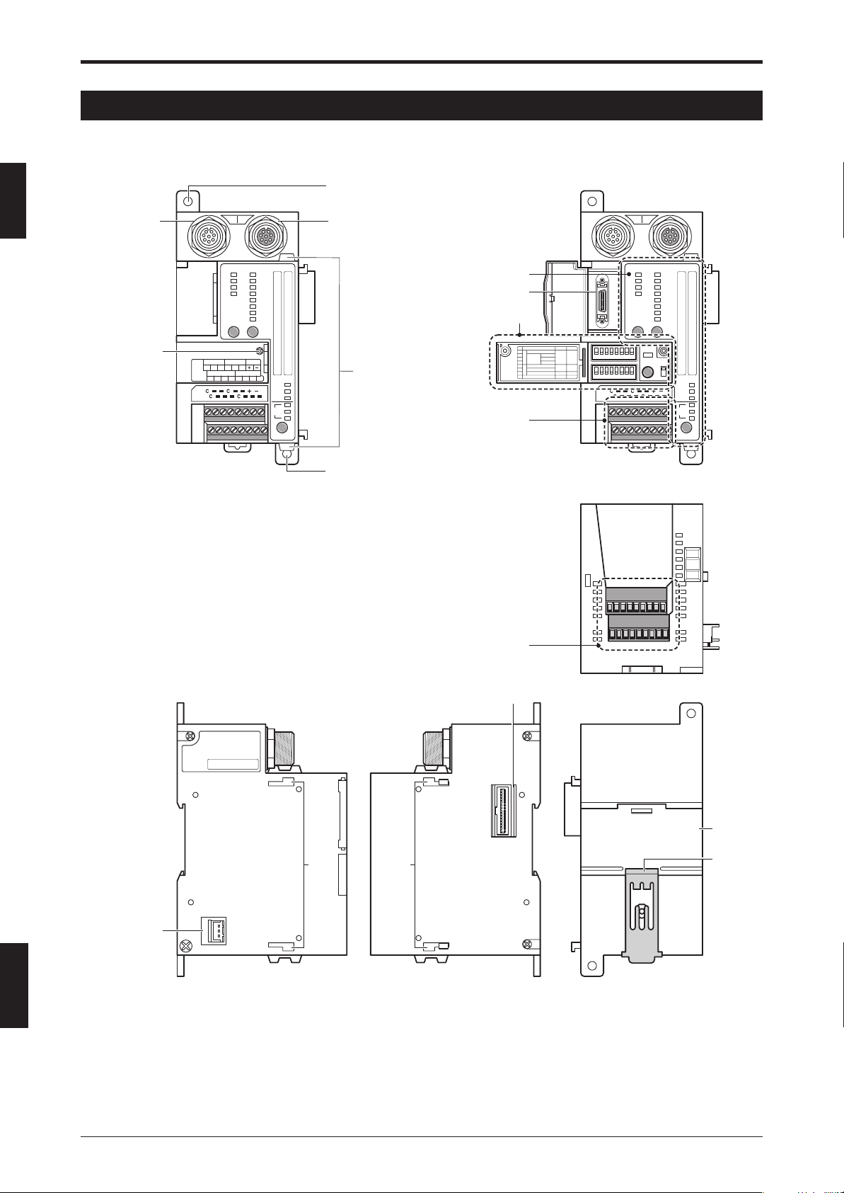
1-1 Part Names
This chapter gives the names of the SL-R12EX parts.
Front view
Hole for mounting screw
(for M4)
12345678
MUTE A
C A1 A2
PMB A
12345678
C A1 A2 A3
T R
UNIT BEAM
4
3
2
1
TEACHING
MUTE B
SET/TEACH
C B1 B2
PMB B
C B1 B2 B3
Blanking blind protection
unit connector (receiver)
CLEAR/
MODE
BLOCKED
STATUS
113-128
16
16
97-112
15
15
81-96
14
14
65-80
13
13
49-64
12
12
33-48
11
11
17-32
10
10
1-16
9
9
8
8
7
7
6
6
5
5
4
4
3
3
LAMP
2
2
PROG.
1
1
RUN
BLANKING
FIXED
FLOATING
B.B.P
1
P.M.
2
BANK
3
Connection hooks
Blanking blind
protection unit
connector
(transmitter)
Function switch
cover screw
Status monitor
SL-R12D status
display connector
Function switches
Input terminal
No. FUNTION UP DOWN
1
Fixed
1beam
2
Enable Disable
2beams
Floating
3
3beams
4
Mute
5
Enable Disable
Programmable
6
Mute Blanking
Inputs
4in 2in
7
MODE SWITCH
Blanking Blind Protect
8
W W/O
Front view
12345678
12345678
T R
UNIT BEAM
4
3
2
1
TEACHING
SET/TEACH
PROG.
RUN
113-128
97-112
81-96
65-80
49-64
33-48
17-32
1-16
CLEAR/
BLOCKED
16
15
14
13
12
11
10
9
8
7
6
5
4
3
2
1
BLANKING
FIXED
FLOATING
B.B.P
P.M.
BANK
MODE
STATUS
16
15
14
13
12
11
10
9
8
7
6
5
4
3
2
1
1
2
3
KEYENCE CORPORATION
SL-R12EX
For use with SL-R11 only.
RATED CURRENT 110 mA
TYPE OF ESPE TYPE 4
MADE IN JAPAN
No.
Hole for mounting screw
(for M4)
Side
SL-U2
mounting
holes
SL-R11
mounting
holes
Input terminal
SL-R11 connector
Bottom
Rear
DIN rail
mating area
Din rail
lock pin
ENGLISH
English
SL-U2 connector
*Covered by tape at
time of shipment.
1-2
Page 11
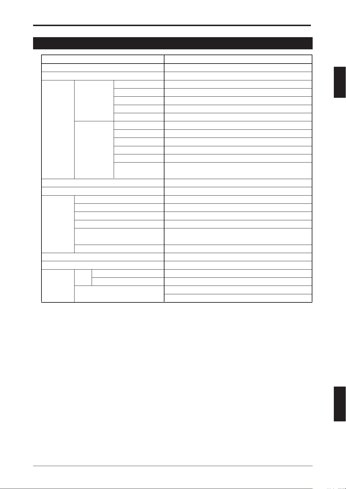
1-2 Specifications
Chapter 1 Specifications
Model
Power supply
Current consumption
Muting
device inputs
Inputs
Bank
switching
inputs
Muting lamp output
Protective structure
Ambient temperature
Storage ambient temperature
Environmental
specifications
Material
Weight
Approved
standards
Relative humidity
Storage ambient humidity
Vibration
Shock
EMC
Safety
EMS
EMI
Max. input voltage
Input rating
Min. ON voltage
Min. OFF current
Common wiring
Max. input voltage
Input rating
Min. ON voltage
Min. OFF current
Common wiring
Permissible timing
lag between 2 inputs
SL-R12EX
Supplied from SL-U2
Max. 110 mA (24 V DC, including SL-R12D)
26.4 V DC
24 V DC, 2.3 mA
19 V
0.5 mA
A1 and A2 are common; B1 and B2 are common.
26.4 V DC
24 V DC, 1.6 mA
19 V
0.5 mA
A1, A2, and A3 are common; B1, B2, and B3 are common.
Max. 200 ms
24 V DC, 15 to 300 mA
IP20 (IEC60529) Must be installed inside a control panel with at least an IP54 rating.
-10 to +55 °C (No frost)
-10 to +60 °C (No frost)
35 to 85% RH (No condensation)
35 to 95% RH
10 to 55 Hz, 0.7 mm (0.03") compound amplitude, 20 sweeps
each in X, Y, and Z directions
100 m/s2 (Approx. 10G) 16 ms pulse, in X, Y, Z directions 1,000 times each axis
Polycarbonate
Approx. 300 g
UL61496-1
FCC Part15B Class A
UL61496-1 (type 4 ESPE)
UL508
1
1-3
ENGLISH
Page 12

Chapter 1 Specifications
1
Model
Detection zone
Beam axis interval
Operating distance
Detection capability
Effective Aperture Angle
Response time
Power supply
Current consumption
Light source
Operation form
Protective structure
Ambient temperature
Storage ambient temperature
Environmental
specifications
Material
Weight
Relative humidity
Storage ambient humidity
Ambient light
Vibration
Shock
Main unit case
Upper case/Lower case
Overlay
SL-C08SB, SL-C16SB
Depends on sensors used.
Beam axis interval: 20 mm (0.79"), Lens diameter: 5.0 mm (0.2")
0.3 to 9 m (0.98 to 29.53 ft.) *Limited by operating distance of sensors used.
ø 25mm (0.98")
Max. ±2.5° (When operating distance is at least 3 m (9.84 ft.))
24 ms (including sensor and SL-R11 response speed)
Supplied from SL-R12EX
Transmitter: Max. 50 mA (24 V DC)
Receiver: Max. 50 mA (24 V DC)
Infrared LED (850 nm)
Turns on when light is received from all light beams (except when
the blanking function is used)
IP65 (IEC60529)
-10 to +55 °C (No frost)
-10 to +60 °C (No frost)
35 to 85% RH (No condensation)
35 to 95% RH
White incandescent lamp: 5,000rx or less Sunlight: 20,000rx or less
10 to 55 Hz, 0.7 mm (0.03") compound amplitude, 20 sweeps each in X, Y, and Z directions
100 m/s2 (Approx. 10G) 16ms pulse, in X, Y, Z directions 1,000 times each axis
Aluminum
Zinc die-cast
Polycarbonate
SL-C08SB: Transmitter approx. 165 g, Receiver approx. 180 g
SL-C16SB: Transmitter approx. 255 g, Receiver approx. 280 g
ENGLISH
English
Model
Power supply
MUTE lamp brightness Min.
Area
Protective structure
Ambient temperature
Environmental
specifications
Material
Weight
Approved
standards
Storage ambient temperature
Relative humidity
Storage ambient humidity
Vibration
Shock
EMC
Safety
EMS
EMI
SL-R12D
Supplied from SL-R12EX
Min. 200 cd/m
2
3 cm
IP65 (IEC60529) Applies to display only when mounted so device
is embedded in a panel.
-10 to +55 °C (No frost)
-10 to +60 °C (No frost)
35 to 85% RH (No condensation)
35 to 95% RH
10 to 55 Hz, 0.7 mm (0.03") compound amplitude, 20 sweeps
each in X, Y, and Z directions
100 m/s2 (Approx. 10G) 16ms pulse, in X, Y, Z directions 1,000 times each axis
Polycarbonate
Approx. 60 g (excluding cables)
UL61496-1
FCC Part15B Class A
UL61496-1
UL508
2
1-4
Page 13
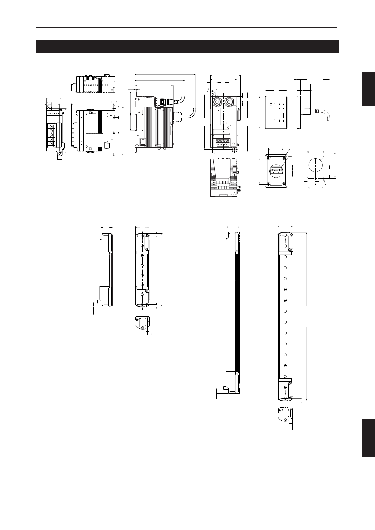
1-3 External Dimensions Diagram
Chapter 1 Specifications
SL-U2
11 (0.43")
2-ø4.2
35 (1.38")
24
(0.94")
(0.43")
11
100
(3.94")
(96.6 (3.8"))
SL-C08SB
(0.14")
26.4
(1.04")
SL-R12EX
3.5
3.5
25.8
(1.02")
35.9 49.8
35.9
(1.41")
111
(4.37")
85.5
(112)
(135)
2-ø4.2
(4.88")
124
15.4
(0.61")
68 (2.68")
60 (2.36")
27
(1.06")
11 (0.43")
49 (1.93")
12.5 (0.49")
135
(5.31")
SL-R12D
72
(2.83")
Bottom
58
(2.28")
48
(1.89")
34
(1.34")
(0.3")
(65 (2.56"))
7.5
21.7
(0.85")
Panel cut dimensions
4-M3
depth 5
ø29.2
(1.15")
9.6 (0.38")
5.6 (0.22")
17
(0.67)
(1.34")
Panel
thickness
1 to 5 mm
(0.04 to 0.2")
34
ø30
(1.18")
29
(1.14")
4-ø3.4
+1
0
58
(2.28")
1
SL-C16SB
28
(1.1")
5.5 (0.22")5.5 (0.22")
26.4
(1.04")
28
(1.1")
5.5 (0.22")5.5 (0.22")
10.8 (0.43")
151 (5.94")
311 (1.02 ft.)
4.5 (0.81")
10.8 (0.43")
ENGLISH
4.5 (0.18")
1-5
Page 14
Chapter 1 Specifications
1-4 Power Supply Precautions
1
1-4-1
The power supply units that can be used as the power supply for SL-C Series, SL-R11 and SL-R12EX must
completely satisfy the following requirements in order to satisfy the requirements of UL61496-1 for the SL-C
Series, SL-R11, and SL-R12EX.
(a) Rated output voltage is 24V DC ±10%.
(b) The power supply to be used shall be a dedicated power supply for the SL-C Series, SL-R11 and/or SL-
(c) The power supply output must satisfy the requirements for a Class 2 Circuit or Limited Voltage/Current
(d) The power supply must comply with the laws, regulations, and standards covering electrical safety,
(e) The output hold time is 20 ms min.
Power Units that Can Be Used as Power Supplies for SL-C Series and SL-R11/SL-R12EX
R12EX and shall not be used to supply power to other devices.
Circuit as prescribed by UL508. (This requirement applies only when the SL-C Series, SL-R11 and/or SLR12EX is to be used in North America.)
electromagnetic compatibility (EMC), etc., for the country or region in which the SL-C Series, SL-R11 and/
or SL-R12EX will be used.
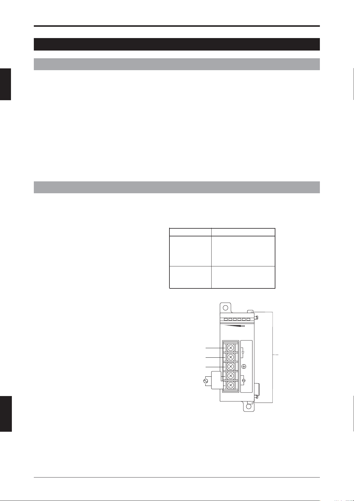
1-4-2 Recommended Dedicated Power Supply Unit
The SL-U2 is offered as the SL-C Series, SL-R11 and SL-R12EX dedicated power supply. The SL-U2 is a
power supply that completely satisfies the above requirements.
<Approved standards>
Standard No.
EN60950
Safety EN50178
standard UL60950 (R/C)
UL508 (Listing)
EN55011 Class A
EMC standard EN61000-6-2
FCC Part 15B Class A
ENGLISH
English
SL-U2
SL-U2
OC
+
24V DC
PE (GND)*
240 V AC
(*) The PE terminal is a protective conductor terminal that must be connected to a protective earthing
conductor in the building.
100 to
–
100-240V AC
CAUTION
ONLY
+
Connection hooks
-
L
N
1-6
Page 15
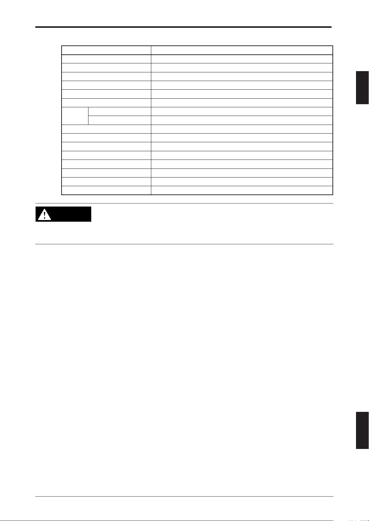
<Specification>
Chapter 1 Specifications
Model
System
Input power supply voltage
Overvoltage category
Output voltage
Ripple/noise
Output capacity
Environment
Pollution degree
Withstand voltage
Vibration resistance
Shock resistance
Insulation resistance
Power consumption 135VA
Supply voltage interruption 10 ms or less
Weight (excluding dedicated brackets)
WARNING
Ambient temperature
Relative humidity
For the power supply used for the SL-C Series, SL-R11 and SL-R12EX, always
use a power supply that can fully satisfy the above requirements or use recommended SL-U2 power supply. Otherwise, the UL61496-1 requirements may not be
satisfied and the SL-C Series, SL-R11 and SL-R12EX may not be recognized as a
safety component.
Switching type
100 V AC to 240 V AC ±10 % (50/60 Hz)
2
24 V DC ±10 %, Class 2
240 mVp-p or less
1.8 A
-10 °C to +55 °C (non-freezing)
35 % to 85 % RH (non-condensing)
2
1,500 V AC, 1 min. (between all external terminals and case)
10 to 55 Hz, 0.7 mm (0.03") compound amplitude, 20 sweeps each in X, Y, and Z directions
100 m/s2, 1,000 iterations each in X, Y, and Z directions
At least 50 MW (500 V DC mega, between all external terminals and case)
Approx. 240 g
SL-U2
1
1-7
ENGLISH
Page 16

1
Chapter 1 Specifications
MEMO
ENGLISH
English
1-8
Page 17
Chapter 2 Functions
2 Functions
2-1 Foreword
This section describes the functions that are provided by the SL-R12EX. These functions allow you to
configure various settings related to the detection performance of the SL-R11 and SL-C Series devices that
are connected to the SL-R12EX and can be set for individual SL-C Series beam axes. For this reason,
references throughout this text to “detection capability” and “beam axes” should be understood to refer to the
detection capability and beam axes of the SL-C Series.
2-2 Floating blanking function
When this function is carried out, the SL-C series cannot keep the original
WARNING
detection capability. The detection capability of the SL-C**F Series varies among
ø14 mm (0.55"), ø24 mm (0.94"), ø34 mm (1.33"), and ø44 mm (1.73") according
to the exact settings used. The detection capability of the SL-C**H Series varies
among ø25 mm (0.98"), ø45 mm (1.77"), ø65 mm (2.56"), and ø85 mm (3.35")
according to the exact settings used. Therefore you must accurately calculate the
new safety distance and install the SLC Series at the minimum safety distance
separately from the hazardous zone or hazards. When installing the SL-C Series
onto/into a machine, always follow the instructions in the SL-C Series Instruction
Manual. Failure to follow this warning may result in significant harm to machine
operators, including serious injury or death.
2
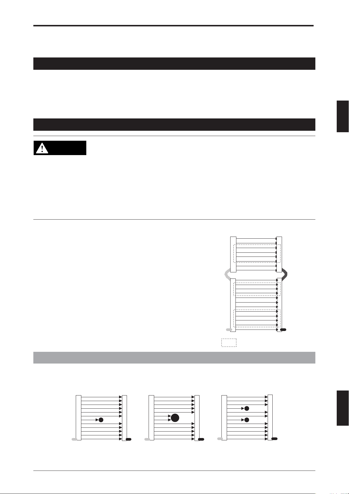
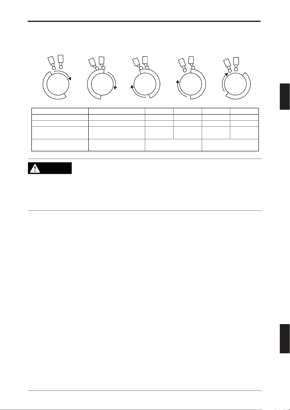
Normally, the FSD turns OFF-state when an obstacle blocks even a
single SL-C Series beam axis. When this function is enabled, the FSD
keeps ON-state in the event that only a preset number (between 1 and
3) of beam axes are blocked. Only when the number of beam axes
blocked by the objects exceeds that preset number, the FSD turns
OFF-state.
In order to carry out this function, the SL-C Series need not be a single
transmitter/receiver pair. This function can be set for all beam axes on
all SL-C Series units connected in series. (See the right diagram.)
See “4-2 Floating blanking function” (➮4-2) for more information about
how to set or configure this function.
This function can be configured in one of three ways, as indicated
below.
<Example configuration>
: Zone where floating blanking
function is active
Connected
in series
2-2-1 Floating blanking for 1 beam axis
The FSD keeps ON-state when only 1 beam axis is blocked, and turns OFF-state when 2 or more beam
axes are blocked. Note that for the SL-C**F Series the detection capability is ø24 mm (0.94"), and for the SLC**H Series the detection capability is ø45 mm (1.77").
ENGLISH
●: Object blocking beam axis
FSD keeps ON-state
●: Object blocking beam axis
FSD is OFF-state
●: Object blocking beam axis
FSD is OFF-state
2-1
Page 18
2
Chapter 2 Functions
2-2-2 Floating blanking for 2 beam axes
The FSD keeps ON-state when 1 or 2 beam axes are blocked, and turns OFF-state when 3 or more beam
axes are blocked. Note that for the SL-C**F Series the detection capability is ø34 mm (1.33"), and for the SLC**H Series the detection capability is ø65 mm (2.56").
2-2-3 Floating blanking for 3 beam axes
The FSD keeps ON-state when 1, 2, or 3 beam axes are blocked, and turns OFF-state when 4 or more
beam axes are blocked. Note that for the SL-C**F Series the detection capability is ø44 mm (1.73"), and for
the SL-C**H Series the detection capability is ø85 mm (3.35").
2-3 Fixed blanking function
ENGLISH
English
WARNING
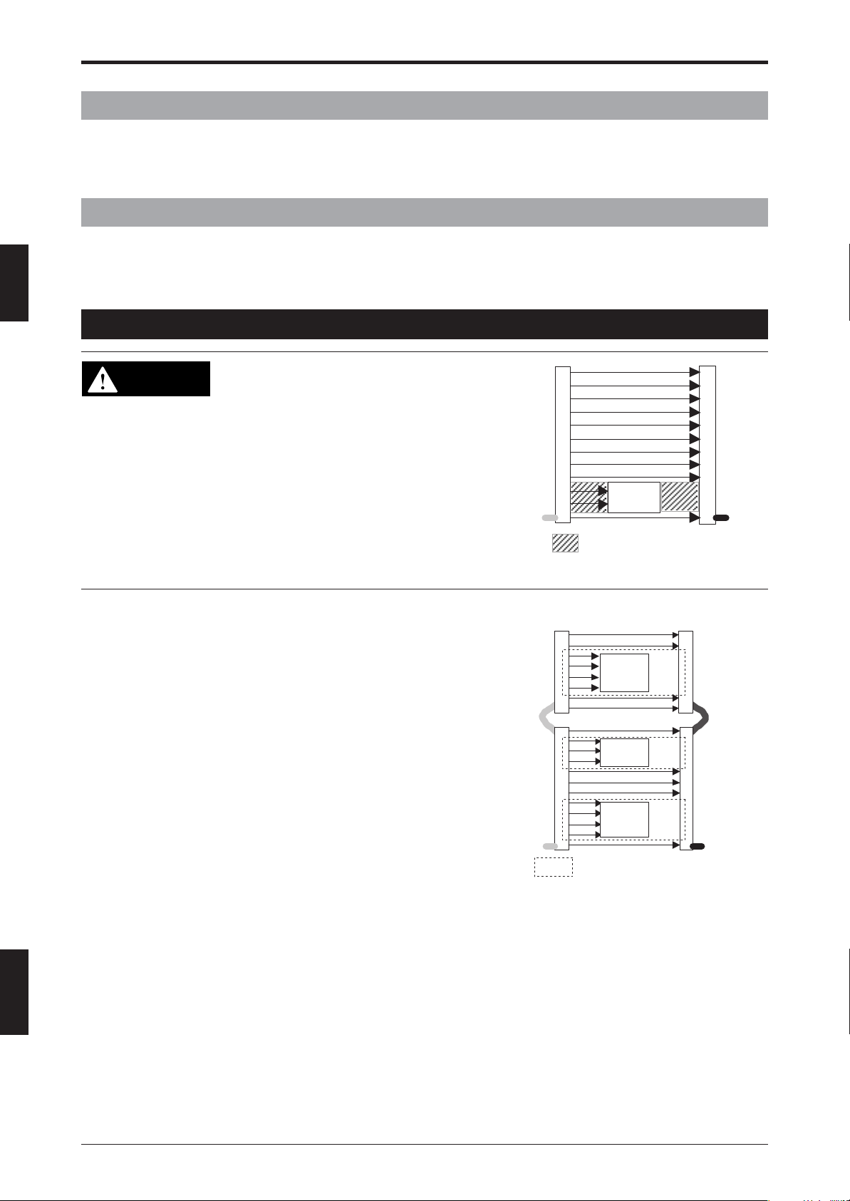
Normally, the FSD keeps the ON-state only when all beam axes are
clear of any obstruction (that is, when there are no obstacles present
in the detection zone). The Fixed blanking function is enabled only for
the beam axes in the zone initially specified by the user and allows the
FSD to keep ON-state when an obstacle blocks the beam axes in that
zone.
For example, if an obstacle blocks the beam axes of the SL-C Series,
the FSD turns OFF-state (see the right diagram.) In contrast, if the
light curtain is configured to enable fixed blanking, the FSD keeps ONstate when an obstacle blocks these pre-set beams. It allows the
target machine to continue the normal operation. Conversely, if the
obstacle is removed from the detection zone while this function is
carried out, the FSD turns OFF-state and it causes the machine stop.
Note that enabling this function may create hazardous zones, allowing
human approach against which the SL-C Series provides no protection. It is required to install additional safety protective equipment like
a cover designed to prevent human approach.
In order to carry out this function, the SL-C Series need not be a
single transmitter/receiver pair The function can be configured to be
operational for all beam axes on all SL-C Series units connected in
series. (See the right diagram.)
See “4-3 Fixed blanking function” (➮4-3) for more information about
how to set or configure this function.
When this function is carried out, it may
create a hazardous zone allowing human
approach between the obstacle and the SL-C
Series against which the SL-C Series provides no protection. (See the right diagram.)
Be sure to install additional safety protective
equipment, such as a safe guard, for this
zone. When installing the SL-C Series into/
onto a machine, always follow the instructions
in the SL-C Series Instruction Manual. Failure
to follow this warning may result in significant
harm to machine operators, including serious
injury or death.
Obstacle
: Hazardous zone allowing
human approach
<Example configuration>
Obstacle
Obstacle
Obstacle
: Zone where fixed blanking
function is active
Connected
in series
2-2
Page 19
2-4 Blanking blind protection function
Chapter 2 Functions
WARNING
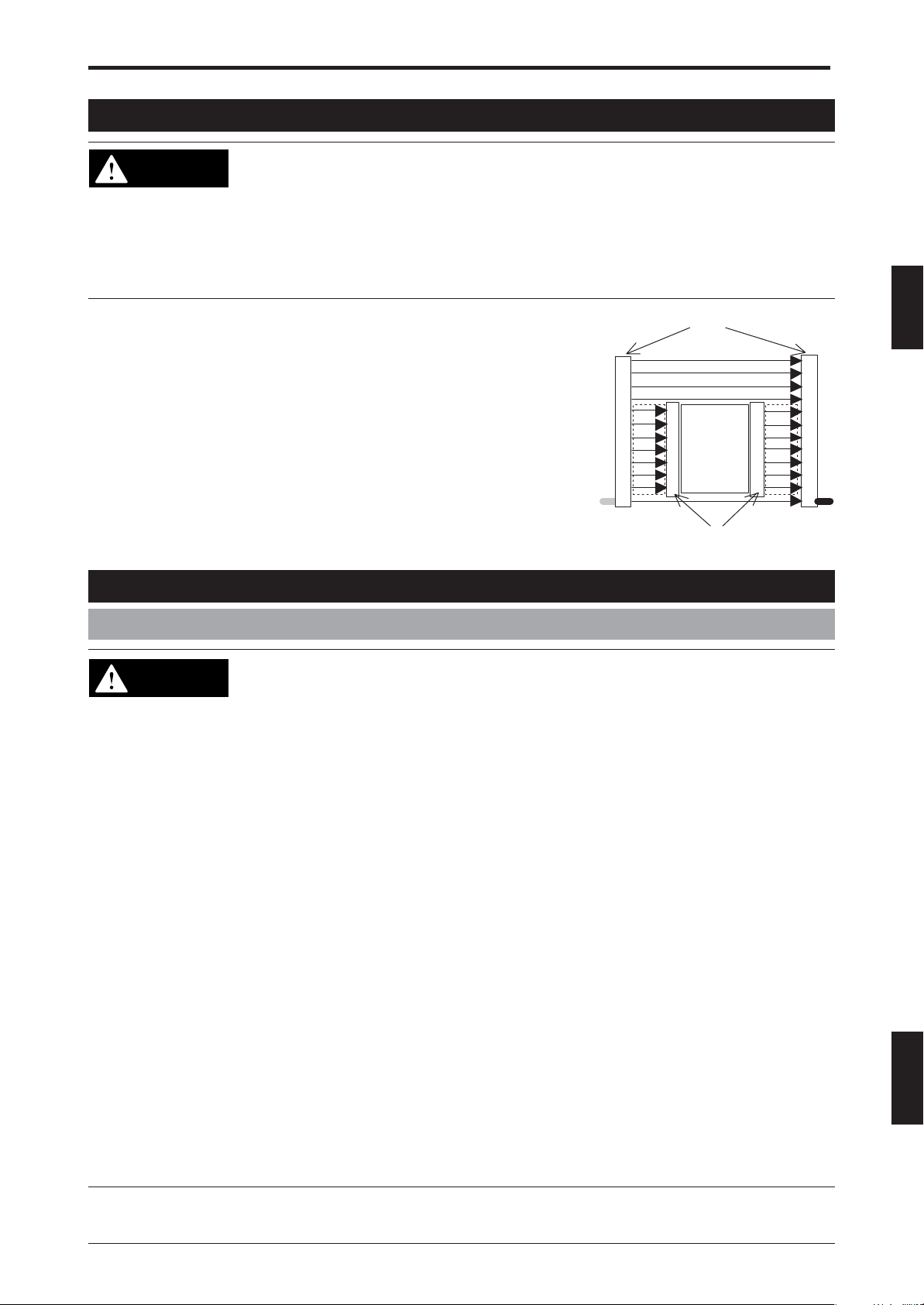
This function is an advanced improvement of the fixed blanking function.
It can be used to eliminate the hazardous zone allowing human approach
that arises when the conventional fixed blanking function is enabled.
(Subject to the above warning.)
A blanking blind protection unit (SL-C08SB or SL-C16SB) is required in
order to enable this function. As shown in the right diagram, the blanking
blind protection unit is placed on either side of the obstacle so that the SL-C
Series transmitter faces the blanking blind protection unit's receiver, and the
blanking blind protection unit's transmitter faces the SL-C Series receiver,
with all beam axes aligned. This configuration may eliminate the hazardous zones allowing human approach that are created by the obstacle.
Be sure to read “4-4 Blanking blind protection function” (➮4-4) carefully
for more information about how to set and install this unit before use.
Enabling the blanking blind protection function does not necessarily remove all
hazardous zones allowing human approach. Depending on the target machine,
installation of the blanking blind protection unit may result in the creation of one or
more hazardous zones allowing human approach. Be sure to read “4-4 Blanking
blind protection function” (➮4-4) in this manual before installing or using this unit.
When installing the SL-C Series into/onto a machine, always follow the instructions
in the SL-C Series Instruction Manual. Failure to follow this warning may result in
significant harm to machine operators, including serious injury or death.
2-5 Muting function
SL-C Series
Obstacle
Blanking blind protection unit
2
2-5-1 Muting function
• The muting function deactivates the light curtain's safety functions while the light
DANGER
curtain detects the input signal from two or more muting devices (sensors,
switches, etc.). The muting devices (sensors, switches, etc.) that are used to carry
out the muting function as well as the method to install them must satisfy all
conditions described in this instruction manual as well as the applicable requirements imposed by all laws, regulations, standards, and ordinances in effect in the
country and region where the SL-R12EX is to be used. Failure to follow this
warning results in significant harm to machine operators, including serious injury
or death.
• The following conditions must be considered before installing muting devices
(sensors, switches, etc.) to carry out the muting function.
1. The muting function of the light curtain is only permitted during the nonhazard-
ous portion of the machine cycle.
2. Muting devices must not get active and the light curtain (SL-C Series) must
not go to the muting state even if a person inadvertently approaches the light
curtain's detection zone.
These are minimum requirements. Always follow the regulations in effect in the
country and region where the SL-R12EX is used.
In addition, you must take note of the following information if you carry out the
muting function.
• Muting of the light curtain shall be accomplished in such a manner that no
single component failure shall prevent the normal stop command and shall
prevent subsequent machine cycles until the failure is corrected. (ANSI B11.19)
• Setting the muting function and muting device configuration must be restricted
to an extremely limited number of the responsible personnel.
• Any personnel other than the responsible personnel must not easily change
the position at which the muting devices are installed. When the muting devices are moved, the procedure must require the use of specialized tools and
must be performed under the responsibility of the responsible personnel.
ENGLISH
2-3
Page 20
Chapter 2 Functions
The muting function supported by the SL-C Series can be classified into two types.
I)A muting function where the safety functions of all beam axes, including those on SL-C Series units
connected in series, are disabled when the signals from the muting devices are ON (active).
II)A muting function (called as the programmable muting function) where the safety functions of pre-defined
beam axes are disabled when the signals from the muting devices are ON (active).
For all beam axes for which either of the functions described in I and II is enabled, the FSD keeps ON-state
even when those beam axes are blocked by the detection capability.
Both of the functions described in I and II above support either 2 or 4 input signals from the muting devices,
comprising the 4 types of muting function described below.
2
Examples of 2-input muting
See the pages starting with “2-5-2 Two-input muting” (➮2-8) for detailed time charts of this function.
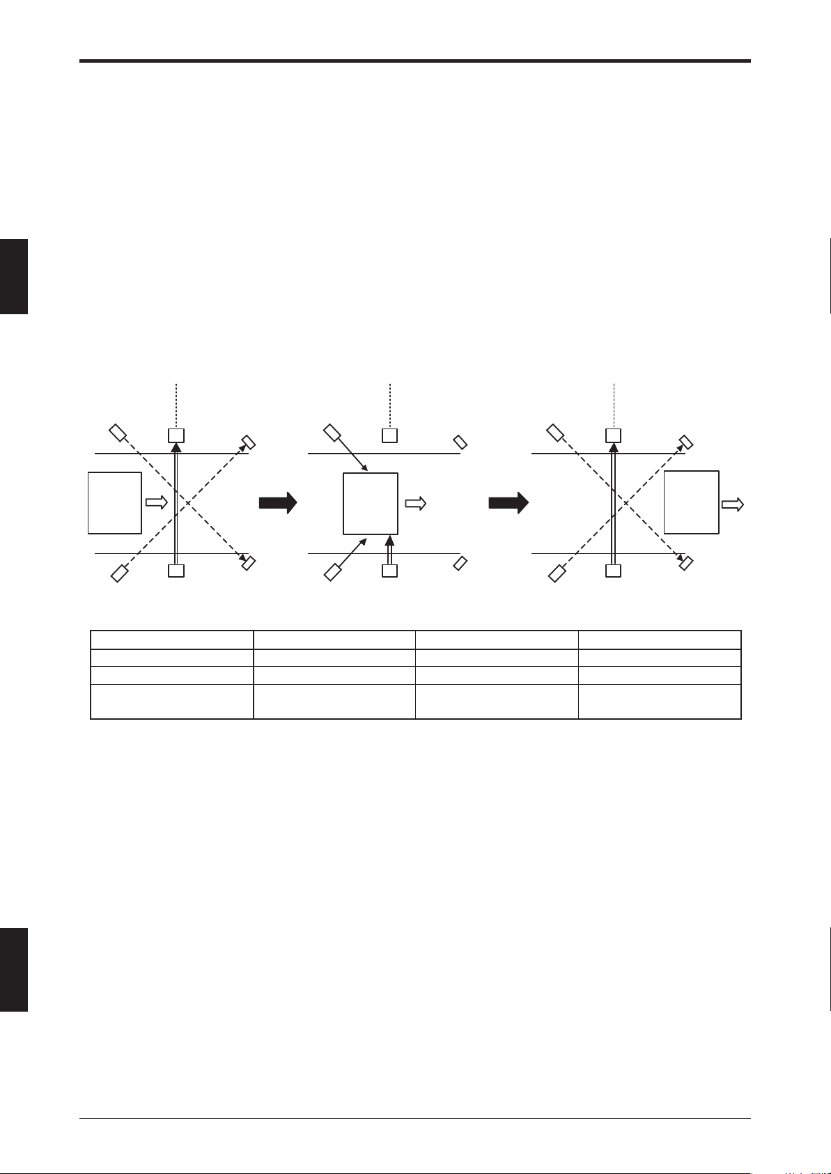
1. Using 2 retro-reflective photoelectric sensors (Keyence model PZ-M61, etc.) as muting devices
(1) (2) (3)
Safe zone Hazardous zone
Sensor A1
Workpiece
Sensor A2
SL-C Series
Sensor A1 OFF ON OFF
Sensor A2 OFF ON OFF
SL-C Series state
Safe zone Hazardous zone
Reflector
Reflector
Sensor A1 Sensor A1
Workpiece
Sensor A2
SL-C Series
Reflector
Reflector
(1) (2) (3)
Safety functions enabled Safety functions disabled Safety functions enabled
(Normal operation) (Muting function enabled) (Normal operation)
Safe zone Hazardous zone
Sensor A2
SL-C Series
Reflector
Workpiece
Reflector
ENGLISH
English
* In the example described above, 2 muting devices are installed so that the location where their beam
axes intersect falls within the hazardous zone. This prevents the muting function from being active even if
a person inadvertently passes the point where the beams intersect.
2-4
Page 21
2. Using 2 cam switches as muting devices for a mechanical presses, etc.
(1) (2) (3) (4) (5)
Switch A1
SL-C Series state
Switch A2
Cam
Sensor A1 OFF ON ON OFF OFF
Sensor A2 OFF ON ON ON OFF
Machine state Bottom dead center Rising
A2
A1
(1) (2) (3) (4) (5)
Safety functions enabled Safety functions disabled Safety functions enabled
(Normal operation) (Muting function enabled) (Normal operation)
A1
A2
A2
A1
Top dead Starting to
center fall
Chapter 2 Functions
A2
A1
Falling
2
WARNING
The SL-R12EX has not received the model certification examination in accordance
with Article 44-2 of the Japanese Industrial Safety and Health Law. As a result, the
SL-R12EX cannot be used in Japan as a “Safety Device for Presses and Shearing
machines” as established in Article 42 of that law.
When using the SL-C Series, including SL-R11 and SL-R12EX with mechanical
press equipment in the United States, check the regulations stipulated in
OSHA1910.217 and ANSI B11.1, B11.2, and B11.3, and be sure to follow those
regulations in both the installation and use.
2-5
ENGLISH
Page 22

Chapter 2 Functions
Examples of 4-input muting
See the pages starting with “2-5-3 Four-input muting” (➮2-9) for detailed time charts of this function.
1. Using 4 thrubeam photoelectric sensors (KEYENCE model PZ-M51, etc.) as muting devices
2
(1) (2)
Sensor A1
Workpiece
(3) (4)
Safe zone Hazardous zone
Sensor A2
SL-C Series
Safe zone Hazardous zone
A2
Sensor
Sensor A1
Workpiece
Sensor B1
Sensor B2
Sensor B1
Sensor B2
Sensor
Workpiece
Sensor A1
Sensor
Sensor B2
B 1
Sensor
Safe zone Hazardous zone
A 2
Sensor
A1
SL-C Series
Safe zone Hazardous zone
Sensor A2
Sensor B1
Workpiece
B 2
ENGLISH
English
SL-C Series
(5) (6)
Sensor A1
Safe zone Hazardous zone
Sensor A2
Sensor B1
Sensor B2
Workpiece
SL-C Series
Sensor A2
Sensor A1
SL-C Series
Safe zone Hazardous zone
Sensor B1
Sensor B2
Workpiece
SL-C Series
2-6
Page 23
State (1) (2) (3) (4) (5) (6)
Sensor A1 OFF ON ON ON OFF OFF
Sensor A2 OFF OFF ON ON OFF OFF
Sensor B1 OFF OFF OFF ON ON OFF
Sensor B2 OFF OFF OFF ON ON ON
SL-C Series state
* Muting device location in the above examples
(Normal operation) (Muting function enabled) (Normal operation)
Safety functions enabled Safety functions disabled Safety functions enabled
Chapter 2 Functions
Safe zone Hazardous zone
Sensor A2
Sensor A1
Workpiece
L
See “4-5 Muting function” (➮4-10) for information about how to set or configure these functions.
In order to carry out this function, you must install muting devices (sensors, switches, etc.) and a muting
lamp (SL-R12D is recommended). See “4-5-1 Muting devices” (➮4-10) for information about muting device
requirements and “4-5-2 Muting lamps” (➮4-12) for information about muting lamp requirements.
The information presented up to this point is intended as an example of typical requirements. The satisfaction of these requirements must not be understood as being equivalent to the satisfaction of all regulations
imposed on the muting function (including methods of installation and use) being used by the customer.
Therefore, KEYENCE does not guarantee the validity and/or accuracy for use, installation and orientation
methods of the muting devices that the customers made. Accordingly, customers intending to carry out the
muting function must check the all applicable regulations in effect in the country and region where the SLR12EX is used.
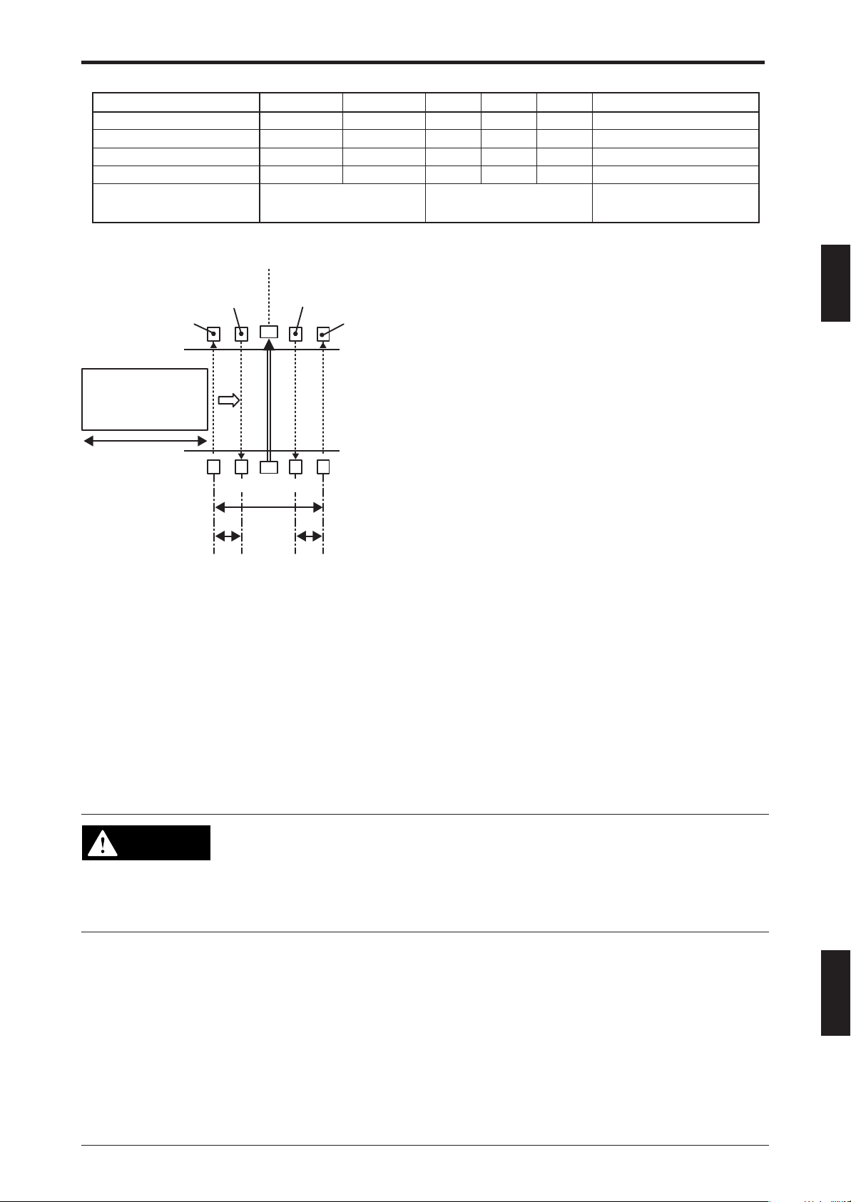
S
SL-C Series
D2 D3
Sensor B1
Sensor B2
D1
As indicated in the diagram to the left, L represents the
workpiece length, while S indicates the speed of the
workpiece as it approaches the light curtain's detection
zone.
When installing the muting devices, the following conditions must be fully satisfied.
D1: The distance between A1 and B2
D2: The distance between A1 and A2
D3: The distance between B1 and B2.
L: The length of the workpiece
S: The speed of the workpiece
(1) D1 < L
(2) D2 < S X 3 (seconds)
(3) D3 < S X 3 (seconds)
2
WARNING
Customers who carry out the muting function bear sole responsibility for complying
with the requirements imposed on that function. KEYENCE makes no guarantee
regarding damage arising from installation, orientation, usage, or maintenance not
in accordance with what is described in this instruction manual, or from the failure
to follow all applicable regulations in effect in the country and region in which the
SL-R12EX is used.
ENGLISH
2-7
Page 24

2
Chapter 2 Functions
2-5-2 Two-input muting
The light curtain (SL-C Series) goes to the muting state when it detects the input signals from 2 muting
devices, and the FSD keeps ON-state no matter which beam axes of SL-C Series are blocked.
The following time chart shows the muting function performance when two sensors are used as the muting
devices.
ON
Sensor A1
Sensor A2
Muting function
Beam reception
FSD
OFF
ON
OFF
ON
OFF
Clear
Blocked
ON
OFF
24 ms
Less than 3 sec.
20 ms
150 ms
5 ms
(1) (2) (3)
Time chart explanation
(1) The muting function does not get active when both sensors A1 and A2 are OFF, or when only one of them
is ON. In other words, the light curtain (SL-C Series) keeps normal operation. (The muting function is
OFF.)
(2) The muting function gets active once both sensors A1 and A2 turn ON, and then, the muting lamp turns
ON.
(3) Once either sensor A1 or A2 turns OFF, the muting function is to be inactive. Therefore, the light curtain’s
(SL-C Series) muting state is canceled. The muting lamp turns OFF, and the light curtain (SL-C Series)
returns to normal operation.
Important: * The SL-C Series muting function is designed so that it cannot be active while FSD is OFF-
state. As a result, the SL-C Series does not go to the muting state when any beam axes are
being blocked or when the restart interlock is enabled, even if the signals from the 2 muting
devices turn ON.
* When the SL-R11 receives an E-STOP input signal, the FSD always turns to OFF-state and
the light curtain (SL-C Series) automatically goes to the restart interlock state, even if it has
been in the muting state. When the E-STOP input signal is canceled and the restart input
turns ON, the light curtain (SL-C Series) returns to normal operation, rather than resuming
the set muting state. As a result, in order to return the light curtain (SL-C Series) to the
muting state again, you must temporarily cancel the input signals from the muting devices
that have been activated and resend the input signals from them to the SL-R12EX.
* The SL-C Series cannot go to the muting state after 1 muting device turns OFF, even if both
devices then turn back ON again. Both muting devices must turn OFF to get the muting
function active again.
ENGLISH
English
2-8
Page 25

Chapter 2 Functions
2-5-3 Four-input muting
The light curtain (SL-C Series) goes to the muting state when it received input signals from 4 muting devices,
and the FSD keeps ON-state no matter which beam axes of the SL-C Series is blocked.
The following time chart shows the muting function performance when four sensors are used as muting
devices.
Forward direction
Sensor A1
Sensor A2
Sensor B1
Sensor B2
Muting function
Beam reception
FSD
ON
OFF
ON
OFF
ON
OFF
ON
OFF
ON
OFF
Clear
Blocked
ON
OFF
24 ms
Less than 3 sec.
Less than 3 sec.
20 ms
150 ms
(1) (2) (3)
5 ms
2
Time chart explanation
(1) The muting function does not get active when the signals from the muting devices are all OFF. In other
words, the light curtain (SL-C Series) keeps normal operation. (The muting function is OFF)
(2) The muting function gets active once the signal from sensor A1 turns ON at first and the signal from
sensor A2 turns ON sequentially. At this time, the muting lamp turns ON. Further, the signal from sensor
B1 turns ON, and finally, the signal from sensor B2 turns ON. As long as the light curtain (SL-C Series)
receives the signals from the muting devices in this sequence, it keeps muting function.
(3) If the signal from sensor A1 turns OFF, A2 turns OFF and then B1 also turns OFF sequentially after the
signals from all the sensors turn ON, the muting function cannot keep active. Therefore, the light curtain's
(SL-C Series) muting state is canceled. The muting lamp turns OFF, and the light curtain (SL-C Series)
returns to normal operation.
ENGLISH
2-9
Page 26

Chapter 2 Functions
The following time chart shows muting function performance when it gets active in the reverse sequence
from above. This time chart also assumes sensor is used as muting devices.
Reverse direction
Sensor A1
ON
OFF
2
Sensor A2
Sensor B1
Sensor B2
Muting function
Beam reception
FSD
Time chart explanation
(1) The muting function does not get active when the signals from the muting devices are all OFF. In other
words, the light curtain (SL-C Series) keeps normal operation. (The muting function is OFF)
(2) The muting function gets active once the signal from sensor B2 turns ON at first and the signal from
sensor B1 turns ON sequentially. At this time, the muting lamp turns ON. Further, the signal from sensor
A2 turns ON, and finally, the signal from sensor A1 turns ON. As long as the light curtain (SL-C Series)
receives the signals from the muting devices in this sequence, it keeps the muting function.
(3) If the signal from sensor B2 turns OFF, B1 turns OFF and then A2 also turns OFF sequentially after the
signals from all the sensors turn ON. The muting function cannot keep active. Therefore, the light curtain's
(SL-C Series) muting state is canceled. The muting lamp turns OFF, and the light curtain (SL-C Series)
returns to normal operation.
ON
OFF
ON
OFF
ON
OFF
ON
OFF
Clear
Blocked
ON
OFF
24 ms
Less than 3 sec.
Less than 3 sec.
20 ms
150 ms
(1) (2) (3)
5 ms
ENGLISH
English
2-10
Page 27

Chapter 2 Functions
Important: * In the event that the signals from the muting devices turn ON or OFF in a different sequence
from what is indicated in the above 2 time charts (for either the forward and reverse directions) – for example, signal input from sensor A1 is followed by signal input from sensor B1,
etc. – the light curtain (SL-C Series) goes to the lockout condition, and the FSD turns OFFstate.
* The SL-C Series muting function is designed so that it cannot be active while FSD is in the
OFF-state. As a result, the SL-C Series does not go to the muting state when any beam
axes are being blocked or when the restart interlock is enabled, even if the signals from the 4
muting devices turn ON in the correct sequence indicated above.
* When the SL-R11 receives an E-STOP input signal, the FSD always turns OFF-state and
the light curtain (SL-C Series) automatically goes to the restart interlock state, even if it has
been in the muting state. When the E-STOP input signals are canceled and the restart input
turns ON, the light curtain (SL-C Series) returns to normal operation, rather than resuming
the set muting state. As a result, in order to return the light curtain (SL-C Series) to the
muting state again, you must temporarily cancel the input signals from the muting devices
that have been activated and resend the input signals from them to the SL-R12EX.
* In the event that a change of the signal from one of the muting devices (ON or OFF) is not
followed by a change of the signal from the next muting device in less than 5 minutes, the
light curtain (SL-C Series) goes to the lockout condition, and the FSD turns OFF-state. (See
the below time chart for reference.)
2
Example
Sensor A1
Sensor A2
Sensor B1
Sensor B2
Muting function
Beam reception
FSD
ON
OFF
ON
OFF
ON
OFF
ON
OFF
ON
OFF
Clear
Blocked
ON
OFF
Lockout
More than 5 min.
2-11
ENGLISH
Page 28

2
Chapter 2 Functions
2-5-4 Two-input programmable muting function
Only the preset beam axes are muted if the memory bank switching input turns ON while the signals from
muting devices are ON. The FSD keeps ON-state even if the muted beam axes are blocked. On the other
hand, the FSD turns to the OFF-state if beam axes other than the muted ones are blocked, since those
beam axes keep normal operation.
The information about the preset beam axes for muting is stored in 3 memory banks, and you can switch
among those banks using inputs from an external source. Although the following time chart shows only 1
bank switching input signal in order for the customer’s easy understanding of this function, actually 2 (double) signals are required for 1 bank switching input (Duplication). See “4-5-5 Bank switching input devices”
(➮4-17) for more information.
The following time chart shows programmable muting bank function performance when 2 sensors are used
as muting devices.
ON
Sensor A1
Sensor A2
Bank switching inputs
OFF
ON
OFF
ON
OFF
Less than 3 sec.
ENGLISH
English
Muting function
Muting lamp
Beam reception
FSD
Time chart explanation
(1) The muting function does not get active when both sensors A1 and A2 are OFF, or when only one of them
is ON. In other words, the light curtain (SL-C Series) keeps normal operation. (The muting function is
OFF.)
(2) The muting lamp turns ON when both sensors A1 and A2 turn ON. At this time, if any one of the 3 bank
switching inputs has already been ON, the preset beam axes in the bank go to the muting state. Even if
muted beam axes are blocked, the FSD keeps ON-state.
If 2 or more bank switching inputs have already been ON prior to the inputs from 2 muting devices, then
all preset beam axes in these banks go to the muting state.
(3) If all of the bank switching inputs turn OFF when both sensors A1 and A2 keep ON, the muting function is
canceled, and the light curtain (SL-C Series) returns to normal operation. At this time, the muting lamp
does not turn OFF. (The muting lamp turns OFF when at least either sensors A1 or A2 turns OFF.)
ON
OFF
ON
OFF
Clear
Blocked
ON
OFF
24 ms
5 ms
20 ms
150 ms
(1) (2) (3)
20 ms
2-12
Page 29

Chapter 2 Functions
Important:*The SL-C Series muting function is designed so that it cannot be active while FSD is in the
OFF-state. As a result, the SL-C Series does not go to the muting state when any beam axes
are being blocked or when the restart interlock is enabled, even if the signals from the 2
muting devices turn ON.
* Bank switching input requires 2 (double) channels of signal input. As a result, if one of the
channels is ON while the other is OFF for 200 ms or more, the light curtain (SL-C Series)
goes to the lockout condition.
* At least 1 of the bank switching inputs must be ON prior to the signal input from the second
muting device (in the example above, the input signal from sensor A2). Therefore, in order to
switch among the 3 banks, you must turn the bank switching input ON when the SL-R12EX
detects no signals from the muting devices, or when it only detects the signal from the first
muting device (in the example above, the input signal from sensor A1).
* If additional bank switching input is made while a muted beam axis is blocked, the FSD turns
to OFF- state.
* When the SL-R11 receives an E-STOP input signal, the FSD always turns OFF-state and
the light curtain (SL-C Series) automatically goes to the restart interlock state, even if it has
been in the muting state. When the E-STOP input signal is canceled and the restart input
turns ON, the light curtain (SL-C Series) returns to normal operation, rather than resuming
the set muting state. As a result, in order to return the light curtain (SL-C Series) to the
muting state again, you must temporarily cancel the input signals from the muting devices
that have been activated and resend the input signals from them to the SL-R12EX.
* If there is no bank switching input to the SL-R12EX while the signals from the muting devices
are ON, the programmable muting bank function does not get active and the light curtain
(SL-C Series) keeps normal operation. However, the muting lamp turns ON if there is signal
input from the muting devices.
* The SL-C Series cannot go to the muting state after 1 muting device turns OFF, even if both
devices then turn back ON again. Both muting devices must turn OFF to get muting function
active again.
2
2-13
ENGLISH
Page 30

2
Chapter 2 Functions
2-5-5 Four-input programmable muting function
Only preset beam axes can be in a muting state if the memory bank switching input turns ON while the
signals from the muting devices are ON. The FSD keeps ON-state even if the muted beam axes are blocked.
On the other hand, the FSD turns OFF-state if beam axes other than the muted ones are blocked, since
those beam axes keep normal operation.
The information about the preset beam axes for muting is stored in 3 memory banks, and you can switch
among these banks using inputs from the external sources. Although the following time chart shows only 1
bank switching input signal in order for customer’s easy understanding for this function, actually 2 (double)
signals are required for 1 bank switching input (Duplication). See “4-5-5 Bank switching input devices” (➮4-
17) for more information.
The following time chart shows programmable muting bank function performance when 4 sensors are used
as muting devices.
Forward direction
ON
Sensor A1
Sensor A2
Sensor B1
OFF
ON
OFF
ON
OFF
Less than 3 sec.
ENGLISH
English
Sensor B2
Bank switching inputs
Muting function
Muting lamp
Beam reception
FSD
Time chart explanation
(1) The muting function does not get active when both sensors A1 and A2 are OFF, or when only one of them
is ON. In other words, the light curtain (SL-C Series) keeps normal operation. (The muting function is
OFF.)
(2) The muting function is enabled once the signal from sensor A1 turns ON at first and the signal from
sensor A2 turns ON sequentially. At this time, the muting lamp turns ON. If any one of the 3 bank switching inputs has already been ON, the preset beam axes in the bank go to the muting state. Even if muted
beam axes are blocked, the FSD keeps ON-state.
If 2 or more bank switching inputs have already been ON prior to the inputs from 2 muting devices, the all
preset beam axes in these banks go to the muting state.
(3) The signal from sensor B1 turns ON, and then, the signal from sensor B2 should turn ON. As long as the
SL-R12EX detects the signals from the muting devices in this sequence, it keeps the muting function as
in (2) above.
ON
OFF
ON
OFF
ON
OFF
ON
OFF
Clear
Blocked
ON
OFF
24 ms
Less than 3 sec.
20 ms
150 ms
(1) (2) (3) (4) (5)
5 ms
20 ms
2-14
Page 31

Chapter 2 Functions
(4) Even if the signal from sensor A1 turns OFF and then A2 also turns OFF sequentially after the signals
from all the sensors turn ON, it keeps the muting function as in (2) above as long as the SL-R12EX
detects the signals from the muting devices in this sequence and the signals from sensors B1 and B2 still
keep ON. Even if muted beam axes are blocked, the FSD keeps ON-state.
(5) When the signal from sensor B1 turns OFF, the muting function is canceled, and the light curtain (SL-C
Series) returns to normal operation. At this time, the muting lamp turns OFF. Alternatively, if all bank
switching inputs turn OFF, even as the signal from sensor B1 keeps ON, the muting function is canceled,
and the light curtain (SL-C Series) returns to normal operation. At this time, the muting lamp does not turn
OFF. (The muting lamp turns OFF when sensor B1 turns OFF in correct sequence.)
Reverse direction
ON
Sensor A1
Sensor A2
Sensor B1
OFF
ON
OFF
Less than 3 sec.
ON
OFF
2
Sensor B2
Bank switching input
Muting function
Muting lamp
Beam reception
FSD
ON
OFF
ON
OFF
ON
OFF
ON
OFF
Clear
Blocked
ON
OFF
24 ms
Less than 3 sec.
5 ms
20 ms
150 ms
(1) (2) (3) (4) (5)
20 ms
Time chart explanation
(1) The muting function does not get active when both sensors B2 and B1 are OFF, or when only one of them
is ON. In other words, the light curtain (SL-C Series) keeps normal operation. (The muting function is OFF.)
(2) The muting function is enabled once the signal from sensor B2 turns ON at first and the signal from
sensor B1 turns ON sequentially. At this time, the muting lamp turns ON. If any one of the 3 bank switching inputs has already been ON, the preset beam axes in the bank go to the muting state. Even if muted
beam axes are blocked, the FSD keeps ON-state.
If 2 or more bank switching inputs have already been ON prior to the inputs from 2 muting devices, then
all preset beam axes in these banks go to the muting state.
(3) The signal from sensor A2 turns ON, and then, the signal from sensor A1 turns ON. As long as the SL-
R12EX detects the signals from the muting devices in this sequence, it keeps the muting function as in (2)
above.
(4) Even if the signal from sensor B2 turns OFF and then B1 also turns OFF sequentially after the signals
from all the sensors turn ON, it keeps the muting function as in (2) above as long as the SL-R12EX
detects the signals from the muting devices in this sequence and the signals from sensors A2 and A1 still
keep ON. Even if the muted beam axes are blocked, the FSD keeps ON-state.
(5) When the signal from sensor A2 turns OFF, the muting function is canceled, and the light curtain (SL-C
Series) returns to normal operation. At this time, the muting lamp turns OFF. Alternatively, if all bank
switching inputs turn OFF, even as the signal from sensor A2 keeps ON, the muting function is canceled,
and the light curtain (SL-C Series) returns to normal operation. At this time, the muting lamp does not turn
OFF. (The muting lamp turns OFF when sensor A2 turns OFF in correct sequence.)
ENGLISH
2-15
Page 32

2
Chapter 2 Functions
Important: * In the event that the signals from the muting devices turn ON or OFF in a different sequence
from what is indicated in the previous 2 time charts (for either the forward and reverse
directions) – the light curtain (SL-C Series) goes to the lockout condition, and the FSD turns
OFF-state. For example, a signal input from sensor A1 is followed by a signal input from
sensor B1, etc.
* One of the bank switching inputs must be ON prior to the signal input from the second
muting device. (For the forward direction sequence, input from sensor A2; for the reverse
direction sequence, input from sensor B1). Therefore, in order to switch among the 3 banks,
you must switch the bank switching input when the SL-R12EX receives no signals from the
muting devices, or when it only receives the signal from the first muting device. (For the
forward direction sequence, input from sensor A1; for the reverse direction sequence, input
from sensor B2).
* The SL-C Series muting function is designed so that it cannot be active while FSD is OFF-
state. As a result, the SL-C Series does not go to the muting state when any beam axes are
being blocked or when the restart interlock is enabled, even if the signals from the 4 muting
devices turn ON in the correct sequence indicated above.
* If there is no bank switching input to the SL-R12EX while the signals from the muting devices
are ON, the programmable muting bank function does not get active and the light curtain
(SL-C Series) keeps normal operation. However, the muting lamp turns ON if there is signal
input from the muting devices.
* If additional bank switching input is made while a muted beam axis is blocked, the FSD turns
OFF-state.
* Bank switching input requires 2 (double) channels of signal input. As a result, if 1 of the
channels is ON while the other is OFF, the light curtain (SL-C Series) goes to the lockout
condition.
* When the SL-R11 receives an E-STOP input signal, the FSD always turns OFF-state and
the light curtain (SL-C Series) automatically goes to the restart interlock state, even if it has
been in muting state. When the E-STOP input signal is canceled and the restart input turns
ON, the light curtain (SL-C Series) returns to normal operation, rather than resuming the set
muting state. As a result, in order to return the light curtain (SL-C Series) to the muting state
again, you must temporarily cancel the signal input from the muting devices that have been
activated and resend the input signals from them to SL-R12EX.
**In the event that a change of the signal from one of the muting devices (ON or OFF) is not
followed by a change of the signal from the next muting device in less than 5 minutes, the
light curtain (SL-C Series) goes to the lockout condition, and the FSD turns OFF-state. (See
the below time chart for reference.)
ENGLISH
English
Example
Sensor A1
Sensor A2
Sensor B1
Sensor B2
Muting function
Beam reception
FSD
ON
OFF
ON
OFF
ON
OFF
ON
OFF
ON
OFF
Clear
Blocked
ON
OFF
Lockouts
5 min.
2-16
Page 33

Chapter 2 Functions
FB FIX BBP M PM
FB
FIX
BBP
M
PM
*
1
*
1
64
63
X+7
X+6
X
2
1
Obstacle
64
63
X+7
X+6
X
2
1
SL-C Series
Height H
SL-C08SB
64
63
X+15
X+14
X
2
1
Obstacle
64
63
X+15
X+14
X
2
1
SL-C Series
Height H
SL-C16SB
2-6 Use of function combinations
In some cases, the functions described from “2-2 Floating blanking function” (➮2-1) to “2-5 Muting function”
(➮2-3) can be used in combination. Refer to the following table for the information about which combinations
are valid.
Function names
FB: Floating blanking function
FIX: Fixed blanking function
BBP: Blanking blind protection function
M: Muting function
PMB: Programmable muting bank function
Valid combinations of 2 functions
2
:Valid combination
×: Invalid combination
Valid combinations of 3 functions
(1) FB + FIX + M
(2) FB + BBP + M*
1
*1 The floating blanking function cannot be set for some beam axes when the blanking blind protection
function and the floating blanking function are used in combination. The floating blanking function will be
unavailable on the beam axis labeled “X+7” on the following diagram when using the SL-C08SB blanking
blind protection unit; it will be unavailable for the beam axis labeled “X+15” when using the SL-C16SB
unit.
ENGLISH
2-17
Page 34

2
Chapter 2 Functions
2-7 Status monitor
The SL-R12EX has indicators displaying the function setting status for the SL-C
Series, and some buttons for selecting these indicators.
The following status of the light curtain (SL-C series) can be confirmed through
these indicators’ status.
• Beam reception status for all beam axes on the SL-C series, including seriesconnected ones.
• Function setting status for each beam axis (for example, blanking or muting
function)
• Cause of error status arising in the light curtain (SL-C series).
See “4-7 Status monitor” (➮4-25) for more detail information, and also see “6
Troubleshooting” (➮6-1) for the cause of error status.
12345678
MUTE A
MUTE B
C A1 A2
C B1 B2
PMB A
12345678
C A1 A2 A3
T R
UNIT BEAM
4
3
2
1
TEACHING
LAMP
SET/TEACH
PMB B
C B1 B2 B3
113-128
97-112
81-96
65-80
49-64
33-48
17-32
1-16
PROG.
RUN
CLEAR/
BLOCKED
16
15
14
13
12
11
10
9
8
7
6
5
4
3
2
1
BLANKING
FIXED
FLOATING
B.B.P
1
P.M.
2
BANK
3
MODE
STATUS
16
15
14
13
12
11
10
9
8
7
6
5
4
3
2
1
ENGLISH
English
2-18
Page 35

Chapter 3 Mounting and Installation
3 Mounting and Installation
3-1 Installation Location
Select an appropriate installation location taking into consideration the cable length to the SL-C Series the
SL-R11 and the SL-R12EX operating environment.
WARNING
construction of IP54, such as in the control panel.
The SL-R12EX is a dedicated control unit for the safety light curtain SL-C Series
and intelligent safety relay unit SL-R11, so be sure to use it with the SL-C Series
and the SL-R11 connected.
3-2 Installation Using a DIN Rail
The SL-R12EX can be mounted on a DIN rail. An explanation of how to install or remove the SL-R12EX to or
from a DIN rail is given below.
DIN Rail Installation 2
1. Push hook B down with a screwdriver to release the lock mechanism.
(Front View)
T R
Hook B
Install the SL-R12EX in an appropriate enclosure with a minimum protective
3
2. 3.
* Hook A latches on
DIN rail
Hook B
4.
Hook A
TION
KEYENCE CORPORA
1 only.
1
SL-R12EX
For use wi th SL-R
SPE
RATED CURRENT 110 mA
MADE IN JAP
TYPE OF E
No.
TYPE 4
AN
[Locked state] [Unlocked state]
Hook A
Hook B
*Push the SL-R12EX until
hook B latches.
DIN rail
Hook B
T R
ENGLISH
* Position hook B so that it is locked.
3-1
Page 36

Chapter 3 Mounting and Installation
DIN Rail Removal Method
(Front View)
T R
DIN rail
Push down using
a screwdriver.
Hook B
About installation inside control panels
Always leave at least 30 mm (1.18") of open space between the SL-R12EX and other equipment or walls.
3
30mm (1.18")
SL-R11+
30mm
(1.18")
SL-R12EX
30mm (1.18")
* When using the SL-U2, position the SL-U2 at least 30 mm (1.18") from the edge of the cabinet.
Mounting Orientation
Install the SL-R12EX in one of the two orientations indicated below, so that either the status monitor faces
the ceiling, or the status monitor faces the side and the blanking blind protection connector faces the ceiling.
Ceiling
R
T
R
T
ENGLISH
English
Floor
3-2
Page 37

Chapter 3 Mounting and Installation
3-3 Wall Mounting Using Screws
The screw fastening holes in the SL-R12EX can be used to directly attach the SL-R12EX to the wall.
Dimensional drawing
2-ø4.2
124
12345678
MUTE A
C A1 A2
PMB A
12345678
C A1 A2 A3
T R
UNIT BEAM
4
3
2
1
TEACHING
MUTE B
SET/TEACH
C B1 B2
C B1 B2 B3
CLEAR/
MODE
BLOCKED
STATUS
113-128
16
16
97-112
15
15
81-96
14
14
65-80
13
13
49-64
12
12
33-48
11
11
17-32
10
10
1-16
9
9
8
8
7
7
6
6
5
5
4
4
3
3
LAMP
2
2
PROG
1
1
PMB B
RU
BLANKING
FIXED
FLOATING
B.B.P
1
P.M.
2
BANK
3
49
* ➮ See “1-3 External Dimensions Diagram” (➮1-5) for detailed dimensions.
Attach using M4 screws tightened to a recommended torque of 0.7 N•m.
The SL-R12EX cannot be attached to the DIN rail and to the wall by screws at the
same time.
3-4
CAUTION
Connection to the SL-U2 and the SL-R11 Recommended Dedicated Power Supply
The SL-R12EX is supplied with power by connecting to the SL-U2 dedicated power supply via the connector
on the side of the SL-R12EX.
The connectors of the SL-R12EX and SL-R11 is covered with a seal to protect it, so remove the seal before
making the connection.
3
* Install while being careful
of the connectors
* Install while being careful
of the connectors
T R
The connection methods are as follows.
[1] When mounting on a DIN rail
1. Refer to the figure above, and peel off the power supply connector seal.
2. Mount both the SL-R12EX, SL-R11 and SL-U2 to the DIN rail.
ENGLISH
3. Slide the three units to connect them together.
4. Slide the SL-U2 connection hooks to fasten to the SL-R12EX.
5. Slide the SL-R12EX connection hooks to fasten to the SL-R11.
3-3
Page 38

3
Chapter 3 Mounting and Installation
[2] When mounting on the wall with screws
1. Refer to the previous figure, and peel off the power supply connector seal.
2. Refer to the previous figure, and connect the three units.
3. Slide the SL-U2 connection hooks to fasten to the SL-R12EX.
4. Slide the SL-R12EX connection hooks to fasten to the SL-R11.
5. Use M4 screws tightened to a recommended torque of 0.7 N•m to mount both of the units to the
wall.
ENGLISH
English
3-4
Page 39

4 Wiring and setting
Be sure to read the instruction manuals for the SL-C Series and the SL-R11 and
WARNING
confirm that they are installed and configured both properly and as intended prior
to using or installing the SL-R12EX. Additionally, once you have finished installing,
wiring, and setting for the SL-R12EX, you must confirm that all systems – not only
the SL-R12EX, but also the SL-C Series and the SL-R11 – are operating properly
in accordance with the procedures described in the instruction manual for each
products. Failure to follow this warning may result in significant harm to machine
operators, including serious injury or death.
Chapter 4 Wiring and setting
CAUTION
change related to the system configuration - for example, the change of connected
SL-C Series model, the number or order of SL-C Series units connected in series,
switching with SL-R11 - after the configuration process has been completed in
accordance with these instructions.
These setting procedures must be repeated from the beginning if there is any
4-1
When not using the unit's blanking and muting features
You must configure the SL-R12EX as described below in the event that you will not be using any of the SLR12EX's blanking and muting features, as when verifying the proper operation of the SL-C Series.
4-1-1 Setting procedure
1. Turn OFF the power to the SL-R12EX and turn OFF
all the function switches. Two function switches
having same number are provided on the SLR12EX. You must turn OFF both switches.
2 Set the PROGRAM switch to “PROG” side.
3. Turn ON the power to the SL-R12EX and confirm
that the “TEACHING” LED blinks. If the “TEACHING”
LED does not blink, repeat this procedure from
Step 1.
4. Press the “SET/TEACH” button once and release it.
Confirm that the “TEACHING” LED turns OFF.
5. Set the PROGRAM switch to the “RUN” side.
6. The SL-R12EX begins operation when you turn OFF
the power to the SL-R12EX and then back ON, or
when you activate the restart input on the SL-R11
(see the SL-R11 Instruction Manual for more information about restart input).
Function switches
(UP for ON; DOWN for OFF)
12345678
12345678
CLEAR/
MODE
BLOCKED
113-128
97-112
81-96
65-80
49-64
33-48
17-32
1-16
STATUS
16
15
14
13
12
11
10
9
8
7
6
5
4
3
2
1
BLANKING
FIXED
FLOATING
B.B.P
1
P.M.
2
BANK
3
16
15
14
13
12
11
10
9
8
7
6
5
4
3
2
1
UNIT BEAM
4
3
2
1
TEACHING
TEACHING
SET/TEACH
PROGRAM
SWITCH
PROG
RUN
SET/TEACH
Clear: the beam axes corresponding to the indicators lighting green
Blocked: the beam axes
corresponding to the indicators being OFF.
4
ENGLISH
4-1
Page 40

Chapter 4 Wiring and setting
4-2 Floating blanking function
4-2-1 Setting procedure
4
1. Turn OFF the power to the SL-R12EX and turn ON
the function switch 2, 3 or 4 corresponding to the
number of beam axes for which you intend to enable
this function, as indicated in the following table. Two
function switches having same number are provided
on the SL-R12EX. You must turn ON both switches.
All other switches should be OFF.
No.2 is ON
No.3 is ON
No.4 is ON
Enables the floating blanking function for 1 beam axis.
Enables the floating blanking function for 2 beam axes.
Enables the floating blanking function for 3 beam axes.
2. Set the PROGRAM switch to “PROG” side.
3. Turn ON the power to the SL-R12EX and confirm that
the “TEACHING” LED lights. If the “TEACHING” LED
does not light, repeat this procedure from Step 1.
4. Press the “SET/TEACH” button once and release it.
Confirm that the “FLOATING” LED blinks.
5. Block only the beam axes by using a test piece for
which you want to enable a floating blanking function.
After you have blocked beam axes, you can confirm
that the floating blanking function has only been set
for the intended beam axes through the status monitor function. See “4-7 Status monitor” (➮4-25) for
more information about the status monitor function. If
the floating blanking function has been set to the
other beam axes than those intended, repeat this
procedure from Step (1).
Function switches
(UP for ON; DOWN for OFF)
12345678
12345678
CLEAR/
MODE
BLOCKED
113-128
97-112
81-96
65-80
49-64
33-48
17-32
1-16
16
15
14
13
12
11
10
9
8
7
6
5
4
3
2
1
BLANKING
FIXED
FLOATING
B.B.P
1
P.M.
2
BANK
3
STATUS
16
15
14
13
12
11
10
9
8
7
6
5
4
3
2
1
UNIT BEAM
4
3
2
1
TEACHING
TEACHING
SET/TEACH
PROGRAM
SWITCH
PROG
RUN
SET/TEACH
Clear: the beam axes corresponding to the indicators lighting green
Blocked: the beam axes
corresponding to the indicators being OFF.
The floating blanking function
is active for the beam axes
corresponding to the
indicators lighting orange.
FLOATING
ENGLISH
English
6. Press the “SET/TEACH” button once and release it. Confirm that the “TEACHING” LED blinks
and the “FLOATING” LED lights.
7. Press the “SET/TEACH” button once more and release it. Confirm that the “TEACHING” LED
turns OFF.
8. Set the PROGRAM switch to the “RUN” side.
9. The floating blanking function can be carried out and begin operation when you turn OFF the
power to the SL-R12EX and then back ON, or when you activate the restart input on the SL-R11
(see the SL-R11 Instruction Manual for more information about restart input).
4-2
Page 41

4-3 Fixed blanking function
4-3-1 Setting procedure
Chapter 4 Wiring and setting
1. Turn OFF the power to the SL-R12EX and turn ON
the function switch 1. Two function switches having
the same number are provided on the SL-R12EX. You
must turn ON both switches. All other switches
should be OFF.
2. Set the PROGRAM switch to “PROG” side.
3. Install the SL-C series on/in the machine so that a
part of the machine blocks the beam axes that you
want to enable the fixed blanking function.
4. Turn ON the power to the SL-R12EX and confirm that
the “TEACHING” LED lights. If the “TEACHING” LED
does not light, repeat this procedure from Step 1. You
can confirm that the fixed blanking function has only
been set for the intended beam axes through the
status monitor function. See “4-7 Status monitor” (➮4-
25) for more information about the status monitor.
5. Press the “SET/TEACH” button once and release it.
Confirm that the “TEACHING” LED blinks and the
“FIXED” LED lights.
Function switches
(UP for ON; DOWN for OFF)
12345678
12345678
CLEAR/
MODE
BLOCKED
113-128
97-112
81-96
65-80
49-64
33-48
17-32
1-16
STATUS
16
15
14
13
12
11
10
9
8
7
6
5
4
3
2
1
BLANKING
FIXED
FLOATIG
B.B.P
1
P.M.
2
BANK
3
16
15
14
13
12
11
10
9
8
7
6
5
4
3
2
1
UNIT BEAM
4
3
2
1
TEACHING
TEACHING
SET/TEACH
PROGRAM
SWITCH
PROG
RUN
SET/TEACH
Clear: the beam axes
corresponding to the
indicators lighting green
Blocked: the beam axes
corresponding to the
indicators being OFF
The fixed blanking function
is active for the beam axes
corresponding to the
indicators lighting orange
FIXED
4
6. Press the “SET/TEACH” button once more and release
it. Confirm that the “TEACHING” LED turns OFF.
7. Set the PROGRAM switch to the “RUN” side.
8. The fixed blanking function can be carried out and
begin operation when you turn OFF the power to the
SL-R12EX and then back ON, or when you activate the
restart input on the SL-R11 (see the SL-R11 Instruction Manual for more information about restart input).
Note: When the fixed blanking function is carried out, you can confirm the particular beam axis numbers
as well as the total number of beam axes for which the fixed blanking function has been set through
the status monitor function. You can also use the following formula to calculate the zone size for
which the fixed blanking function has been carried out.
<For the SL-C**F Series>
Fixed blanking zone size = (N+1) X 10-4 (mm),
“N” is the number of beam axes for which the fixed blanking function has been set.
<For the SL-C**H Series>
Fixed blanking zone size = (N+1) X 20-5 (mm),
“N” is the number of beam axes for which the fixed blanking function has been set.
ENGLISH
4-3
Page 42

Chapter 4 Wiring and setting
Series transmitter. Align the beam axes and/or sensor
4-4 Blanking blind protection function
Note that this function can only be used in the SL-C**H Series.
4
WARNING
hazardous zones allowing human approach. Depending on the target machine,
installation of the blanking blind protection unit may result in the new creation of
one or more hazardous zones allowing human approach. Carefully read this
section before installing or using this unit. When installing the SL-C Series into/onto
a machine, always follow the instructions in the SL-C Series Instruction Manual.
Failure to do so may result in significant harm to machine operators, including
serious injury or death.
4-4-1 Blanking blind protection unit
A single pair of blanking blind protection units (called “BBP units” hereinafter) can be connected to the SLR12EX. Furthermore, the BBP units cannot be a SL-C series unit for series connection.
Two types of BBP units are available: the SL-C08SB and the SL-C16SB. You can select either type appropriate for your application based on the height of the obstacle of the machine. See “4-4-3 Obstacle restrictions”
(➮4-7) for more information about the height of the obstacle.
Part names
Enabling the blanking blind protection function does not necessarily remove all
The BBP unit is in the lockout condition and the FSD is OFFstate. See “6 Troubleshooting” for information about possible
causes of this condition.
The BBP unit is not in the lockout condition.
The BBP receiver unit is receiving all beams from the SL-C
Series transmitter. This is completely stable detection level
(more than 110%).
The BBP receiver unit is receiving all beams from the SL-C
Series transmitter, however, this is not a stable detection level
(100 to 110%). Align the beam axes and/or sensor positions
so that the indicator lights green. There is no pattern of this
indication on BBP transmitter.
The BBP receiver unit is not receiving some beams from the
SL-C Series transmitter. This is an unstable detection level.
Align the beam axes and/or sensor positions so that the
indicator turns green.
The BBP receiver unit is receiving no beams from the SL-C
positions so that the indicator turns green.
The BBP unit is not power-supplied.
LOCKOUT
C
CLEAR /
B
BLOCKED
Lockout
1
indicator
2
Status
indicator
LEAR /
LOCKED
Lights (orange)
OFF
Lights (green)
Flashing (green)
(no indication on
BBP transmitter)
Flashing (red)
Lights (red)
OFF
ENGLISH
English
4-4
CAUTION
• Use only E-to-E mounting brackets (OP-42370) when installing the BBP unit on
target machinery. Brackets other than the E-to-E bracket will block the SL-C
Series beam axes, preventing them from being properly received.
• There are restrictions on the order in which system devices must be turned on
when the BBP function is used along with a light interference prevention connection in configurations that also meet the following conditions. (See the SL-R11
Instruction Manual for more information about light interference prevention
connections.
1. When there are 3 sets (Main, Sub 1, and Sub 2) of light interference preven-
tion connections, and the total number of beam axes on the BBP units used
with the Main and Sub 1 units is 24 or higher;
2. When there are 4 sets (Main, Sub 1, Sub 2, and Sub 3) of light interference
prevention connections, and the total number of beam axes on the BBP units
used with the Main, Sub 1, and Sub 2 units is 16 or higher.
If your system meets the conditions described in either (1) or (2) above, you
should power on devices in the following order: Main, Sub 1, Sub 2, Sub 3. Wait
at least 1 second after turning each device on.
Page 43

Chapter 4 Wiring and setting
4-4-2
Installing the blanking blind protection (BBP) unit and the SL-C Series
Install the BBP unit and SL-C Series properly, aligning them with the obstacle on the target machine. The
following table and diagram provide the information required to properly install the BBP unit. This information
is also provided to help you determine whether your particular BBP unit installation will result in a new
hazardous zone allowing human approach. Be sure to properly install, if necessary, any additional safety
protective equipment as well as the BBP unit according to the following table and diagram.
The case of SL-C08SB:
X
1
2
3
4
5
6
7
8
9
10
11
12
13
14
15
16
17
18
19
20
21
22
23
24
25
26
27
28
29
30
31
32
33
34
35
36
37
38
39
40
41
42
43
44
45
46
47
48
49
50
51
52
53
54
55
56
57
X+6
7
-12.5 (-0.49")
8
9
10
11
12
13
107.5 ( ")
14
127.5 ( ")
147.5 ( ")
15
167.5 ( ")
16
187.5 ( ")
17
207.5 ( ")
18
227.5 ( ")
19
247.5 ( ")
20
267.5 ( ")
21
287.5 ( ")
22
307.5 ( ")
23
327.5 ( ")
24
347.5 ( ")
25
367.5 ( ")
26
387.5 ( ")
27
407.5 ( ")
28
427.5 ( ")
29
447.5 ( ")
30
467.5 ( ")
31
487.5 ( ")
32
507.5 ( ")
33
527.5 ( ")
34
547.5 ( ")
35
567.5 ( ")
36
587.5 ( ")
37
607.5 ( ")
38
627.5 ( ")
39
647.5 ( ")
40
667.5 ( ")
41
687.5 ( ")
42
707.5 ( ")
43
727.5 ( ")
44
747.5 ( ")
45
767.5 ( ")
46
787.5 ( ")
47
807.5 ( ")
48
827.5 ( ")
49
847.5 ( ")
50
867.5 ( ")
51
887.5 ( ")
52
907.5 ( ")
53
927.5 ( ")
54
947.5 ( ")
55
967.5 ( ")
56
987.5 ( ")
57
1007.5 ( ")
58
1027.5 ( ")
59
1047.5 ( ")
60
1067.5 ( ")
61
1087.5 ( ")
62
1107.5 ( ")
63
7.5 ( ")
0.30
27.5 ( ")
1.08
47.5 ( ")
1.87
67.5 ( ")
2.66
87.5 ( ")
3.44
4.23
5.02
5.81
6.59
7.38
8.17
8.96
9.74
10.53
11.32
12.11
12.89
13.68
14.47
15.26
16.04
16.83
17.62
18.41
19.19
19.98
20.77
21.56
22.34
23.13
23.92
24.70
25.49
26.28
27.07
27.85
28.64
29.43
30.22
31.00
31.79
32.58
33.37
34.15
34.94
35.73
36.52
37.30
38.09
38.88
39.67
40.45
41.24
42.03
42.81
43.60
Y
(mm)
to
-8.5 (-0.33")
to
11.5 ( ")
to
31.5 ( ")
to
51.5 ( ")
to
71.5 ( ")
to
91.5 ( ")
to
111.5 ( ")
to
131.5 ( ")
to
151.5 ( ")
to
171.5 ( ")
to
191.5 ( ")
to
211.5 ( ")
to
231.5 ( ")
to
251.5 ( ")
271.5 ( ")
to
291.5 ( ")
to
311.5 ( ")
to
331.5 ( ")
to
351.5 ( ")
to
371.5 ( ")
to
391.5 ( ")
to
411.5 ( ")
to
431.5 ( ")
to
451.5 ( ")
to
471.5 ( ")
to
491.5 ( ")
to
511.5 ( ")
to
531.5 ( ")
to
551.5 ( ")
to
571.5 ( ")
to
591.5 ( ")
to
611.5 ( ")
to
631.5 ( ")
to
651.5 ( ")
to
671.5 ( ")
to
691.5 ( ")
to
711.5 ( ")
to
731.5 ( ")
to
751.5 ( ")
to
771.5 ( ")
to
791.5 ( ")
to
811.5 ( ")
to
831.5 ( ")
to
851.5 ( ")
to
871.5 ( ")
to
891.5 ( ")
to
911.5 ( ")
to
931.5 ( ")
to
951.5 ( ")
to
971.5 ( ")
to
991.5 ( ")
to
1011.5 ( ")
to
1031.5 ( ")
to
1051.5 ( ")
to
1071.5 ( ")
to
1091.5 ( ")
to
1111.5 ( ")
to
0.45
1.24
2.03
2.81
3.60
4.39
5.18
5.96
6.75
7.54
8.33
9.11
9.90
10.69
11.48
12.26
13.05
13.84
14.63
15.41
16.20
16.99
17.78
18.56
19.35
20.14
20.93
21.71
22.50
23.29
24.07
24.86
25.65
26.44
27.22
28.01
28.80
29.59
30.37
31.16
31.95
32.74
33.52
34.31
35.10
35.89
36.67
37.46
38.25
39.04
39.82
1007.5 (39.67") or greater
40.61
1027.5 (40.45") or greater
41.40
1047.5 (41.24") or greater
42.19
1067.5 (42.03") or greater
42.97
1087.5 (42.81") or greater
1107.5 (43.60") or greater
43.76
Z
(mm)
-12.5 (-0.49") or greater
7.5 (0.30") or greater
27.5 (1.08") or greater
47.5 (1.87") or greater
67.5 (2.66") or greater
87.5 (3.44") or greater
107.5 (4.23") or greater
127.5 (5.02") or greater
147.5 (5.81") or greater
167.5 (6.59") or greater
187.5 (7.38") or greater
207.5 (8.17") or greater
227.5 (8.96") or greater
247.5 (9.74") or greater
267.5 (10.53") or greater
287.5 (11.32") or greater
307.5 (12.11") or greater
327.5 (12.89") or greater
347.5 (13.68") or greater
367.5 (14.47") or greater
387.5 (15.26") or greater
407.5 (16.04") or greater
427.5 (16.83") or greater
447.5 (17.62") or greater
467.5 (18.41") or greater
487.5 (19.19") or greater
507.5 (19.98") or greater
527.5 (20.77") or greater
547.5 (21.56") or greater
567.5 (22.34") or greater
587.5 (23.13") or greater
607.5 (23.92") or greater
627.5 (24.70") or greater
647.5 (25.49") or greater
667.5 (26.28") or greater
687.5 (27.07") or greater
707.5 (27.85") or greater
727.5 (28.64") or greater
747.5 (29.43") or greater
767.5 (30.22") or greater
787.5 (31.00") or greater
807.5 (31.79") or greater
827.5 (32.58") or greater
847.5 (33.37") or greater
867.5 (34.15") or greater
887.5 (34.94") or greater
907.5 (35.73") or greater
927.5 (36.52") or greater
947.5 (37.30") or greater
967.5 (38.09") or greater
987.5 (38.88") or greater
Z+H
(mm)
142.5 (5.61") or less
162.5 (6.40") or less
182.5 (7.19") or less
202.5 (7.94") or less
222.5 (8.76") or less
242.5 (9.55") or less
262.5 (10.33") or less
282.5 (11.12") or less
302.5 (11.91") or less
322.5 (12.70") or less
342.5 (13.48") or less
362.5 (14.27") or less
382.5 (15.06") or less
402.5 (15.85") or less
422.5 (16.63") or less
442.5 (17.42") or less
462.5 (18.21") or less
482.5 (19.00") or less
502.5 (19.78") or less
522.5 (20.57") or less
542.5 (21.36") or less
562.5 (22.15") or less
582.5 (22.93") or less
602.5 (23.72") or less
622.5 (24.51") or less
642.5 (25.30") or less
662.5 (26.08") or less
682.5 (26.87") or less
702.5 (27.66") or less
722.5 (28.44") or less
742.5 (29.23") or less
762.5 (30.02") or less
782.5 (30.81") or less
802.5 (31.59") or less
822.5 (32.38") or less
842.5 (33.17") or less
862.5 (33.96") or less
882.5 (34.74") or less
902.5 (35.53") or less
922.5 (36.32") or less
942.5 (37.11") or less
962.5 (37.89") or less
982.5 (38.68") or less
1002.5 (39.47") or less
1022.5 (40.26") or less
1042.5 (41.04") or less
1062.5 (41.83") or less
1082.5 (42.62") or less
1102.5 (43.41") or less
1122.5 (44.19") or less
1142.5 (44.98") or less
1162.5 (45.77") or less
1182.5 (46.56") or less
1202.5 (47.34") or less
1222.5 (48.13") or less
1242.5 (48.92") or less
1262.5 (49.70") or less
A(m) B(m) C(m)
0.3
0.3
(11.81")
(11.81")
(29.53ft.)
or
or
greater
greater
9
or less
Z'(mm)
7.5 ( ")
0.30
1.08
27.5 ( ")
1.87
47.5 ( ")
2.66
67.5 ( ")
87.5 ( ")
3.44
107.5 ( ")
4.23
127.5 ( ")
5.02
5.81
147.5 ( ")
6.59
167.5 ( ")
7.38
187.5 ( ")
207.5 ( ")
8.17
227.5 ( ")
8.96
247.5 ( ")
9.74
267.5 ( ")
10.53
287.5 ( ")
11.32
307.5 ( ")
12.11
327.5 ( ")
12.89
347.5 ( ")
13.68
367.5 ( ")
14.47
387.5 ( ")
15.26
407.5 ( ")
16.04
427.5 ( ")
16.83
447.5 ( ")
17.62
467.5 ( ")
18.41
487.5 ( ")
19.19
507.5 ( ")
19.98
527.5 (
")
20.77
547.5 (
")
21.56
567.5 (
22.34
587.5 (
")
23.13
607.5 (
")
23.92
627.5 (
")
24.70
647.5 (
")
25.49
")
667.5 (
26.28
687.5 (
27.07
707.5 (
27.85
727.5 (
")
28.64
747.5 (
29.43
767.5 (
30.22
787.5 (
31.00
807.5 (
31.79
827.5 (
")
32.58
847.5 (
33.37
867.5 (
")
34.15
34.94
887.5 (
")
35.73
907.5 (
36.52
927.5 (
")
37.30
947.5 (
")
38.09
967.5 (
")
38.88
987.5 (
")
39.67
1007.5 (
40.45
1027.5 ( ")
41.24
1047.5 ( ")
42.03
1067.5 ( ")
42.81
1087.5 ( ")
43.60
1107.5 ( ")
44.39
1127.5 ( ")
(Z+H)'(mm)
122.5 ( ")
142.5 ( ")
162.5 ( ")
182.5 ( ")
202.5 ( ")
222.5 ( ")
242.5 ( ")
262.5 ( ")
282.5 ( ")
302.5 ( ")
322.5 ( ")
342.5 ( ")
362.5 ( ")
382.5 ( ")
402.5 ( ")
422.5 ( ")
442.5 ( ")
462.5 ( ")
482.5 ( ")
502.5 ( ")
522.5 ( ")
542.5 ( ")
562.5 ( ")
582.5 ( ")
602.5 ( ")
622.5 ( ")
642.5 ( ")
662.5 ( ")
")
682.5 ( ")
702.5 ( ")
722.5 ( ")
742.5 ( ")
762.5 ( ")
782.5 ( ")
")
802.5 ( ")
")
822.5 ( ")
842.5 ( ")
")
862.5 ( ")
")
882.5 ( ")
")
902.5 ( ")
")
922.5 ( ")
942.5 ( ")
")
962.5 ( ")
982.5 ( ")
1002.5 ( ")
")
1022.5 ( ")
1042.5 ( ")
1062.5 ( ")
1082.5 ( ")
1102.5 ( ")
")
1122.5 ( ")
1142.5 ( ")
1162.5 ( ")
1182.5 ( ")
1202.5 ( ")
1222.5 ( ")
1242.5 ( ")
4.82
5.61
6.40
7.19
7.97
10.33
11.12
11.91
12.70
13.48
14.27
15.06
15.85
16.63
17.42
18.21
19.00
19.78
20.57
21.36
22.15
22.93
23.72
24.51
25.30
26.08
26.87
27.66
28.44
29.23
30.02
30.81
31.59
32.38
33.17
33.96
34.74
35.53
36.32
37.11
37.89
38.68
39.47
40.26
41.04
41.83
42.62
43.41
44.19
44.98
45.77
46.56
47.34
48.13
48.92
64
8.76
63
9.55
X+6
Distance A
X
2
1
X: Number of SL-C Series beam
axis corresponding to the first
beam axis on the BBP unit
Y: Distance from the dimensional
bottom edge of the SL-C Series
to the dimensional bottom edge
of the BBP unit
Z: Distance from the dimensional
bottom edge of the SL-C Series
to the bottom edge of the
machine's obstacle
H: Height of the machine's obstacle
A: Distance between the SL-C
Series transmitter and the BBP
receiver unit.
B: Distance between the BBP
transmitter unit and the SL-C
Series receiver
C: SL-C Series operating distance
SL-C Series
BBP unit
Distance C
Obstacle
Height H
Height ZHeight Y
Distance B
64
63
X+6
X
2
1
4
WARNING
If the longitudinal length of the BBP unit is longer than
the height of the target machine's obstacle, a new
SL-C Series
hazardous zone allowing human approach (a zone
where the SL-C Series can not detect the defined
detection capability.) is created when the following
conditions are met. Be sure to install the additional
safety protective equipment, such as a safe guard, for
this zone. Failure to follow this warning may result in
Obstacle
significant harm to machine operators, including
serious injury or death.
• When “Z” is more than “Z'”, a hazardous zone
allowing human approach where the SL-C Series
cannot detect the detection capability is created
Blanking blind
protection unit
: Hazardous zone allowing
human approach
between the BBP unit's transmitter and receiver.
• When (Z+H)' is more than (Z+H), a hazardous zone allowing human approach
where the SL-C Series cannot detect the detection capability is created between
the BBP unit's transmitter and receiver.
ENGLISH
4-5
Page 44

4
Chapter 4 Wiring and setting
The case of SL-C16SB:
X
X+14
15
1
16
2
17
3
18
4
19
5
20
6
21
7
22
8
23
9
24
10
25
11
26
12
27
13
28
14
29
15
30
16
31
17
32
18
33
19
34
20
35
21
36
22
37
23
38
24
39
25
40
26
41
27
42
28
43
29
44
30
45
31
46
32
47
33
48
34
49
35
50
36
51
37
52
38
53
39
54
40
55
41
56
42
57
43
58
44
59
45
60
46
61
47
62
48
63
49
Y(mm) Z(mm) Z+H (mm) A(m) B(m) C(m)
7.5 ( ")
0.30
1.08
1.87
")
2.66
")
3.44
")
4.23
")
5.02
")
5.81
")
6.59
")
7.38
")
8.17
")
8.96
")
9.74
")
10.53
")
11.32
")
12.11
")
12.89
")
13.68
")
14.47
")
15.26
")
16.04
")
16.83
")
17.62
")
18.41
")
19.19
")
19.98
")
20.77
")
21.56
")
22.34
")
23.13
")
23.92
")
24.70
")
25.49
")
26.28
")
27.07
")
27.85
")
28.64
")
29.43
")
30.22
31.00
")
31.79
")
32.58
")
33.37
")
34.15
")
34.94
")
35.73
")
36.52
")
37.30
")
-8.5 (-0.31")
to
11.5 ( ")
to
31.5 ( ")
to
51.5 ( ")
to
71.5 ( ")
to
91.5 ( ")
to
111.5 ( ")
to
131.5 ( ")
to
151.5 ( ")
to
171.5 ( ")
to
191.5 ( ")
to
211.5 ( ")
to
231.5 ( ")
to
251.5 ( ")
to
271.5 ( ")
to
291.5 ( ")
to
311.5 ( ")
to
331.5 ( ")
to
351.5 ( ")
to
371.5 ( ")
to
391.5 ( ")
to
411.5 ( ")
to
431.5 ( ")
to
451.5 ( ")
to
471.5 ( ")
to
491.5 ( ")
to
511.5 ( ")
to
531.5 ( ")
to
551.5 ( ")
to
571.5 ( ")
to
591.5 ( ")
to
611.5 ( ")
to
631.5 ( ")
to
651.5 ( ")
to
671.5 ( ")
to
691.5 ( ")
to
711.5 ( ")
to
731.5 ( ")
to
751.5 ( ")
to
771.5 ( ")
to
791.5 ( ")
to
811.5 ( ")
to
831.5 ( ")
to
851.5 ( ")
to
871.5 ( ")
to
891.5 ( ")
to
911.5 ( ")
to
931.5 ( ")
to
951.5 ( ")
to
-12.5 (-0.49") or greater
0.30
27.5 (1.08") or greater
1.08
47.5 (1.87") or greater
1.87
67.5 (2.66") or greater
2.66
87.5 (3.44") or greater
3.44
107.5 (4.23") or greater
4.23
127.5 (5.02") or greater
5.02
147.5 (5.81") or greater
5.81
167.5 (6.59") or greater
6.59
187.5 (7.38") or greater
7.38
207.5 (8.17") or greater
8.17
227.5 (8.96") or greater
8.96
247.5 (9.74") or greater
9.74
267.5 (10.53") or greater
10.53
287.5 (11.32") or greater
11.32
307.5 (12.11") or greater
12.11
327.5 (12.89") or greater
12.89
347.5 (13.68") or greater
13.68
367.5 (14.47") or greater
14.47
387.5 (15.26") or greater
15.26
407.5 (16.04") or greater
16.04
427.5 (16.83") or greater
16.83
447.5 (17.62") or greater
17.62
467.5 (18.41") or greater
18.41
487.5 (19.19") or greater
19.19
507.5 (19.98") or greater
19.98
527.5 (20.77") or greater
20.77
547.5 (21.56") or greater
21.56
567.5 (22.34") or greater
22.34
587.5 (23.13") or greater
23.13
607.5 (23.92") or greater
23.92
627.5 (24.70") or greater
24.70
647.5 (25.49") or greater
25.49
667.5 (26.28") or greater
26.28
687.5 (27.07") or greater
27.07
707.5 (27.85") or greater
27.85
727.5 (28.64") or greater
28.64
747.5 (29.43") or greater
29.43
767.5 (30.22") or greater
30.22
787.5 (31.00") or greater
31.00
807.5 (31.79") or greater
31.79
827.5 (32.58") or greater
32.58
33.37
847.5 (33.37") or greater
34.15
867.5 (34.15") or greater
34.94
887.5 (34.94") or greater
35.73
907.5 (35.73") or greater
36.52
922.5 (36.52") or greater
37.30
947.5 (37.30") or greater
7.5 (0.30") or greater
-12.5 (-0.49")
27.5 ( ")
47.5 ( ")
67.5 (
87.5 (
107.5 (
127.5 (
147.5 (
167.5 (
187.5 (
207.5 (
227.5 (
247.5 (
267.5 (
287.5 (
307.5 (
327.5 (
347.5 (
367.5 (
387.5 (
407.5 (
427.5 (
447.5 (
467.5 (
487.5 (
507.5 (
527.5 (
547.5 (
567.5 (
587.5 (
607.5 (
627.5 (
647.5 (
667.5 (
687.5 (
707.5 (
727.5 (
747.5 (
767.5 (
787.5 (
807.5 (
827.5 (
847.5 (
867.5 (
887.5 (
907.5 (
927.5 (
947.5 (
302.5 (11.91") or less
322.5 (12.70") or less
342.5 (13.48") or less
362.5 (14.27") or less
382.5 (15.06") or less
402.5 (15.85") or less
422.5 (16.63) or less
442.5 (17.42") or less
462.5 (18.21") or less
482.5 (19.00") or less
502.5 (19.78") or less
522.5 (20.57") or less
542.5 (21.36") or less
562.5 (22.15") or less
582.5 (22.93") or less
602.5 (23.72") or less
622.5 (24.51") or less
642.5 (25.30") or less
662.5 (26.08") or less
682.5 (26.87") or less
702.5 (27.66") or less
722.5 (28.44") or less
742.5 (29.23") or less
762.5 (30.02") or less
782.5 (30.81") or less
802.5 (31.59") or less
822.5 (32.38") or less
842.5 (33.17") or less
862.5 (33.96") or less
882.5 (34.74") or less
902.5 (35.53") or less
922.5 (36.32") or less
942.5 (37.11") or less
962.5 (37.89") or less
982.5 (38.68") or less
1002.5 (39.47") or less
1022.5 (40.26") or less
1042.5 (41.04") or less
1062.5 (41.83") or less
1082.5 (42.62") or less
1102.5 (43.41") or less
1122.5 (44.19") or less
1142.5 (44.98") or less
1162.5 (45.77") or less
1182.5 (46.56") or less
1202.5 (47.34") or less
1222.5 (48.13") or less
1242.5 (48.92") or less
1262.5 (49.70") or less
0.3
(11.81")
or
greater
0.3
(11.81")
or
greater
9
(29.53ft.)
or less
Z'(mm)
7.5 (
0.30
27.5 (
1.08
47.5 (
1.87
67.5 (
2.66
87.5 (
3.44
107.5 (
4.23
127.5 (
5.02
147.5 (
5.81
167.5 (
6.59
187.5 (
7.38
207.5 (
8.17
227.5 (
8.96
247.5 (
9.74
267.5 (
10.53
287.5 (
11.32
307.5 (
12.11
327.5 (
12.89
347.5 (
13.68
367.5 (
14.47
387.5 (
15.26
407.5 (
16.04
427.5 (
16.83
447.5 (
17.62
467.5 (
18.41
487.5 (
19.19
507.5 (
19.98
527.5 (
20.77
547.5 (
21.56
567.5 (
22.34
587.5 (
23.13
607.5 (
23.92
627.5 (
24.70
647.5 (
25.49
667.5 (
26.28
687.5 (
27.07
707.5 (
27.85
727.5 (
28.64
747.5 (
29.43
30.22
767.5 (
31.00
787.5 (
31.79
807.5 (
32.58
827.5 (
33.37
847.5 (
34.15
867.5 (
34.94
887.5 (
35.73
907.5 (
36.52
927.5 (
37.30
947.5 (
38.09
967.5 (
(Z+H)'(mm)
287.5 ( ")
")
307.5 ( ")
")
327.5 ( ")
")
347.5 ( ")
")
367.5 ( ")
")
387.5 ( ")
")
407.5 ( ")
")
427.5 ( ")
")
447.5 ( ")
")
467.5 ( ")
")
487.5 ( ")
")
507.5 ( ")
")
527.5 ( ")
")
547.5 ( ")
")
567.5 ( ")
")
587.5 ( ")
")
607.5 ( ")
")
627.5 ( ")
")
647.5 ( ")
")
667.5 ( ")
")
687.5 ( ")
")
707.5 ( ")
")
727.5 ( ")
")
747.5 ( ")
")
767.5 ( ")
")
787.5 ( ")
")
807.5 ( ")
")
827.5 ( ")
")
847.5 ( ")
")
867.5 ( ")
")
887.5 ( ")
")
907.5 ( ")
")
927.5 ( ")
")
947.5 ( ")
")
967.5 ( ")
")
987.5 ( ")
")
1007.5 ( ")
")
1027.5 ( ")
")
1047.5 ( ")
")
1067.5 ( ")
")
1087.5 ( ")
")
1107.5 ( ")
")
1127.5 ( ")
")
1147.5 ( ")
")
1167.5 ( ")
")
1187.5 ( ")
")
1207.5 ( ")
")
1227.5 ( ")
")
1247.5 ( ")
")
11.12
11.91
12.70
13.48
14.27
15.06
15.85
16.63
17.42
18.21
19.00
19.78
20.57
21.36
22.15
22.93
23.72
24.51
25.30
26.08
26.87
27.66
28.44
29.23
30.02
30.81
31.59
32.38
33.17
33.96
34.74
35.53
36.32
37.11
37.89
38.68
39.47
40.26
41.04
41.83
42.62
43.41
44.19
44.98
45.77
46.56
47.34
48.13
48.92
64
63
X+14
Distance A Distance B
X
Height Y Height Z
2
1
X: Number of SL-C Series beam
axis corresponding to the first
beam axis on the BBP unit
Y: Distance from the dimensional
bottom edge of the SL-C Series
to the dimensional bottom edge
of the BBP unit
Z: Distance from the dimensional
bottom edge of the SL-C Series
to the bottom edge of the
machine's obstacle
H: Height of the machine's obstacle
A: Distance between the SL-C
Series transmitter and the BBP
receiver unit.
SL-C Series
BBP unit
Distance C
Obstacle
Height H
B: Distance between the BBP
transmitter unit and the SL-C
Series receiver
C: SL-C Series operating distance
64
63
X+14
X
2
1
ENGLISH
English
4-6
WARNING
If the longitudinal length of the BBP unit is longer than
the height of the target machine's obstacle, a new
hazardous zone allowing human approach (a zone
where the SL-C Series can not detect the defined
detection capability.) is created when the following
conditions are met. Be sure to install the additional
safety protective equipment, such as a safe guard, for
this zone. Failure to follow this warning may result in
significant harm to machine operators, including
serious injury or death.
• When “Z” is more than “Z'”, a hazardous zone
allowing human approach where the SL-C Series
cannot detect the detection capability is created
between the BBP unit's transmitter and receiver.
• When (Z+H)' is more than (Z+H), a hazardous zone
allowing human approach where the SL-C Series
cannot detect the detection capability is created
between the BBP unit's transmitter and receiver.
SL-C Series
Obstacle
BBP unit
Hazardous zone
allowing human
approach
Page 45

Chapter 4 Wiring and setting
4-4-3 Obstacle restrictions
The obstacle on the machine onto which the BBP unit is installed must meet the following conditions to
ensure the suitability of BBP installation.
The height of the obstacle (H) must be within the value indicated in the
following table.
BBP unit H
SL-C08SB 135 mm (5.31") or less
SL-C16SB 295 mm (11.61") or less
SL-C Series
Obstacle
Height H
WARNING
If the longitudinal length of the BBP unit is longer
than the height of the target machine's obstacle, a
new hazardous zone allowing human approach (a
zone where the SL-C Series can not detect the
defined detection capability.) is created when the
following conditions are met. Be sure to install the
additional safety protective equipment, such as a
safe guard, for this zone. Failure to follow this
warning may result in significant harm to machine
operators, including serious injury or death.
• When “Z” is more than “Z'”, a hazardous zone
allowing human approach where the SL-C Series
cannot detect the detection capability is created
between the BBP unit's transmitter and receiver.
• When (Z+H)' is more than (Z+H), a hazardous
zone allowing human approach where the SL-C
Series cannot detect the detection capability is
created between the BBP unit's transmitter and
receiver.
SL-C Series
4
Obstacle
BBP unit
Hazardous zone
allowing human
approach
4-7
ENGLISH
Page 46

Chapter 4 Wiring and setting
4
4-4-4
Connecting the blanking blind protection (BBP) unit and the SLR-12EX
• The BBP unit (SL-C08SB/SL-C16SB) can be connected to the SL-R12EX using
WARNING
only the following cable combinations: SL-PC5P/SL-PC10P and SL-CC10PT/SLCC10PR.
• The maximum length of the BBP connection cables (BBP transmitter and BBP
receiver cables) must be 30 m (98.43 ft.) or less each.
• Using cables that exceed 30 m (98.43 ft.) in length could result in unstable
operation of the BBP unit (SL-C08SB/SL-C16SB) and the SL-R12EX and cause
a serious accident leading to serious injury or death of the machine operator.
Use the dedicated cables to connect the blanking blind protection unit (SL-C08SB/SL-C16SB) and the SLR12EX as shown in the figure below. Connect and secure the cables from the blanking blind protection unit
(SL-C08SB/SL-C16SB) to the connectors for BBP receiver and BBP transmitter provided on the SL-R12EX.
1. 2.
Connector for BBP transmitter
Connector for BBP receiver
BBP Receiver cable
T R
(black)
SL-PC PR
T R
ENGLISH
English
BBP Transmitter cable
(gray)
SL-PC PT or
SL-CC10PT
* Use the following minimum bend radius when routing BBP unit (SL-C08SB/SL-C16SB) cables: R10 mm
(0.39") or greater for the base of the connector that is connected to the SL-R12EX, and R5 mm (0.2") or
greater for all other positions.
4-4-5 Setting procedure
1. Turn OFF the power to SL-R12EX and turn ON
switch 8. Two switches having the same number are
provided on the SL-R12EX. You must turn ON both
switches. All other switches should be OFF.
2. Set the PROGRAM switch to the “PROG” side.
3. Turn ON the power to the SL-R12EX and confirm that
the “TEACHING” LED lights. If the “TEACHING” LED
does not light, repeat this procedure from Step 1.
Function switches
(UP for ON; DOWN for OFF)
12345678
12345678
TEACHING
TEACHING
SET/TEACH
SET/TEACH
PROGRAM
SWITCH
PROG
RUN
4-8
Page 47

Chapter 4 Wiring and setting
4. Install the SL-C Series so that the number of beam axes indicated in the following table is
blocked by the machine's obstacle.
BBP unit
Number of blocked
beam axes
SL-C08SB 7
SL-C16SB 15
If the number of beam axes blocked by the obstacle is smaller than the above-defined number, you
must additionally block the beam axes forcibly by using test piece so that the number of blocked beam
axes is consistent with above-defined number. The status monitor function can lead to the easy
alignment because you can monitor which beam axes are being blocked. See “4-7 Status monitor”
(➮4-25) for more information.
5. Press the “SET/TEACH” button once and release it. Confirm that the “TEACHING” LED blinks
and the “BBP” LED lights. Also confirm that 8 consecutive LEDs (MODE STATUS indicator) turn
ON in case of SL-C08SB, and 16 consecutive LEDs (MODE STATUS indicator) turn ON in case
of SL-C16SB.
CLEAR/
6. Install the BBP unit (SL-C08SB or SL-C16SB) on either
side of the obstacle so that the SL-C Series transmitter faces the BBP unit's receiver, and the BBP unit's
transmitter faces the SL-C Series receiver, with all
beam axes aligned. The status monitor function can
lead to the easy alignment because you can monitor
which beam axes are being blocked. See “4-7 Status
monitor” (➮4-25) for more information.
7. Align all SL-C Series and BBP unit beam axes so that
they get stable detection level.
8. Press the “SET/TEACH” button once more and release
UNIT BEAM
4
3
2
1
113-128
97-112
81-96
65-80
49-64
33-48
17-32
1-16
BLOCKED
16
15
14
13
12
11
10
9
8
7
6
5
4
3
2
1
BLANKING
FIXED
FLOATING
B.B.P
1
P.M.
2
BANK
3
MODE
STATUS
Clear: the beam axes
16
corresponding to the
15
indicators lighting green
14
13
Blocked: the beam axes
12
corresponding to the
11
10
indicators being OFF
9
8
7
The blanking function is
6
5
active for the beam
4
axes corresponding to
3
the indicators lighting
2
1
orange
B.B.P.
it. Confirm that the “TEACHING” LED turns OFF.
4
9. Set the PROGRAM switch to the “RUN” side.
10.The blanking blind protection function can be carried
out and begin operation when you turn OFF the power
to the SL-R12EX and then back ON.
Important: Blanking blind protection function cannot be carried out when the machine obstacle blocks
more than 15 beam axes.
ENGLISH
4-9
Page 48

Chapter 4 Wiring and setting
4-5 Muting function
4-5-1 Muting devices
(1) Requirements for muting devices
The sensors, switches, and other equipment used as muting devices are subject to the requirements
such as the following. Muting devices must satisfy these requirements at least when enabling the
muting function.
• Muting device must have NO (normal open) contact output, PNP or NPN output.
• No single device with two or more outputs shall be used instead of two or more muting device.
Muting device must not be set to make use of multiple output functions. (Only 1 output can be used
per device; output sources must be separated.)
• Muting devices must not be set to make use of ON/OFF delay functions, or any other functions that
modify output timing or pattern.
• Must satisfy SL-R12EX input specifications. See “1-2 Specifications” (➮1-3).
4
DANGER
(2) The muting device input indicator
The muting device input indicator lights when the SL-R12EX detects the input from the muting device.
(3) The wiring of 2 muting devices
Wiring for the muting devices can be made only while the power to the SL-R12EX is OFF.
The following requirements must be met when making wiring connections to the SL-R12EX terminal
block.
Tightening torque: 0.4 N•m
Wire rating: AWG # 28 to 14 (Stranded only, Copper only, min. 60° C)
Cable stripping dimension:
• The above requirements of muting devices are a partial and representative
example of applicable requirements, not completely all requirements. Therefore,
be sure to confirm the special safety-related requirements such as national or
regional laws, rules, regulations, standards, and ordinances prior to use, installation or orientation of muting devices. For more information, contact the organization that has jurisdiction over national or regional occupational health and safety.
The proper selection, usage, installation and orientation of the muting devices
are the responsibility of the employer and installer.
•A simple cam-operated limit switch wired in parallel with the device’s output is
inadequate, as its failure can remain undetected. (ANSI B11.19)
Device A1 Device A2 Device B2Device B1
5mm
(0.2")
ENGLISH
English
4-10
Page 49

• For PNP output sensors (such as the KEYENCE PZ Series)
Sensor A1
24 V DC
PZ, etc.
Brown
Black
Blue
Sensor A2
PZ, etc.
Brown
Black
Blue
• For NPN output sensors
Sensor A1
24 V DC
Chapter 4 Wiring and setting
PZ, etc.
Brown
Blue
Black
Sensor A2
PZ, etc.
Brown
Black
Blue
The proper selection, usage, installation and orientation of the muting devices are
WARNING
the responsibility of the employer and installer.
(4) Wiring of 4 muting devices
Wiring for the muting devices can be made only while the power to the SL-R12EX is OFF.
The following requirements must be met when making wiring connections to the SL-R12EX terminal
block.
Tightening torque: 0.4 N•m
Wire rating: AWG # 28 to 14 (Stranded only, Copper only, min. 60° C)
Cable stripping dimension:
5mm
(0.2")
• For PNP output sensors (such as the KEYENCE PZ Series)
24 V DC
Sensor A1
PZ
4
Sensor A2
Sensor B1
Sensor B2
etc.
PZ
etc.
PZ
etc.
PZ
etc.
Brown
Black
Brown
Black
Brown
Black
Brown
Black
Blue
Blue
ENGLISH
Blue
Blue
4-11
Page 50

Chapter 4 Wiring and setting
• For NPN output sensors
Sensor A1
24 V DC
PZ
4
WARNING
Sensor A2
Sensor B1
Sensor B2
etc.
PZ
etc.
PZ
etc.
PZ
etc.
Brown
Black
Brown
Black
Brown
Black
Brown
Black
Blue
Blue
Blue
Blue
The proper selection, usage, installation and orientation of the muting devices are
the responsibility of the employer and installer.
ENGLISH
English
4-5-2 Muting lamps
(1) Requirements for muting lamp
The muting lamp is the indicator showing that the SL-C Series is in a muting state. The following
requirements must be met for the lamps used as muting lamps. The lamps that satisfy these
requirements or SL-R12D must be always used when enabling the muting function.
• Illuminated area must be at least 1 cm2.
• Luminance must be at least 200 cd/m2.
• Rated voltage must be 24 V DC, and current consumption must be between 15 and 300 mA.
(If 2 or more muting lamps are used, they must be connected in series to the LAMP terminal on the
SL-R12EX. Since this LAMP terminal supplies 24 V DC, if you use N number of muting lamps, use
lamps that have a rated voltage of 24/N.)
• It must be an incandescent lamp.
CAUTION
WARNING
• When the rating of the muting lamp in use is 24V 2W or 30V 2W, control the
equipment so that the muting lamp off time (time when the muting function is
off) is at least one second long. Failure to do so will cause the SL-C series to
enter lockout condition.
• Be sure to use an incandescent lamp as the muting lamp. When using a lamp
other than an incandescent lamp as the muting lamp, SL-R12EX cannot detect
failure on the lamp. If failure occurs on the lamp, the SL-C series will not enter
lockout condition. The lamp does not light up even if SL-C series is in mute
state and the operator is placed at risk. Therefore make sure to not use a lamp
other than incandescent lamp.
4-12
Page 51

Chapter 4 Wiring and setting
< Cautions and Warnings when Verifying Operations >
When installing a lamp other than an incandescent lamp (for instance, an LED lamp) or a resistance load to
verify whether the functions of the SL-C series are functioning correctly, be sure to take the following
precautions.
• When actual consumption current is 20 mA or less, check that the muting lamp off time (time when the
muting function is off) is at least one second long. Failure to do so will cause the SL-C series to enter
lockout condition.
•A resistance load or the lamp except for incandescent lamp can be used for a short period of time to verify
the correct operations of the muting function, but it should not be used as the muting lamp. After verifying
operations, make sure to remove the lamp other than incandescent bulb or the resistance load and use a
lamp recognized in this instruction manual as a muting lamp. Failure to do so may result in significant harm
to machine operators, including serious injury or death.
WARNING
CAUTION
• The muting lamp or the SL-R12D must be installed prior to carrying out the
muting function on the SL-C Series. The muting lamp or the SL-R12D must be
installed at the location where they can always be clearly and easily visible for
the machine operators or the responsible personnel in case of normal machine
operation, setting or alignment for muting or maintenance, etc.
• If it is necessary to install 2 or more muting lamps in order to satisfy the above
requirements, the muting lamps must be installed so that they are connected in
series to the LAMP terminal on the SL-R12EX terminal block. The SL-R12D
cannot be used with the other muting lamps simultaneously. Therefore, the other
muting lamps must be installed instead of using the SL-R12D.
Failure to follow this warning may result in significant harm to machine operators,
including serious injury or death.
• The LAMP terminal on the SL-R12EX is the dedicated terminal intended for
muting lamps. Do not use it to supply power to other devices.
• When the rating of the muting lamp in use is 24V 2W or 30V 2W, control the
equipment so that the muting lamp off time (time when the muting function is
off) is at least one second long. Failure to do so will cause the SL-C series to
enter lockout condition.
4
Important: The SL-R12EX is so designed that it always monitors the connection to the muting lamp. As a
result, if the SL-R12D or the other muting lamps are not connected to the SL-R12EX (including the case of breaks along lamp cables and disconnection of cables), the light curtain (SL-C
Series) goes to the lockout condition, and the FSD turns OFF-state.
4-13
ENGLISH
Page 52

Chapter 4 Wiring and setting
(2) Method for connection to the SL-R12D
Connect the SL-R12D while the SL-R12EX is turned OFF.
See “4-8-3 Connection method” (➮4-30) for more information.
4
MUTE A
C A1 A2
PMB A
C A1 A2 A3
T R
UNIT BEAM
4
3
2
1
TEACHING
MUTE B
SET/TEACH
C B1 B2
PMB B
C B1 B2 B3
LAMP
PROG
113-128
97-112
81-96
65-80
49-64
33-48
17-32
1-16
RU
CLEAR/
BLOCKED
16
15
14
13
12
11
10
9
8
7
6
5
4
3
2
1
BLANKING
FIXED
FLOATING
B.B.P
P.M.
BANK
MODE
STATUS
16
15
14
13
12
11
10
9
8
7
6
5
4
3
2
1
1
2
3
SL-R12D
POWER
LOCKOUT INTERLOCK BLANKING
FSD
ON OFF
MUTING
PROGRAMMABLE MUTING BANK
123
STATUS DISPLAY
12345678
12345678
(3) Method for connection to the other muting lamps
Wiring for the muting devices can be made only while the power to the SL-R12EX turns OFF.
The following requirements must be met when making wiring connections to the SL-R12EX lamp
terminal block.
Tightening torque: 0.4 N•m
Wire rating: AWG # 28 to 14 (Stranded only, Copper only, min. 60°C)
Cable stripping dimension
ENGLISH
English
Muting lamp
+–
5mm
(0.2")
When using 2 muting lamps
++––
4-14
Page 53

Chapter 4 Wiring and setting
4-5-3 Setting procedure for two-input muting function
1. Connect the 2 muting devices and the muting lamp
(SL-R12D or similar lamp) to the SL-R12EX. See “45-1 Muting devices” (➮4-10) and “4-5-2 Muting
lamps” (➮4-12) for more information.
2. Turn OFF the power to SL-R12EX and turn ON the
function switch 5. Two function switches having the
same number are provided on the SL-R12EX. You
must turn ON both switches. All other switches
should be OFF.
3. Set the PROGRAM switch to the “PROG” side.
4. Turn ON the power to the SL-R12EX and confirm that the “TEACHING” LED blinks. If the
“TEACHING” LED does not light, repeat this procedure from Step (1).
5. Press the “SET/TEACH” button once more and release it. Confirm that the “TEACHING” LED
turns OFF.
6. Set the PROGRAM switch to the “RUN” side.
Function switches
(UP for ON; DOWN for OFF)
12345678
12345678
TEACHING
TEACHING
SET/TEACH
SET/TEACH
PROGRAM
SWITCH
PROG
RUN
4
7. The 2-input muting function can be carried out and begin operation when you turn OFF the
power to the SL-R12EX and then back ON, or when you activate the restart input on the SL-R11
(see the SL-R11 Instruction Manual for more information about restart input).
8. See “2-5-2 Two-input muting” (➮2-8) for information about function operation.
ENGLISH
4-15
Page 54

Chapter 4 Wiring and setting
4-5-4 Setting procedure for four-input muting function
4
1. Connect the 4 muting devices and the muting lamp
(SL-R12D or similar lamp) to the SL-R12EX. See “45-1 Muting devices” (➮4-10) and “4-5-2 Muting
lamps” (➮4-12) for more information.
2. Turn OFF the power to SL-R12EX and turn ON the
function switch 5 and 7. Two function switches
having the same number are provided on the SLR12EX. You must turn ON both switches. All other
switches should be OFF.
3. Set the PROGRAM switch to the “PROG” side.
4. Turn ON the power to the SL-R12EX and confirm that the “TEACHING” LED blinks. If the
“TEACHING” LED does not light, repeat this procedure from Step (1).
5. Press the “SET/TEACH” button once more and release it. Confirm that the “TEACHING” LED
turns OFF.
6. Set the PROGRAM switch to the “RUN” side.
Function switches
(UP for ON; DOWN for OFF)
12345678
12345678
TEACHING
TEACHING
SET/TEACH
SET/TEACH
PROGRAM
SWITCH
PROG
RUN
ENGLISH
English
7. The four-input muting function can be carried out and begin operation when you turn OFF the
power to the SL-R12EX and then back ON, or when you activate the restart input on the SL-R11
(see the SL-R11 Instruction Manual for more information about restart input).
8. See “2-5-3 Four-input muting” (➮2-9) for information about function operation.
4-16
Page 55

Chapter 4 Wiring and setting
4-5-5 Bank switching input devices
(1) Bank switching input
The SL-R12EX is designed so that it requires 2 (double) signal inputs to serve as a single bank
switching input. Therefore, 2 signals of input to the SL-R12EX are necessary for each bank switching
input.
(2) Generating bank switching inputs
Up to three memory banks can be configured. Input the bank switching input signal corresponding to
the memory bank you want to use on the SL-R12EX.
When input 1 turns ON, bank 1 is enabled and the input 1 indicator turns ON.
When input 2 turns ON, bank 2 is enabled and the input 2 indicator turns ON.
When input 3 turns ON, bank 3 is enabled and the input 3 indicator turns ON.
(3) Wiring method
Wiring for the muting devices can be made only while the power to the SL-R12EX turns OFF.
The following requirements must be met when making wiring connections to the SL-R12EX terminal
block.
Tightening torque: 0.4 N•m
Wire rating: AWG # 28 to 14 (Stranded only, Copper only, min. 60° C)
Cable stripping dimension
4
5mm
(0.2")
Input 3 indicator
Input 2 indicator
Input 1 indicator
Can be wired with power
supply polarity reversed.
24 V DC
Input 1
Input 2
Input 3
Important: Two signals serving as bank switching inputs to the SL-R12EX must be active almost simulta-
neously. The light curtain (SL-C series) goes to the lockout condition if one signal input follows
the other exceeding 200 ms.
4-17
ENGLISH
Page 56

Chapter 4 Wiring and setting
4-5-6 Setting procedure for two-input programmable muting function
4
1. Connect the two muting devices, a muting lamp
(such as the SL-R12D), and the bank switching input
devices. (See “4-5-1 Muting devices” (➮4-10), “4-5-2
Muting lamps” (➮4-12), and “4-5-5 Bank switching
input devices” (➮4-17) for more information).
2. Turn OFF the power to the SL-R12EX and turn ON
the function switch 6. Two function switches having
same number are provided on the SL-R12EX. You
Function switches
(UP for ON; DOWN for OFF)
12345678
12345678
TEACHING
TEACHING
SET/TEACH
SET/TEACH
PROGRAM
SWITCH
PROG
RUN
must turn ON both switches. All other switches
should be OFF.
3. Set the PROGRAM switch to the “PROG” side.
4. Turn ON the power to the SL-R12EX and confirm that the “TEACHING” LED lights. If the
“TEACHING” LED does not light, repeat this procedure from Step (1).
5. Turn ON a single bank switching input device corresponding to the memory bank you want to
set.
ENGLISH
English
6. Press the “SET/TEACH” button once more and release it. The P.M.BANK indicator (1, 2 or 3)
corresponding to the bank specified in Step 5 blinks.
CLEAR/
7. Block only the beam axes by using a test piece for
which you want to enable the muting function After
you have blocked the beam axes, you can confirm
that the muting function has only been set for the
intended beam axes through the status monitor
function. See “4-7 Status monitor” (➮4-24) for more
information about the status monitor function. If the
muting function has been set to the other beam axes
than those intended, repeat this procedure from Step
(1).
8. Press the “SET/TEACH” button once and release it.
Confirm that the “TEACHING” LED blinks and the
UNIT BEAM
4
3
2
1
113-128
97-112
81-96
65-80
49-64
33-48
17-32
1-16
MODE
BLOCKED
STATUS
16
15
14
13
12
11
10
9
8
7
6
5
4
3
2
1
BLANKING
FIXED
FLOATING
B.B.P
1
P.M.
2
BANK
3
Clear: the beam axes
16
corresponding to the
15
indicators lighting green.
14
13
Blocked: the beam axes
12
corresponding to the
11
indicators being OFF
10
9
8
7
The muting function is
6
active for the beam axes
5
corresponding to the
4
3
indicators lighting orange
2
1
P.M.BANK
“P.M.BANK” LED corresponding to the bank number
specified in Step (5) lights.
9. Repeat Steps (5) to (8) to set the other banks as necessary.
4-18
Page 57

Chapter 4 Wiring and setting
10.When you complete the setting procedure, turn OFF all bank switching input devices.
11.Press the “SET/TEACH” button once more and release it. Confirm that the “TEACHING” LED
turns OFF.
12.Set the PROGRAM switch to the “RUN” side.
13.The two-input programmable muting bank function can be carried out and begin operation
when you turn OFF the power to the SL-R12EX and then back ON, or when you activate restart
input on the SL-R11 (see the SL-R11 Instruction Manual for more information about restart
input).
14.See “2-5-4 Two-input Programmable muting function” (➮2-12) for information about function
operation.
4-5-7
1. Connect the 4 muting devices, a muting lamp (such
2. Turn OFF the power to SL-R12EX and turn ON the
3. Set the PROGRAM switch to “PROG” side.
4. Turn ON the power to the SL-R12EX and confirm that the “TEACHING” LED lights. If the
5. Turn ON a single bank switching input device corresponding to the memory bank you want to
Setting procedure for four-input programmable muting bank function
as the SL-R12D), and the bank switching input
devices. (See “4-5-1 Muting devices” (➮4-10), “4-5-2
Muting lamps” (➮4-12), and “4-5-5 Bank switching
input devices” (➮4-17) for more information).
function switch 6 and 7. Two function switches
having same number are provided on the SL-R12EX.
You must turn ON both switches. All other switches
should be OFF.
“TEACHING” LED does not light, repeat this procedure from Step (1).
set.
Function switches
(UP for ON; DOWN for OFF)
12345678
12345678
TEACHING
TEACHING
SET/TEACH
SET/TEACH
PROGRAM
SWITCH
PROG
RUN
4
4-19
ENGLISH
Page 58

Chapter 4 Wiring and setting
CLEAR/
6. Press the “SET/TEACH” button once more and
release it. The P.M.BANK indicator (1, 2 or 3)
corresponding to the bank specified in Step 5 blinks.
7. Block only the beam axes by using test piece for
which you want to enable the muting function After
you have blocked the beam axes, you can confirm
that the muting function has only been set for the
intended beam axes through the status monitor
function. See “4-7 Status monitor” (➮4-25) for more
information about the status monitor function. If the
muting function has been set to the other beam axes
than those intended, repeat this procedure from Step
UNIT BEAM
4
3
2
1
113-128
97-112
81-96
65-80
49-64
33-48
17-32
1-16
MODE
BLOCKED
STATUS
16
15
14
13
12
11
10
9
8
7
6
5
4
3
2
1
BLANKING
FIXED
FLOATING
B.B.P
1
P.M.
2
BANK
3
Clear: the beam axes
16
corresponding to the
15
indicators lighting green.
14
13
Blocked: the beam axes
12
corresponding to the
11
indicators being OFF
10
9
8
7
The muting function is
6
active for the beam axes
5
corresponding to the
4
3
indicators lighting orange
2
1
P.M.BANK
(1).
8. Press the “SET/TEACH” button once and release it. Confirm that the “TEACHING” LED blinks
and the “P.M.BANK” LED corresponding to the bank number specified in Step (5) lights.
4
9. Repeat Steps (5) to (8) to set the other banks as necessary.
10.When you complete the setting procedure, turn OFF all bank switching input devices.
11.Press the “SET/TEACH” button once more and release it. Confirm that the “TEACHING” LED
turns OFF.
12.Set the PROGRAM switch to the “RUN” side.
13.The four-input programmable muting bank function can be carried out and begin operation
when you turn OFF the power to the SL-R12EX and then back ON, or when you activate restart
input on the SL-R11 (see the SL-R11 Instruction Manual for more information about restart
input).
14.See “2-5-5 Four-input Programmable muting function” (➮2-14) for information about function
operation.
ENGLISH
English
4-20
Page 59

4-6 Combinations of functions
Chapter 4 Wiring and setting
WARNING
4-6-1
1. Turn OFF the power to SL-R12EX and turn ON the function switch 1, and turn ON the switch 2, 3
2. Perform the settings described in Steps (2) to (5) in “4-3-1 Setting procedure” (➮4-3).
3. Press the “SET/TEACH” button once and release it. Confirm that the “TEACHING” LED lights,
Combination between the Floating blanking function and the Fixed blanking function
or 4. Two function switches having the same number are provided on the SL-R12EX. You must
turn ON both switches. All other switches should be OFF.
No.2 is ON
No.3 is ON
No.4 is ON
the “FLOATING” LED blinks and the “FIXED” LED turns OFF.
Using combinations of functions involves the concurrent application of the various
individual SL-R12EX functions. If you plan to use function combinations, read the
descriptions provided for the various individual device functions in “Chapter 2:
Functions” and “Chapter 4: Wiring and setting”. Perform device installation and
configuration in accordance with the information outlined in these chapters.
Enables the floating blanking function for 1 beam axis.
Enables the floating blanking function for 2 beam axes.
Enables the floating blanking function for 3 beam axes.
4
4. Perform the settings according to the steps from (5) to (9) in “4-2-1 Setting procedure” (➮4-2).
4-6-2
1. Turn OFF the power to SL-R12EX and turn ON the function switch 8, and turn ON the switch 2, 3
2. Perform the settings described in Steps (2) to (7) in “4-4-5 Setting procedure” (➮4-8 to 4-9).
Combination between the Floating blanking function and the Blanking blind protection function
or 4. Two function switches having same number are provided on the SL-R12EX. You must turn
ON both switches. All other switches should be OFF.
No.2 is ON
No.3 is ON
No.4 is ON
Enables the floating blanking function for 1 beam axis.
Enables the floating blanking function for 2 beam axes.
Enables the floating blanking function for 3 beam axes.
ENGLISH
4-21
Page 60

Chapter 4 Wiring and setting
3. Press the “SET/TEACH” button once and release it. Confirm that the “TEACHING” LED lights,
the “FLOATING” LED blinks and the “B.B.P.” LED turns OFF.
4. Perform the settings according to the steps from (5) to (8) in “4-2-1 Setting procedure” (➮4-2).
5. The feature will activate and begin operation once power to the SL-R12EX has been turned OFF
and then back ON again.
4
4-6-3
1. Turn OFF the power to SL-R12EX and turn ON the switch 2, 3 or 4. And then, turn ON the switch
2. Perform the settings according to the steps from (2) to (9) in “4-2-1 Setting procedure” (➮4-2).
4-6-4
1. Turn OFF the power to SL-R12EX and turn ON the switch 1. And then, turn ON the switch 5 for
2. Perform the settings according to the steps from (2) to (8) in “4-3-1 Setting procedure” (➮4-3).
Combination between the Floating blanking function and the Muting function
5 for two-input muting function, or both switches 5 and 7 for four-input muting function. Two
function switches having the same number are provided on the SL-R12EX. You must turn ON
both switches. All other switches should be OFF.
No.2 is ON
No.3 is ON
No.4 is ON
Enables the floating blanking function for 1 beam axis.
Enables the floating blanking function for 2 beam axes.
Enables the floating blanking function for 3 beam axes.
Combination between the Fixed blanking function and the Muting function
two-input muting function, or both switches 5 and 7 for four-input muting function. Two function switches having the same number are provided on the SL-R12EX. You must turn ON both
switches. All other switches should be OFF.
ENGLISH
English
4-6-5
1. Turn OFF the power to SL-R12EX and turn ON switch 1. Then, turn ON switch 6 for two-input
2. Perform the settings according to the steps from (2) to (5) in “4-3-1 Setting procedure” (➮4-3).
Combination between the Fixed blanking function and the Programmable muting function
programmable muting bank function, or both switches 6 and 7 for four-input programmable
muting bank function. Two function switches having the same number are provided on the SLR12EX. You must turn ON both switches. All other switches should be OFF.
4-22
Page 61

Chapter 4 Wiring and setting
3. Perform the settings according to the steps from (5) to (14) in “4-5-6 Setting procedure for twoinput programmable muting function” (➮4-18 to 4-19) for two-input programmable muting
function, or perform the setting according to the steps from (5) to (14) in “4-5-7 Setting procedure for four-input programmable muting function” (➮4-19 to 4-20) for four-input Programmable
muting bank function.
4-6-6
1. Turn OFF the power to SL-R12EX and turn ON the switch 8. And then, turn ON the switch 5 for
2. Perform the settings according to the steps from (2) to (10) in “4-4-5 Setting procedure” (➮4-8 to
4-6-7
1. Turn OFF the power to SL-R12EX and turn ON the switch 8. And then, turn ON the switch 6 for
2. Perform the settings according to the steps from (2) to (7) in “4-4-5 Setting procedure” (➮4-8 to
Combination between the Blanking blind protection function and the Muting function
two-input muting function, or both switches 5 and 7 for four-input muting function. Two function switches having the same number are provided on the SL-R12EX. You must turn ON both
switches. All other switches should be OFF.
4-9).
Combination between the Blanking blind protection function and the Programmable muting function
two-input programmable muting function, or both switches 6 and 7 for four-input muting function. Two function switches having the same number are provided on the SL-R12EX. You must
turn ON both switches. All other switches should be OFF.
4-9).
4
3. Perform the settings according to the steps from (5) to (14) in “4-5-6 Setting procedure for twoinput programmable muting function” (➮4-18 to 4-19) for two-input programmable muting bank
function, or perform the setting according to the steps from (5) to (14) in “4-5-7 Setting procedure for four-input programmable muting bank function” (➮4-19 to 4-20) for four-input Programmable muting bank function.
4. The feature will activate and begin operation once power to the SL-R12EX has been turned OFF
and then back ON again.
ENGLISH
4-23
Page 62

Chapter 4 Wiring and setting
4
4-6-8
1. Turn OFF the power to SL-R12EX and turn ON the function switch 1, and turn ON switch 2, 3 or
2. Perform the settings according to the steps from (2) to (4) in “4-6-1 Combination between the
4-6-9
1. Turn OFF the power to SL-R12EX and turn ON the function switch 8, and turn ON switch 2, 3 or
Combination between the Floating blanking function, the Fixed blanking function, and the Muting function
4. Furthermore, turn ON switch 5 for two-input muting function, or both switches 5 and 7 for
four-input muting function. Two function switches having the same number are provided on the
SL-R12EX. You must turn ON both switches. All other switches should be OFF.
No.2 is ON
No.3 is ON
No.4 is ON
Floating blanking function and the Fixed blanking function” (➮4-21).
Enables the floating blanking function for 1 beam axis.
Enables the floating blanking function for 2 beam axes.
Enables the floating blanking function for 3 beam axes.
Combining the Floating blanking function, the Blanking blind protection function, and the Muting function
4. Furthermore, turn ON switch 5 for two-input muting function, or both switches 5 and 7 for
four-input muting function. Two function switches having the same number are provided on the
SL-R12EX. You must turn ON both switches. All other switches should be OFF.
No.2 is ON
No.3 is ON
No.4 is ON
Enables the floating blanking function for 1 beam axis.
Enables the floating blanking function for 2 beam axes.
Enables the floating blanking function for 3 beam axes.
ENGLISH
English
2. Perform the settings according to the steps from (2) to (4) in “4-6-2 Combination between the
Floating blanking function and the Blanking blind protection function” (➮4-21).
4-24
Page 63

4-7 Status monitor
UNIT BEAM
Unit switching button
Beam switching
button
Function indicator
switching button
113-128
4
97-112
3
81-96
2
65-80
1
49-64
33-48
17-32
1-16
CLEAR/
BLOCKED
16
15
14
13
12
11
10
9
8
7
6
5
4
3
2
1
BLANKING
FIXED
FLOATING
B.B.P
1
P.M.
2
BANK
3
MODE
STATUS
Chapter 4 Wiring and setting
No. 128 beam axis
No. 127 beam axis
Unit 4
No. 2 beam axis
No. 1 beam axis
No. 128 beam axis
No. 127 beam axis
Unit 3
No. 2 beam axis
No. 1 beam axis
No. 128 beam axis
No. 127 beam axis
16
15
14
13
12
11
10
9
8
7
6
5
4
3
2
1
SL-R12EX
SL-R11
R
T
No. 2 beam axis
No. 1 beam axis
No. 128 beam axis
No. 127 beam axis
No. 2 beam axis
No. 1 beam axis
Note:
The max number of
beams is 192.
Therefore, if 4 sets are
used, they can not
exceed 192 total beams.
Unit 2
Unit 1
4
4-7-1 The UNIT indicator
The UNIT indicator is for indicating the unit identification of series-connected SL-C Series units. (See the SLC Series Instruction Manual for more information about series connections.)
The unit display has 4 indicators corresponding to the maximum number of series connection. (Up to 4 units
can be connected in series.) The indicator can be switched to indicate the information from any of units 1 to
4. See the upper right diagram for information about assigned numbers to each unit.
Method for switching the UNIT indicator
The 4 “UNIT” indicators can light in the order from “UNIT 1” to “UNIT 4” by pressing the Unit switching button.
Therefore, you can monitor the information through the “CLEAR/BLOCKED” indicators, which is related to the
SL-C unit corresponding to the lighting indicator.
When less than 4 units are connected in series, only the UNIT indicators for the number of connected units
will light.
Example
When 2 units are connected in series, pressing the Unit switching button will cause the indicators to cycle in
the following order: 1 → 2 → 1.
ENGLISH
4-25
Page 64

4
Chapter 4 Wiring and setting
4-7-2 The BEAM indicator
The BEAM indicator is for indicating the beam axes identification of SL-C Series units. When you select the
“BEAM” indicator through the beam switching button, you can monitor the information for the selected beam
axes based on the lighting status of “CLEAR/BLOCKED” indicators. The following table shows the relationship between the BEAM indicator and the beam axes being monitored.
BEAM indicators
1 to 16 17 to 32 33 to 48 49 to 64 65 to 80 81 to 96 97 to 112 113 to 128
#16 beam
16
15
14
13
12
11
10
9
or
8
7
MODE STATUS indicators
CLEAR/BLOCKED indicators
6
5
4
3
2
1
axis
#15 beam
axis
#14 beam
axis
#13 beam
axis
#12 beam
axis
#11 beam
axis
#10 beam
axis
#9 beam
axis
#8 beam
axis
#7 beam
axis
#6 beam
axis
#5 beam
axis
#4 beam
axis
#3 beam
axis
#2 beam
axis
#1 beam
axis
#32 beam
axis
#31 beam
axis
#30 beam
axis
#29 beam
axis
#28 beam
axis
#27 beam
axis
#26 beam
axis
#25 beam
axis
#24 beam
axis
#23 beam
axis
#22 beam
axis
#21 beam
axis
#20 beam
axis
#19 beam
axis
#18 beam
axis
#17 beam
axis
#48 beam
axis
#47 beam
axis
#46 beam
axis
#45 beam
axis
#44 beam
axis
#43 beam
axis
#42 beam
axis
#41 beam
axis
#40 beam
axis
#39 beam
axis
#38 beam
axis
#37 beam
axis
#36 beam
axis
#35 beam
axis
#34 beam
axis
#33 beam
axis
#64 beam
axis
#63 beam
axis
#62 beam
axis
#61 beam
axis
#60 beam
axis
#59 beam
axis
#58 beam
axis
#57 beam
axis
#56 beam
axis
#55 beam
axis
#54 beam
axis
#53 beam
axis
#52 beam
axis
#51 beam
axis
#50 beam
axis
#49 beam
axis
#80 beam
axis
#79 beam
axis
#78 beam
axis
#77 beam
axis
#76 beam
axis
#75 beam
axis
#74 beam
axis
#73 beam
axis
#72 beam
axis
#71 beam
axis
#70 beam
axis
#69 beam
axis
#68 beam
axis
#67 beam
axis
#66 beam
axis
#65 beam
axis
#96 beam
axis
#95 beam
axis
#94 beam
axis
#93 beam
axis
#92 beam
axis
#91 beam
axis
#90 beam
axis
#89 beam
axis
#88 beam
axis
#87 beam
axis
#86 beam
axis
#85 beam
axis
#84 beam
axis
#83 beam
axis
#82 beam
axis
#81 beam
axis
#112 beam
axis
#111 beam
axis
#110 beam
axis
#109 beam
axis
#108 beam
axis
#107 beam
axis
#106 beam
axis
#105 beam
axis
#104 beam
axis
#103 beam
axis
#102 beam
axis
#101 beam
axis
#100 beam
axis
#99 beam
axis
#98 beam
axis
#97 beam
axis
#128 beam
axis
#127 beam
axis
#126 beam
axis
#125 beam
axis
#124 beam
axis
#123 beam
axis
#122 beam
axis
#121 beam
axis
#120 beam
axis
#119 beam
axis
#118 beam
axis
#117 beam
axis
#116 beam
axis
#115 beam
axis
#114 beam
axis
#113 beam
axis
ENGLISH
English
Method for switching the BEAM indicator
The 8 “BEAM” indicators can light in the order from “Beam 1-16” to “Beam 113-128” by pressing the beam
switching button. Therefore, you can monitor the information through the “CLEAR/BLOCKED” indicators,
which is related to the beam axes range corresponding to the lighting indicator.
With small numbers of beam axes, only indicators up to that number will light.
Example
With 40 beam axes, pressing the beam switching button will cause the indicators to cycle in the following
order: 1 to 16 → 17 to 32 → 33 to 48 → 1 to 16.
4-26
Page 65

4-7-3 Other indicators
(1) “CLEAR/BLOCKED” indicator
Chapter 4 Wiring and setting
ON (GREEN)
OFF
The corresponding beam axis is clear of any obstructions.
The corresponding beam axis is being blocked.
* The beam axis with the fixed blanking function enabled will turn ON in green when it is blocked.
(2) “MODE STATUS” indicator
Some function of the SL-R12EX is set for the beam axes corresponding to the
ON (ORANGE)
OFF
indicator that turns ON. You can confirm what function(s) are set through the
“BLANKING” or “P.M.BANK “ indicators.
No function of the SL-R12EX is set for the corresponding beam axis.
(3) “BLANKING” and “P.M.BANK” indicators
“BLANKING” indicator
FIXED
FLOATING
B.B.P.
ON
(ORANGE)
OFF
ON
(ORANGE)
OFF
ON
(ORANGE)
OFF
The fixed blanking function is carried out and is set for the beam axes
corresponding to the MODE STATUS indicators that turn ON.
The fixed blanking function is not carried out, or the “Function indicator switching
button” is currently being used to check the setting status of the other functions.
The teaching floating blanking function is carried out and is set for the beam axes
corresponding to the MODE STATUS indicators that turn ON.
The teaching floating blanking function is not carried out, or the “Function indicator
switching button” is currently being used to check the setting status of the other
functions.
The blanking blind protection function is carried out and is set for the beam axes
corresponding to the MODE STATUS indicators that turn ON.
The blanking blind protection function is not carried out, or the “Function indicator
switching button” is currently being used to check the setting status of the other
functions.
4
“P.M.BANK” indicator
This display area's indicators will turn ON only when the programmable muting function has been
enabled.
ON
(ORANGE)
1
OFF
ON
(ORANGE)
2
OFF
ON
(ORANGE)
3
OFF
Under checking the setting status of bank 1. The muting function is set for the beam
axes corresponding to the MODE STATUS indicators that turn ON.
The programmable muting bank function is not carried out or the “Function indicator
switching button” is currently being used to check the setting status of the other
functions.
Under checking the setting status of bank 2. The muting function is set for the beam
axes corresponding to the MODE STATUS indicators that turn ON.
The programmable muting bank function is not carried out or the “Function indicator
switching button” is currently being used to check the setting status of the other
functions.
Under checking the setting status of bank 3. The muting function is set for the beam
axes corresponding to the MODE STATUS indicators that turn ON.
The programmable muting bank function is not carried out or the “Function indicator
switching button” is currently being used to check the setting status of the other
functions.
Method for switching the ”BLANKING” and “P.M.BANK” indicators
The “BLANKING” indicator or the 3 “P.M.BANK” indicator can light in the order from “BLANKING” to
“P.M.BANK 3” by pressing the function indicator switching button. Therefore, you can monitor the
information through the “MODE STATUS” indicators, which is related to the function corresponding to
the lighting indicator. These indicators light only if the corresponding function is set for the light curtain
(SL-C series).
ENGLISH
4-27
Page 66

Chapter 4 Wiring and setting
Lights orange when the SL-R12EX detects the bank
Lights orange when the SL-R12EX detects the bank
more information. This indicator complies with the
4-8 Status Display (SL-R12D)
4-8-1 Indicators on SL-R12D
4
Name Light Color Operation status
1
POWER
2
FSD ON
3
FSD OFF
4
LOCK OUT
GREEN
GREEN
RED
RED
Shows the power status.
Lights green when power is supplied.
Shows the FSD status on the SL-R11.
Lights green when FSD output is ON-state.
Shows the FSD status on the SL-R11.
Lights red when FSD output is OFF-state.
Lights red when the light curtain is in the lockout condition.
Lights yellow when the light curtain is in the start/restart
5
INTERLOCK
YELLOW
interlock state, or when it is in the interlock state from ESTOP input on the SL-R11. See the SL-R11 Instruction
Manual for more information about the interlock.
Lights orange when the blanking function is carried out.
6
ORANGE BLANKING
See “2 Functions” (➮2-1) for more information about the
blanking functions.
Lights orange when the SL-R12EX detects the signals
from muting devices. See “2-5 Muting function” (➮2-3) for
7
ORANGE MUTING
requirements specified in “4-5-2 Muting lamps” (➮4-12)
and can be used as muting lamp.
8
PMB1
ORANGE
switching input 1 while the programmable muting bank
function is carried out.
Lights orange when the SL-R12EX detects the bank
9
PMB2
ORANGE
switching input 2 while the programmable muting bank
function is carried out.
ON OFF
7
MUTING
STATUS DISPLAY
SL-R12D
FSD
10
1 2 3
POWER
LOCKOUT INTERLOCK BLANKING
4 5 6
PROGRAMMABLE MUTING BANK
123
8 9
ENGLISH
English
10
PMB3
ORANGE
switching input 3 while the programmable muting bank
function is carried out.
4-28
Page 67

4-8-2 Installing the SL-R12D onto a panel
Panel cut dimensions Installation method
(1.18")
+1
ø30
0
58
(2.28")
29
(1.14")
Chapter 4 Wiring and setting
SL-R12D
4-ø3.4
17
(0.67")
34
(1.34")
Tightening torque: 0.2 N•m
For use on the flat surface of
type 1 Enclosure (UL508)
There are 4 each of 2 types of panel mounting screws included in the package of SL-R12D. Select the
screws that are appropriate for the thickness of the panel onto which the SL-R12D is to be mounted.
Screw type
M3 l=6 mm (0.24")
M3 l=8 mm (0.31")
Panel thickness (mm)
Between 1 and 3 (0.12")
Between 3 and 5 (0.2")
4
4-29
ENGLISH
Page 68

Chapter 4 Wiring and setting
4-8-3 Connection method
Connect the SL-R12D to the SL-R12EX as shown in the following diagram.
<Rear view of the SL-R12D>
T R
4
SL-R12D
UNIT BEAM
4
3
2
1
MUTE A
C A1 A2
PMB A
C A1 A2 A3
MUTE B
C B1 B2
TEACHING
LAMP
SET/TEACH
PMB B
C B1 B2 B3
12345678
12345678
Dedicated connection cable
(optional)
The dedicated connection cables are optional. Model numbers vary with the cable length.
Model
OP-42380
OP-42381
OP-42382
OP-42383
Length (m)
1.5 (4.92 ft.)
3 (9.84 ft.)
5 (16.4 ft.)
10 (32.81 ft.)
• The muting lamp or the SL-R12D must be installed prior to carrying out the
WARNING
muting function on the SL-C Series. The muting lamp or the SL-R12D must be
installed at the location where they can always be clearly and easily visible for
the machine operators or the responsible personnel in case of normal machine
operation, setting or alignment for muting or maintenance, etc.
• If it is necessary to install 2 or more muting lamps in order to satisfy the above
requirements, the muting lamps must be installed so that they are connected in
series to the LAMP terminal on the SL-R12EX terminal block. The SL-R12D
cannot be used with the other muting lamps simultaneously. Therefore, the other
muting lamps must be installed in stead of the SL-R12D.
113-128
97-112
81-96
65-80
49-64
33-48
17-32
PROG
CLEAR/
MODE
BLOCKED
STATUS
16
16
15
15
14
14
13
13
12
12
11
11
10
10
1-16
9
9
8
8
7
7
6
6
5
5
4
4
3
3
2
2
1
1
RU
BLANKING
FIXED
FLOATING
B.B.P
1
P.M.
2
BANK
3
ENGLISH
English
4-30
Page 69

Chapter 5 Checklist
5 Checklist
5-1 List of Pre-use check Items
After the SL-C series, the SL-R11 and the SL-R12EX are installed, the responsible personnel must use the
following checklist to check the operation. The following checklist contains the minimum necessary items for
using the SL-R12EX. The required check items will differ depending on the laws, ordinances, regulation and
other requirements of the country and region where the SL-R12EX is being used, as well as with the
machine onto which they are installed. Therefore, KEYENCE strongly recommends that the responsible
personnel add any required check items to this checklist.
This checklist is only to be used for the SL-R12EX, so refer to the SL-C Series and SL-R11 instruction
manuals to create a checklist based on using the SL-R12EX in combination with the SL-C Series and the SLR11.
5-1-1 Checking the SL-R12EX installation conditions
The SL-R12EX is installed in an appropriate enclosure with at least IP54 rating (in a control box,
❏
etc.).
The muting lamp or the SL-R12D is installed at the location where they can always be clearly and
❏
easily visible for the machine operators or the responsible personnel in cased of normal machine
operation, setting or alignment for muting or maintenance, etc.
If it is necessary to install 2 or more muting lamps, the muting lamps must be installed so that they
❏
are connected in series to the LAMP terminal on the SL-R12EX terminal block.
Muting devices are installed such that the muting function cannot be active when the hazard of the
❏
machine on which the light curtain is installed exists on the machine side of the light curtain (inside
the hazardous zone)
Muting devices are installed such that they cannot get active and the light curtain (SL-C Series)
❏
cannot go to a muting state even if a person inadvertently approaches the light curtain's detection
zone.
If the BBP unit creates a new hazardous zone allowing human approach, additional safety
❏
protective equipment such as a safe guard are installed for that zone.
5
66
5-1-2 Checking wiring
For the power supply to the SL-R12EX, only a dedicated power supply must be used to supply
❏
power to the SL-C Series light curtain system, including the SL-R11 and the SL-R12EX. No other
device can be supplied from the same power supply.
The SL-U2 power supply recommended by Keyence or a 24 V DC power supply that satisfies the
❏
requirements defined in this instruction manual is used as the power supply for the SL-R12EX.
(➮ See 1-4 Power supply requirements on page 1-6).
The BBP transmitter cable (gray) is correctly connected to the BBP transmitter cable connector,
❏
and the BBP receiver cable (black) is also correctly connected to the BBP receiver cable connector.
ENGLISH
5-1
Page 70

Chapter 5 Checklist
5-2 List of maintenance check items
Use the following checklist to confirm proper system operation before starting a day’s operation.
The following checklist contains the minimum necessary items for using the SL-R12EX. The required check
items will differ depending on the laws, ordinances, regulation and other requirements of the country and
region where the SL-R12EX is being used, as well as with the machine onto which they are installed.
Therefore, KEYENCE strongly recommends that the responsible personnel add any required check items to
this checklist.
In addition, note that it is the duty of the responsible personnel to train the machine operators with sufficient
instruction regarding maintenance of the machine, the SL-C Series, the SL-R11, and the SL-R12EX.
The result of this inspection must be kept on record along with the machine log.
This checklist is only to be used for the SL-R12EX, so refer to the SL-C Series and SL-R11 instruction
manuals to create a checklist based on using the SL-R12EX in combination with the SL-C Series and the SLR11.
The brightness (luminance) of the muting lamp(s) is not diminished due to dirt or aging.
❏
It is confirmed that the intended functions are set, such as muting, blanking, and other functions.
❏
If the BBP unit creates a new hazardous zone allowing human approach, additional safety
❏
protective equipment such as a safe guard is installed for that zone. This additional safety protective equipment keeps normal operation.
5
ENGLISH
English
5-2
Page 71

6 Troubleshooting
Chapter 6 Troubleshooting
When the SL-C Series, the SL-R11, or the SL-R12EX experiences an error, it is
possible to determine the cause of the error by referring to the blinking MODE
STATUS indicators on the SL-R12EX.
The light curtain can be returned to the normal operation by turning the SL-R12EX
OFF and then back ON after the cause of the error has been removed.
Blinking
indicator(s)
1 SL-C Series error
2 Communication error
Description Causes and solutions
The SL-C Series has some error. See “5 Troubleshooting” (➮ 5-1) in the SL-C Series instruction
manual.
• Check for incorrect wiring, broken wiring, or loose connections for the light interference
prevention cables.
• Use specified cables as described in “4-4 About the Light Interference Prevention Connection”
(➮ 4-9) in the SL-R11 instruction manual when wiring the system or extending its wiring.
• If the system is wired so that the light interference prevention cables are protruding from their
shielded cables, make the protruding lengths as short as possible.
• If the light interference prevention cables are connected using a terminal block, connect them
directly without going through the terminal block.
• If light interference prevention connections have been made, the main/sub switch is set so
that there are multiple main units configured. Always configure the system so that there is
only 1 main unit, as described in section “4-3-4 Connecting to Main/Sub Select Input
Te r minal” (➮ 4-7) in the SL-R11 instruction manual.
• If the SL-C unit has been configured as a sub unit with the light interference prevention
connection, the power has been cut to the SL-C unit that is configured for either the main unit
or the sub unit that is connected closer to the main unit. Be careful not to cut power to only
some of the connected SL-C units.
12345678
MUTE A
C A1 A2
PMB A
12345678
C A1 A2 A3
UNIT BEAM
4
3
2
1
TEACHING
MUTE B
SET/TEACH
C B1 B2
C B1 B2 B3
PMB B
CLEAR/
MODE
BLOCKED
STATUS
113-128
16
16
97-112
15
15
81-96
14
14
65-80
13
13
49-64
12
12
33-48
11
11
17-32
10
10
1-16
9
9
8
8
7
7
6
6
5
5
4
4
3
3
LAMP
2
2
PROG.
1
1
RUN
BLANKING
FIXED
FLOATING
B.B.P
1
P.M.
2
BANK
3
6
3
Total number of
beam axes is too high
4 and 14
4 and 15
FSD error
4 and 16
5
Function switch error
6 OSSD error
7 E-STOP input error
Either the number of units connected in series or using light interference prevention
connections has exceeded the allowable number, or the total number of beam axes on SL-C
Series units connected in series or using light interference prevention connections is 192 or
higher. Reduce the number of units or total number of beam axes so that it falls within the
allowable range. See “3-5 Series Connection” (➮ 3-4) and “3-6 Connection for Light Interference
Prevention (Parallel Connection)” (➮ 3-5) in the SL-C Series instruction manual for more
information about series and light interference prevention connections.
• The SL-R11's FSD has failed due to welded contact or a similar cause. Replace the relay
board as described in section “6-2 Relay Circuit Board Replacement” (➮ 6-1) in the SL-R11
instruction manual.
• Confirm that the relay circuit board has been installed properly as described in section “6-2
Relay Circuit Board Replacement” (➮ 6-1) in the SL-R11 instruction manual.
The function switch settings are incorrect. Configure the function switches properly after
referring to the method for configuring each function in “4 Wiring and setting” (➮ 4-1) in this
instruction manual.
• The cable connected to the SL-C Series has transmitter and receiver ends reversed. Connect
the cable properly as described in section “2-3-1 Connecting Cable Installation” (➮ 2-7) in the
SL-C Series instruction manual.
• The OSSD is damaged. Replace the SL-C unit.
The E-STOP input switch is broken, or there is a loose or broken wiring connection. Replace
the switch or redo the device wiring as appropriate as described in “4-3-2 Wiring to E-STOP
Input Terminals” (➮ 4-5) in the SL-R11 instruction manual.
ENGLISH
6-1
Page 72

Chapter 6 Troubleshooting
6
Blinking
indicator(s)
8 MPCE error
9 SL-R12D error
10
11
12
13
14
15
16 and others
1,3,5,7,9
11,13, and 15
protection unit error
connection error
Programmable muting
input timing error
Muting lamp error
Internal circuit error
Program switch error
Description Causes and solutions
If the MPCE monitor function is carried out, the MPCE is broken, or there is a loose or broken
wiring connection. Replace the MPCE or wiring again as appropriate in accordance with “4-3-3
Wiring to the MPCE Monitor Input Terminal” (➮ 4-6) in the SL-R11 instruction manual.
• Reconnect the SL-R12D as described in “4-8 Status Display (SL-R12D)” (➮ 4-28) in this
instruction manual.
• The SL-R12D is broken and needs to be replaced.
• Reconnect the cables for the BBP unit, SL-C transmitter, and SL-C receiver as described in
Blanking blind
SL-R12EX
bank error
Muting device
Muting device
logic error
“4-4 Blanking blind protection function” (➮ 4-4) in this instruction manual.
• Reconnect the blanking blind protection unit cable and the SL-R12EX as described in
“4-4 Blanking blind protection function” (➮ 4-4) in this instruction manual.
• The blanking blind protection unit is broken and needs to be replaced.
• Reconnect the SL-R11 and SL-R12EX as described in “3-4 Connection to the SL-U2 and the
SL-R11 Recommended Dedicated Power Supply” (➮ 3-3).
• Either the SL-R11 or the SL-R12EX is broken and needs to be replaced.
The circuit controlling the programmable muting function is broken. Replace the SL-R12EX.
• If the 2-input programmable muting bank function is carried out, there is a problem with the
number of inputs from the muting devices. Use the proper number of inputs and input
methods as described in “2-5-4 Two-input programmable muting bank function” (➮ 2-12) and
“4-5 Muting function” (➮ 4-10) in this instruction manual.
• There is a loose or broken muting device wiring connection. Wiring again as described in
“4-5 Muting function” (➮ 4-10) in this instruction manual.
• The muting device is broken and needs to be replaced.
• If the 4-input programmable muting bank function is carried out, there is a problem with the
number of inputs from the muting devices or a problem with the timing of muting device
operation (sequence). Use the proper number of inputs and input methods as described in “25-5 Four-input programmable muting bank function” (➮ 2-14) and “4-5 Muting function” (➮ 4-
10) in this instruction manual.
• There is a loose or broken muting device wiring connection. Wiring again as described in “4-5
Muting function” (➮ 4-10) in this instruction manual” .
• The muting device is broken and needs to be replaced.
• If a muting lamp is used, the muting lamp's bulb has burned out, or there is a loose or broken
muting lamp wiring connection. Wiring again as described in “4-5-2 Muting lamps” (➮ 4-12) in
this instruction manual.
• The muting lamp is broken and needs to be replaced.
• One or more functions have not been properly set. Configure the function(s) properly as
described in “4 Wiring and setting” (➮ 4-1) in this instruction manual.
• The SL-R12EX's internal circuitry is malfunctioning. Replace the SL-R12EX.
• The program switch has been changed from the RUN to the PROG setting while the SLR12EX is turned ON. Turn OFF the SL-R12EX when changing the program switch setting.
• One or more functions have not been properly set. Configure the function(s) properly as
described in “Chapter 4 Wiring and setting” (➮ 4-1) in this instruction manual.
ENGLISH
English
6-2
Page 73

7 Revision History
First edition Sep. 2007
Second edition Feb. 2009
Third edition Jun. 2011
Revised 1st edition Nov. 2014
Chapter 7 Revision History
7
ENGLISH
7-1
Page 74

ENGLISH
English
Page 75

WARRANTIES AND DISCLAIMERS
(1) KEYENCE warrants the Products to be free of defects in materials and workmanship for a period of one (1) year from
the date of shipment. If any models or samples were shown to Buyer, such models or samples were used merely to
illustrate the general type and quality of the Products and not to represent that the Products would necessarily
conform to said models or samples. Any Products found to be defective must be shipped to KEYENCE with all
shipping costs paid by Buyer or offered to KEYENCE for inspection and examination. Upon examination by
KEYENCE, KEYENCE, at its sole option, will refund the purchase price of, or repair or replace at no charge any
Products found to be defective. This warranty does not apply to any defects resulting from any action of Buyer,
including but not limited to improper installation, improper interfacing, improper repair, unauthorized modification,
misapplication and mishandling, such as exposure to excessive current, heat, coldness, moisture, vibration or
outdoors air. Components which wear are not warranted.
(2) KEYENCE is pleased to offer suggestions on the use of its various Products. They are only suggestions, and it is
Buyer's responsibility to ascertain the fitness of the Products for Buyer’s intended use. KEYENCE will not be
responsible for any damages that may result from the use of the Products.
(3) The Products and any samples ("Products/Samples") supplied to Buyer are not to be used internally in humans, for
human transportation, as safety devices or fail-safe systems, unless their written specifications state otherwise.
Should any Products/Samples be used in such a manner or misused in any way, KEYENCE assumes no
responsibility, and additionally Buyer will indemnify KEYENCE and hold KEYENCE harmless from any liability or
damage whatsoever arising out of any misuse of the Products/Samples.
(4) OTHER THAN AS STATED HEREIN, THE PRODUCTS/SAMPLES ARE PROVIDED WITH NO OTHER
WARRANTIES WHATSOEVER. ALL EXPRESS, IMPLIED, AND STATUTORY WARRANTIES, INCLUDING,
WITHOUT LIMITATION, THE WARRANTIES OF MERCHANTABILITY, FITNESS FOR A PARTICULAR PURPOSE,
AND NON-INFRINGEMENT OF PROPRIETARY RIGHTS, ARE EXPRESSLY DISCLAIMED. IN NO EVENT SHALL
KEYENCE AND ITS AFFILIATED ENTITIES BE LIABLE TO ANY PERSON OR ENTITY FOR ANY DIRECT,
INDIRECT, INCIDENTAL, PUNITIVE, SPECIAL OR CONSEQUENTIAL DAMAGES (INCLUDING, WITHOUT
LIMITATION, ANY DAMAGES RESULTING FROM LOSS OF USE, BUSINESS INTERRUPTION, LOSS OF
INFORMATION, LOSS OR INACCURACY OF DATA, LOSS OF PROFITS, LOSS OF SAVINGS, THE COST OF
PROCUREMENT OF SUBSTITUTED GOODS, SERVICES OR TECHNOLOGIES, OR FOR ANY MATTER ARISING
OUT OF OR IN CONNECTION WITH THE USE OR INABILITY TO USE THE PRODUCTS, EVEN IF KEYENCE OR
ONE OF ITS AFFILIATED ENTITIES WAS ADVISED OF A POSSIBLE THIRD PARTY’S CLAIM FOR DAMAGES
OR ANY OTHER CLAIM AGAINST BUYER. In some jurisdictions, some of the foregoing warranty disclaimers or
damage limitations may not apply.
BUYER'S TRANSFER OBLIGATIONS:
If the Products/Samples purchased by Buyer are to be resold or delivered to a third party, Buyer must provide such
third party with a copy of this document, all specifications, manuals, catalogs, leaflets and written information provided
to Buyer pertaining to the Products/Samples.
ENGLISH
E 1101-3
Page 76

Copyright◯
C
2014 KEYE NCE CORP ORATION.A ll rights r eserved.
13270E 1094-1 96M13270 Printed in Japan
 Loading...