

Page 1
96M13268
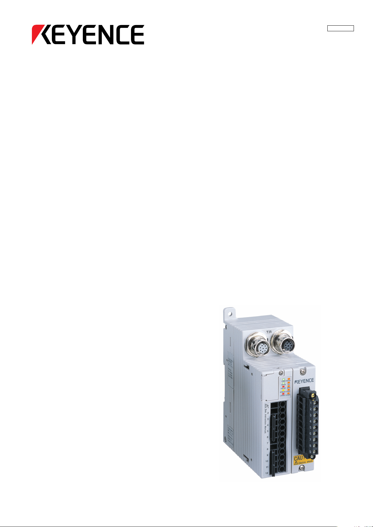
IntelligentSafetyRelayUnit
SL-R11
InstructionManual
NOTICE
Do not attempt to operate or service this machine
until you have read and understood the
instructions written in this manual.
Page 2

Contents
Safety Precautions
1. Safety Headings ....................................................................................................................................iii
2. General Precautions .............................................................................................................................iii
3. Warning ..................................................................................................................................................iv
4. Circuit Design and Wiring .....................................................................................................................iv
5. Testing and Maintenance.......................................................................................................................v
6. About Standards and Regulations........................................................................................................v
7. Accessories ............................................................................................................................................ v
1Specifications
Integration with the SL-C ...................................................................................................................... 1-1
1-1 Part Names .......................................................................................................................................... 1-2
1-2 Specifications ..................................................................................................................................... 1-3
1-3 External Dimensions Diagram .......................................................................................................... 1-3
1-4 Power Supply Precautions ................................................................................................................ 1-4
1-4-1 Power Units that Can Be Used as Power Supplies for SL-C Series and SL-R11 ....................... 1-4
1-4-2 Recommended Dedicated Power Supply Unit ............................................................................ 1-4
2 Functions
ENGLISH
English
2-1 Start Interlock ..................................................................................................................................... 2-1
2-2 Restart Interlock ................................................................................................................................. 2-1
2-3 E-STOP Input ...................................................................................................................................... 2-1
2-4 MPCE (Machine Primary Control Element) Monitor ........................................................................ 2-2
2-5 Main/Sub Setting ................................................................................................................................ 2-3
2-6 TEST Input .......................................................................................................................................... 2-3
2-7 FSD Output ......................................................................................................................................... 2-3
2-8 AUX Output ......................................................................................................................................... 2-3
2-9 Relay Replacement and Terminal Block Installation Removal Function ....................................... 2-4
2-10 Status Indicators ................................................................................................................................ 2-4
2-11 Mode Switch Settings ........................................................................................................................ 2-5
2-12 I/O Circuit ............................................................................................................................................ 2-7
3 Mounting and Installation
3-1 Installation Location .......................................................................................................................... 3-1
3-2 Installation Using a DIN Rail .............................................................................................................. 3-1
3-3 Wall Mounting Using Screws ............................................................................................................ 3-3
3-4 Connection to the SL-U2 Recommended Dedicated Power Supply .............................................. 3-3
i
Page 3

4 Wiring
4-1 Method for Connection to the SL-C Series ...................................................................................... 4-1
4-2 Method for Wiring to the Relay Output Terminal.............................................................................. 4-1
4-2-1 How to Replace the Relay Output Terminal Block ...................................................................... 4-2
4-3 Method for Wiring to Signal Input Terminals.................................................................................... 4-3
4-3-1 Wiring to Start/Restart Input Terminals ....................................................................................... 4-4
4-3-2 Wiring to E-STOP Input Terminals .............................................................................................. 4-5
4-3-3 Wiring to the MPCE Monitor Input Terminal ................................................................................ 4-6
4-3-4 Connecting to Main/Sub Select Input Terminal ........................................................................... 4-7
4-3-5 Wiring to the Test Input Terminal ................................................................................................. 4-8
4-4 About the Light Interference Prevention Connection ..................................................................... 4-9
4-4-1 What is a Light Interference Prevention Connection? ................................................................. 4-9
4-4-2 Parts Required for Connection .................................................................................................... 4-9
4-4-3 Main/Sub Switching Input Setting ............................................................................................... 4-9
4-4-4 Wiring Connections ..................................................................................................................... 4-9
5 Checklist
5-1 List of Pre-use Check Items .............................................................................................................. 5-1
5-1-1 First, Check the SL-R11 Installation Conditions ......................................................................... 5-1
5-1-2 Check the Wiring Before Turning on the Power ......................................................................... 5-1
5-1-3 Check Using an Operation Test While Machine is Stopped ....................................................... 5-1
6 Maintenance
6-1 Regular Inspections ........................................................................................................................... 6-1
6-1-1 Output Relay Inspection .............................................................................................................. 6-1
6-1-2 E-STOP Function Check ............................................................................................................. 6-1
6-2 Relay Circuit Board Replacement ..................................................................................................... 6-1
7Troubleshooting
Troubleshooting .................................................................................................................................... 7-1
8Revision History
Revision History .................................................................................................................................. 8-1
96M13268
ENGLISH
ii
Page 4

Safety Precautions
This manual describes handling, operation, and precautionary information for the Intelligent Safety Relay
Unit (SL-R11). Read this manual thoroughly before operating the SL-R11 in order to understand device
features, and keep this instruction manual readily available for reference.
1. Safety Headings
This instruction manual uses the following headings to display important safety information. Strict adherence
to the instructions next to these headings is required at all times.
ENGLISH
English
DANGER
WARNING
CAUTION
Important:
Note:
Tips
➮
Reference:
WARNING
Failure to follow the instructions may lead to death or serious injury.
Failure to follow the instructions may result in significant harm to machine operators, including death.
Failure to follow the instructions may result in failure to the SL-R11, or to the
machine to which it is installed.
Provides important precautions and restrictions for proper operation.
Provides additional information for proper operation.
Provides useful information for proper operation.
Provides reference pages.
The SL-R11 is a special controller unit for the Safety Light Curtain SL-C Series.
Therefore, be sure to refer to and strictly observe the precautions and warnings
written in the SL-C Series Instruction Manual.
2. General Precautions
•Verify that this device is operating normally in terms of functionality and performance before the start of
work and before the start of device operation.
• KEYENCE is unable to warrant the function or performance of the SL-R11 if it is used in a manner that
differs from the SL-R11 specifications contained in this instruction manual or if the SL-R11 is modified.
• When using the SL-R11 to protect machine operators from a hazardous zone or a hazard, or using it as
safety equipment for any purpose, always follow the applicable requirements, regulations, and laws
(collectively “regulations”) existing in the country or region where the SL-R11 is being used. For such
regulations, contact directly the regulatory agency responsible for occupational safety and health in your
country or region.
• Depending on the type of machine to which the SL-R11 is to be attached, there may be special safety
regulations related to the use, installation, maintenance, and operation of the device, and such safety
regulations must be followed. The responsible personnel must install the SL-R11 in strict compliance with
such safety regulations.
• The responsible personnel must train the assigned personnel for the correct use, installation, maintenance, and operation of the SL-R11. “Machine operators” refers to personnel who have received appropriate training from the responsible personnel and are qualified to operate the device correctly.
• Machine operators must receive specialized training for the SL-R11 and must understand and follow the
safety regulations for the country or region in which they are using the SL-R11.
• When the SL-R11 fails to operate properly, machine operators must immediately stop the use of the
device and report this fact to the responsible personnel.
• The SL-R11 is designed with the assumption that it would be properly installed in accordance with the
installation procedures described in this instruction manual and operated according to the instructions in
this instruction manual. Perform an appropriate installation of the SL-R11 after conducting a sufficient risk
assessment for the target machine.
• This device should be processed as an industrial waste product when being disposed.
iii
Page 5

3. Warning
■ Operators
• In order for the SL-R11 to operate properly, the responsible personnel and machine operators must
follow all procedures described in this instruction manual.
• No person other than the responsible personnel and machine operators should be allowed to install or
test the SL-R11.
• When performing electrical wiring, always follow electrical standards and regulations for the country or
region in which the SL-R11 is being used.
■ Usage environment
• Do not use the device in an environment (temperature, humidity, interfering light, etc.) that does not
conform to the specifications contained in this instruction manual.
• Do not use wireless devices such as cellular phones or transceivers in the vicinity of the SL-R11.
• The SL-R11 is not designed to be explosion-proof. Never use it in the presence of flammable or explo-
sive gases or elements.
• Do not use the SL-R11 in the presence of substances, such as heavy smoke, particulate matter, or
corrosive chemical agents, that may induce deterioration in product quality.
■ Target machine
• The SL-R11 has not undergone the model certification examination in accordance with Article 44-2 of
the Japanese Industrial Safety and Health Law. The SL-R11, therefore, cannot be used in Japan as a
“Safety Device for Press and Shearing machines” as established in Article 42 of that law.
• The machine on which the SL-R11 is to be installed must be susceptible to an emergency stop at all
operating points during its operation cycle. Do not use the SL-R11 for machines with irregular stop times.
• Do not use the SL-R11 for power presses equipped with full-revolution clutches.
• Do not use the SL-R11 to control (stop forward motion, etc.) trains, cars and other transportation vehi-
cles, aircraft, equipment for use in space, medical devices, or nuclear power generation systems.
• The SL-R11 is designed to protect people or objects from entering a machine’s hazardous zone or
hazard. It cannot provide protection against objects or materials that are displaced from the machine's
hazardous zone or hazard, and so implement additional safety measures such as installing safeguards
when there is the possibility of such displacements.
■ Installation
• Install the SL-R11 inside an enclosure such as a control panel that offers a rating of at least IP54 in
accordance with the IEC 60529 standard.
• The SL-R11 is a special controller unit for the Safety Light Curtain SL-C Series, so be sure to connect it
to the SL-C Series when using it.
4. Circuit Design and Wiring
• Always turn off the device power when performing electrical wiring.
•Follow electrical standards and regulations for the country or region in which the SL-R11 is being used
when performing the electrical wiring. Only qualified persons should perform wiring.
• Do not place any cables or electrical lines used in wiring the SL-R11 in the same duct as high-voltage
electrical or power lines or in parallel with such lines.
• Do not extend transmitter and receiver cables over a maximum distance of 30 meters (98.43 ft.).
• Install the mechanism used to reset the interlock (switches, etc.) in a position from which the condition of
the entire hazardous zone can be checked. Do not install the reset mechanism in a position where it can
be operated within the hazardous zone.
• The control outputs (OSSD for SL-C Series or FSD for SL-R11) of the two systems provided in the SL-C
must both be used to build a safety system. Building a safety system with just one of these systems
cannot stop the machine due to a control output malfunction and can result in a serious accident, including serious injury or death to the machine operator.
• The AUX relay output provided in the SL-R11 is not an output for the safety system, so it cannot be used
as a control output (so called FSD) to stop the machine. If using the AUX relay as a relay output to build a
safety system and stop the machine, it could result in the serious injury or death of the machine operator.
• The FSD relays provided in the SL-R11 can be replaced, but when making the replacement, the replacement relay circuit board (OP-42364) provided by KEYENCE must be used. If another relay is used for
replacement, the SL-C Series or SL-R11 might malfunction, or a serious accident causing the serious
injury or death of the machine operator might occur.
• When wiring the SL-R11 output terminal to the machine control circuit of a machine containing the SL-C,
check with the machine manufacturer to make sure the wiring is appropriate for the machine being used
to ensure that the machine can be stopped correctly. If the wiring is not done correctly for the machine, a
serious accident, such as serious injury or death to the machine operator could result.
ENGLISH
iv
Page 6

5. Testing and Maintenance
• Always perform testing in accordance with the test procedures after maintenance, adjustment, or calibration of the target machine or the SL-R11, and before the machine start-up.
• If the SL-C or SL-R11 does not operate properly when tested in accordance with the test procedures
established in this instruction manual, do not operate the machine.
•Periodically examine the machine to verify that all brakes, other stop mechanisms, and control devices
operate reliably and accurately in addition to checking for SL-C and SL-R11.
• The responsible personnel must perform maintenance procedures as established in this instruction
manual at least once every six months to ensure safe device operation.
6. About Standards and Regulations
1) The SL-C and SL-R11 comply with the following UL (Underwriters Laboratories Inc.) Standards
and have received Canada-U.S.-Listing certification from UL.
• UL61496-1 (Type 4 ESPE - Electro-Sensitive Protective Equipment)
• UL61496-2 (Type 4 AOPD - Active Opto-Electronic Protective Device)
2) The SL-C and SL-R11 have not received the model certification examination in accordance with
Article 44-2 of the Japanese Industrial Safety and Health Law. Therefore, the SL-C Series and SLR11 cannot be used in Japan as a “Safety Devices for Presses and Shearing machines” as established in Article 42 of that law.
ENGLISH
English
3) The SL-C Series and SL-R11 have been designed in consideration of the following standards and
regulations. For details regarding the following standards, contact the third-party certification
organization, such as UL.
<Corresponding standards>
• OSHA 29 CFR 1910.212
• OSHA 29 CFR 1910.217
• ANSI B11.1 - B.11.19
• “Guidelines for Comprehensive Safety Standards of Machinery”, July 31, 2007, number 0731001 issued
by, Ministry of Health, Labor, and Welfare in Japan.
7. Accessories
Confirm that the package includes the main unit (SL-R11) and following accessories.
Instruction Manual (this manual) 1 copy
v
Page 7
Chapter 1 Specifications
1 Specifications
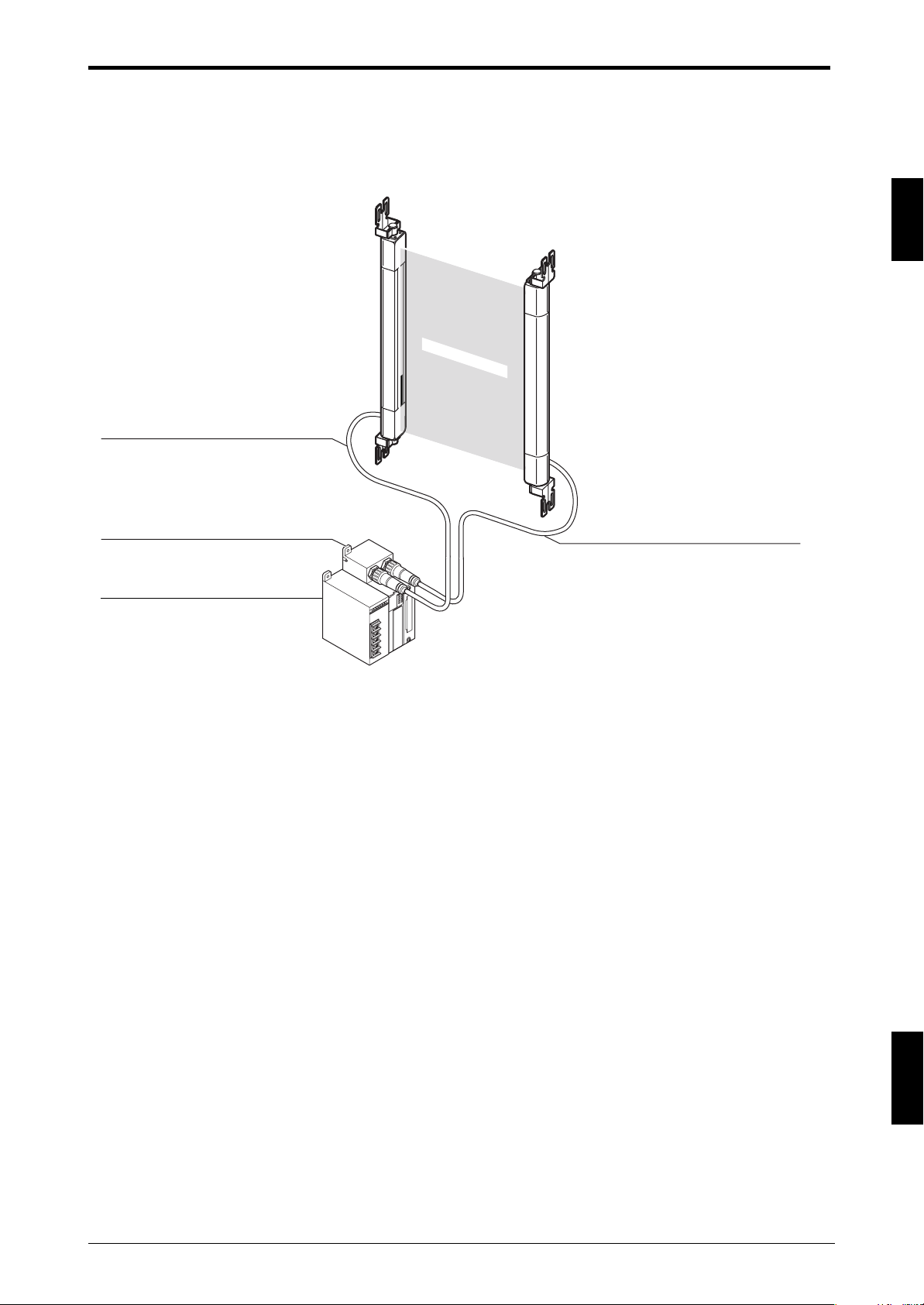
Integration with the SL-C
SL-C Series+ SL-R11 (Intelligent Safety Relay Unit) + SL-U2 (Dedicated power supply unit)
Detection zone
SL-PC5P (5m (16.4 ft.)) cable for transmitter (gray)
* 10 m (32.81 ft.) SL-PC10P cable
1
SL-R11 intelligent safety relay unit
SL-U2 dedicated power supply unit
SL-U2: The UL certified, recommended dedicated power supply unit
SL-PC5P (5m (16.4 ft.)) cable for receiver (black)
* 10 m (32.81 ft.) SL-PC10P cable
1-1
ENGLISH
Page 8
Chapter 1 Specifications
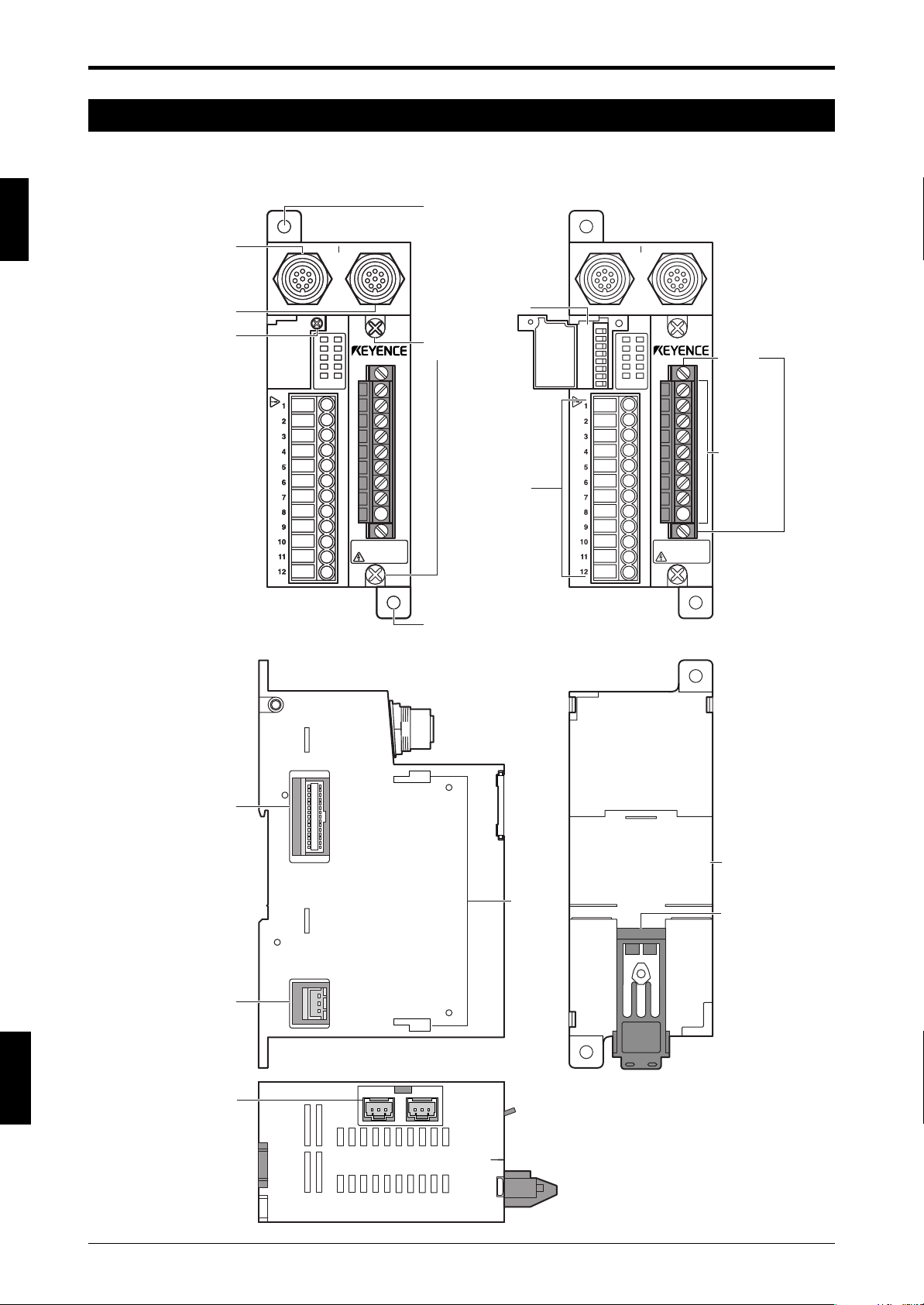
1-1 Part Names
This chapter gives the names of the SL-R11 parts.
1
SL-C Series connector,
SL-C Series connector,
"T" side
"R" side
Mode switch
cover fastener
See Instruction Manual.
See Instruction Manual.
Front view
Hole for mounting screw
(for M4)
T R
T R T R
Mode switches
POWER
RESTART
POWER
FSD-ON
FSD-ON
FSD-OFF
FSD-OFF
INTERLOCK
INTERLOCK
LOCKOUT
LOCKOUT
RESTART
TEST
TEST
MPCE
MPCE
E-STOP1
E-STOP1
E-STOP2
E-STOP2
CAUTION
CAUTION
Electric shock
Electric shock
Relay circuit board
replacement screw
Signal input
terminal block
Hole for mounting screw (for M4)
See Instruction Manual.
Front view
POWER
RESTART
FSD-ON
TEST
FSD-OFF
MPCE
INTERLOCK
E-STOP1
LOCKOUT
E-STOP2
CAUTION
Electric shock
Te rminal
replacement
screws
Relay output
terminal block
ENGLISH
English
SL-R12EX connector
*Covered by tape at
time of shipment.
SL-U2 connector
*Covered by tape at
time of shipment.
Connector for the
light interference
prevention connection
*Covered by tape at
time of shipment.
Side
Rear
SL-U2,
SL-R12EX
mounting
holes
Bottom
DIN rail
mating area
Din rail
lock pin
1-2
Page 9
1-2 Specifications
Chapter 1 Specifications
Model
Safety Light Curtain
Rating
Power supply voltage
Current consumption
Output FSD1, 2
SL-R11
SL-C Series
24V DC ±10% ripple (P-P) 10% max.
150mA max. (for SL-R11 only)
230 V AC 4 A, 30 V DC 2 A (resistive load)
230 V AC 2 A, 30 V DC 1 A (cos ø=0.3) (inductive load)
AUX
125 V AC 0.5 A, 30 V DC 2 A (resistive load)
125 V AC 0.25 A, 30 V DC 1 A (cos ø=0.3) (
Lifespan
Mechanical life: 10 million times min.
Electrical life: 100,000 times min.
Response time FSD1, 2, AUX
Response time during E-STOP input
Environmental
Protective structure
specifications
Ambient temperature
Storage ambient temperature
Relative humidity
Storage ambient humidity
Vibration
24ms (including sensor response time)*
20ms
IP20 (IEC60529) (Install in control panels equal to or
greater than IP54)
-10 to +55 °C (No frost)
-10 to +60 °C (No frost)
35 to 85% RH (No condensation)
35 to 95% RH
10 to 55 Hz double amplitude width 0.7 mm, 20 sweeps
each for X, Y, Z directions
Shock
100 m/s
2
(Approx. 10G) 16ms pulse, in X, Y, Z directions
1,000 times each axis
Material
Weight
Approved EMC EMS
standards
*
EMI
1
Safety
Polycarbonate
380 g max.
UL61496-1
FCC Part 15B Class A
UL61496-1 (type 4 ESPE)
UL61496-2 (type 4 AOPD)
UL508
*1 Evaluated in combination with the SL-C Series
*2 The OFF → ON return time is 150 ms.
inductive
2
1
load)
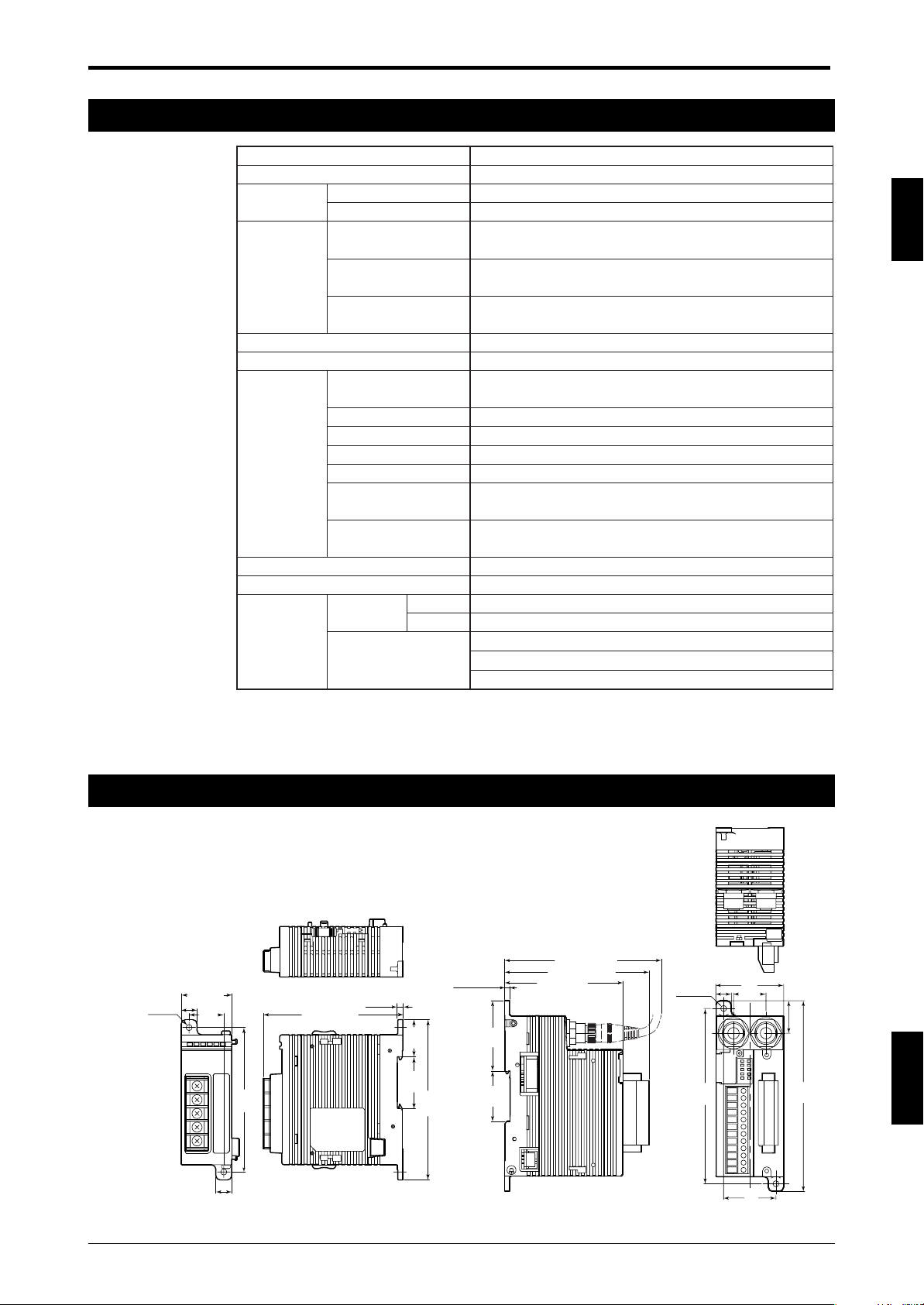
1-3 External Dimensions Diagram
SL-U2 SL-R11
25.8
111
(4.37")
3.5 (0.14")
49.8
(1.96")
35.9
(1.41")
(ø0.17")
2-ø4.2
35 (1.38")
11 (0.43")
24
(0.94")
11
(0.43")
100
(3.94")
(96.6 (3.8"))
3.5
(0.14")
(1.02")
35.9
(1.41")
(112 (4.41"))
(102.3 (4.03"))
83.8 (3.3")
(ø0.17")
2-ø4.2
124
(4.89")
48 (1.89")
11 (0.43")
23 (0.91")
37
(1.46")
23 (0.91")
135
(5.31")
ENGLISH
1-3
Page 10
Chapter 1 Specifications
SL-U2
24V DC
100 to
240 V AC
+
–
PE (GND)*
SL-U2
OC
+
-
N
L
CAUTION
100-240V AC
ONLY
1-4 Power Supply Precautions
1
1-4-1
The power supply units that can be used as the power supply for SL-C Series and SL-R11 must completely
satisfy the following requirements in order to satisfy the requirements of UL61496-1 for the SL-C Series and
SL-R11.
(a) Rated output voltage is 24V DC ±10%.
(b) The power supply to be used shall be a dedicated power supply for the SL-C Series and/or SL-R11 and
(c) The power supply output must satisfy the requirements for a Class 2 Circuit or Limited Voltage/Current
(d) The power supply must comply with the laws, regulations, and standards covering electrical safety,
(e) The output hold time is 20 ms min.
Power Units that Can Be Used as Power Supplies for SL-C Series and SL-R11
shall not be used to supply power to other devices.
Circuit as prescribed by UL508. (This requirement applies only when the SL-C is to be used in North
America.)
electromagnetic compatibility (EMC), etc., for the country or region in which the SL-C Series and/or SLR11 will be used.
1-4-2 Recommended Dedicated Power Supply Unit
The SL-U2 is offered as the SL-C Series dedicated power supply. The SL-U2 is a power supply that
completely satisfies the above requirements.
<Approved standards>
Standard
EN60950-1
Safety EN50178
standard UL60950-1 (R/C)
UL508 (Listing)
EN55011 Class A
EMC standard EN61000-6-2
FCC Part 15B Class A
ENGLISH
English
(*) The PE terminal is a protective conductor terminal that must be connected to a protective earthing
conductor in the building installation.
1-4
Page 11

<Specification>
Chapter 1 Specifications
Model
System
Input power supply voltage
Overvoltage category
Output voltage
Ripple/noise
Output capacity
Environment
Pollution degree
Withstand voltage
Vibration resistance
Shock resistance
Insulation resistance
Power consumption
Supply voltage interruption
Weight (excluding dedicated brackets)
WARNING
Ambient temperature
Relative humidity
For the power supply used for the SL-C Series and SL-R11, always use a power
supply that can fully satisfy the above requirements or use recommended SL-U2
power supply. Otherwise, the UL61496-1 requirements may not be satisfied and the
SL-C Series and SL-R11 may not be recognized as a safety component.
SL-U2
Switching type
AC 100 to 240 V ±10 % (50/60 Hz)
II
DC 24 V ±10 %, Class 2
240 mVp-p or less
1.8 A
-10 °C to +55 °C (non-freezing)
35 % to 85 % RH (non-condensing)
2
AC 1,500 V, 1 min. (between all external terminals and case)
10 to 55 Hz, 0.7 mm (0.03") compound amplitude, 20 sweeps each in X, Y, and Z directions
100 m/s2, 1,000 iterations each in X, Y, and Z directions
At least 50 MΩ (DC 500 V mega, between all external terminals and case)
135VA
10 ms or less
Approx. 240 g
1
1-5
ENGLISH
Page 12

1
Chapter 1 Specifications
MEMO
ENGLISH
English
1-6
Page 13
Chapter 2 Functions
ON
OFF
ON
OFF
Start/restart input
FSD
35ms Max.
ON
FSD
ON
OFF
OFF
20ms Max.
35ms Max.
Start/restart input
E-STOP input
2 Functions
2-1 Start Interlock
This function keeps the FSD turned off when the power to the SL-R11 is turned on. At this time, the FSD will
not turn on even when the SL-C Series connected to the SL-R11 is clear of any obstruction in the detection
zone. In order to cancel the start interlock status (in other words, to turn the FSD ON to allow the machine to
start), the start/restart input must be input when there are no obstacles in the detection zone. This will cause
the FSD to turn on, allowing the cancellation of the start interlock status.
Using this function prevents the machine from being automatically started when the power is turned on, or
when the start switch, etc., is pressed after safety has been confirmed.
➮
For details, See page 4-4 “4-3-1 Wiring to Start/Restart Input Terminals”.
2-2 Restart Interlock
The FSD turns off when an obstacle interrupts the detection zone, and this function keeps the FSD turned off
even after the obstacle is removed from the detection zone. In order to cancel the restart interlock status (in
other words, to turn the FSD ON to allow the machine to restart), the start/restart input must be input when
there are no obstacles in the detection zone. This will cause the FSD to turn on, allowing the cancellation of
the restart interlock status.
This function prevents the machine from automatically starting even when the obstacle detected by the SL-C
Series is removed from the detection zone, so after the safety check is completed, the machine can be
restarted by pressing the start switch, etc.
➮
For details, See page 4-4 “4-3-1 Wiring to Start/Restart Input Terminals”.
Start/restart input timing chart
2
2-3 E-STOP Input
E-STOP input refers to 2 normally closed signal inputs that are used to rapidly stop the machine when the
emergency stop switch or similar button is operated. The SL-R11 has a terminal (E-STOP1 and E-STOP2
input terminals) for receiving the input signal from the emergency stop switch (or similar button) operation, so
the machine can be emergency stopped via the SL-R11. SL-R11 requires the start/restart input in order to
return to the normal operation from an emergency stop state. That is why the SL-R11 requires the start/
restart input to cancel the interlock state in addition to the manual restart of E-STOP signal input.
This function not only makes emergency stopping possible when danger is detected by the SL-C, but can
also cause the FSD provided in the SL-R11 to be operated by E-STOP input from an emergency stop switch,
etc., so it can be used to make output systems uniform.
➮
For details, See page 4-5 “4-3-2 Wiring to E-STOP Input Terminals”.
E-STOP input
2-1
ENGLISH
Page 14

2
ON
OFF
ON
OFF
Clear
Blocked
FSD
24ms Max. 292ms Max.
ON
OFF
ON
OFF
Clear
Blocked
FSD
MPCE monitor
input
24ms Max. 292ms Max.
Lockout
condition
Lockout
condition
MPCE monitor
input
**
ON
OFF
ON
OFF
Clear
Blocked
FSD
MPCE monitor
input
24ms Max. 292ms Max.
ON
OFF
ON
OFF
Clear
Blocked
FSD
MPCE monitor
input
24ms Max. 292ms Max.
**
Chapter 2 Functions
2-4 MPCE (Machine Primary Control Element) Monitor
MPCE (Machine Primary Control Element) is the machine's main control element and is used between the
SL-R11 control output (FSD) and the machine to directly control the machine start/stop. The MPCE uses
safety relays, contactors, and so on, and inputting the feedback signal from these to the MPCE monitor input
terminal provided in the SL-R11 makes it possible to monitor MPCE errors. When an MPCE error causes the
FSD and MPCE operation not to be linked, the SL-R11 immediately turns off the FSD, and the SL-C Series
and SL-R11 go to the lockout condition.
➮
For details, See page 4-6 “4-3-3 Wiring to MPCE Monitor Input Terminal”.
MPCE monitor input
Timing chart when an error occurs
ENGLISH
English
Timing chart when normal
* Depends on response time of machine’s MPCE
2-2
Page 15

Chapter 2 Functions
ON
OFF
ON
OFF
TEST input
FSD
50ms Max. 155ms Max.
WARNING
2-5 Main/Sub Setting
This is set when making a light interference prevention connection to the SL-C Series. Be sure to read about
the light interference prevention connection from the “Safety Light Curtain SL-C Series Instruction Manual.”
The light interference prevention connection function is enabled only when a maximum of 4 SL-R11s are
connected via a light interference prevention cable and the maximum number of beam axes of the SL-C
Series connected to the SL-R11 is 192, only one SL-R11 must be set to the main mode, and all of the other
SL-R11 that are connected via light interference prevention cables must be set to the sub mode.
➮
For details, See page 4-7 “4-3-4 Connecting to Main/Sub Select Input Terminal”.
2-6 TEST Input
The test input forcefully stops light beam transmission from the transmitter by using an external input.
The test input is used to see if the machine connected to the SL-C and SL-R11 can stop within the prescribed time when the FSD turns off.
For example, when the test input is performed with the SL-C in the normal state (when FSD output is on
when all beam axes are clear of any obstruction), the FSD is forced off and only one bar LED of the SL-C
flashes red. (However, this excludes when the Fixed Blanking function is used.)
This test input cannot be used when the SL-R12EX is used and the Programmable Muting Bank function is
enabled. Therefore, the Programmable Muting Bank function must be canceled to enable test input.
TEST input
2
The TEST input cannot be used as an emergency stop input. Be sure to use the ESTOP input when using the emergency stop function.
2-7 FSD Output
The FSD output is the safety relay control output of the SL-R11. There are two FSD outputs, FSD1 and
FSD2. They both have the same operation, but if the contacts of one of the relays gets welded together, the
other relay is turned off. For this reason, FSD1 and FSD2 must be wired to form an AND circuit.
2-8 AUX Output
The AUX relay output is used to monitor the SL-R11’s FSD status using a PLC, etc. The AUX relay operates
the same as the FSD relay, but it cannot be used to build a safety system.
ENGLISH
2-3
Page 16

Chapter 2 Functions
See Instruction Manual.
T R
POWER
FSD-ON
FSD-OFF
INTERLOCK
LOCKOUT
RESTART
TEST
MPCE
E-STOP1
E-STOP2
CAUTION
Electric shock
See Instruction Manual.
Status
Indicators
POWER
FSD-ON
FSD-OFF
INTERLOCK
LOCKOUT
RESTART
TEST
MPCE
E-STOP1
E-STOP2
Input Status Indicators
Status Indicators
No. Name Light Color Operation Status
1POWER Green
Shows the power status.
Lights green when power is supplied.
2 FSD-ON Green
Shows the FSD status.
Lights green when FSD output is on.
3 FSD-OFF Red
Shows the FSD status.
Lights red when the FSD output is off.
4 INTERLOCK Yellow
Lights yellow when the SL-C Series and SL-R11 are in the
start/restart interlock state, or when there is an interlock state from
the E-STOP input.
5 LOCKOUT Red Turns red when the SL-C and SL-R11 are in the lockout condition.
No. Name Light Color Operation Status
6 RESTART Orange Lights orange when the start/restart input terminal is short-circuited.
7 TEST Orange Lights orange when the test input terminal is open.
8 MPCE Orange
Lights orange when the MPCE monitor function is selected and when
the MPCE input terminal is open.
9 E-STOP1 Orange Lights orange when the E-STOP1 input terminal is short-circuited.
10 E-STOP2 Orange Lights orange when the E-STOP2 input terminal is short-circuited.
2
2-9
Relay Replacement and Terminal Block Installation Removal Function
This function makes it possible to replace the relay without changing the SL-R11 wiring. This eliminates
having to redo the wiring each time the relay is replaced and limits wiring mistakes made during rewiring.
➮
For details, See page 6-1 “6-2 Relay Circuit Board Replacement”.
2-10 Status Indicators
Indicators that making it possible to see the (FSD) ON/OFF state or start/restart input terminal input state at
a glance are provided.
Indicators
Status Indicators
ENGLISH
English
Input Status Indicators
2-4
Page 17

2-11 Mode Switch Settings
T R
POWER
FSD-ON
FSD-OFF
INTERLOCK
LOCKOUT
RESTART
TEST
MPCE
E-STOP1
E-STOP2
CAUTION
Electric shock
Mode switch
See Instruction Manual.
MODE SWITCH
MPCE
MONITOR
START
INTERLOCK
RESTART
INTERLOCK
1,5
2,6
3,7
4,8
ON
12345678
No. Mode Name When Enabled * When Disabled
At Factory Shipment
1 MPCE monitor ON OFF OFF
2 Start interlock ON OFF OFF
3 Restart interlock ON OFF OFF
4 Not used
–––
5 MPCE monitor ON OFF OFF
6 Start interlock ON OFF OFF
7 Restart interlock ON OFF OFF
8 Not used
–––
1
Loosen screw
2
Open lid
Chapter 2 Functions
2
Mode switch function and setting states
(*) Both mode switches in the pair must be on.
Ex: The No.1 and No.5 mode switches are on when the MPCE monitor is enabled.
Mode switch setting method
1. Turn off the SL-R11 power.
2. Use a screwdriver to remove the switch cover screws, and then open the switch cover.
Mode switch setting 1 Mode switch setting 2
ENGLISH
2-5
Page 18

2
CAUTION
WARNING
Chapter 2 Functions
3. Refer to the table on page 2-5 and change the mode switches.
4. Close the switch cover, and use a screwdriver to tighten the screws to secure the cover. (The
recommended tightening torque is 0.08 N•m.)
5. Turn on the SL-R11 power, Refer to Chapter 5. Checklist (➮ page 5-1) and check the operation.
• The mode switch settings cannot be changed while the power is on. Be sure to
turn the power off before making changes.
• As shown in the previous table, there are two mode switches provided for each
function. Both mode switches must be on to turn the mode on. (Example: To
enable the start interlock function, mode switches 2 and 6 must be on prior to
supplying power.)
• When finished setting the mode switches, be sure to close the switch cover and
tighten the screws.
• Mode switch settings shall only be set by the responsible personnel for using the
system. It must be made so that the machine operators cannot set the mode
switches.
ENGLISH
English
2-6
Page 19

2-12 I/O Circuit
+5V +5V
Main
Control
Circuit
TEST
input
0V 0V
3
4
0 V 0 V0 V
24 V
MPCE1
MPCE2
Main
Control
Circuit
7
8
E-STOP
control circuit
E-STOP 1
E-STOP 2
+
+
-
-
9
10
11
12
0 V 0 V 0 V
24 V
1
2
TEST input
MPCE monitor
Chapter 2 Functions
2
E-STOP1, E-STOP2
Start/restart input
ENGLISH
2-7
Page 20

2
Main
Control
Circuit
Chapter 2 Functions
FSD1, 2 (Safety relay)
AUX (Relay)1
ENGLISH
English
2-8
Page 21

Chapter 3 Mounting and Installation
3 Mounting and Installation
3-1 Installation Location
Select an appropriate installation location taking into consideration the cable length to the SL-C Series and
the SL-R11 operating environment.
WARNING
Install the SL-R11 in an appropriate enclosure with a minimum protective construction of IP54, such as in the control panel.
The SL-R11 is a dedicated control unit for the safety light curtain SL-C Series, so
be sure to use it with the SL-C Series connected.
3-2 Installation Using a DIN Rail
The SL-R11 can be mounted on a DIN rail. An explanation of how to install or remove the SL-R11 to or from
a DIN rail is given below.
DIN Rail Installation
1. Push hook B down with a screwdriver to release the lock mechanism.
(Front View)
Hook B
3
2. 3.
* Hook A latches on
DIN rail
Hook B
4.
Hook A
*Push controller until hook B
[Locked state] [Unlocked state]
Hook A
Hook B
latches.
DIN rail
Hook B
ENGLISH
* Position hook B so that it is locked.
3-1
Page 22

Chapter 3 Mounting and Installation
DIN Rail Removal Method
(Front View)
DIN rail
Push down using
a screwdriver.
HookB
About installation inside control panels
Always leave at least 30 mm (1.18") of open space between the SL-R11 and other equipment or walls.
3
30mm (1.18")
30mm
(1.18")
* When using the SL-U2, position the SL-U2 at least 30 mm (1.18") from the edge of the cabinet.
Mounting Orientation
Install the SL-R11 in one of the following two orientations:
SL-R11/SL-U2
30mm (1.18")
Ceiling
ENGLISH
English
Floor
3-2
Page 23

Chapter 3 Mounting and Installation
3-3 Wall Mounting Using Screws
The screw fastening holes in the SL-R11 can be used to directly attach the SL-R11 to the wall.
Dimensional drawing
* ➮ See “1-3 External Dimensions Diagram” (page 1-3) for detailed dimensions.
Attach using M4 screws tightened to a recommended torque of 0.7 N•m.
CAUTION
3-4
The SL-R11 is supplied with power by connecting to the SL-U2 dedicated power supply via the connector on
the side of the SL-R11.
The connector is covered with a seal to protect it, so remove the seal before making the connection.
Connection to the SL-U2 Recommended Dedicated Power Supply
The SL-R11 cannot be attached to the DIN rail and to the wall by screws at the
same time.
2-ø4.2
124
37
3
* Install while being careful
of the connectors
The connection methods are as follows.
[1] When mounting on a DIN rail
1. Refer to the figure above, and peel off the power supply connector seal.
2. Mount both the SL-R11 and SL-U2 to the DIN rail.
3. Slide one of the units to connect them both together.
4. Slide the SL-U2 connection hooks to fasten the units together.
ENGLISH
3-3
Page 24

3
Chapter 3 Mounting and Installation
[2] When mounting on the wall with screws
1. Refer to the previous figure, and peel off the power supply connector seal.
2. Refer to the previous, figure, and connect the two units.
3. Slide the SL-U2 connection hooks to fasten the units together.
4. Use M4 screws tightened to a recommended torque of 0.7 N•m to mount both of the units to the
wall.
ENGLISH
English
3-4
Page 25

Chapter 4 Wiring
WARNING
Connector for Receiver (black)
Connector for transmitter (gray)
Transmitter cable (gray)
SL-PC PT or
SL-CC10PT
Receiver cable (black)
SL-PC PR
or SL-CC10PR
Terminal No. Name
1, 2 FSD 1
3, 4 FSD 2
5, 6 AUX
7 Not used
8+ 24V
90V
FSD1
FSD2
AUX
Unused
+24V
0V
T R
POWER
FSD-ON
FSD-OFF
INTERLOCK
LOCKOUT
RESTART
TEST
MPCE
E-STOP1
E-STOP2
CAUTION
Electric shock
1
2
3
4
5
6
7
8
9
See Instruction Manual.
MODE SWITCH
MPCE
MONITOR
START
INTERLOCK
RESTART
INTERLOCK
1,5
2,6
3,7
4,8
MODE SWITCH
MPCE
MONITOR
START
INTERLOCK
RESTART
INTERLOCK
1,5
2,6
3,7
4,8
M
MPCE 1
MPCE 2
IN
OUT
PLC
24V
0V
MPCE 1
MPCE 2
T R
POWER
FSD-ON
FSD-OFF
INTERLOCK
LOCKOUT
RESTART
TEST
MPCE
E-STOP1
E-STOP2
CAUTION
Electric shock
See Instruction Manual.
MODE SWITCH
MPCE
MONITOR
START
INTERLOCK
RESTART
INTERLOCK
1,5
2,6
3,7
4,8
+24V 0V
Machine Control
4 Wiring
4-1 Method for Connection to the SL-C Series
• The SL-C Series can be connected to the SL-R11 using only the following cable
combinations: SL-PC5P/SL-PC10P and SL-CC10PT/SL-CC10PR.
• The maximum length of the SL-C Series connection cables (transmitter and
receiver cables) is 30m (98.43 ft.) each.
• Using cables that exceed 30m (98.43 ft.) in length could result in unstable operation of the SL-C Series and SL-R11 and cause a serious accident leading to
serious injury or death of the machine operator.
Use the special cables to connect the SL-C and SL-R11 as shown in the figure below. Connect and secure
the cables from the SL-C to the connectors for receiver and transmitter provided on the SL-R11.
Connection 2 Connection 1
4
* Use the following minimum bend radius when routing SL-C Series cables: 10mm (0.39") or greater for the
base of the connector that is connected to the SL-R11, and 5mm (0.2") or greater for all other positions.
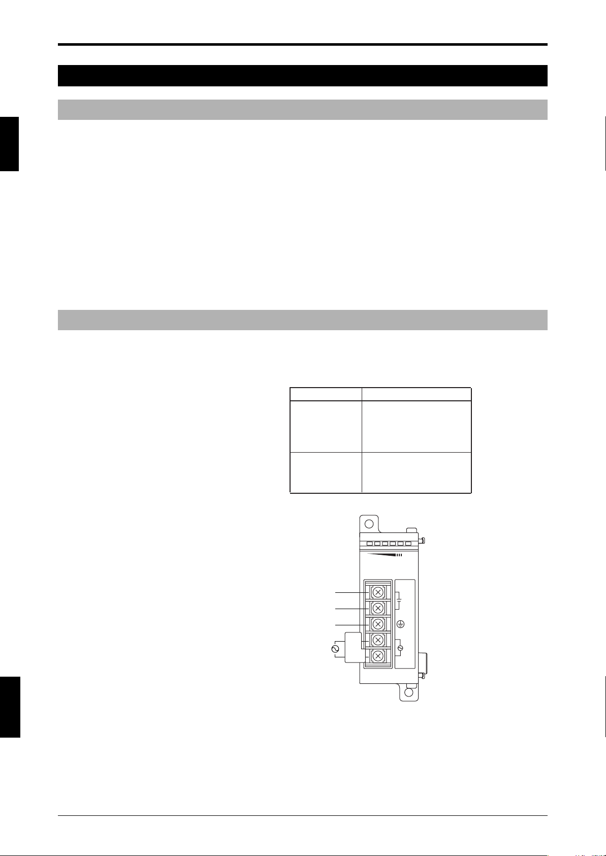
4-2 Method for Wiring to the Relay Output Terminal
As shown in the table below, the SL-R11 has a relay output terminal block. This is a quick-disconnect type
terminal block.
Relay output terminal Wiring example
ENGLISH
4-1
Page 26

4
Insert wire
Loosen with flat-head
screwdriver.
Tighten with flat-head
screwdriver.
WARNING
Chapter 4 Wiring
• Tightening torque 4.4 lb•in (0.5 N•m)
• Wire rating AWG # 22 to 12 (Stranded only, Copper only, min. 60 °C)
• Cable stripping dimension
7mm
(0.28")
4-2-1 How to Replace the Relay Output Terminal Block
Loosen the two terminal block replacement screws and pull the terminal block upwards. To install the new
terminal block, tighten the two terminal block replacement screws after attaching the terminal block and the
SL-R11. (The recommended tightening torque is 0.4 N•m.)
ENGLISH
English
• Always turn off the power supply when performing electrical wiring.
• The two control outputs (FSDs) provided in the SL-R11 must both be used to
build a safety system. Building a safety system with just one of these outputs
could cause the system not to stop due to a control output malfunction, which
could result in a serious accident, including serious injury or death to the machine operator.
• The AUX relay output provided in the SL-R11 is not an output for the safety
system, so it cannot be used as a control output (so called FSD) to stop the
machine. Using an AUX relay as an output relay is used to build a safety system
and stop the machine, could result in the serious injury or death.
• When wiring the SL-R11 output terminals to the control circuit of a machine
containing the SL-C, check with the machine manufacturer to make sure the
wiring is appropriate for the machine being used to ensure that the machine can
be stopped correctly. If the wiring is not done correctly for the machine, a serious
accident, such as serious injury or death to the machine operator could result.
•Follow electrical articles, regulations, standards, and laws for the country or
region in which the SL-R11 is being used when performing electrical wiring.
• Do not place cables or electrical lines used in wiring the SL-R11 in the same duct
as high-voltage electrical or power lines or in parallel with such lines.
4-2
Page 27

Chapter 4 Wiring
Terminal No. Name
1, 2 Start / Restart input
3, 4*
1
TEST input
5, 6*
1
M/S SELECT input *
2
7, 8 MPCE MONITOR input
9, 10*
1
E-STOP1 input
11, 12*
1
E-STOP2 input
*1 When the SL-R11 is shipped, short bars are
connected across terminal Nos. 3 and 4, 5 and 6,
9 and 10, and 11 and 12.
To use the functions assigned to these terminals,
remove the short bar and wire the terminal.
*2 Main/Sub select input
See Instruction Manual.
MPCE2MPCE1
T R
POWER
FSD-ON
FSD-OFF
INTERLOCK
LOCKOUT
RESTART
TEST
MPCE
E-STOP1
E-STOP2
CAUTION
Electric shock
2
1
3
Tighten with flat-head
screwdriver
Insert wire
Loosen with flat-head
screwdriver
4-3 Method for Wiring to Signal Input Terminals
As shown in the table below, the SL-R11 is provided with a signal input terminal block. First loosen the
terminal block screws, and then retighten the terminal block screws after inserting the signal cables.
Input terminals
4
• Tightening torque 4.4 lb•in (0.5 N•m)
• Wire rating AWG #22 to 14 (Stranded only, Copper only, min. 60 °C)
• Cable stripping dimension
10mm
(0.39")
ENGLISH
4-3
Page 28

4
Start / Restart
input
TEST input
M/S SELECT
input
MPCE
MONITOR input
E-STOP1
input
E-STOP2
input
ON
OFF
ON
OFF
Start/Restart
input
FSD
35ms
10 ms. min.
WARNING
CAUTION
Chapter 4 Wiring
4-3-1 Wiring to Start/Restart Input Terminals
The start/restart input terminals are used to connect a signal input (switch, etc.) to cancel the interlock
condition when the machine starts/restarts is run.
To use the start/restart interlock function and E-STOP function, a signal input, such as a switch, must be
connected to this input terminal. Refer to the following wiring diagram when wiring.
Wiring diagram
Timing chart
ENGLISH
English
4-4
• When wiring the signal input, such as a switch, to this terminal, install the mechanism used to reset the interlock in a position from which the condition of the
entire hazardous zone can be checked. Do not install the reset mechanism in a
position where it can be operated within the hazardous zone.
• Confirm that there are no people or objects in the hazardous zone before operating the start/restart input means.
• Use a normally open device, for the start/restart input.
• The start/restart input terminals connect to the 24V DC output terminal. Therefore, the device, using the start/restart input must be rated for 24V DC or higher.
However, because this terminal is only used for start/restart input, it cannot be
used to supply power to other devices.
Page 29

Chapter 4 Wiring
Start / Restart
input
TEST input
M/S SELECT
input
MPCE
MONITOR input
E-STOP1
input
E-STOP2
input
ON
FSD
ON
OFF
OFF
20ms Max.
35ms Max.
Start/restart input
E-STOP input
10 ms. min.
WARNING
4-3-2 Wiring to E-STOP Input Terminals
The E-STOP input terminals are used to connect a signal input, such as an emergency stop switch, for
stopping the machine to which the SL-C is installed. The terminals are normally closed terminals, so jumpers
are placed across the terminals at the time of shipment to create a short-circuit across the terminals.
When an emergency stop switch is connected to the E-STOP input terminal, an emergency stop switch that
satisfies the following specifications must be used.
When a signal is input to the E-STOP input terminal, the FSD turns off and the machine stops.
(For detailed requirements in addition to the following, refer to ISO13850.)
1.The emergency stop switch actuator shall be a mushroom-shaped push button or a rope type.
2.The emergency stop switch actuator shall be colored red.
3.There are positive opening operation, and the normal status of the contact is closed.
4.Resetting the emergency stop switch shall only be possible as the result of a manual action on the
emergency stop switch itself. (In other words, it is a self-tripping switch.)
5.Have a third-party certification organization (UL, etc.) verify that the emergency stop switch complies
with the regulations, standards, and laws of the country or region where the SL-R11 will be used.
In addition, when connecting one emergency stop switch to the E-STOP input terminal, the wiring is as
shown below, so refer to the following wiring.
Wiring diagram
Timing chart
4
• Depending on how the emergency stop switch is used, the electrical articles,
regulations, standards, and laws of the country or region where the SL-C Series
and SL-R11 will be used must be complied with, so refer to all related requirements when using these devices.
• When no wiring is connected to the E-STOP input terminal, do not remove the
jumper (short bar) attached to the E-STOP input terminal at factory shipment.
• The SL-C Series and SL-R11 interlock states are designed to remain unchanged
even if the emergency stop switch is reset. To restart the SL-C Series and SLR11, emergency stop switch reset and restart input are required, be sure to
➮
See “4-3-1 Wiring to Start/Restart Input Terminals” (page 4-4) regarding restart
input
.
4-5
ENGLISH
Page 30

4
MPCE2MPCE1
Start / Restart
input
TEST input
M/S SELECT
input
MPCE
MONITOR input
E-STOP1
input
E-STOP2
input
ON
OFF
ON
OFF
Clear
Blocked
FSD
24ms Max. 292ms Max.
ON
OFF
ON
OFF
Clear
Blocked
FSD
MPCE monitor
input
24ms Max. 292ms Max.
Lockout
condition
Lockout
condition
MPCE monitor
input
* *
ON
OFF
ON
OFF
Clear
Blocked
FSD
MPCE monitor
input
24ms Max. 292ms Max.
ON
OFF
ON
OFF
Clear
Blocked
FSD
MPCE monitor
input
24ms Max. 292ms Max.
* *
Chapter 4 Wiring
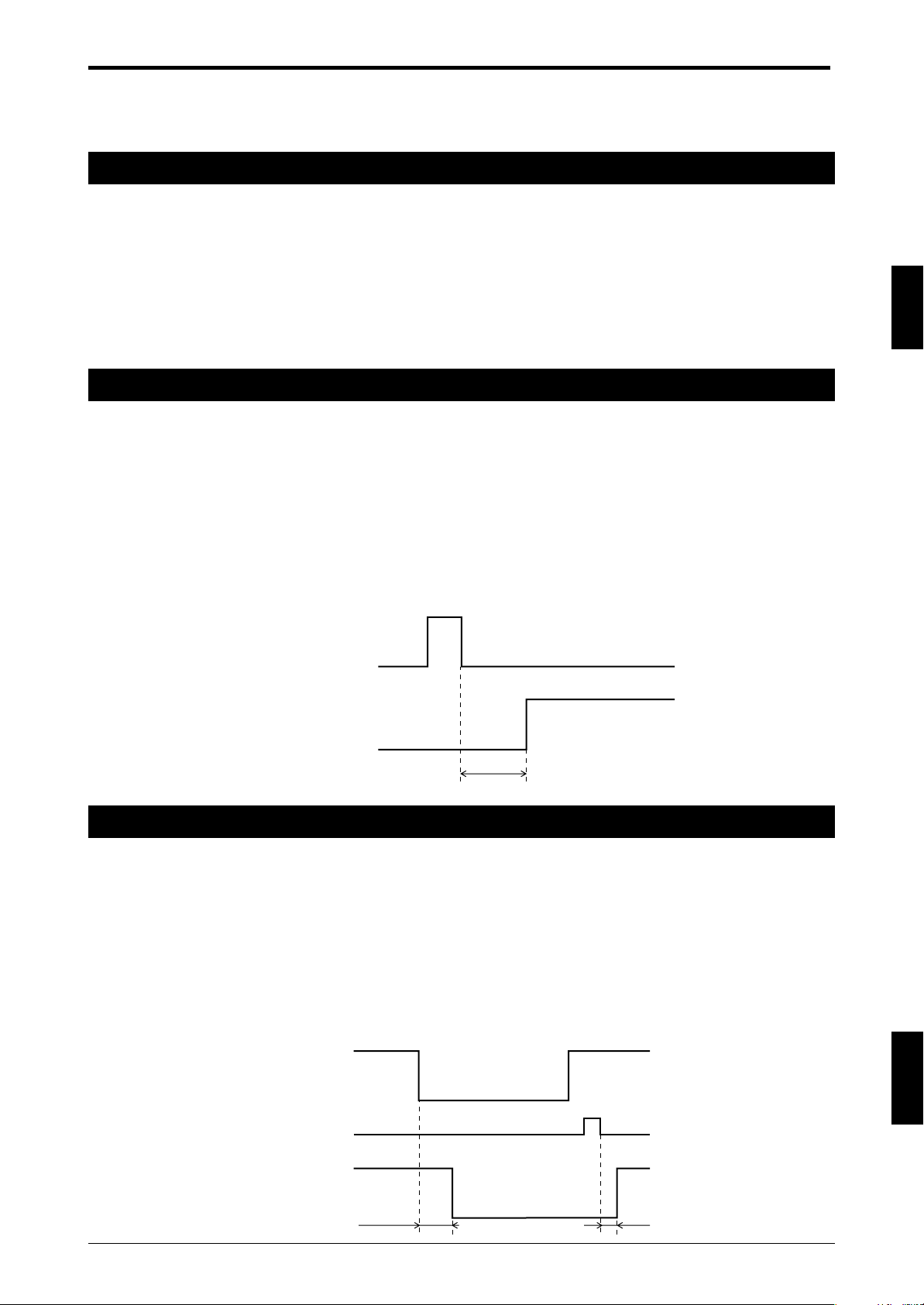
4-3-3 Wiring to the MPCE Monitor Input Terminal
Tw o MPCEs are used in the machine control circuit. The MPCE monitor function monitors the operation of
MPCE1 and MPCE2 to detect control circuit errors and MPCE unit errors that prevent the transmission of the
FSD output signal to the machine. When an error is detected, the SL-C Series and SL-R11 go to the lockout
condition. To enable this feature, it is necessary to set the mode switches of MPCE monitor to “Enable”
according in the instructions in section 2-11 “Mode Switch Settings” (➮ page 2-5).
Use a device for the MPCE that has normally closed contacts and that has a maximum response delay time
of 292ms.
In addition, when connecting a MPCE to the MPCE monitor input terminal, the wiring is as shown below, so
refer to the example when wiring.
Wiring diagram
ENGLISH
English
1.Wire the MPCE1 relay coil to FSD1.
2.Wire the MPCE2 relay coil to FSD2.
3.To enable the MPCE monitor, connect the MPCE1 normally closed contact and MPCE2 normally closed
contact in series, and then connect them to the MPCE monitor input terminal.
Timing chart
Timing chart when an error occurs
Timing chart when normal
* Depends on response time of machine’s MPCE
4-6
Page 31

Chapter 4 Wiring
WARNING
CAUTION
Main Sub
• Use an appropriate MPCE device after referring to all of the standards and
regulations relating to the MPCE to be used in the machine.
•To use the MPCE monitor, make the proper wiring for the machine control
system, and have the machine manufacturer check the wiring for correctness to
ensure that the machine can be properly stopped. If the wiring is not done
correctly for the machine, the MPCE monitor could malfunction, resulting in a
serious accident that could cause serious injury or death to the machine operator.
• Only one MPCE monitor input terminal system exists in the SL-R11. Therefore, to
use the MPCE monitor, the feedback signal output from the MPCE1 and MPCE2
must be connected in series. If they are not connected in series, the MPCE
monitor could malfunction, resulting in a serious accident that could cause
serious injury or death to the machine operator.
4-3-4 Connecting to Main/Sub Select Input Terminal
The main/sub select input terminal is used when a light interference prevention connection is made to prevent SL-C Series light interference. Be sure to read the “Safety Light Curtain SL-C Series Instruction Manual”
regarding interference prevention connections.
When making a light interference prevention connection, main and sub settings must be made for the SLR11 connected to the SL-C Series. At this time, follow the instructions below to wire to this terminal.
4
In case of main mode: Use the attached jumper to short-circuit between these terminals.
In case of sub mode: Remove the attached jumper.
Selecting between the main and sub is not possible during SL-C Series and SLR11 operation. Be sure to turn off the power before making the settings using the
above wiring.
ENGLISH
4-7
Page 32

4
Start / Restart
input
TEST input
M/S SELECT
input
MPCE
MONITOR input
E-STOP1
input
E-STOP2
input
ON
OFF
ON
OFF
TEST input
FSD
50m Max. 155ms Max
Chapter 4 Wiring
4-3-5 Wiring to the Test Input Terminal
Use for test Input.
During normal operation: Short-circuit between 3 and 4
Test mode: Open between 3 and 4
Timing chart
ENGLISH
English
4-8
Page 33

Chapter 4 Wiring
Name Model Manufacturer Quantity Notes
Connector DF1E-3S-2.5C
HIROSE
2 KEYENCE also offers OP-42365 as an option
Crimp terminal
DF1B-2022SC
ELECTRIC CO., LTD.
6 (set of 2 connectors and 6 crimp terminals).
Cable
2-wire shielded cable
Supplied by customer.
AWG #20 to 22
1 (30 m
(98.43 ft.)
or less)
Remove the sticker on
the rear of the SL-R11.
Pin No. Description
1 Interference prevention (-)
2 Shielding (0 V)
3 Interference prevention (+)
3
2
1
Rear of SL-R11
Wiring Diagram
3
2
1
3
2
1
Connector 2-wire shielded cable Connector
4-4 About the Light Interference Prevention Connection
4-4-1 What is the Light Interference Prevention Connection?
Be sure to read the “Safety Light Curtain SL-C Series Instruction Manual” if you plan to use this feature. By
establishing a light interference prevention connection, you can prevent light interference between 2 or more
sets of SL-C Series that are connected to the SL-R11. This feature is active when the total number of connected SL-R11 units is 4 or less.
To enable the light interference prevention function, the power to the main SL-R11 units and sub SL-R11
units must be turned on. (If the power supply of a sub unit is turned OFF during operation, this unit and the
inferior sub units to it go to lockout condition and their operations are stopped.)
4-4-2 Parts Required for Connection
4
4-4-3 Main/sub Switching Input Setting
One of the SL-R11 units sharing the light interference prevention connection should be set as the main, while
all remaining SL-R11 units are configured as subs. See “4-3-4 Connecting to Main/Sub Select Input Terminal”
(➮ page 4-7) for information about how to make this setting.
4-4-4 Wiring Connections
ENGLISH
4-9
Page 34

4
<Main>
<Main>
<Sub>
<Sub> <Sub> <Sub>
When connecting 2 units
When connecting 4 units
WARNING
Chapter 4 Wiring
Connect the SL-R11 units after assembling the connectors, crimp terminals, and cables.
Using cables other than those specified or with a length in excess of 30m (98.43 ft.)
may result in significant harm to machinery operators, including serious injury or
death.
Do not strip away more than 100mm (3.93") of the shielding wire when connecting
system wiring.
ENGLISH
English
4-10
Page 35

Chapter 5 Checklist
5 Checklist
5-1 List of Pre-use Check Items
After the SL-C Series and SL-R11 are installed, the responsible personnel shall use the following checklist to
check operation. The following checklist contains the minimum necessary items for using the SL-R11. The
required check items will differ depending on the laws and regulations of the country or region of the machine
in which the SL-R11 is being used, so KEYENCE corporation strongly recommends that the responsible
personnel add any required check items to this check list.
This check list is only to be used for the SL-R11, so refer to the SL-C Series Instruction Manual to create a
checklist based on using the SL-R11 in combination with SL-C Series.
5-1-1 First, Check the SL-R11 Installation Conditions
The SL-R11 is installed in an appropriate enclosure with at least an IP54 rating (in a control box,
❏
etc.).
The machine to be controlled by the SL-R11 must be capable of receiving the output signal from
❏
the SL-R11 FSD and of emergency stops.
For the method to reset the interlock (switches, etc.), the SL-R11 must be installed in a position
❏
where the entire hazardous zone or source of hazard can be checked and where it cannot be
operated from within the hazardous zone.
5-1-2 Check the Wiring Before Turning on the Power
For the SL-R11 power supply, only a dedicated power supply should be used to supply power to the
❏
SL-C Series light curtain system, including the SL-R11. No other device can be supplied from the
same power supply.
To supply power to the SL-R11, KEYENCE Corporation strongly recommends that the SL-U2 be
❏
used, but a different DC24V power supply that satisfies the power supply conditions specified in
this instruction manual may be used. (Be sure to refer to the power supply items.)
The transmitter cable (gray) is correctly connected to the transmitter cable connector, and the
❏
receiver cable (black) is correctly connected to the receiver cable connector.
When connecting 2 or more SL-R11s using the light interference prevention connections, correctly
❏
use the light interference prevention cable prescribed in this instruction manual.
The FSD is connected to the machine's control circuit, and the wiring is such that the machine can
❏
be correctly stopped by the FSD output.
When the E-STOP function is used, the wiring is such that the machine can be correctly stopped by
❏
the E-STOP input.
When 2 or more emergency stop switches are connected to the E-STOP terminal, they are con-
❏
nected in series.
5-1-3 Check Using an Operation Test While Machine is Stopped
When the start interlock is enabled, the SL-C Series and SL-R11 go to the start interlock state and
❏
the machine stops.
When the restart interlock is enabled and the SL-C is in the blocked beam state, the SL-C Series
❏
and SL-R11 go to the interlock state and the machine stops.
5
ENGLISH
5-1
Page 36

Chapter 6 Maintenance
6 Maintenance
6-1 Regular Inspections
6-1-1 Output Relay Inspection
Refer to the SL-C instruction manual and put the SL-C Series in the blocked beam state, or use the test input
and turn this unit's FSD output off.
At this time, confirm that both FSD outputs are off, and that the MPCE (machine primary control element)
which is connected to the FSD is off.
➮
If the relay is fused or malfunctioning,
it.
See 6-2 “Relay Circuit Board Replacement” (➮ page 6-1)
6-1-2 E-STOP Function Check
1. Check to make sure there are no errors in the wiring between the SL-R11 and E-STOP switch.
2. If the wiring insulation is damaged, replace it immediately.
3. Actually operate the E-STOP function and check to make sure the SL-R11's FSD output terminal turns off and that the machine stops. In addition, check the SL-R11 indicator and confirm
that the LEDs for both E-STOP1 and E-STOP2 are off.
and service
6
4. Reset the E-STOP switch. At this time, check that the FSD outputs are kept off. (The restart
interlock function will automatically operate when the FSDs are turned off by the E-STOP even
when the restart interlock function is not used.)
5. Use the restart input to reset the FSD output. At this time, if the SL-R11 goes to lockout condition and the FSD output is not recovered, there is probably a wiring problem or an E-STOP
switch failure, etc., so immediately stop using the machine and make repairs. Absolutely do not
use the machine until the repairs are completed.
6-2 Relay Circuit Board Replacement
The output relay provided in the SL-R11 is designed to be user-replaceable, and there is no need to
reconfigure the wire connections to the relay output terminal.
This section explains how to replace the relay circuit board.
1. Prepare a replacement relay circuit board (OP-42372).
2. Turn off the power to the SL-R11.
3. Turn off the power to the devices connected to the SL-R11 FSD output terminal and AUX output
terminal.
4. Remove the relay output terminal from the replacement relay board according to the instructions in section 4-2-1 “How to replace the relay output terminal block” (➮ page 4-2).
5. Refer to the figure below and remove the relay circuit board from the SL-R11.
ENGLISH
English
6-2
6-1
Page 37

Chapter 6 Maintenance
6. Install the new relay circuit board in the SL-R11 and tighten the screws. (Recommended tightening torque is 0.6 N•m)
7. Attach the relay output terminal removed in Step 4 to the new replacement relay board
according to the instructions in section 4-2-1 “How to replace the relay output terminal block
(➮4-2)”.
8. Refer to “Chapter 5. Checklist” (➮ page 5-1) and check the operation.
WARNING
•A high voltage is generated in the FSD output and AUX output terminals, so
before beginning the replacement work, turn off the power to the SL-C Series
and SL-R11 as well as the power of the devices connected to the FSD output
and AUX output terminals. Leaving the power on could result in electric shock.
• When the relay needs to be replaced, replace it with the replacement relay circuit
board (OP-42372) provided by KEYENCE. Do not use parts from another manufacturer. Using other parts could cause the SL-C to malfunction, and a serious
accident causing a serious injury or death.
6
6-3
6-2
ENGLISH
Page 38

Chapter 7 Troubleshooting
SL-C08H
RATED VOLTAGE / CURRENT
TYPE OF POWER SUPPLY
RESPONSE TIME
DETECTION ZONE (PROTECTION ZONE)
DETECTION CAPABILITY
EAA
ENCLOSURE RATING
AMBIENT TEMPERATURE
Transmitter
24V DC 55mA Class2
See Instruction Manual
15ms
140mm(185mm)
φ 25/ φ 45/ φ 65/ φ 85mm
± 2.5˚ (3m or more)
IP65
-10˚C to 55˚C
SL-C08H
RATED VOLTAGE / CURRENT
TYPE OF POWER SUPPLY
RESPONSE TIME
DETECTION ZONE (PROTECTION ZONE)
DETECTION CAPABILITY
EAA
ENCLOSURE RATING
AMBIENT TEMPERATURE
Receiver
24V DC 67mA Class2
See Instruction Manual
15ms
140mm(185mm)
φ 25/ φ 45/ φ 65/ φ 85mm
± 2.5˚ (3m or more)
IP65
-10˚C to 55˚C
Bar LED display status
Receiver
Description
Causes and solutions
Transmitter
1 and all lamps
alternately light up
1 lights up
Transmitter error
• Reconnect the transmitter and cable as described in section 2-3-1 “Connecting
Cable Installation” (➮2-7) in the SL-C manual.
• Reconnect the SL-R11 and transmitter connectors as described in section 4-1
“Method for Connection to the SL-C Series” (➮4-1) in the SL-R11 manual.
• The transmitter is damaged. Replace the sensor.
• Remove any extension cable from the transmitter side (Receiver Side).
• Remove any series connection heads and retest with only the first set of heads.
2 lights up
Receiver error
• Reconnect the receiver and cable as described in section 2-3-1 “Connecting
Cable Installation” (➮2-7 ) in the SL-C manual.
• Reconnect the SL-R11 and receiver connectors as described in section 4-1
“Method for Connection to the SL-C Series” (➮4-1) in the SL-R11 manual.
• The receiver is damaged. Replace the sensor.
• Remove any extension cable from the transmitter side (Receiver Side).
• Remove any series connection heads and retest with only the first set of heads.
3 lights up 3 lights up
SL-R11 error
• Reconnect the SL-R11 and SL-C connectors as described in section 4-1
“Method for Connection to the SL-C Series” (➮4-1) in the SL-R11 manual.
• The wrong cable is being used to connect the SL-R11 and SL-C. Use the correct
type of cable as described 4-1 “Method for Connection to the SL-C Series” (➮4-
1) in the SL-R11 manual.
• The SL-R11 mode switch has not been set properly. Follow the instructions in
section 2-11 “Mode switch setting (➮2-5)” of this manual to set the switch
properly.
• The short bar attached when shipped from the factory is detached or loose.
Attach the short bar according to the function setting to be used. If it is already
attached, tighten the screws on the terminal block.
• If the MPCE monitor function is being used, the MPCE is damaged or has not
been wired properly. Check the MPCE and its wiring as described in section 43-3 “Wiring to the MPCE Monitor Input Terminal” (➮4-6) in the SL-R11
manual.
• The SL-R11 is damaged and needs to be replaced.
4 lights up
Inconsistent
number of
transmitter and
receiver beam
axes
• Different models of transmitter and receiver are being used so that the number of
beam axes does not match. Use a proper combination of models.
• If being connected in series, use the same model and number of connected SL-C
units on both the transmitter and receiver sides of the system.
5 lights up
Light interference
Interfering
light received
• The receiver is receiving light that originated in an SL-C transmitter that is not
its matched pair. Fix this problem as described in either section 2-3-5 “Light
Interference Prevention Method” (➮2-12) in the SL-C manual or section 4-4
“About the Light Interference Prevention Connection” in the SL-R11 manual
(➮4-9).
• The receiver is receiving light originating from an inverter fluorescent light or
another sensor. Prevent this light from entering the receiver by adjusting the
location at which the sensor is installed or installing a masking plate.
6 lights up 6 lights up
Communications
error
• Reconnect the SL-R11 to the SL-C as described in section 4-1 “Method for
Connection to the SL-C Series” (➮4-1) in the SL-R11 manual.
• If light interference prevention connections have been made, the main/sub switch
is set so that there are multiple mains configured. Always configure the system
so that there is only 1 main, as described in section 4-3-4 “Connecting to
Main/Sub Select Input Terminal” (➮4-7) in the SL-R11 manual.
• If the unit has been configured as a sub with the light interference prevention
connection, the power has been cut to the sensor that is configured for either the
main or the sub that is connected closer to the main. Be careful not to cut power
to only some of the connected sensors.
2 and all lamps
alternately flash
4 and all lamps
alternately light up
5 and all lamps
alternately light up
<Display Indicator>
7 Troubleshooting
When either the Safety Light Curtain SL-C Series or the Intelligent Safety
Relay Unit SL-R11 experiences an error, it is possible to determine the cause
of the error by referring to the state of the bar LED display on the SL-C.
When the lock-out indicator (orange) is flashing, the device can be returned
to normal operation by turning it off and then on again once the cause of the
problem has been rectified.
The following stickers have been affixed to transmitters and receivers. Verify
the on/off status of the LED after checking the orientation of the system's
transmitters and receivers.
Tr ansmitter Receiver
7
ENGLISH
English
7-2
7-1
LOCKOUT
1. Lockout indicator
8
7
6
5
2. Bar LED
4
3
2
1
ON/OFF
3. Output
FUNCTION
4. Function indicator
status indicator
Page 39

Chapter 7 Troubleshooting
Bar LED display status
Receiver
Description Causes and solutions
Transmitter
OSSD error
• The cable connected to the SL-C has its transmitter and receiver ends reversed.
Connect the cable properly as described in section 2-3-1 “Connecting Cable
Installation” (➮2-7) in the SL-C manual.
• Reconnect the SL-R11 to the SL-C as described in section 4-1 “Method for
Connection to the SL-C Series” (➮4-1) in the SL-R11 manual.
• The OSSD is damaged. Replace the sensor.
7 lights up 7 and all lamps
alternatively flash
8 lights up 8 lights up
FSD error
• The SL-R11’s FSD has failed due to contact adhesion or a similar cause.
Replace the relay board as described in section 4-2-1 “How to replace the relay
output terminal block” (➮4-2) in the SL-R11 manual.
•Verify that the relay board has been installed properly as described in section 42-1 “How to replace the relay output terminal block” (➮4-2) in the SL-R11
manual and 6-2 “Relay Circuit Board Replacement” (➮6-1) in the SL-R11
manual.
1 flashes 1 flashes
No beam is being
received
• Either the beam axes are completely misaligned, or are being blocked by a
shielding object. Readjust the beam axes as described in section 3-9 “Beam Axis
Adjustment” (➮3-8) in the SL-C manual.
•Verify that the operating distance does not fall outside of the range indicated by
the specifications.
• The switch setting is not correct. Configure the switch properly as described in
section 4-3-4 “Connecting to Main/Sub Select Input Terminal” (➮4-7) in the SLR11 manual.
• The test input terminal is open. Short the test input terminal during normal use
as described in section 4-3-5 “Wiring to the Test Input Terminal” (➮4-8) in the
SL-R11 manual.
Multiple lamps
light up red
Multiple lamps
light up red
Beam is being
blocked
• Some of the beam axes are misaligned or are being blocked by an obstacle.
Readjust the beam axes as described in section 3-9 “Beam Axis Adjustment”
(➮3-8) in the SL-C manual.
•Verify that the operating distance does not fall outside of the range indicated by
the specifications.
All lamps flash greenAll lamps flash green
Unstable light
reception
(allowance of
100 to 110%)
• The beam axes are not completely aligned, or are being blocked by an obstacle.
Readjust the beam axes as described in section 3-9 “Beam Axis Adjustment”
(➮3-8) in the SL-C manual.
•Verify that the operating distance does not fall outside of the range indicated by
the specifications.
• Dirt, oil is building up on the heads. Crean them with wet cloth.
All lamps are off All lamps are off
Power has not yet
been turned on
•Power is not being properly supplied to either the SL-C or the SL-R11. Check
the cable connector, the power supply connector, and the power supply voltage.
• Either the SL-C or the SL-R11 is damaged and needs to be replaced.
1 flashes
All lamps are off
The power supply
voltage drops
• The power supply voltage drops consecutively or instantaneously.
• Replace the power supply or increase the power supply capacity.
• Stop supplying power to other devices, and use the dedicated power supply.
7
When attempting any of the solutions described above, be sure to follow the appropriate procedures
properly, after referring to all necessary manual sections. Contact your nearest Sales Office if the device
fails to resume normal operation after the above solutions are implemented, or if your system exhibits
problem symptoms other than those described above.
7-3
7-2
ENGLISH
Page 40

Chapter 8 Revision History
8 Revision History
First Edition Feb. 2003
Second Edition Apr. 2003
Third Edition Aug. 2003
Fourth Edition Sep. 2003
Fifth Edition Jan. 2004
Sixth Edition Aug. 2005
Seventh Edition Oct. 2009
Eighth Edition Mar. 2010
Revised 1st Edition Nov. 2014
8
ENGLISH
English
8-2
8-1
Page 41

WARRANTIES AND DISCLAIMERS
(1) KEYENCE warrants the Products to be free of defects in materials and workmanship for a period of one (1) year from
the date of shipment. If any models or samples were shown to Buyer, such models or samples were used merely to
illustrate the general type and quality of the Products and not to represent that the Products would necessarily
conform to said models or samples. Any Products found to be defective must be shipped to KEYENCE with all
shipping costs paid by Buyer or offered to KEYENCE for inspection and examination. Upon examination by
KEYENCE, KEYENCE, at its sole option, will refund the purchase price of, or repair or replace at no charge any
Products found to be defective. This warranty does not apply to any defects resulting from any action of Buyer,
including but not limited to improper installation, improper interfacing, improper repair, unauthorized modification,
misapplication and mishandling, such as exposure to excessive current, heat, coldness, moisture, vibration or
outdoors air. Components which wear are not warranted.
(2) KEYENCE is pleased to offer suggestions on the use of its various Products. They are only suggestions, and it is
Buyer's responsibility to ascertain the fitness of the Products for Buyer’s intended use. KEYENCE will not be
responsible for any damages that may result from the use of the Products.
(3) The Products and any samples ("Products/Samples") supplied to Buyer are not to be used internally in humans, for
human transportation, as safety devices or fail-safe systems, unless their written specifications state otherwise.
Should any Products/Samples be used in such a manner or misused in any way, KEYENCE assumes no
responsibility, and additionally Buyer will indemnify KEYENCE and hold KEYENCE harmless from any liability or
damage whatsoever arising out of any misuse of the Products/Samples.
(4) OTHER THAN AS STATED HEREIN, THE PRODUCTS/SAMPLES ARE PROVIDED WITH NO OTHER
WARRANTIES WHATSOEVER. ALL EXPRESS, IMPLIED, AND STATUTORY WARRANTIES, INCLUDING,
WITHOUT LIMITATION, THE WARRANTIES OF MERCHANTABILITY, FITNESS FOR A PARTICULAR PURPOSE,
AND NON-INFRINGEMENT OF PROPRIETARY RIGHTS, ARE EXPRESSLY DISCLAIMED. IN NO EVENT SHALL
KEYENCE AND ITS AFFILIATED ENTITIES BE LIABLE TO ANY PERSON OR ENTITY FOR ANY DIRECT,
INDIRECT, INCIDENTAL, PUNITIVE, SPECIAL OR CONSEQUENTIAL DAMAGES (INCLUDING, WITHOUT
LIMITATION, ANY DAMAGES RESULTING FROM LOSS OF USE, BUSINESS INTERRUPTION, LOSS OF
INFORMATION, LOSS OR INACCURACY OF DATA, LOSS OF PROFITS, LOSS OF SAVINGS, THE COST OF
PROCUREMENT OF SUBSTITUTED GOODS, SERVICES OR TECHNOLOGIES, OR FOR ANY MATTER ARISING
OUT OF OR IN CONNECTION WITH THE USE OR INABILITY TO USE THE PRODUCTS, EVEN IF KEYENCE OR
ONE OF ITS AFFILIATED ENTITIES WAS ADVISED OF A POSSIBLE THIRD PARTY’S CLAIM FOR DAMAGES
OR ANY OTHER CLAIM AGAINST BUYER. In some jurisdictions, some of the foregoing warranty disclaimers or
damage limitations may not apply.
BUYER'S TRANSFER OBLIGATIONS:
If the Products/Samples purchased by Buyer are to be resold or delivered to a third party, Buyer must provide such
third party with a copy of this document, all specifications, manuals, catalogs, leaflets and written information provided
to Buyer pertaining to the Products/Samples.
ENGLISH
E 1101-3
Page 42

13268E 1094-1 96M13268 Printed in Japan
Copyright◯
C
2014 KEYE NCE CORPO RATION.Al l rights res erved.
 Loading...