

Page 1
96M13266
Safety Light Curtain
SL-C Series
Instruction Manual
NOTICE
Do not attempt to operate or service this light
curtain or product until you have read and
understood the instructions written in this
manual.
Page 2

Contents
Safety Precautions
1. Safety Headings ........................................................................................................................................iii
2. General Precautions .................................................................................................................................iii
3. Warning ......................................................................................................................................................iv
4. Circuit Design and Wiring .........................................................................................................................v
5. Testing and Maintenance ..........................................................................................................................v
6. About Standards and Regulations ..........................................................................................................vi
7. Package Contents .................................................................................................................................... vii
1 Overview and Specifications
1-1 Component Names and Units ........................................................................................................... 1-1
1-1-1 Main System and Cables ............................................................................................................ 1-1
1-2 Mounting Brackets and Cables ......................................................................................................... 1-2
1-2-1 Mounting Brackets ...................................................................................................................... 1-2
1-2-2 Cables ......................................................................................................................................... 1-3
1-3 Specifications ..................................................................................................................................... 1-4
1-4 Dimensional Drawings ....................................................................................................................... 1-7
1-5 Functions .......................................................................................................................................... 1-12
1-5-1 Status Indicator ......................................................................................................................... 1-12
1-5-2 Lockout Status Bar LED Indicator ............................................................................................. 1-13
1-5-3 Test Input .................................................................................................................................. 1-13
1-5-4 NPN and PNP Outputs ............................................................................................................. 1-14
1-5-5 Series Connection .................................................................................................................... 1-14
1-5-4 Light Interference Prevention Connection ................................................................................. 1-14
ENGLISH
English
2 Installation and Assembly
2-1 Detection Zone and Installation ........................................................................................................ 2-1
2-1-1 Mounting Direction and Position ................................................................................................ 2-3
2-2 Safety Distances ................................................................................................................................. 2-5
2-2-1 ISO13855 .................................................................................................................................... 2-6
2-2-2 ANSI B11.19-2010 ...................................................................................................................... 2-7
2-3 Mounting Procedure........................................................................................................................... 2-8
2-3-1 Connecting Cable Installation ..................................................................................................... 2-8
2-3-2 Fixing the Mounting Brackets...................................................................................................... 2-8
2-3-3 Protection Bar Installation ......................................................................................................... 2-11
2-3-4 Installation Distance from Glossy Surfaces .............................................................................. 2-13
2-3-5 Light Interference Prevention Method ....................................................................................... 2-14
i
Page 3

3 Wiring
3-1 Wiring Methods .................................................................................................................................. 3-1
3-2 Power Requirements .......................................................................................................................... 3-1
3-3 When Only the SL-C is Used ............................................................................................................. 3-3
3-4 For SL-PC Cable (main unit plug - M12 connector)......................................................................... 3-4
3-5 Series Connection .............................................................................................................................. 3-4
3-6 Connection for Light Interference Prevention (Parallel Connection) ............................................ 3-5
3-7 Series Connection and Light Interference Prevention Connection (Parallel Connection) .......... 3-6
3-8 I/O Circuits .......................................................................................................................................... 3-7
3-9 Beam Axis Adjustment ...................................................................................................................... 3-8
4 Checklist
4-1 Post-Installation Itemized Checklist ................................................................................................. 4-1
4-2 Maintenance ........................................................................................................................................ 4-3
4-2-1 Inspection Prior to Daily Operation ............................................................................................. 4-3
4-2-2 Regular Inspection ...................................................................................................................... 4-5
5Troubleshooting
Troubleshooting .................................................................................................................................... 5-1
6Revision history
Revision History
96M1322
ENGLISH
ii
Page 4
Safety Precautions
WARNING
CAUTION
Tips
DANGER
This instruction manual describes handling, operation, and precautionary information for the Safety Light
Curtain (“SL-C”).
Read this instruction manual thoroughly before operating the SL-C in order to understand the device features, and keep this instruction manual readily available for reference.
In this manual, "SL-C Series" means all of the models of SL-C. "SL-C**F" means only the models that
have the detection capability of 14 mm. "SL-C**H" means only the models that have the detection
capability of 25 mm (0.98"), while "SL-C**L" means those that have the detection capability of 45 mm
(1.77").
1. Safety Headings
This instruction manual uses the following headings to display important safety information. Strict adherence
to the instructions next to these heading is required at all times.
Failure to follow the instructions may lead to death or serious injury.
Failure to follow the instructions may result in significant harm to machine operators, including death.
Failure to follow the instructions may result in damage to the SL-C, or to the machine on which it is installed.
ENGLISH
English
Important:
Note:
➮
Reference:
Provides important precautions and restrictions for proper operation.
Provides additional information for proper operation.
Provides useful information for proper operation.
Provides reference pages.
2. General Precautions
•Verify that this device is operating normally in terms of functionality and performance before the start of
work and before the start of device operation.
• KEYENCE is unable to warrant the function or performance of the SL-C if it is used in a manner that
differs from the SL-C specifications contained in this instruction manual or if the SL-C is modified.
• When using the SL-C to protect machine operators from a hazardous zone or a hazard, or using it as
safety equipment for any purpose, always follow the applicable requirements, regulations, and laws
(collectively “regulations”) existing in the country or region where the SL-C is being used. For such regulations, contact directly the regulatory agency responsible for occupational safety and health in your country
or region.
• Depending on the type of machine to which the SL-C is to be attached, there may be special safety
regulations related to the use, installation, maintenance, and operation of the device, and such safety
regulations must be followed. The responsible personnel must install the SL-C in strict compliance with
such safety regulations.
• The responsible personnel must train the assigned personnel for the correct use, installation, maintenance, and operation of the SL-C. “Machine operators” refers to personnel who have received appropriate training from the responsible personnel and are qualified to operate the device correctly.
• Machine operators must receive specialized training for the SL-C and must understand and follow the
safety regulations for the country or region in which they are using the SL-C.
• When the SL-C fails to operate properly, machine operators must immediately stop the use of the device
and report this fact to the responsible personnel.
• The SL-C is designed with the assumption that it would be properly installed in accordance with the
installation procedures described in this instruction manual and operated according to the instructions in
this instruction manual. Perform an appropriate installation of the SL-C after conducting a sufficient risk
assessment for the target machine.
• This device should be processed as an industrial waste product when being disposed.
iii
Page 5

3. Warning
■ Operators
• In order for the SL-C to operate properly, the responsible personnel and machine operators must follow
all procedures described in this instruction manual.
• No person other than the responsible personnel and machine operators should be allowed to install or
test the SL-C.
• When performing electrical wiring, always follow electrical standards and regulations for the country or
region in which the SL-C is being used.
■ Usage environment
• Do not use the device in an environment (temperature, humidity, interfering light, etc.) that does not
conform to the specifications contained in this instruction manual.
• Do not use wireless devices such as cellular phones or transceivers in the vicinity of the SL-C.
• The SL-C is not designed to be explosion-proof. Never use it in the presence of flammable or explosive
gases or elements.
• Do not use the SL-C in the presence of substances, such as heavy smoke, particulate matter, or corro-
sive chemical agents, that may induce deterioration in product quality.
• Install the SL-C in such a way so that no direct or indirect light from inverter-type fluorescent lights
(rapid-start type lights, high-frequency operation type lights, etc.) shine on the device.
■ Target machine
• The SL-C has not undergone the model certification examination in accordance with Article 44-2 of the
Japanese Industrial Safety and Health Law. The SL-C, therefore, cannot be used in Japan as a “Safety
Device for Press and Shearing machines” as established in Article 42 of that law.
• The machine on which the SL-C is to be installed must be susceptible to an emergency stop at all
operating points during its operation cycle. Do not use the SL-C for machines with irregular stop times.
• Do not use the SL-C for power presses equipped with full-revolution clutches.
• Do not use the SL-C to control (stop forward motion, etc.) trains, cars and other transportation vehicles,
aircraft, equipment for use in space, medical devices, or nuclear power generation systems.
• The SL-C is designed to protect people or objects from entering a machine's hazardous zone or hazard.
It cannot provide protection against objects or materials that are displaced from the machine's hazardous zone or hazard, and so implement additional safety measures such as installing safeguards when
there is the possibility of such displacements.
iv
ENGLISH
Page 6

■ Installation
• The SL-C must be installed only after securing the minimum safety distance between the SL-C and the
hazardous zone or hazard as established by the applicable regulations of the country or region in which
the SL-C is being used.
• Choose locations for the installation of SL-C transmitters and receivers so that they are not subject to
the effects of light reflected from glossy surfaces in the area.
• Use the same models (same beam axis) for transmitter/receiver pairs.
• The SL-C must be installed in such a way that machine operators cannot reach the hazardous zones or
hazards of the machine without passing through the SL-C's detection zone. Strictly avoid installations
which allow machine operators to access the area between the SL-C and the machine, or where machine operators can approach the machine's hazardous zones, without passing through the SL-C's
detection zone.
• Always perform tests after installing the SL-C in accordance with the test procedures established in this
instruction manual, verifying that the test pieces are detected in all of the detection zones.
• When the Intelligent Extension Unit (SL-R12EX) is used to enable the fixed blanking function, additional
safety measures must be implemented for the zone in which that function is enabled so that it is impossible to reach the hazardous zone or hazards of the machine by passing through that zone. This function cannot be used with SL-C**L having the detection capability of 45 mm diameter.
• When the Intelligent Extension Unit (SL-R12EX) is used to enable the floating blanking function, the
minimum safety distance will be affected due to the fact that the function has a negative effect on the
detection capability. Therefore, in such cases, calculate the minimum safety distance using the new
value for detection capability with the floating blanking function enabled and apply the result for the SLC installation. This function cannot be used with SL-C**L having the detection capability of 45 mm
diameter.
• When the Intelligent Extension Unit (SL-R12EX) is used to enable the floating blanking function, confirm
that the actual number of beam axes with which the floating blanking function is active matches the
number of beam axes specified in the floating blanking function setting. This function cannot be used
with SL-C**L having the detection capability of 45 mm diameter.
• When the Blanking Blind Protection Unit (SL-C08SB/SL-C16SB) is used to install the SL-C, a test must
be carried out according to the procedures described in this instruction manual to confirm that the test
piece can be detected in all detection zones including the detection zone that can be detected by the
Blanking Blind Protection Unit. This function cannot be used with SL-C**L having the detection capability of 45 mm diameter.
• Securely tighten mounting brackets and cord (cable) connectors used in the installation of the SL-C in
accordance with the torque values established in this instruction manual.
ENGLISH
English
4. Circuit Design and Wiring
• Always turn off the device power when performing electrical wiring.
• Follow electrical standards and regulations for the country or region in which the SL-C is being used when
performing the electrical wiring. Only qualified persons should perform wiring.
• Do not place any cables or electrical lines used in wiring the SL-C in the same duct as high-voltage
electrical or power lines or in parallel with such lines.
• Do not extend transmitter and receiver cables over a maximum distance of 30 meters (98.43 ft.).
• Install the mechanism used to reset the interlock (switches, etc.) in a position from which the condition of
the entire hazardous zone can be checked. Do not install the reset mechanism in a position where it can
be operated within the hazardous zone.
• The control outputs (OSSD for SL-C Series or FSD for SL-R11) of the two systems provided in the SL-C
must both be used to build a safety system. Building a safety system with just one of these systems
cannot stop the machine due to a control output malfunction and can result in a serious accident, including serious injury or death to the machine operator.
5. Testing and Maintenance
• Always perform testing in accordance with the test procedures after maintenance, adjustment, or calibration of the target machine or the SL-C, and before the machine start-up.
• If the SL-C does not operate properly when tested in accordance with the test procedures established in
this instruction manual, do not operate the machine.
• Periodically examine the machine to verify that all brakes, other stop mechanisms, and control devices
operate reliably and accurately in addition to checking the SL-C.
• The responsible personnel must perform maintenance procedures as established in this instruction
manual at least once every six months to ensure safe device operation.
v
Page 7

6. About Standards and Regulations
1) The SL-C and SL-R11(E) comply with the following UL (Underwriters Laboratories Inc.) Standards
and have received Canada-U.S.-Listing certification from UL.
• UL61496-1 (Type 4 ESPE - Electro-Sensitive Protective Equipment)
• UL61496-2 (Type 4 AOPD - Active Opto-Electronic Protective Device)
2) The SL-C and SL-R11(E) have not received the model certification examination in accordance with
Article 44-2 of the Japanese Industrial Safety and Health Law. Therefore, the SL-C Series and SLR11(E) cannot be used in Japan as a “Safety Devices for Presses and Shearing machines” as
established in Article 42 of that law.
3) The SL-C Series and SL-R11(E) have been designed in consideration of the following standards
and regulations. For details regarding the following standards, contact the third-party certification
organization, such as UL.
<Corresponding standards>
• OSHA 29 CFR 1910.212
• OSHA 29 CFR 1910.217
• ANSI B11.1 - B.11.19
• “Guidelines for Comprehensive Safety Standards of Machinery”, July 31, 2007, number 0731001 issued
by, Ministry of Health, Labor, and Welfare in Japan.
vi
ENGLISH
Page 8
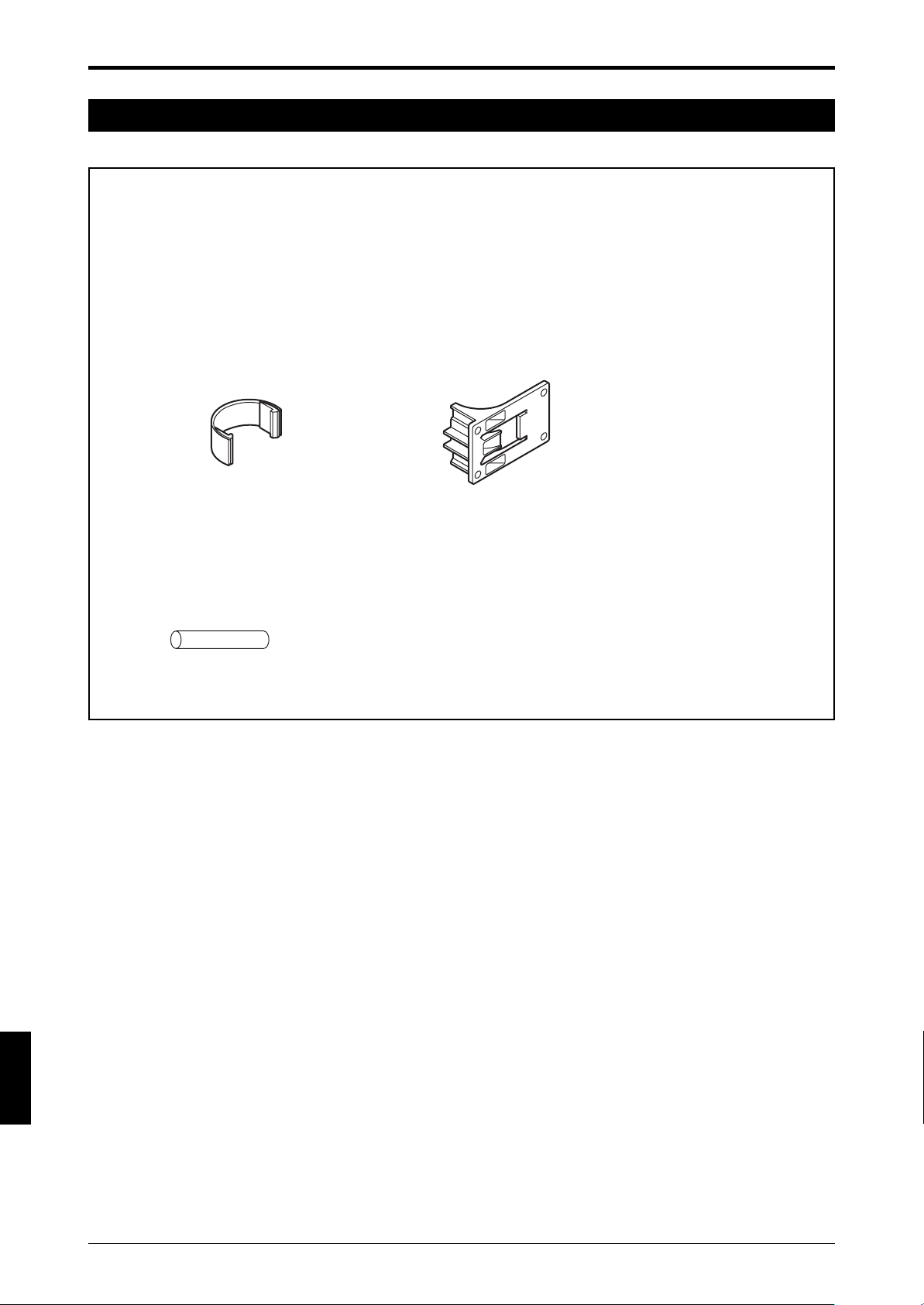
7. Package Contents
Confirm that the package includes the main unit and the following accessories.
■ Accessories
• Intermediate support bracket for installation
*Two pieces of supports are supplied with models SL-C72F through SL-C96F. Four pieces of supports
are supplied with models SL-C104F through SL-C128F.
*Two pieces of supports are supplied with models SL-C36H through SL-C48H. Four pieces of
supports are supplied with models SL-C52H through SL-C64H.
*Two pieces of supports are supplied with models SL-C18L through SL-C24L. Four pieces of supports
are supplied with models SL-C26L through SL-C32L.
Intermediate support bracket A Intermediate support bracket B
*Two connectors are also available grouped as a set (OP-42373).
* It is not possible to install the SL-C only by using the intermediate support brackets that come with
models SL-C72F through SL-C128F, SL-C36H through SL-C64H, SL-C18L through SL-C32L. Use
optional mounting brackets along with Intermediate support brackets.
ENGLISH
English
• One test piece (Diameter 14 mm (0.55") for SL-C **F, 25 mm (0.98") for SL-C**H)
* Optional test piece (diameter 45 mm (1.77") should be obtained for use of models SL-C08L through
SL-C32L.
• Instruction manual (this document) 1 copy
vii
Page 9
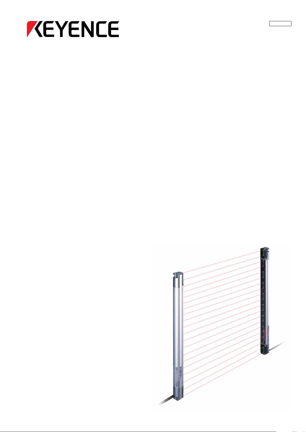
Chapter 1 Overview and Specifications
1 Overview and Specifications
1-1 Component Names and Units
This section describes each part of the SL-C Series and optional units.
For component locations and appearances, ➮
In this manual, "SL-C Series" means all of the models of SL-C. "SL-C**F" means only the models that have
the detection capability of 14 mm (0.55"). "SL-C**H" means only the models that have the detection
capability of 25 mm (0.98"), while "SL-C**L" means those that have the detection capability of 45 mm (1.77").
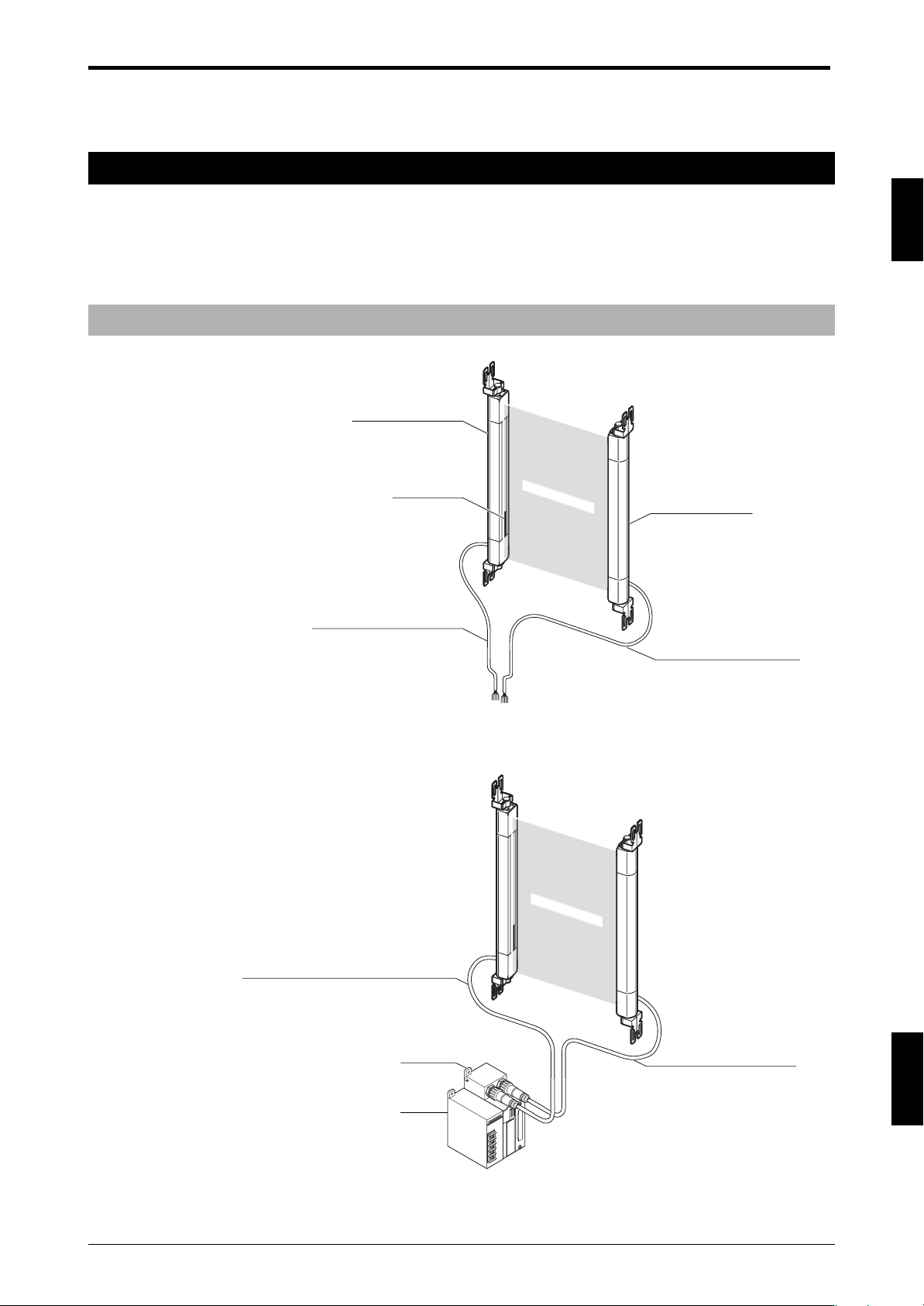
1-1-1 Main System and Cables
When using the SL-C stand-alone
T: Tr ansmitter
R: Receiver
SL-C Series Transmitter
see the “1-4 Dimensional Drawings” (page 1-5).
1
Status indicator
(on both sides)
SL-P7N/P (7 m (22.97 ft.)) cable
for transmitter (gray)
Detection zone
SL-C Series Receiver
SL-P7N/P (7 m (22.97 ft.)) cable
for receiver (black)
When combining the SL-C with a controller
SL-C Series + SL-U2 (Dedicated power supply unit) + SL-R11 (Intelligent safety relay unit)
Detection zone
SL-PC5P (5 m (16.4 ft.)) cable for transmitter (gray)
* 10 m(32.81
ft.
) SL-PC10P cable
SL-R11
SL-U2
SL-PC5P (5 m(16.4 ft.)) cable
for receiver (black)
* 10 m(32.81
SL-U2: The UL certified or recommended dedicated power supply unit
SL-R11:The safety relay is built-in. This is connected to the SL-C by a special connector.
ft.
) SL-PC10P cable
ENGLISH
1-1
Page 10
Chapter 1 Overview and Specifications
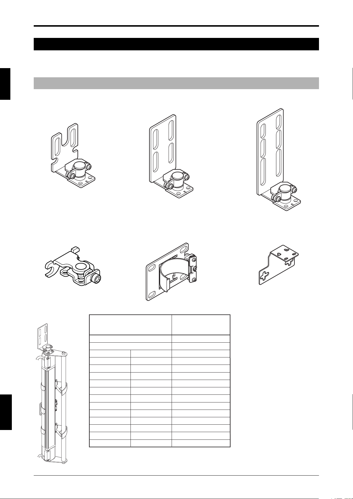
1-2 Mounting Brackets and Cables
This section offers an explanation of safety light curtain mounting brackets and cables. Mounting brackets
and cables are optional equipment for the SL-C.
1
1-2-1 Mounting Brackets
Normal mounting bracket A Normal mounting bracket B Normal mounting bracket C
OP-42347 (1 set of 2 brackets) OP-42348 (1 set of 2 brackets) OP-42349 (1 set of 2 brackets)
Includes 6 M3 screws (R=7). Includes 6 M3 screws (R=7). Includes 6 M3 screws (R=7).
Thin type mounting bracket E-to-E mounting bracket L-shaped mounting bracket
OP-51698 OP-42370 (1 set of 2 brackets) OP-42371 (1 set of 2 brackets)
ENGLISH
English
Includes 3 M3 screws Includes 6 M3 flathead screws
(R=7). (small head) (R=5).
Protection bar
SL-C Series Model
SL-C08H
SL-C12H
SL-C16H
SL-C20H
SL-C24H
SL-C28H
SL-C32H
SL-C36H
SL-C40H
SL-C44H
SL-C48H
SL-C52H
SL-C56H
SL-C60H
SL-C64H
SL-C08L
SL-C10L
SL-C12L
SL-C14L
SL-C16L
SL-C18L
SL-C20L
SL-C22L
SL-C24L
SL-C26L
SL-C28L
SL-C30L
SL-C32L
Applicable Model
of protection bar
to SL-C Series
OP-42350
OP-42351
OP-42352
OP-42353
OP-42354
OP-42355
OP-42356
OP-42357
OP-42358
OP-42359
OP-42360
OP-42361
OP-42362
OP-42363
OP-42364
* The protection bar cannot be used combined with the SL-C**F
and the thin type mounting bracket (OP-51698).
1-2
Page 11
1-2-2 Cables
SL-C plug - bare wires SL-P7N (NPN Type 7 m (22.97 ft.))
SL-P15N (NPN Type 15 m (49.21 ft.))
SL-P7P (PNP Type 7 m (22.97 ft.))
ø6
34
(1.34")
SL-C plug - M12 connector SL-PC5N (NPN 5 m (16.4 ft.))
SL-PC5P (PNP 5 m (16.4 ft.))
SL-PC10P (PNP 10 m (32.81 ft.))
(Transmitter/receiver set)
Chapter 1 Overview and Specifications
1
ø6
(Transmitter/receiver set)
47 (1.85")
M12 connector - M12 connector SL-CC10NT (NPN 10 m (32.81 ft.) Transmitter),
SL-CC10NR (NPN 10 m (32.81 ft.) Receiver),
SL-CC10PT (PNP 10 m (32.81 ft.) Transmitter),
SL-CC10PR (PNP 10 m (32.81 ft.) Receiver)
41.5 (1.63")
ø14
ø6
M12 connector-bare wires SL-C5N (NPN 5 m (16.4 ft.))
SL-C5P (PNP 5 m (16.4 ft.))
(Transmitter/receiver set)
ø6
ø14
Series connection cable SL-S0 (0.08 m (3.14"))
SL-S1 (0.15 m (5.91"))
SL-S2 (0.5 m (1.64 ft.))
SL-S3 (3 m (9.84 ft.))
SL-S4 (1 m (3.28 ft.))
SL-S10 (10 m (32.79 ft.))
(Transmitter/receiver set)
ø6
ENGLISH
1-3
Page 12
1
Chapter 1 Overview and Specifications
1-3 Specifications
Specifications (Detection capability of 14 mm (0.55") diameter type)
Model
No. of beam axes
Detection capability
Beam Axis Pitch/Lens Diameter
Detection zone
Protection zone
Current
consumption
Weight
Transmitter
Receiver
Transmitter
Receiver
SL-C16F
150 mm (5.90")
174 mm (6.85")
61 mA
66 mA
Approx. 180 g
Approx. 195 g
16
SL-C24F
230 mm (9.05")
254 mm (10.00")
67 mA
69 mA
Approx. 230 g
Approx. 255 g
SL-C32F
24
ø14 mm (0.55") (when the blanking function is not used)
310 mm (12.20")
334 mm (13.15")
73 mA
73 mA
Approx. 285 g
Approx. 310 g
SL-C40F
32
10 mm (0.39") / ø4 mm (0.15")
390 mm (15.35")
414 mm (16.30")
79 mA
76 mA
Approx. 335 g
Approx. 370 g
40
SL-C48F
48
470 mm (18.50")
494 mm (19.45")
85 mA
80 mA
Approx. 395 g
Approx. 425 g
SL-C56F
550 mm (21.65")
574 mm (22.60")
91 mA
83 mA
Approx. 440 g
Approx. 480 g
SL-C64F
56
630 mm (24.80")
654 mm (25.75")
97 mA
87 mA
Approx. 490 g
Approx. 540 g
64
SL-C72F
72
710 mm (27.95")
734 mm (28.90")
103 mA
90 mA
Approx. 540 g
Approx. 595 g
Model
No. of beam axes
Detection capability
Beam Axis Pitch/Lens Diameter
Detection zone
Protection zone
Current
consumption
Weight
Transmitter
Receiver
Transmitter
Receiver
SL-C80F
790 mm (31.10")
814 mm (32.05")
109 mA
94 mA
Approx. 590 g
Approx. 655 g
80
SL-C88F
ø14 mm (0.55") (when the blanking function is not used)
870 mm (34.25")
894 mm (35.20")
115 mA
97 mA
Approx. 645 g
Approx. 710 g
88
SL-C96F
10 mm (0.39") / ø4 mm (0.15")
950 mm (37.40")
974 mm (38.35")
121 mA
100 mA
Approx. 695 g
Approx. 765 g
SL-C104F
96
1030 mm (40.55")
1054 mm (41.50")
Approx. 745 g
Approx. 825 g
104
127 mA
104 mA
SL-C112F
1110 mm (43.70")
1134 mm (46.65")
133 mA
107 mA
Approx. 800 g
Approx. 880 g
112
Specifications (Detection capability of 25 mm (0.98") diameter type)
Model
No. of beam axes
Detection capability
Beam Axis Pitch/Lens Diameter
Detection zone
Protection zone
Current
consumption
Weight
Transmitter
Receiver
Transmitter
Receiver
SL-C08H
140 mm (5.51")
185 mm (7.28")
55 mA
67 mA
Approx. 165 g
Approx. 180 g
SL-C12H
8
220 mm (8.66")
265 mm (10.43")
Approx. 210 g
Approx. 230 g
SL-C16H
12
ø25 mm (0.98") (when the blanking function is not used)
300 mm (11.81")
345 mm (13.58")
58 mA
69 mA
61 mA
71 mA
Approx. 255 g
Approx. 280 g
SL-C20H
16
20 mm (0.79") / ø5 mm (0.19")
380 mm (14.96")
425 mm (16.73")
62 mA
73 mA
Approx. 300 g
Approx. 330 g
SL-C24H
20
460 mm (18.11")
505 mm (19.88")
68 mA
76 mA
Approx. 345 g
Approx. 380 g
SL-C120F
1190 mm (46.85")
1214 mm (47.80")
Approx. 850 g
Approx. 940 g
SL-C28H
24
540 mm (21.26")
585 mm (23.03")
Approx. 390 g
Approx. 430 g
120
139 mA
111 mA
28
71 mA
78 mA
SL-C128F
128
1270 mm (50.00")
1294 mm (50.94")
145 mA
114 mA
Approx. 900 g
Approx. 995 g
SL-C32H
620 mm (24.41")
665 mm (26.18")
74 mA
81 mA
Approx. 435 g
Approx. 480 g
SL-C36H
32
700 mm (27.56")
745mm (29.33")
77 mA
83 mA
Approx. 480 g
Approx. 530 g
36
ENGLISH
English
Model
No. of beam axes
Detection capability
Beam Axis Pitch/Lens Diameter
Detection zone
Protection zone
Current
consumption
Weight
Transmitter
Receiver
Transmitter
Receiver
1-4
SL-C40H
780 mm (30.71")
825 mm (32.48")
81 mA
86 mA
Approx. 525 g
Approx. 575 g
SL-C44H
40
ø25 mm (0.98") (when the blanking function is not used)
860 mm (33.86")
905 mm (35.63")
84 mA
88 mA
Approx. 570 g
Approx. 625 g
44
SL-C48H
20 mm (0.79") / ø5 mm (0.19")
940mm (37.01")
985 mm (38.78")
87 mA
90 mA
Approx. 615 g
Approx. 675 g
SL-C52H
48
1020 mm (40.16")
1065 mm (41.92")
Approx. 660 g
Approx. 725 g
52
91 mA
93 mA
SL-C56H
1100 mm (43.31")
1145 mm (45.08")
94 mA
95 mA
Approx. 705 g
Approx. 775 g
SL-C60H
56
1180 mm (46.46")
1225 mm (48.23")
Approx. 750 g
Approx. 825 g
60
97 mA
97 mA
SL-C64H
64
1260 mm (49.61")
1305 mm (51.38")
100 mA
100 mA
Approx. 860 g
Approx. 945 g
Page 13

Chapter 1 Overview and Specifications
Specifications (Detection capability of 45 mm (1.77") diameter type)
Model
No. of beam axes
Detection capability
Beam Axis Pitch/Lens Diameter
Detection zone
Protection zone
Current
consumption
Weight
Transmitter
Receiver
Transmitter
Receiver
SL-C08L
280 mm (11.02")
365 mm (14.37")
55 mA
67 mA
Approx. 255 g
Approx. 280 g
SL-C10L
8
360 mm (14.17")
445 mm (17.52")
Approx. 300 g
Approx. 330 g
10
57 mA
68 mA
SL-C12L
12
440 mm (17.32")
525 mm (20.67")
58 mA
69 mA
Approx. 345 g
Approx. 380 g
SL-C14L
14
ø45 mm (1.77")
40 mm (1.57") / ø5 mm (0.19")
520 mm (20.47")
605 mm (23.82")
60 mA
70 mA
Approx. 390 g
Approx. 430 g
SL-C16L
16
600 mm (23.62")
685 mm (26.97")
61 mA
71 mA
Approx. 435 g
Approx. 480 g
SL-C18L
680mm (26.77")
765 mm (30.12")
62 mA
72 mA
Approx. 480 g
Approx. 530 g
SL-C20L
18
760 mm (29.92")
845 mm (33.27")
62 mA
73 mA
Approx. 525 g
Approx. 575 g
20
SL-C22L
22
1
840 mm (33.07")
925 mm (36.42")
65 mA
75 mA
Approx. 570 g
Approx. 625 g
Model
No. of beam axes
Detection capability
Beam Axis Pitch/Lens Diameter
Detection zone
Protection zone
Current
consumption
Weight
The blanking and muting functions of SL-R12EX cannot be used with SL-C**L (detection
capability of 45 mm diameter type).
Transmitter
Receiver
Transmitter
Receiver
SL-C24L
920 mm (36.22")
1005 mm (39.57")
68 mA
76 mA
Approx. 615 g
Approx. 675 g
SL-C26L
24
1000 mm (39.37")
1085 mm (42.72")
Approx. 660 g
Approx. 725 g
SL-C28L
26
40 mm (1.57") / ø5 mm (0.19")
70 mA
77 mA
28
ø45 mm (1.77")
1080 mm (42.52")
1165 mm (45.87")
71 mA
78 mA
Approx. 705 g
Approx. 775 g
SL-C30L
30
1160 mm (45.67")
1245 mm (49.02")
73 mA
80 mA
Approx. 750 g
Approx. 825 g
SL-C32L
1240 mm (48.82")
1325 mm (53.17")
74 mA
81 mA
Approx. 860 g
Approx. 945 g
32
1-5
ENGLISH
Page 14

1
Chapter 1 Overview and Specifications
Common specifications
Model
SL-C**F Operating distance
SL-C**H/SL-C**L Operating distance
Effective Aperture Angle
Max. ±2.5° (When operating distance is 3 m (9.84 ft.) or more)
Response time
Light source
Operation form
Rating
Power voltage
Output type
Turns on when light is received from all light beams (except when the blanking function is used)
24V DC ±10% (Ripple P-P 10% or less)
2 outputs each for PNP and NPN, Can be changed using the connector cable
Max. load current
OSSD
Output
OFF-state voltage
Leakage current
Max. capacitive load
2.5 V (with a cable length of 7 m (22.97 ft.))
0.47 µF (with a load resistance of 100 Ω)
Load wiring resistance
Protective structure
Environmental
specifications
Ambient temperature
Storage ambient temperature
Relative humidity
Storage ambient humidity
Ambient light
Vibration
Shock
35 % to 85 %RH (No condensation)
White incandescent lamp: 5,000rx or less Sunlight: 20,000rx or less
10 to 55 Hz, 0.7 mm compound amplitude, 20 sweeps each in X, Y, and Z directions
100 m/s2 (Approx. 10G) 16ms pulse, in X, Y, Z directions 1,000 times each axis
Main unit case
Material
Upper case/Lower case
Overlay
EMC
Approved
standards
*1 OFF ➝ ON return time is 125 ms.
*2 Note the derating illustrated in the graph to the right when using PNP output.
*3 Includes when the SL-C Series power supply is OFF or when there is a disconnection in the power
supply line.
*4 In order to guarantee the proper operation of the SL-C safety circuit, the wiring resistance (excluding
dedicated cable wiring resistance) of the cabling connected to the hardware to which the OSSD output
and OSSD input are connected must be 2.5 Ω or less. For NPN output type cable, do not let wiring
resistance exceed a maximum of 1.0 Ω when the cable length is 15 m (49.21 ft.) or greater and the
load current is 200 mA or higher.
Safety
EMS
EMI
SL-C Series
0.1 to 7 m
0.3 to 9 m
1
15 ms*
Infrared LED (850 nm)
300 mA*
2
Max. 100 µA*
Max. 2.5 Ω*
4
IP65 (IEC60529)
-10°C to 55°C (No frost)
-10°C to 60°C (No frost)
35 % to 95 %
Aluminum
Zinc die-cast
Polycarbonate
UL61496-1
FCC Part15 Class A
UL61496-1 (
UL61496-2 (
type
type
UL508
4 ESPE)
4 AOPD)
3
(mA)
300
200
100
0
10 20 30 40 50 (°C)
ENGLISH
English
1-6
Page 15
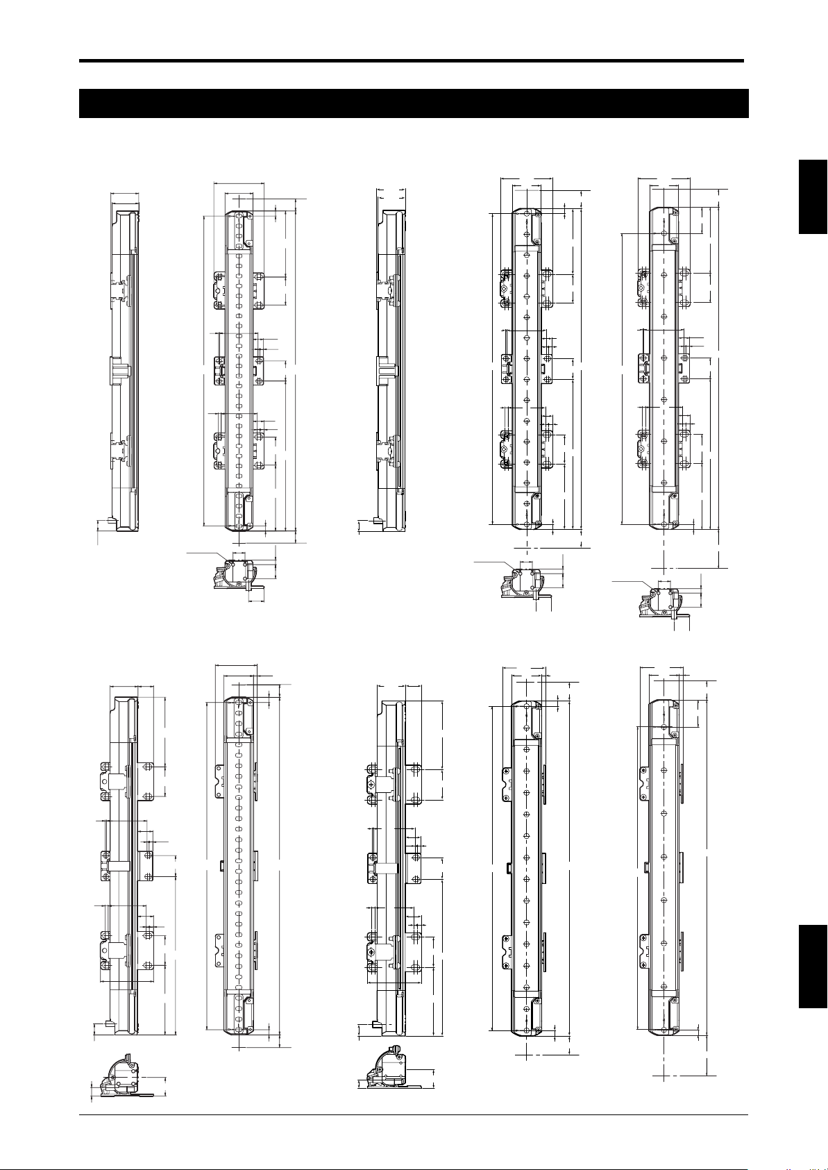
1-4 Dimensional Drawings
Chapter 1 Overview and Specifications
With the E-to-E mounting bracket (OP-42370) installed
10.6
27.9
26.4
B
3-M3
Depth:4.5
1 38.5
3 36
50.4
28
7
5
D
28
10.5
2
3.5
A
20
11
3
4
28
C
D
5
7
4.5
12
14
15.5
10.6
27.9
26.4
SL-C**HSL-C**F SL-C**L
50.4
28
17.5
5
D
28
38.5
B
3-M3
Depth:4.5
1
3
10.5
2
3.5
A
20
36
11
3
4
28
C
D
5
17.5
4.5
12
14
15.5
3-M3
Depth:4.5
(
Unit: mm
50.4
28
38.5
1
B
36
3
12
15.5
)
17.5
25
D
28
10.5
3.5
A
20
11
3
4
28
C
D
5
37.5
4.5
14
1
3 36
10.6
39.7
14.626.4
D
28
38.51
14.5
2
3.5
20
15
3
4
28
C
50.4
D
28 3.5
7
5
1
B
A
3
5
7
10.6
38.5
26.4
36
14.6
14.5
2
3
50.4
D
28
3.5
20
15
4
28
C
D
39.7
3.5
28
17.5
5
B
A
5
17.5
B
39.7
28 3.5
17.5
25
A
ENGLISH
5
37.5
SL-C**HSL-C**F SL-C**L
8
17.5
8
17.5
1-7
Page 16
Chapter 1 Overview and Specifications
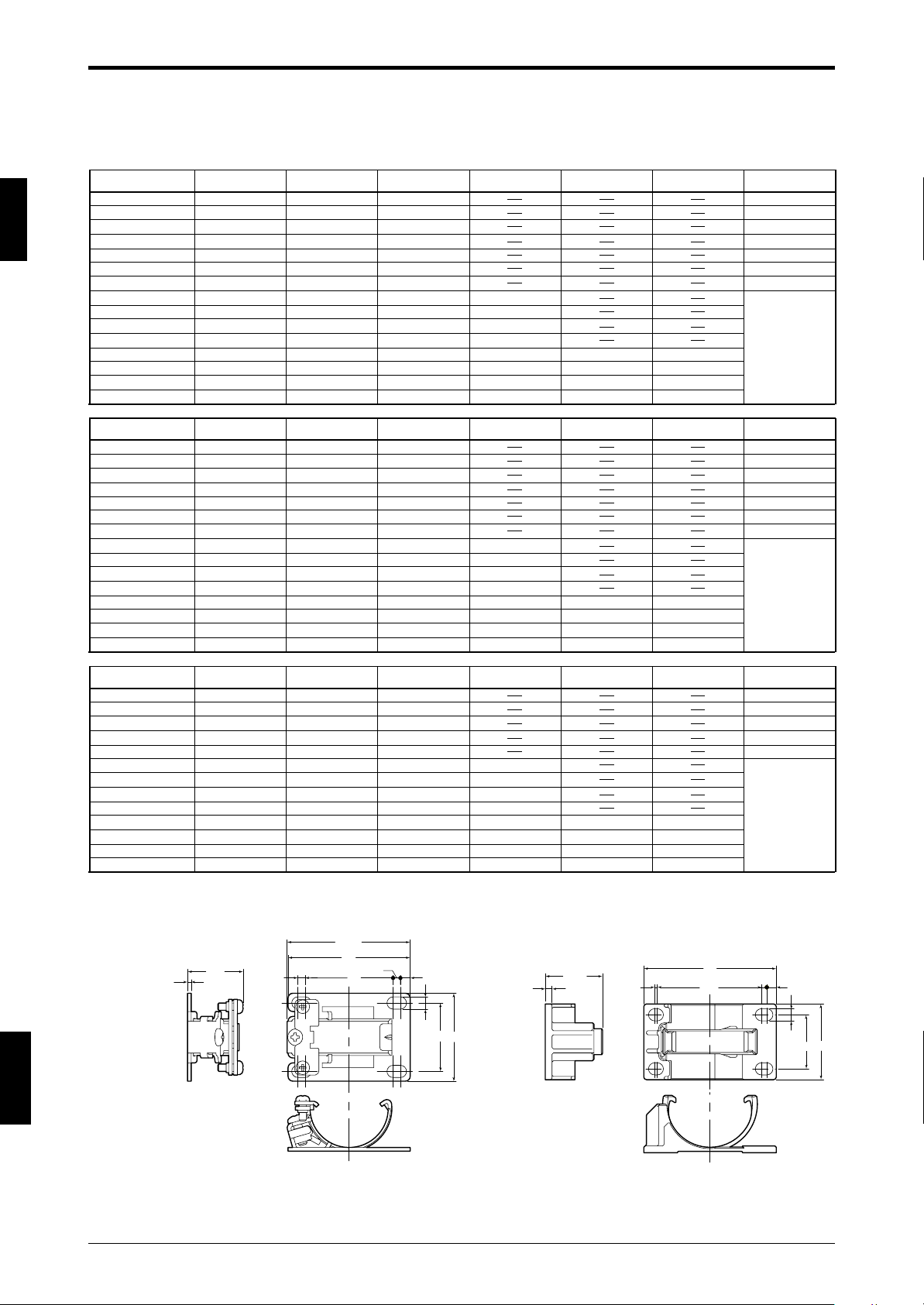
1
Dimensions by model
Model
SL-C16F
SL-C24F
SL-C32F
SL-C40F
SL-C48F
SL-C56F
SL-C64F
SL-C72F
SL-C80F
SL-C88F
SL-C96F
SL-C104F
SL-C112F
SL-C120F
SL-C128F
Model
SL-C08H
SL-C12H
SL-C16H
SL-C20H
SL-C24H
SL-C28H
SL-C32H
SL-C36H
SL-C40H
SL-C44H
SL-C48H
SL-C52H
SL-C56H
SL-C60H
SL-C64H
Model
SL-C08L
SL-C10L
SL-C12L
SL-C14L
SL-C16L
SL-C18L
SL-C20L
SL-C22L
SL-C24L
SL-C26L
SL-C28L
SL-C30L
SL-C32L
* If using the normal mounting brackets A, B, C, or the L-shaped mounting bracket for installing the model that has the sensor length 710 mm (27.95") or more, use of two intermediate support
brackets is required. For such installation, attach intermediate support brackets at dimensional positions C1 and C2. For other installations, attach one intermediate support bracket at dimensional
position C.
No. of beam axes
16
24
32
40
48
56
64
72
80
88
96
104
112
120
128
No. of beam axes
8
12
16
20
24
28
32
36
40
44
48
52
56
60
64
No. of beam axes
8
10
12
14
16
18
20
22
24
26
28
30
32
Sensor length A
160 (6.30")
240 (9.45")
320 (12.60")
400 (15.75")
480 (18.90")
560 (22.05")
640 (25.20")
720 (28.35")
800 (31.50")
880 (34.65")
960 (37.80")
1040 (40.94")
1120 (44.09")
1200 (47.24")
1280 (50.39")
Sensor length A
150 (5.91")
230 (9.06")
310 (12.20")
390 (15.35")
470 (18.50")
550 (21.65")
630 (24.80")
710 (27.95")
790 (31.10")
870 (34.25")
950 (37.40")
1030 (40.55")
1110 (43.70")
1190 (46.85")
1270 (50.00")
Sensor length A
310 (12.20")
390 (15.35")
470 (18.50")
550 (21.65")
630 (24.80")
710 (27.95")
790 (31.10")
870 (34.25")
950 (37.40")
1030 (40.55")
1110 (43.70")
1190 (46.85")
1270 (50.00")
Detection zone B
150 (5.91")
230 (9.06")
310 (12.20")
390 (15.35")
470 (18.50")
550 (21.65")
630 (24.80")
710 (27.95")
790 (31.10")
870 (34.25")
950 (37.40")
1030 (40.55")
1110 (43.70")
1190 (46.85")
1270 (50.00")
Detection zone B
140 (5.51")
220 (6.66")
300 (11.81")
380 (14.96")
460 (18.11")
540 (21.56")
620 (24.41")
700 (27.56")
780 (30.71")
860 (33.86")
940 (37.01")
1020 (40.16")
1100 (43.31")
1180 (46.46")
1260 (49.61")
Detection zone B
280 (11.02")
360 (14.17")
440 (17.32")
520 (20.47")
600 (23.62")
680 (26.77")
760 (29.92")
840 (33.07")
920 (36.22")
1000 (39.37")
1080 (42.52")
1160 (45.67")
1240 (48.82")
Intermediate support
bracket position C*
350±80 (13.78"±3.15")
390±80 (15.35"±3.15")
430±80 (16.93"±3.15")
470±80 (18.50"±3.15")
510±80 (20.08"±3.15")
550±80 (21.65"±3.15")
590±80 (23.23"±3.15")
630±80 (24.80"±3.15")
Intermediate support
bracket position C*
345±80 (13.58"±3.15")
385±80 (15.16"±3.15")
425±80 (16.73"±3.15")
465±80 (18.31"±3.15")
505±80 (19.88"±3.15")
545±80 (21.46"±3.15")
585±80 (23.03"±3.15")
625±80 (24.61"±3.15")
Intermediate support
bracket position C*
345±80 (13.58"±3.15")
385±80 (15.16"±3.15")
425±80 (16.73"±3.15")
465±80 (18.31"±3.15")
505±80 (19.88"±3.15")
545±80 (21.46"±3.15")
585±80 (23.03"±3.15")
625±80 (24.61"±3.15")
Intermediate support
bracket position C1*
337±80 (13.27"±3.15")
363±80 (14.29"±3.15")
390±80 (15.35"±3.15")
417±80 (16.42"±3.15")
Intermediate support
bracket position C1*
333±80 (13.11"±3.15")
360±80 (14.17"±3.15")
387±80 (15.24"±3.15")
413±80 (16.26"±3.15")
Intermediate support
bracket position C1*
333±80 (13.11"±3.15")
360±80 (14.17"±3.15")
387±80 (15.24"±3.15")
413±80 (16.26"±3.15")
Intermediate support
bracket position C2*
683±80 (26.89"±3.15")
737±80 (29.02"±3.15")
790±80 (31.10"±3.15")
843±80 (33.19"±3.15")
Intermediate support
bracket position C2*
677±80 (26.65"±3.15")
730±80 (28.74"±3.15")
783±80 (30.83"±3.15")
837±80 (32.95"±3.15")
Intermediate support
bracket position C2*
677±80 (26.65"±3.15")
730±80 (28.74"±3.15")
783±80 (30.83"±3.15")
837±80 (32.95"±3.15")
D
45 (1.77")
45 to 66 (1.77" to 2.60")
45 to 93 (1.77" to 3.66")
45 to 119 (1.77" to 4.69")
45 to 146 (1.77" to 5.75")
45 to 173 (1.77" to 6.81")
45 to 199 (1.77" to 7.83")
45 to 200 (1.77" to 7.87")
D
43 (1.69")
43 to 63 (1.69" to 2.48")
43 to 89 (1.69" to 3.50")
43 to 116 (1.69" to 4.57")
43 to 143 (1.69" to 5.63")
43 to 169 (1.69" to 6.65")
43 to 196 (1.69" to 7.72")
43 to 197 (1.69" to 7.76")
D
43 to 89
(1.69" to 3.50")
43 to 116 (1.69" to 4.57")
43 to 143 (1.69" to 5.63")
43 to 169 (1.69" to 6.65")
43 to 196 (1.69" to 7.72")
43 to 197 (1.69" to 7.76")
ENGLISH
English
E-to-E mounting bracket
(
OP-42370
)
(24)
1.5
1-8
(50.4)
50
3 36
Intermediate support brackets (OP-42373
3
4
5
28
36
(21.2)
2.5
1
38.5
49
2
4.5
)
3.5
28
20
Page 17
Chapter 1 Overview and Specifications
21
2
27.5
29
8
19
22
7.5
5
27
(41.3)
21
27.5
18
29
7.5
7.5
14.5
(62.5)
6
19
2
2
6
19
7.8
8
8
13(0.51"
)
8
17
21
18
29
(82.3)
10.6
12
(21.8)
(14.3)
29
5
16.5
22
10.6
16.5
12
(21.8(0.86"))
5
5(0.2")
(14.3)
22
10.6
6
19
29
14.5
7.5
14.5
(18.5)
5
5
14.5
7.5
14.5
6
19
29
(18.5)
10.6
10.6
6
19
29
17
8
13
8
8
(20.5)
5
5
17
8
13
8
8
7.8
6
19
29
10.6
(20.5)
Normal mounting bracket A,
inward-facing (OP-42347)
With Normal mounting bracket A installed
Normal mounting bracket B (OP-42348)
With Normal mounting bracket B installed
Normal mounting bracket C (OP-42349)
With Normal mounting bracket C installed
27.9
27.9
27.9
17.5
17.5
7.5
7.5
17.5
7.8
5
8
5
8
5
8
11.5
5
(
0.2"
)
(
0.2"
)
(
0.2"
)
(
0.2"
)
(
0.42"
)
(
0.65"
)(
0.65"
)
(
0.31"
)
(
0.87"
)
(
0.87"
)
(
0.69"
)
(
0.56"
)
(
1.14"
)
(
1.08"
)(
1.14"
)
(
0.83"
)
(
0.45"
)
(
0.87"
)
(
1.08"
)
27.5
(
1.08"
)
(
1.14"
)
(
2.46"
)
(
0.42"
)
(
1.1"
)
(
0.2"
)
(
0.3"
)
(
0.3"
)
(
0.24"
)
(
0.24"
)
(
0.24"
)
(
0.31"
)
(
0.2"
)
(
0.2"
)
(
0.81"
)
(
0.67"
)
(
0.31"
)
(
0.31"
)
(
0.31"
)
(
0.31"
)
(
0.51"
)
(
0.67"
)
(
0.69"
)
(
0.2"
)
(
0.31"
)
(
0.31"
)
(
0.31"
)
(
0.31"
)
(
0.51"
)
(
0.2"
)
(
0.24"
)
(
0.42"
)
(
0.42"
)
(
0.81"
)
(
0.72"
)
(
0.31"
)
(
0.75"
)
(
1.14"
)
(
0.75"
)
(
1.14"
)
(
0.75"
)
(
1.14"
)
(
0.75"
)
(
1.14"
)
(
0.72"
)
(
0.57"
)
(
0.57"
)
(
0.3"
)
(
0.3"
)
(
0.57"
)
(
0.2"
)
(
0.69"
)
(
0.57"
)
(
0.75"
)
(
0.57"
)
14.5 (0.57"
)
(
0.3"
)
(
0.3"
)
(
0.08")(0.24"
)
(
0.08")(0.24"
)
(
0.75"
)
(
0.31"
)
(
0.31"
)
(
0.31"
)
(
0.31"
)
(
0.67"
)
(
3.24"
)
(
0.42"
)
(
1.1"
)
(
0.83"
)
(
0.83"
)
(
0.71"
)
(
1.14"
)
(
0.71"
)
(
0.75"
)
(
0.08"
)
(
0.2"
)
(
1.63"
)
(
1.06"
)
12 (0.47"
)
(
0.31"
)(
0.3"
)
(
0.42"
)
(
1.1"
)
(
0.86"
)
(
0.47"
)(
0.47"
)
(
0.56"
)
(
0.86"
)
21
27.5
18
29
5
27
7.5
12
(46.5)
2
8
19
22
11.5
(19.5)
27
5
7.5
12
6
19
29
10.6
6
19
(19.5)
10.6
12
7.5
27
5
Normal mounting bracket A,
outward-facing (OP-42347)
With Normal mounting bracket A installed
27.9
17.5
5
8
(
1.08"
)
(
0.83"
)
(
0.08"
)
(
1.14"
)
(
0.71"
)
(
0.31"
)
(
0.75"
)
(
0.87"
)
(
0.2"
)
(
1.83"
)
(
0.42"
)
(
0.42"
)
(
1.1"
)
(
0.24"
)
(
0.2"
)
(
0.77"
)
(
0.77"
)
(
1.06"
)
(
1.06"
)
(
0.3"
)
(
0.3"
)
(
0.2"
)
(
0.31"
)
(
0.24"
)
(
0.75"
)
(
0.75"
)
(
1.14"
)
29
(
1.14"
)
(
0.47"
)
(
0.47"
)
(
1.06"
)
(
0.45"
)
(
0.3"
)
(
0.47"
)
(
0.2"
)
(
0.69"
)
1
ENGLISH
1-9
Page 18

Chapter 1 Overview and Specifications
1
Thin type mounting backet (OP-51698)
(32.4)
2
*When installing the normal
mounting bracket on the
machine, use the M4
screws shorter than 3.8
(0.15") mm.
28
1.1
22
5
(6.8)
(10.2)
L-shaped mounting bracket
(OP-42371)
60(2.36")
52(2.05")
4(0.16")
14
(0.55")
(0.07")
12
(0.47")
R1.8
44(1.73")
30(1.18")
23(0.91")
28(1.1")
16
(0.63")
12
(0.47")
20(0.79")
t=1.0
8(0.31")
40(1.57")
26
(1.02")
5.2
(0.2")
5.2
(0.2")
27.5 (1.08")
With thin mounting bracket installed
1.1
5
22
28
5
(6.8)
10.6
10.6
5
(32.4)
With the L-shaped mounting bracket installed
(When installed on the SL-C08H through SL-C64H)
20
(0.79")
28
5(0.2")
16
(0.63")
(1.1")
30(1.18")
44(1.73")
52(2.05")
60(2.36")
14
(0.55")
(1.02")
8(0.31")
26
16
(0.63")
28
(1.1")
9(0.35")
25
(0.98")
8
(0.31")
1.1
60(2.36")
52(2.05")
44(1.73")
30(1.18")
8
5
18
(0.71")
(30.9)
5
22
(6.8)
20
(0.79")
31.5
17.5
(0.69")
17.5
ENGLISH
English
SL-U2
35
2(0.08")
(1.38")
-ø4.2
11(0.43")
(0.67")
24
(0.94")
(3.94")
11(0.43")
SL-R11(E)
3.5
(0.14")
49.8
(1.96")
(1.41")
35.9
(102.3)(4.03")
83.8
(3.3")
100
(112)(4.41")
(96.6)
(3.8")
3.5
(0.14")
2(0.08")
-ø4.2
(0.67")
124
(4.88")
25.8
(1.02")
35.9
(1.41")
(1.89")
(4.37")
48
23
(0.91")
111
23(0.91")
135
(5.31")
1-10
37
(1.46")
Page 19

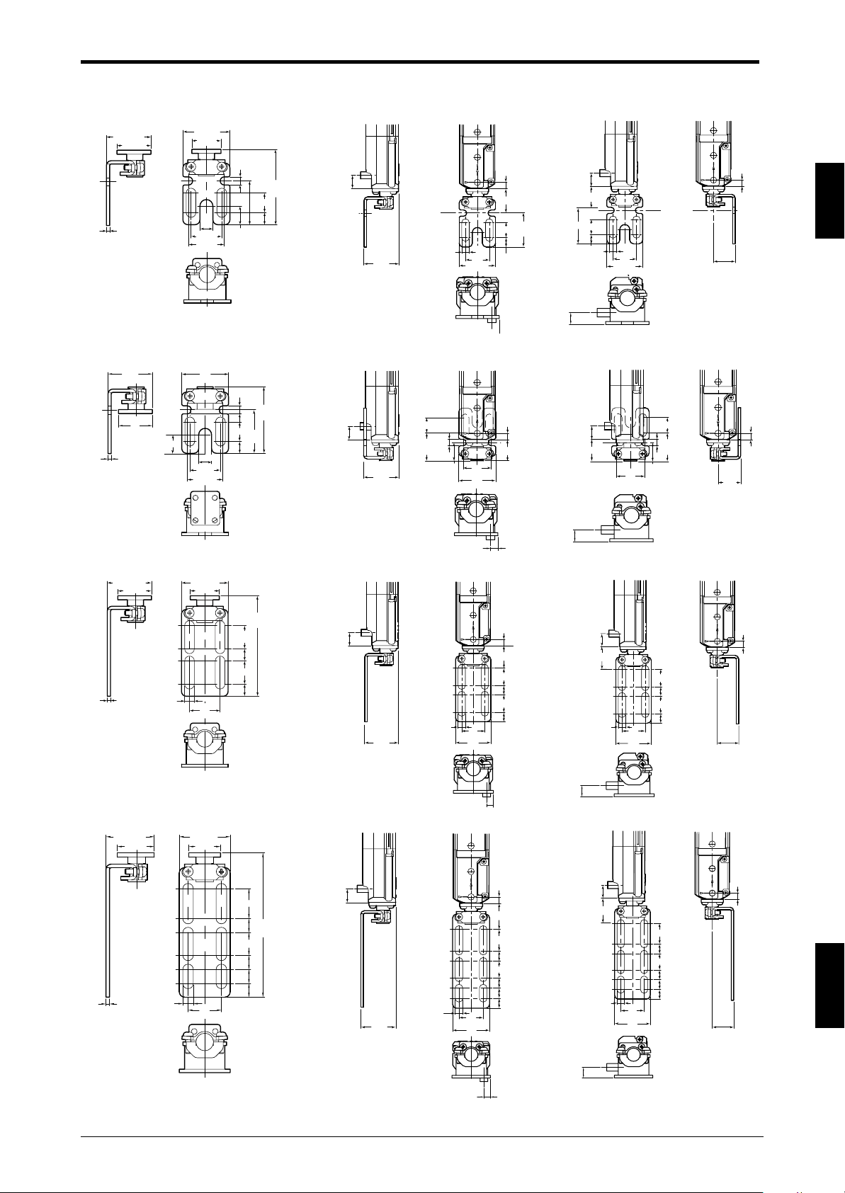
Chapter 1 Overview and Specifications
With the protection bar installed
SL-C**H SL-C**L SL-C**H SL-C**L
M3 (R=7)
D
This installation uses M3
(r=7) screws in the
locations marked with .
60(2.36")
(59°)
Bracket A
M6 hexagonal bolt
(5mm (0.2") diagonal)
Bar
Bar
support
15
(0.59")
Intermediate
support bracket
C
B
15(0.59")
D
A
16(0.63")
With the
protection
59.5
(2.34")
(44°)
36
15
C
B
15
A
16
bar installed
59.5
(2.34")
(29°)
Example standard mounting bracket installation
15
(0.59")
C
15(0.59")
B
D
A
5
(1.91")
This installation uses M3
(r=10) screws in the
locations marked with .
(0.2")
(48.5)
60(2.36")
16(0.63")
(59°)
5
48.5
36
1
15
C
B
15
A
16
64
(2.52")
(1.81")
63.5(2.5")
Dimensions by model
Model
SL-C08H
SL-C12H
SL-C16H
SL-C20H
SL-C24H
SL-C28H
SL-C32H
SL-C36H
SL-C40H
SL-C44H
SL-C48H
SL-C52H
SL-C56H
SL-C60H
SL-C64H
Model
SL-C08L
SL-C10L
SL-C12L
SL-C14L
SL-C16L
SL-C18L
SL-C20L
SL-C22L
SL-C24L
SL-C26L
SL-C28L
SL-C30L
SL-C32L
No. of
beam axes
8
12
16
20
24
28
32
36
40
44
48
52
56
60
64
No. of
beam axes
8
10
12
14
16
18
20
22
24
26
28
30
32
bracket position A
(8.15")207±50(1.97")
(10.24")260±50(1.97")
(11.3")287±50(1.97")
(12.36")314±50(1.97")
(13.39")340±50(1.97")
(14.45")367±50(1.97")
(15.51")394±50(1.97")
(16.54")420±50(1.97")
(17.6")447±50(1.97")
bracket position A
(8.15")207±50(1.97")
(10.24")260±50(1.97")
(11.3")287±50(1.97")
(12.36")314±50(1.97")
(13.39")340±50(1.97")
(14.45")367±50(1.97")
(15.51")394±50(1.97")
(16.54")420±50(1.97")
(17.6")447±50(1.97")
64
(2.52")
46
Bar support
(9.21)234±50(1.97")
Bar support
(9.21)234±50(1.97")
64
(2.52")
45.5
(1.79")
63
(2.48")
Bar support
bracket position B
(13.78")350±50(1.97")
(15.87")403±50(1.97")
(17.99")457±50(1.97")
(20.08")510±50(1.97")
(22.17")563±50(1.97")
(24.29")617±50(1.97")
(26.38")670±50(1.97")
(28.46")723±50(1.97")
(30.59")777±50(1.97")
(32.68")830±50(1.97")
Bar support
bracket position B
(13.78")350±50(1.97")
(15.87")403±50(1.97")
(17.99")457±50(1.97")
(20.08")510±50(1.97")
(22.17")563±50(1.97")
(24.29")617±50(1.97")
(26.38")670±50(1.97")
(28.46")723±50(1.97")
(30.59")777±50(1.97")
(32.68")830±50(1.97")
45.5
(1.79")
63
(2.48")
Length C
172(6.67")
252(9.92")
332(13.07")
412(16.22")
492(19.37")
572(22.52")
652(25.67")
732(28.82")
812(31.97")
892(35.12")
972(38.27")
1052(41.42")
1132(44.57")
1212(47.72")
1292(50.87")
Length C
332(13.07")
412(16.22")
492(19.37")
572(22.52")
652(25.67")
732(28.82")
812(31.97")
892(35.12")
972(38.27")
1052(41.42")
1132(44.57")
1212(47.72")
1292(50.87") (24.88")632±50(1.97")
Intermediate support
bracket position D
(13.86")352±50(1.97")
(15.43")392±50(1.97")
(17.01")432±50(1.97")
(18.58")472±50(1.97")
(20.16")512±50(1.97")
(21.73")552±50(1.97")
(23.30")592±50(1.97")
(24.88")632±50(1.97")
Intermediate support
bracket position D
(13.86")352±50(1.97")
(15.43")392±50(1.97")
(17.01")432±50(1.97")
(18.58")472±50(1.97")
(20.16")512±50(1.97")
(21.73")552±50(1.97")
(23.30")592±50(1.97")
64
(2.52")
(1.81")
63.5(2.5")
46
ENGLISH
1-11
Page 20

1
Chapter 1 Overview and Specifications
1-5 Functions
1-5-1 Status Indicator
LOCKOUT
8
7
6
5
4
3
2
1
ON/OFF
FUNCTION
1. Lockout indicator (orange)
2. Bar LED (green / red)
3. Output status indicator (green / red)
4. Function indicator (orange)
1. Lockout indicator
If the SL-C control circuit detects an error, the SL-C goes to lockout condition and the status indicator
turns orange. At the same time, the OSSD output (or FSD output when the SL-R11 is connected to the
SL-C) is turned off and the machine stops.
2. Bar LEDs
Each transmitter and receiver has an 8-segment LED indicator that shows the SL-C operation status.
When the paths of all beam axes are clear of any obstruction in the normal state, all LEDs turn green.
When there is some blockage of the beam axes, some of the eight LEDs will turn red to indicate the
percentage of the total beam axes whose light beams are being received.
When receiver cannot get any light from transmitter in spite of no obstruction, the red LED at the bottom
flashes.
ENGLISH
English
3. Output status indicator
This indicates the OSSD output status (or the FSD output status if the SL-R11 is connected to the SL-C
Series). When the OSSD (or FSD) output is turned ON, the indicator lights green. When the OSSD (or
FSD) output is turned OFF, the indicator turns red.
Therefore, if the output status indicator is red, the OSSD (or FSD) output is turned OFF and the machine
has been stopped regardless of the functions being used.
4. Function indicator
The function indicator turns orange if each function supported by the SL-R12EX has been enabled. For
details, see the Instruction Manual for the SL-R12EX.
1-12
Page 21

Chapter 1 Overview and Specifications
1-5-2 Lockout Status Bar LED Indicator
If the SL-C Series goes into a lockout condition, the lockout indicators on all SL-C Series units connected in
series (➮see “Series connection”
part of the 8-segment bar LEDs in the SL-C begins to flash, and the operator can see in what part the
trouble occurred by checking the LED flashing status in the following table. For details, ➮
“Troubleshooting” (page 5-1).
(page 3-4)
for more information about in-series connection) turn ON. Also,
see Chapter 5
1
LOCKOUT
ON/OFF
FUNCTION
Orange Green Red
Orange: Control circuit anomaly
8
7
6
5
4
3
2
1
Green: OSSD (or FSD) output is ON
Red : OSSD (or FSD) output is OFF
Flashes orange when all functions have been enabled by SL-R12EX
Status Indicator
LEDs 1 - 8 all green:
stable, no obstructions.
LEDs 1 - 8 not all green:
unstable
obstructions
are present.
Lockout Condition Display
8 Flashing red :
7 Flashing red :
6 Flashing red :
5 Flashing red :
4 Flashing red :
3 Flashing red :
2 Flashing red :
1 Flashing red :
SL-R11 FSD error
OSSD error
Communications
error
Interfering light error
Transmitter / Receiver
beam axes misaligned
SL-R11(E) error
Receiver error
Transmitter error
1-5-3 Test Input
The test input stops light beam transmission from the transmitter using an external input.
The test input is used to see if the machine connected to the SL-C can stop within the prescribed time when
the OSSD (FSD when the SL-R11 is connected to the SL-C) turns off.
For example, when test input is triggered when the SL-C is in the normal state (when OSSD or FSD output is
on when all beam axes are clear of any obstruction), the OSSD or FSD is turned off and only one bar LED of
the SL-C flashes red. (Exception is when the fixed blanking function is used.)
The test input cannot be used when the SL-R12EX is used and the Programmable Muting Bank function is
enabled. Therefore, the Programmable Muting Bank function must be canceled to enable the test input.
Test Input
WARNING
ON
Test input
OFF
ON
OSSD1.2
OFF
41ms Max. 146ms Max.
• The Test input cannot be used as an emergency stop input.
• If the SL-C Series is used as a trip device, safety-related system with restart
interlock must be established in the machine. The restart interlock must be always
available in this case.
ENGLISH
1-13
Page 22

1
Chapter 1 Overview and Specifications
1-5-4 NPN and PNP Outputs
The SL-C has two types of OSSD outputs: PNP output and NPN output. KEYENCE has a PNP output cable
and a NPN output cable for use as dedicated OSSD output cables, The OSSD output type can be switched
by selecting one of these cables.
These cables are identified by the color of the connector connected to the SL-C and by the tag attached to
the cable as follows.
Cable Type Connector color
PNP output cable Black
NPN output cable Grey
1-5-5 Series Connection
2 or more sets of SL-C units can be connected by using a pair of dedicated series connection cables to form
a light curtain with a single set of output logic (see figure below).
In this instruction manual, the unit that is directly connected to the power supply unit and that supplies power
to the sensor units connected in series is called the “Unit 1,” and the next unit that is connected to the Unit 1
using a dedicated series connection cable are called “Unit 2.” Further, when used in serial connections the
device connected after “Unit 2” is “Unit 3”, and the next device is “Unit 4”.
For details regarding the connection method,
refer to “3-5 Series Connection” (➮ page 3-4).
Tr ansmitter
Receiver
ENGLISH
English
Unit 2
Tr ansmitter
Receiver
Unit 1
Synchronization cable
(Orange)
(Orange/black)
Output
1-5-6 Light Interference Prevention Connection
As shown in the figures below, using the light interference prevention function allows the parallel connection
of 2 or more sets of SL-C units and prevents light interference in the respective SL-C units. This connection
method is called a light interference prevention connection. (See the figure below.)
In this instruction manual, the unit that is connected parallel to the SL-C via a light interference prevention
cable and that transmits a signal for light interference prevention is called the “main unit”. The units that
receive the light interference prevention signal from the main unit and operate in accordance with this signal
are called “sub unit.”
When making a light interference prevention connection, one pair of SL-C Series units must be set as the
main unit, and the other as the sub unit.
For details regarding the connection method,
page 3-5).
(PNP wiring shown below.)
Main unit Sub unit
Transmitter
Receiver
refer to “3-6 Connection for Light Interference Prevention” (
Transmitter
Receiver
➮
1-14
Cable/gray
Shield
Light interference prevention
cable (input /-) (gray/black)
Light interference prevention
cable (input /+) (gray)
0 V (blue)
Main/sub switching
input (pink)
Test input (purple)
+24 V (brown)
RS-485(A) orange
RS-485(B)orange/black
24V DC
+24 V (brown)
FSD1
Cable/black
0 V (Blue)
OSSD2 (white)
OSSD1 (black)
FSD2
Cable/gray
Shield
Light interference prevention
cable (output /+) (gray)
Light interference prevention
cable (output /-) (gray/black)
2-wire shielded cable
Light interference prevention
cable (input /+) (gray)
Shield
0 V (blue)
Main/sub switching
input (pink)
Light interference prevention
cable (input /-) (gray/black)
Test input (purple)
+24 V (brown)
RS-485(B)orange/black
RS-485(A) orange
24V DC
+24 V (brown)
FSD1
Cable/black
0 V (Blue)
OSSD2 (white)
OSSD1 (black)
FSD2
Shield
Light interference prevention
cable (output /+) (gray)
Light interference prevention
cable (output /-) (gray/black)
Page 23

Chapter 2 Installation and Assembly
a
b
c
Detection
zone
a: Beam axis interval
b: Beam axis
c: Detection capability
2 Installation and Assembly
2-1 Detection Zone and Installation
•To install the SL-C correctly, check the operating distance, detection zone of the SL-C to be used.
[Detection zone by model]
Detection zone: The zone where the SL-C detects the test piece when it partially enters
2
When carrying out the test in the SL-C**F, be sure to use the 14 mm (0.56") diameter test piece
supplied with the product by KEYENCE.
When carrying out the test in the SL-C**H, be sure to use the 25 mm (0.98") diameter test piece
supplied with the product by KEYENCE.
ENGLISH
2-1
Page 24

2
Model
Beam axis Beam Detection
Length
Detection Protection
interval axis capability zone zone
SL-C16F
160 (6.30") 150 (5.91")
174 (6.85")
SL-C24F
240 (9.45") 230 (9.06") 254 (10.00")
SL-C32F
320 (12.60") 310 (12.20") 334 (13.15")
SL-C40F
400 (15.75") 390 (15.35") 414 (16.30")
SL-C48F
480 (18.90") 470 (18.50") 494 (19.45")
SL-C56F
560 (22.05") 550 (21.65") 574 (22.60")
SL-C64F
640 (25.20") 630 (24.80") 654 (25.75")
SL-C72F 10
(0.39")
Ø4 Ø14
720 (28.35") 710 (27.95") 734 (28.90")
SL-C80F
(0.16")
(0.55")
800 (31.50") 790 (31.10") 814 (32.05")
SL-C88F
880 (34.65") 870 (34.25") 894 (35.20")
SL-C96F
960 (37.80") 950 (37.40") 974 (38.35")
SL-C104F
1040 (40.94") 1030 (40.55") 1054 (41.50")
SL-C112F
1120 (44.09") 1110 (43.70") 1134 (44.65")
SL-C120F
1200 (47.24") 1190 (46.85") 1214 (47.80")
SL-C128F
1280 (50.39") 1270 (50.00") 1294 (50.94")
(Unit: mm)
Model
Beam axis Beam Detection
Length
Detection Protection
interval axis capability zone zone
SL-C08H
150 (5.91")
140 (5.51") 185 (7.28")
SL-C12H
230 (9.06")
220 (8.66") 265 (10.43")
SL-C16H
310 (12.20")
300 (11.81") 345 (13.58")
SL-C20H
390 (15.35")
380 (14.96") 425 (16.73")
SL-C24H
470 (18.50")
460 (18.11") 505 (19.88")
SL-C28H
550 (21.65")
540 (21.26") 585 (23.03")
SL-C32H
630 (24.8")
620 (24.41") 665 (26.18")
SL-C36H 20
(0.79")
Ø5 Ø25
710 (27.95")
700 (27.56") 745 (29.33")
SL-C40H
(0.20")
(0.98")
790 (31.10")
780 (30.71") 825 (32.48")
SL-C44H
870 (34.25")
860 (33.86") 905 (35.63")
SL-C48H
950 (37.40")
940 (37.01") 985 (38.78")
SL-C52H
1030 (40.55")
1020 (40.16") 1065 (41.93")
SL-C56H
1110 (43.70")
1100(43.31") 1145 (45.08")
SL-C60H
1190 (46.85")
1180 (46.46") 1225 (48.23")
SL-C64H
1270 (50.00")
1260 (49.61") 1305 (51.38")
(Unit: mm)
Model
Beam axis Beam Detection
Length
Detection Protection
interval axis capability zone zone
SL-C08L
310 (12.20") 280 (11.02") 365 (14.37")
SL-C10L
390 (15.35") 360 (14.17") 445 (17.52")
SL-C12L
470 (18.50") 440 (17.32") 525 (20.67")
SL-C14L
550 (21.65") 520 (20.47") 605 (23.82")
SL-C16L
630 (24.80") 600 (23.62") 685 (26.97")
SL-C18L
710 (27.95") 680 (26.77") 765 (30.12")
SL-C20L 40
(1.57")
Ø5 Ø45
790 (31.10") 760 (29.92") 845 (33.27")
SL-C22L
(0.20")
(1.77")
870 (34.25") 840 (33.07") 925 (36.41")
SL-C24L
950 (37.40") 920 (36.22") 1005 (39.57")
SL-C26L
1030 (40.55") 1000 (39.37") 1085 (42.72")
SL-C28L
1110 (43.70") 1080 (42.52") 1165 (45.87")
SL-C30L
1190 (46.85") 1160 (45.67") 1245 (49.02")
SL-C32L
1270 (50.00") 1240 (48.82") 1325 (52.17")
(Unit: mm)
Chapter 2 Installation and Assembly
ENGLISH
English
• Correct mounting and installation
Install the SL-C away from hazards or hazardous zones to have the minimum safety distance that has
been defined by applicable regulations of the country or region where the SL-C is used.
2-2
Page 25

Chapter 2 Installation and Assembly
WARNING
2-1-1 Mounting Direction and Position
Direction of transmitter and receiver:
(1) Install so that the projection surface of the transmitter and the receiving surface of the light receiver are
parallel when they face each other.
(2) Install the SL-C so that the indicators on each transmitter and receiver face one another and are located
at the same height.
[Correct mounting direction]
[Incorrect mounting direction]
2
Make sure that the type of transmitter and receiver (number of beam axes)
matches each other before the installation. Always use a pair of transmitters and
receivers as they are made to operate as a pair.
ENGLISH
2-3
Page 26

2
Safe
Safe
Protection
device
Dangerous
Dangerous
Dangerous
WARNING
Chapter 2 Installation and Assembly
Mounting position of transmitter and receiver:
Correct position
• The hazardous zone or hazards within the machine are accessible only through the SL-C detection
zone.
• While the machine is running, the machine operator's body always stays on the opposite side of the
hazardous zone or hazard.
Incorrect installation
• The machine operator can access the hazardous zone or hazards without passing through the SL-C
detection zone.
• The machine operator’s body can enter between the SL-C detection zone and hazardous zone or
hazard while the machine is running.
ENGLISH
English
If the machine operators are not protected from hazards by the SL-C in the entire
hazardous zone, always add a safety protective equipment such as a safety guard
to the portion of the hazardous zone that is not covered by the SL-C. Also, install
the SL-C so that the machine operators cannot access the hazardous zone or
hazards without passing through the SL-C’s detection zone or protection zone. In
other words, do not install the SL-C in a layout that allows machine operators to
enter between the SL-C and the machine's hazardous zone or hazards without
being detected by SL-C or access the machine's hazardous zone or hazards by
bypassing the SL-C's detection zone. If these warnings are violated, it may result
in serious harm, such as an injury or death of the machine operator.
2-4
Page 27

Chapter 2 Installation and Assembly
Center line
2-2 Safety Distances
Install the SL-C after calculating and verifying the necessary safety distances.
• Minimum safety distance
The minimum safety distance refers to the minimum distance that the light curtain must be separated from
the hazardous zone or hazard in order to stop the machine before people or objects can reach the
hazardous zone or hazard. The centerline at the SL-C’s beam axis surface is used as the origin when
calculating the minimum safety distance.
FUNCTION
ON/OFF
1
2
3
4
The safety distance for normal approach against the SL-C’s detection zone is calculated as shown on the
following page.
2
ENGLISH
2-5
Page 28

2
Chapter 2 Installation and Assembly
2-2-1 ISO13855
<Example 1: Safety distance calculation according to ISO13855:2010 (in a case where the detection
zone is perpendicular to the direction of approach)>
Formula: S = K x T + C..... (A)
S: Safety distance (mm)
K: Approaching speed of the body or the parts of body into detection zone (mm/s)
T: Overall response time (s) (T= t1 + t2)
t1: SL-C Series maximum response time (15 ms)
t2: Maximum time required by the machine to stop after receiving the signal from protective
equipment (SL-C)
C: Additional distance (mm) calculated from the SL-C detection capability.
[Calculation example for a detection capability of 40 mm (1.57") or less]
The safety distance is calculated using Formula (A) and the parameters established in
ISO13855 with K = 2,000 mm/s and C = 8 (d - 14 mm (0.55")). C is a value determined from
the d: SL-C Series detection capability diameter (mm) and must be equal or greater than 0.
This is the example when the SL-C**H is used.
S= 2,000 mm/s x (t1 + t2) + 8 (d - 14 mm (0.55"))..... (B)
When t1 = 15 ms, t2 = 50 ms, d = 25 mm (0.98"):
S= 2,000 mm/s x (0.015 s + 0.05 s) + 8 (25 mm (0.98") - 14 mm (0.55"))
= 218 mm (8.58")
* The safety distance calculated using Formula (B) above must be 100 mm (3.94") or
more and 500 mm (19.69") or less. When the calculated safety distance is less than
100 mm (3.94"), use a safety distance of S = 100 mm (3.94"). Accordingly, the
safety distance acquired from Formula (B) above is S = 218 mm (8.58").
If on the other hand the safety distance calculated using Formula (B) above
exceeds 500 mm (19.69"), set K = 1,600 mm/s and calculate the safety distance
again using Formula (A).
S= 1,600 mm/s x (t1 + t2) + 8 (d - 14 mm (0.55"))..... (C)
When t1 = 15 ms, t2 = 300 ms, d = 25 mm (0.98"):
S= 1,600 mm/s x (0.015 s + 0.3 s) + 8 (25 mm (0.98") - 14 mm (0.55"))
= 592 mm (23.31")
* The safety distance calculated using Formula C above must be 500 mm (19.69") or
more. When the calculated safety distance is less than 500 mm (19.69"), use a
safety distance of S = 500 mm (19.69"). Accordingly, the safety distance acquired
from Formula (C) above is S = 592 mm (23.31").
* When the SL-C is being used in a non-industrial application, the minimum safety
distance is calculated by adding 75 mm (2.95") to the result from Formula (B).
Formula (C) cannot be used in this situation. Accordingly, when the SL-C is used in
a non-industrial application, a safety distance of S = 218 mm (8.58") + 75 mm
(2.95") = 293 mm (11.54") is required.
ENGLISH
English
[Calculation example for a detection capability of 40 mm (1.57") or more and 70 mm (2.76") or
less]
When the SL-C**L is used or when the SL-C series other than SL-C**L is used with the
Intelligent Extension Unit (SL-R12EX) to activate the floating blanking function, the detection
capability will exceed 40 mm (1.57"). This section provides an example of the calculation
when using SL-C**L.
The safety distance is calculated using Formula (A) and the parameters established in
ISO13855 with K = 1,600 mm/s and C = 850 mm (33.46").
S= 1,600 mm/s x (t1 + t2) + 850 mm (33.46")
When t1 = 15 ms, t2 = 50 ms,
S= 1,600 mm/s x (0.015 s + 0.05 s) + 850 mm (33.46")
= 954 mm (37.56")
Accordingly, the safety distance for this application is S = 954 mm (37.56").
2-6
Page 29

Chapter 2 Installation and Assembly
64 (2.5)
51 (2.0)
38 (1.5)
25 (1.0)
13 (0.5)
0.0
0.0 25
(1.0)50(2.0)76(3.0)
102
(4.0)
Dpf = 3.4 (S - 7) mm
(Dpf = 3.4 (S - 0.275) in)
Detection
capability:
S mm (inch)
127
(5.0)
152
(6.0)
178
(7.0)
2-2-2 ANSI B11.19-2010
<Example 2: Safety distance calculation according to ANSI B11.19-2010 (in a case where the
detection zone is perpendicular to the direction of approach)>
Equation: Ds=K x T + Dpf
Ds: Safety Distance (inch)
K: The maximum speed that an individual can approach the hazard
T: The total time that it takes for the hazardous motion to stop, or for the hazardous portion
of the machine cycle to be completed. This value includes portions of time that vary by
machine type and by the safeguarding device applied.
Dpf: The distance (depth) penetration factor. This value varies depending on the SL-C detec-
tion capability. Dpf=3.4(S-0.275)inch. See the below figure.
Penetration factor, Dpf, for presence-sensing devices used in a vertical
application with object sensitivity less than 64 mm (2.5 inches)
2
* One of the accepted values for K is the hand speed constant (It is usually considered as
the horizontal motion of the hand and arm while seated). Its common value is 1.6m/s
(63inch/s) although other values (typically greater) are also used. The hand speed constant does not include other body movements, which can affect the actual approach
speed. Consideration of the above factors should be included when determining the
speed constant for a given application. OSHA 1910.217(c) provides K = 63 inch/s (= 1,600
mm/s) as a recommended value.
For more detail information, especially calculation for the value of “T”, see ANSI B11.19-2010
Annex D.
ENGLISH
2-7
Page 30

2
* Push the cable
into the groove.
Cable connector
1
2
WARNING
Base mounting bracket D
Stamped mark
M3 (r=7)
Stamped
mark
2
Screw
mounting holes
* Other types of compatible mounting bracket
(They can be mounted in the same way).
Only normal mounting bracket
A can be used facing down.
(For normal mounting bracket A)
(Normal mounting
bracket C)
(Normal mounting
bracket B)
Screw
mounting
holes
The sensor can be rotated to the
left and right when these 2 screws
(M3:R=7) are loosened, allowing
adjustment of the beam axis. (Use
a recommended tightening torque
of 0.7 N•m for these screws. When
the protect bar is in use, 0.9N•m.)
Chapter 2 Installation and Assembly
2-3 Mounting Procedure
2-3-1 Connecting Cable Installation
This section explains how to install the connecting cables to the SL-C.
• Connect the transmitter cable (having the grey shield) to the transmitter cable connecter as shown below.
Similarly, connect the receiver cable (having the Black cable shield) to the receiver cable connector.
(Recommended tightening torque is 0.5N•m) Use two screws to secure the cable connector.
When bending the cable, the radius of the bend must be 5mm (0.2") or more.
2-3-2 Fixing the Mounting Brackets
The installation holes for screws on mounting brackets for the SL-C are slotshaped so that they are larger than the actual screw size with which they are
intended to be used. This additional space can be used to adjust the position in
which the device is installed. For this reason, the proper installation of the device
should be verified according to the procedure outlined in “4-1 Maintenance (➮ page
4-3)” in the event that maintenance requires the removal of the device from its
target equipment or the adjustment of its installation position after its initial installation onto that target equipment. Failure to follow these installation procedures may
result in significant harm to machine operators, including serious injury or death.
This section explains how to attach the SL-C mounting brackets.
1. Normal mounting bracket A (OP-42347)/B (OP-42348)/C (OP-42349) assembly and installation
Install the base mounting bracket D as illustrated below and secure it in place with the three included
screws.
Be sure to install the bracket so that the mark faces in the same direction as the transmitting or receiving surface.
1
Secure a compatible mounting bracket to the base mounting bracket D.
There are three types of compatible mounting brackets to be used depending on the mounting condi-
ENGLISH
English
2-8
tions.
Page 31

Chapter 2 Installation and Assembly
1
M3 (r=7)
2
2
1
5
3
4
Mounting
bracket B
Mounting
bracket A
Mounting
bracket C
M3(r=7)
M4(r=12)
M3 flathead
(small head) (r=5)
L-shaped mounting bracket
Installation examples of L-shaped mounting bracket
Top Bottom
3
2
1
Beam axis surface
Beam axis
surface
Beam axis
surface
Beam axis
surface
Beam axis
surface
Beam axis surface
2. Thin type mounting bracket A (OP-51698) tightenig methods
Secure the mounting bracket using three screws as shown below.
The sensor can be rotated to the left and right
when these 2 screws (M3:R=2.5) are loosened, allowing adjustment of the beam axis.
(Use a recommended tightening torque of 0.7
N•m for these screws.)
3. E-to-E mounting bracket (OP-42370) assembly and tightenig methods
1. Mount bracket A on the SL-C (Use a recommended tightening torque of 0.7 N•m).
2. Fix bracket B to bracket A using two screws (Use a recommended tightening torque of 0.7 N•m).
3. At the opposite side of bracket A from the side where bracket B is mounted, slide in bracket C,
determine its angle, and fix it using a screw (Use a recommended tightening torque of 0.7 N•m).
2
4. L-shaped mounting bracket (OP-42371) assembly and mounting methods
Secure the L-shaped mounting bracket using three screws as shown below.
ENGLISH
2-9
Page 32

2
1
2
3
Intermediate
support bracket A
Intermediate
support bracket B
Chapter 2 Installation and Assembly
5. Intermediate support bracket (OP-42373) mounting method
To prevent a malfunction of SL-C32H to SL-C64H due to vibration, mount an intermediate support
bracket in one or two intermediate positions as appropriate. Mount the bracket correctly by following
the instructions below. For information regarding the mounting position, ➮
Drawings” (page 1-5)
1. Mount the intermediate support bracket A on the SL-C.
2. Slide the intermediate support bracket B onto the intermediate support bracket A, and determine its
mounting position.
3. Attach intermediate support bracket B using four screws.
.
see the “1-4 Dimensional
ENGLISH
English
2-10
Page 33

Chapter 2 Installation and Assembly
1
2
3
M3(r=7)
Recommended tightening
torque: 7 N•m
[Top]
1
2
2-3-3 Protection Bar Installation
This section describes the procedure used to install the protection bar. (The protect bar cannot be used
combined with the SL-C**F and thin type mounting bracket (OP-51698).)
1. Part names
• Bar 1 bar
• Bar bracket A
2 brackets
• Screws M3 X L7 6 to 10 screws
M3 X L10 6 screws
Bolt with hexagon socket
(Diagonally: 5mm (0.2"))
2 bolts
A mounting torque of 0.7 N•m or less should be used when attaching brackets to the SL-C (M3
screws).
The bar mounting torque should be 7 N•m or less (5 mm (0.2") diagonal M6 hexagonal bolts).
2. Installation procedure
1. Install the protection bar as described in steps ➀ to ➁.
2. Install the mounting bracket when the bar length is longer than that of OP-42355 (SL-C28H/SLC14L), install these in two location. See “1-4 Dimensional drawings (Dimensions by model) (➮ page
1-7)” for information about the positions where protection bars should be installed.
• Bar support bracket
2 brackets used when the
bar length is longer than
that of OP-42355 (SLC28H/SL-C14L only)
• Intermediate support
bracket
1 bracket used when
the bar length is
longer than that of
OP-42357 (SL-C36H/
SL-C18L only)
2
3.
1. Tighten the bolt with the hexagon socket enough to hold them in place.
2. Attach the bar to the bar support brackets.
ENGLISH
2-11
Page 34

2
5
3
4
[Bottom]
[TOP]
*The bar should be secured
to the bottom in the same way.
Recommended tightening torque:
0.7 N•m
Recommended tightening torque:
7 N•m
Protection bar Applicable Model
No. of Bar support brackets
Intermediate
Model to protection bar support bracket
OP-42350 SL-C08H None None
OP-42351 SL-C12H None None
OP-42352 SL-C16H/SL-C08L None None
OP-42353 SL-C20H/SL-C10L None None
OP-42354 SL-C24H/SL-C12L None None
OP-42355 SL-C28H/SL-C14L 2 None
OP-42356 SL-C32H/SL-C16L 2 None
OP-42357 SL-C36H/SL-C18L 21
OP-42358 SL-C40H/SL-C20L 21
OP-42359 SL-C44H/SL-C22L 21
OP-42360 SL-C48H/SL-C24L 21
OP-42361 SL-C52H/SL-C26L 21
OP-42362 SL-C56H/SL-C28L 21
OP-42363 SL-C60H/SL-C30L 21
OP-42364 SL-C64H/SL-C32L 21
WARNING
Chapter 2 Installation and Assembly
3. Tighten the bolt with the hexagon socket enough to hold them in place.
4. Tighten the bolts with the hexagon sockets with a mounting torque of 7 N•m while holding the
beveled area at the end of the bar (10 mm (0.39") diagonally) in place with a wrench.
5. Then use M3 (r=7) screws to attach the bar brackets to the SL-C unit. Make sure the bar is not
skewed.
6. Use M3 (r=10) screws with standard mounting brackets A, B, and C, as well as with L-shaped
mounting brackets.
7. Install 1 intermediate support bracket (included) onto protection bars when the bar length is longer
than that of OP-42357 (SL-C36H/SL-C18L). For information about how to install the intermediate
support bracket, see "2-8 E-to-E mounting bracket assembly and installation". For information about
the position at which the bracket should be installed,
see “1-4 Dimensional Drawings (Dimensions
by model) (page 1-7)”.
* Non standard mounting bracket present or L-shaped mounting bracket:screw length is M3 (r=7).
Standard mounting bracket present or L-shaped mounting bracket: screw length is M3 (r=10).
Number of required protection bar intermediate support brackets and E-to-E mounting brackets
ENGLISH
English
2-12
When mounting the SL-C to a machine, use the mounting method shown in this
instruction manual, and make sure the SL-C is securely mounted.
Insufficiently tightened screws or incorrect mounting of the SL-C may cause a
serious accident, such as serious injury or death of the machine operator.
When mounting the models SL-C36H through SL-C64H or SL-C18L through SLC32L, be sure to use the intermediate support bracket provided with the accessories and mount it in the correct location for the SL-C Series.
Page 35

Chapter 2 Installation and Assembly
A
A
A
A
A
A
A
A
A
A
A
A
X
Y
AA AA
01
(39.37")2(78.74")3(118.11")
7
(275.59")8(314.96")9(354.33")
6
(236.22")
4
(157.48")5(196.85")
Safe
Dangerous
Operating (T/R) distance (X m (inch))
Minimum distance (Y mm(inch))
Distance where indirect reflection is not affected
A=3.0 °
Access direction
Object to be
detected
Transmitter
Receiver
Mirror surface
Area surrounding the
hazardous zone
Transmitter Receiver
Surface of object
to be detected
Area surrounding the
hazardous zone
Mirror surface
A=3.0 °
Object to be
detected
Transmitter Receiver
Mirror surface
Area surrounding the
hazardous zone
Transmitter Receiver
Surface of object
to be detected
Mirror surface
Area surrounding the
hazardous zone
Transmitter Receiver
Area surrounding the
hazardous zone
Mirror surface
Access direction
700 (27.56")
600 (23.62")
500 (19.69")
400 (15.75")
300 (11.81")
200 (7.87")
(157 (6.18"))
100(3.94")
0
WARNING
2-3-4 Installation Distance from Glossy Surfaces
• Installation Distance Not Affected by Glossy Surface
If the ambient light is reflected by glossy surfaces around the SL-C, the SL-C Series may not operate
correctly and it may not detect an object approaching the SL-C detection zone.
To avoid such a problem, check the following during an SL-C installation.
2
* Although the SL-C has an effective aperture angle of ±2.5 degrees, use the value of ±3.0 degrees
taking into account any beam axis deviations and other errors that may occur during an installation.
The minimum distance (Y) from the detection zone to the reflection surface can be read from the above
graph or determined using the following formula below. The value Y of this formula is determined assuming the worst case scenario that beam axis misalignments occur both on the transmitter and the
receiver.
Calculating the minimum distance Y
If X (operating distance (mm)) > 3000 (118.11"):
Y=X (tan3 °) =0.052X
If X (operating distance (mm)) ≤ 3000 (118.11"):
Y=157 (6.18")
The SL-C must be installed in a position not affected by reflections from glossy
surfaces (Light Interference). If there is any glossy surface near the SL-C, cover
such surfaces with a black sheet or apply a black matle finish. Make sure that no
reflected light reaches the SL-C. Otherwise, the SL-C may malfunction due to the
light reflected by the glossy surface and serious harm, such as an injury or death of
a machine operator, may result.
2-13
ENGLISH
Page 36

2
(1) Side by side
(2) Vertically stacked
(3) Parallel
(4) Separated by object
Tr ansmitter
Receiver
Receiver
Tr ansmitter
Tr ansmitter
Receiver
Receiver
Tr ansmitter
Receiver
Tr ansmitter
Tr ansmitter
Receiver
Receiver
Tr ansmitter
Tr ansmitter
Receiver
WARNING
Chapter 2 Installation and Assembly
2-3-5 Light Interference Prevention Method
This section explains how to install multiple SL-C units without using the light interference prevention
cables prescrided in this instruction manual.
[Sensor installation location examples]
ENGLISH
English
To mount 2 or more sets of the SL-C units without using the light interference
prevention cable specified in the instruction manual, install the SL-C units as shown
in the above diagrams, and then use the section 4
“Checklist” (➮ page 4-1)
provided in the instruction manual to make sure the SL-C operates properly. Not
following this installation method could result in serious harm, such as serious
injury or death.
2-14
Page 37

3 Wiring
3-1 Wiring Methods
This section explains how to wire the SL-C Series components.
Chapter 3 Wiring
WARNING
• When using the PNP output, do not short-circuit the control output cable (OSSD)
to +24V. Otherwise, the output will always remain ON, which is dangerous.
• When using the NPN output, do not short-circuit the control output cable (OSSD)
to 0V. Otherwise, the output will always remain ON, which is dangerous.
• When using the PNP output, connect the load between the control output
(OSSD) and 0V. If it is erroneously connected between the control output
(OSSD) and +24V, the OSSD does not operate normally and is turned ON when
the beams are blocked. This is very dangerous.
• When using the NPN output, connect the load between the control ouput (OSSD)
and +24V. If it is erroneously connected between the control output (OSSD) and
0V, the OSSD does not operate normally and turns ON when the beams are
blocked. This is very dangerous.
• Always build a safety system using both of the control output systems provided in
the SL-C (OSSDs for SL-C Series and for SL-R11E, or FSDs for SL-R11). If a
safety system is built using a single control system only, it is not possible to stop
the machine when the control output system fails. This may result in serious
harm, such as serious injury or death of the machine operator.
• Regardless of whether the cables are PNP or NPN type, you must fulfill the
requirements of Clause 9.4.3 in IEC60204-1: 2005 for protection against
maloperation due to earth fault.
3-2 Power Requirements
1. Power Supply Units that can be used for the SL-C
Power Supplies that can be used for the SL-C Series must completely satisfy the following
requirements in order to satisfy the requirements of UL61496-1 for the SL-C.
(a) Rated output voltage is 24V DC ±10%.
(b) The power supply to be used shall be dedicated for the SL-C and shall not be used to supply
power to other devices.
(c) The power supply output must satisfy the requirements for a Class 2 Circuit or Limited Voltage/
Current Circuit as prescribed by UL508. (This requirement applies only when the SL-C is to be
used in North America.)
(d) The power supply must comply with the regulations, and standards covering electrical -safety,
electromagnetic compatibility (EMC), etc., for the country or region in which the SL-C Series will
be used.
(e) The output hold time is 20 ms min.
3
3-1
ENGLISH
Page 38

Chapter 3 Wiring
2. Recommended Dedicated Power Supply Unit
The SL-U2 is offered as the SL-C dedicated power supply. The SL-U2 is a power supply that completely satisfies the above requirements.
<Approved standards>
Standard No.
EN60950
Safety EN50178
standard UL60950 (R/C)
UL508 (Listing)
EN55011 Class A
EMC standard EN61000-6-2
FCC Part 15B Class A
3
ENGLISH
English
SL-U2
SL-U2
OC
+
24V DC
PE(GND)*
240 V AC
(*)The PE terminal is a protective conductor terminal that must be connected to a protective earthing
conductor in the building.
<Specifications>
Model
System
Input power supply voltage
Overvoltage category
Output voltage
Ripple/noise
Output capacity
Environ-
ment
Pollution degree
Withstand voltage
Vibration resistance
Shock resistance
Insulation resistance
Power consumption
Supply voltage interruption
Weight (excluding dedicated brackets)
Ambient temperature
Relative humidity
Switching Power Supply
AC 100 to 240 V ±10% (50/60 Hz)
II
DC 24 V ±10%, Class 2
240 mVp-p or less
1.8 A
-10 °C to +55 °C (non-condensing)
35% to +85% RH (non-condensing)
2
AC 1,500 V, 1 min. (between all external terminals and case)
10 to 55 Hz, 0.7 mm (0.03") compound amplitude, 20 sweeps each in X, Y, and Z directions
100 m/s2, 1,000 iterations each in X, Y, and Z directions
At least 50 MW (DC 500 V mega, between all external terminals and case)
135VA
10 ms or less
Approx. 240 g
100 to
Ð
100-240V AC
CAUTION
ONLY
+
-
L
N
SL-U2
3-2
WARNING
Always use a power supply that can fully satisfy the above requirements or use the
recommended SL-U2 power supply. Otherwise, the UL61496-1 requirements may
not be satisfied and the SL-C may not be recognized as a safety component.
Page 39

3-3 When Only the SL-C is Used
For PNP output
Chapter 3 Wiring
CAUTION
Transmitter
SL-P∗P cable for
Transmitter/gray
RS-485(A) orange
Shield
Light interference prevention cable (input /-) (gray/black)*
Light interference prevention cable (input /+) (gray)*
0 V (blue)
Main/sub switching input (pink)*
Test input (purple)*
* When the test input will not be used, connect it to 0V. If it is left disconnected, light transmission will stop.
When not using the light interference prevention connection, connect the main/sub switching input to 0 V. Leave
the light interference prevention cables disconnected after properly insulating them.
RS-485(B) orange/black
+24 V (brown)
24V DC
Receiver
SL-P∗P cable for
Receiver/black
OSSD2 (white)
OSSD1 (black)
+24 V (brown)
FSD1 FSD2
Shield
Light interference prevention cable (output /-) (gray/black)*
0 V (Blue)
PNP output shielding is connected inside the SL-C to a 0 V line. When wiring the
device, do not connect the shield wire to a +24 V wire. Doing so will cause a short
between the power supply's +24 V wire and the 0 V wire, resulting in possible
damage to the power supply or equipment.
Light interference prevention cable (output /+) (gray)*
3
For NPN output
CAUTION
WARNING
SL-P∗N cable for
Transmitter/gray
RS-485(A) orange
Shield
Light interference prevention cable (input /-) (gray/black)*
Light interference prevention cable (input /+) (gray)*
0 V (blue)
Main/sub switching input (pink)*
Test input (purple)
* When the test input will not be used, connect it to 0V. If it is left disconnected, light transmission will stop.
When not using the light interference prevention connection, connect the main/sub switching input to 0 V. Leave
the light interference prevention cables disconnected after properly insulating them.
RS-485(B)orange/black
+24 V (brown)
24V DC
OSSD1 (black)
+24 V (brown)
FSD1
∗
N cable for
SL-P
Receiver/black
Shield
0 V (Blue)
OSSD2 (white)
FSD2
Light interference prevention cable (output /-) (gray/black)*
The NPN output shielding is connected inside the SL-C Series to a +24 V line.
When wiring the device, do not connect the shield wire to a 0 V wire. Doing so will
cause a short between the power supply's +24 V wire and the 0 V wire, resulting in
possible damage to the power supply or equipment.
Synchronization cables must be shielded cable. Failure to use shielded cables may
result in significant harm to the machine operator, including serious injury or death.
Also, configure system wiring inside a metallic wiring box that has been connected
to the ground.
Light interference prevention cable (output /+) (gray)*
ENGLISH
3-3
Page 40

Chapter 3 Wiring
3-4 For SL-PC Cable (main unit plug - M12 connector)
3
Main unit
connector
1. Cable length
2. Cable 3. M12 connector
3. M12 connector
5
6
4
8
7
1
2
Terminal No.
of connector
1
2
3
4
3
Light interference prevention input (+)
5
6
7
8
Light interference prevention input (–)
Transmitter
Main/sub select input
+24 V
Test input
RS-485 (A)
RS-485 (B)
0 V
Receiver
OSSD2
+24 V
Light interference prevention output (+)
Light interference prevention output (–)
OSSD1
RS-485 (A)
RS-485 (B)
0 V
1. Cable length
SL-PC5P 5m (16.4 ft.)
SL-PC5N 5m (16.4 ft.) (Cannot be used for establishing a connection with the SL-R11(E).)
SL-PC10P 10m (32.81 ft.)
2. Cable color
Transmitter: gray
Receiver: black
3. M12 connector
Limit the length of transmitter and receiver cables to 30 meters (1181.1") or less. If the cable
WARNING
length exceeds the limit, the SL-C may not operate normally and a serious accident, such as
an injury or death of a machine operator, may result. In addition, when bent or flexed, these
cables should be allowed a minimum bend radius of 5 mm (0.2").
3-5 Series Connection
2 or more sets of the SL-C can be connected by using a pair of dedicated series connection cables to form a light
curtain with a single set of output logic.
If any beam axis of any series-connected SL-C unit is blocked, the OSSD output (or FSD output) is turned OFF and
the machine can be stopped.
This function is valid only when the number of SL-C connected in series is 4 pairs or less and the total number of SLC beam axes is 192 or less. The response time of the SL-C Series is not affected by the series connection.
Use the series connection cables.
• SL-S0: Cable length 0.08 m (3.15")
• SL-S1: Cable length 0.15 m (5.91")
• SL-S2: Cable length 0.5 m (1.64 ft.)
• SL-S3: Cable length 3 m (9.84 ft.)
• SL-S4: Cable length 1 m (3.28 ft.)
• SL-S10: Cable length 10 m (32.79 ft.)
When installing a series connecStion cable, remove the top edge connector cover, and then install the cable.
WARNING
Use only the series connection cables provided by KEYENCE (
page 1-3) for special cable types and relevant information
not operate normally and serious harm, such as an injury or death of the machine
operator, may result. Synchronization cables must be shielded cables. Failure to use
shielded cable may result in significant harm the machine operator, including serious
injury or death. When connecting the SL-C units in a series configuration by using the
SL-S10, limit the number of the SL-S10 units to two or less, and the total length of the
cables including the series-connection cables to 43 m (141.08 ft.) or less.
Tr ansmitter
Receiver
See 1-2-2 “Cables” (
➮
). Otherwise, the SL-C may
ENGLISH
English
3-4
Unit 2
Connection cable for transmitter
(gray)
Tr ansmitter
Unit 1
Synchronization cable
(Orange)
(Orange/black)
Receiver
Output
For connections of the transmitter and receiver of Unit 1,
the SL-C is Used” (➮ page 3-3) .
Connection cable for receiver
(black)
refer to 3-3 “When Only
Page 41

Chapter 3 Wiring
3-6
Connection for Light Interference Prevention (Parallel Connection)
As shown in the figure below, using the light interference prevention function allows the parallel connection of 2 or more sets of SL-C units and prevents light interference in the respective SL-C units.
This connection method is called a light interference prevention connection. (See the figure below.)
In this case, each of the parallel-connected SL-C units operates independently. Thus, when the beam
axis of one SL-C unit is blocked, its OSSD output (or FSD output) is turned OFF while the OSSD
outputs (or FSD output) of other SL-C units connected in parallel remain ON.
To use the light interference prevention connection, first set a pair of SL-C units as the main units.
Also, connect the other SL-C units with the main units via light interference prevention wires and set
them as sub units.
Connect the main unit to the sub units using light interference prevention wires as shown below. The
connection sequence is as follows.
• Connect the main unit receiver's interference prevention cable (output/+) (gray) to the interference
prevention cable (input/+) (gray) sub unit transmitter that will be connected in parallel.
•Next, connect the interference prevention cable (output/-) (gray/black) of the main unit receiver to the
interference prevention cable (input/-) (gray/black) of the sub unit transmitter.
• Leave disconnected the interference prevention cable (input/+) (gray) and the interference preven-
tion cable (input/) (gray/black) for the unused main unit transmitters as well as the interference
prevention cable (output/+) (gray) and the interference prevention cable (output/-) (gray/black) for
the sub unit receiver after properly insulating them.
To enable the light interference prevention function, the power to the main units and sub units must be
turned ON. (If the power supply of a sub unit is turned OFF during the operation, said unit and its nonpriority sub unit will go into a lockout condition and their operations will be stopped.)
For PNP output
Main unit Sub unit
!*
%+
!*
%+
3
Light interference prevention
cable (input /-) (gray/black)
Light interference prevention
cable (input /+) (gray)
%&'() $
!
# $
%&'($
Main/sub select input: Main
unit is selected by the input
level of 0V
# $
"
"
&
cable (output /+) (gray)
Light interference prevention
cable (output /-) (gray/black)
Light interference prevention
Light interference prevention
cable (input /+) (gray)
Light interference prevention
cable (input /-) (gray/black)
!
# $
%&'($
%&'() $
Main/sub select input: Sub unit is
selected by +24V input voltage or
open connection
# $
"
"
Light interference prevention
cable (output /+) (gray)
Light interference prevention
cable (output /-) (gray/black)
For NPN output
Shield
Light interference prevention
cable (input /-) (gray/black)
Light interference prevention
cable (input /+) (gray)
0 V (blue)
Main/sub switching
input (pink)
Test input (purple)
+24 V (brown)
RS-485(A) orange
RS-485(B)orange/black
24V DC
+24 V (brown)
FSD1 FSD2
OSSD2 (white)
OSSD1 (black)
Shield
0 V (Blue)
2-wire shielded cable
Main/sub select input: Main
unit is selected by the input
level of 0V
Light interference prevention
cable (output /+) (gray)
Light interference prevention
cable (output /-) (gray/black)
Shield
Light interference prevention
cable (input /+) (gray)
0 V (blue)
Main/sub switching
input (pink)
Light interference prevention
cable (input /-) (gray/black)
Main/sub select input: Sub unit is
selected by +24V input voltage or
open connection
Test input (purple)
+24 V (brown)
RS-485(B)orange/black
RS-485(A) orange
24V DC
OSSD2 (white)
OSSD1 (black)
+24 V (brown)
FSD1 FSD2
Shield
0 V (Blue)
Light interference prevention
cable (output /+) (gray)
Light interference prevention
cable (output /-) (gray/black)
This function is valid only when the number of SL-C connected in parallel via an light interference
prevention cable is 4 pairs or less and the number of SL-C Series beam axes is 192 or less. The
response time of each SL-C is not affected by the light interference prevention connection.
Synchronization cables must be shielding cables. Failure to use the shielding cable
WARNING
may result in significant harm to the machine operator, including serious injury or
death. Use 2-wire shielded cable that is at least AWG #22 (nominal cross-sectional
area of 0.3 mm2) for interference prevention connections. Also, use shielding that
has the same electric potential as that being used for the SL-C itself. Otherwise,
the SL-Cs may not operate normally and serious harm such as injury or death of
the machine operator, may result.
ENGLISH
3-5
Page 42

3
Chapter 3 Wiring
3-7 Series Connectin and Light Interference Prevention Connection (Parallel Connection)
The series and parallel light interference prevention connection can be combined as shown below.
This function is valid if the number of SL-C in a series connection and connected via a light interference prevention cable is 12 or less, and if the total number of beam axes is 192 or less. For SL-C units
that are configured as main units, the total number of SL-C Series connected in series must be 4 pairs
or less, while the total number of SL-C Series connected in series and configured as sub units must be
3 pairs or less. The response time of the SL-C is not affected by this combination of series connections
and light interference prevention connections.
(page 3-5).
Connection cable for
transmitter (gray)
Main unit (4pairs Max.)
Transmitter Tr ansmitter
Synchronization
cable
(Orange)
(Orange/Black)
Connection cable for receiver (black)
Receiver Receiver
Connection cable for transmitter (gray)
Sub unit (3pairs Max.)
Light interference prevention cable
(gray)
(gray/black)
Output Output Output
See “Connection for Light Interference Prevention”
Sub unit (3pairs Max.)
Transmitter
Synchronization
cable
(Orange)
(Orange/Black)
Receiver
Light interference prevention cable
(gray)
(gray/black)
Transmitter Tr ansmitter
Synchronization
cable
(Orange)
(Orange/Black)
Receiver Receiver
Connection cable for
receiver (black)
WARNING
CAUTION
Main/sub select input: Main unit
is selected by the input level of
0V connection
(pink wire)
• Use the series connection cables provided by KEYENCE only (
bles” (➮ page 1-3) for special cable types and relevant information
Main/sub select input: Sub unit is
selected by +24 V input voltage
or open connection (pink wire)
The total number of
beam axes is 192.
See 1-2-2 “Ca-
). Otherwise,
the SL-C may not operate normally and a serious harm, such as an injury or
death of a machine operator, may result.
• Use 2-wire shielded cable that is at least AWG #22 (nominal cross-sectional area
of 0.3 mm
2
) for interference prevention connections. Also, use shielding that has
the same electric potential as that being used for the SL-C itself. Otherwise, the
SL-Cs may not operate normally and a serious harm, such as an injury or death
of machine operator, may result.
• When using 2 or more of SL-C units without using the above-mentioned series
connection, a light interference prevention connection, or a combination of both,
install the SL-Cs correctly to prevent light interference. ➮
See “2-3-5 Light Interfer-
ence Prevention Method” (➮ page 2-14).
The responsible personnel shall perform an operational check after the SL-C has
been installed to ensure the absence of light interference.
If the SL-C units are not connected in accordance with the provisions in this
instruction manual, the SL-C will not operate normally without light interference,
which could result in serious harm, including serious injury or death to the
machine operator.
The NPN output cable and PNP output cable cannot be used simultaneously.
ENGLISH
English
3-6
WARNING
Always use the cable for PNP or NPN output suitable for the machine's safety
system with which the SL-C is installed. If the output type does not match the
specifications of machine's safety system, it is not possible to stop the machine and
serious harm, such as an injury or death of a machine operator, may result.
Page 43

3-8 I/O Circuits
PNP PNP output circuit
Transmitter
"(
)
Light interference
prevention cable input
#$
"%
-
Orange/Black
Light interference
prevention cable output
Gray/Black
"%
Receiver
Orange
&' !
OSSD (PNP)
OSSD (NPN)
OSSD (PNP)
OSSD (NPN)
!
&' !
"
"
White
Ω
Chapter 3 Wiring
OSSD (PNP)
"
Max. load 300 mA
3
* When test input will not be used, connect it to 0 V. If it is left disconnected, light transmission will stop.
When not using the light interference prevention connection, connect the main/sub switching input to 0 V.
Leave the light interference prevention cables disconnected after properly insulating them.
* For information about how to wire the light interference prevention cables when establishing a light inter-
ference prevention connection,
NPN NPN output circuit
Transmitter
Gray/Black
$.
/ !
Orange/
Black
Gray/Black
#$
#$
Light interference
prevention cable input
Light interference
prevention cable output
Orange
Receiver
Orange
see “3-6 Connection for Light Interference Prevention (➮page 3-5)”.
%&
OSSD (PNP)
OSSD (NPN)
OSSD (PNP)
OSSD (NPN)
%&
Blue
'
((!
"
Ω
((!
)" * + ,-
!
* When test input will not be used, connect it to 0 V. If it is left disconnected, light transmission will stop.
When not using the light interference prevention connection, connect the main/sub switching input to 0 V.
Leave the light interference prevention cables disconnected after properly insulating them.
* For information about how to wire the light interference prevention cables when establishing a light inter-
ference prevention connection,
see “3-6 Connection for Light Interference Prevention (➮page 3-5)”.
ENGLISH
3-7
Page 44

3
Chapter 3 Wiring
•Waveforms of control outputs
The SL-C performs a self-diagnosis test for the output circuit when all beam axes are clear of any
obstruction and the OSSD is in an ON-state. This self-diagnosis function periodically turns OFF the
OSSD output.
The OSSD output is monitored by the SL-C and, if the OFF state signal is fed back, the SL-C determines that the output circuit operates normally.
On the other hand, if the OFF state signal is not fed back, the SL-C determines that an error has occurred in the output circuit or wiring and goes into a lockout condition.
For this reason, all the other devices used to receive the SL-C OSSD output must be of the type that
does not respond to this periodic off state.
SL-C
ON
OSSD1
OFF
A
B
AABAB
Approx. 5.3ms
ON
OSSD2
OFF
ABAABA
(When connected to a non-capacitive load.)
Approx. 4.7ms Approx. 4.7ms
A:Approx. 5 µs B:Approx. 20 µsA and B: the checking
pulse for self-diagnosis
3-9 Beam Axis Adjustment
This section explains how to adjust the beam axes after power-on.
Adjustment procedures:
To assure accurate beam axis adjustment, make sure that all obstacles in the SL-C detection zone are
cleared and the transmitter and receiver surfaces are clean.
1. Adjust the beam axis of both the transmitter and the receiver.
(a) Place the transmitter and receiver facing each other, and adjust their angles so that all bar LEDs
turn green.
(b) If a bar LED flashes green, the amount of receiving light is insufficient. Re-adjust the angle of
the transmitter and/or receiver until the bar LED turns green.
2. Find the range in which the bar LED remains green and fix the angle to the center of the range.
3. After completing the beam axis adjustment, re-tighten the angle holding screws on the SL-C mounting brackets.
- The recommended tightening torque for standard mounting brackets is 0.7 N•m.
- The recommended tightening torque for E-to-E mounting brackets is 1.2 N•m. (When the protect
bar is in use, 0.9 N•m)
ENGLISH
English
If all bar LEDs do not turn on green after completing the receiver angle adjustment, check if the
transmitter and receiver are mounted parallel to each other, the transmitter and receiver are
mounted at same level to each other, or the transmitter and receiver are mounted on the same
plane.
3-8
Page 45

Chapter 4 Checklist
4 Checklist
4-1 Post-Installation Itemized Checklist
When the installation of the SL-C is complete, the responsible personnel shall verify the SL-C’s operation in
accordance with the checklist shown below. The checklist below covers the minimum items required for
using the SL-C. The check items required may vary depending on the machine installed for the SL-C and the
regulations for the country or region in which the SL-C will be used. KEYENCE strongly recommends that
other necessary check items should be added by the responsible personnel for the use of the SL-C.
Note that the following list is made with the assumption that the Intelligent Safety Relay Unit SL-R11(E) is
used and that the start and restart interlock functions are enabled.
1. Installation Condition Check
The machine to which the SL-C is mounted has a stop function that can be triggered by an output
❏
signal from the SL-C.
The SL-C is installed in such a way that no machine operator can access the hazardous zone or
❏
hazards within the machine without passing through the detection zone of the SL-C.
The means to reset interlock (a switch, etc.) is located at a position where it is possible to see the
❏
entire hazardous zone and all hazards, and it is not possible to reset the interlock from within the
hazardous zone.
The minimum safety distance has been calculated by observing the standards and regulations of
❏
the country or region of use and the SL-C is installed at a distance greater than the minimum safety
distance from the hazardous zone or hazards.
The SL-C is installed at a location free from interfering lights, such as external lights from inverter-
❏
controlled fluorescent lamps and glossy surfaces.
The transmitter and the receiver are of the same model type. (same number of beam axis)
❏
4
Also confirm the following if the Intelligent Extension Unit (SL-R12EX) is being used. Note that the SL-
C**L having the detection capability of 45 mm diameter cannot be used , because they cannot be
combined with the SL-R12 EX.
If the floating blanking function is used - the minimum safety distance has been determined based
❏
on the altered detection capability and applied in the SL-C installation.
If the floating blanking function is used - it has been confirmed that the actual number of beam axes
❏
for which the floating blanking function has been enabled matches the number of beam axes set to
enable this function.
If the fixed blanking function is used - additional safety protective equipment has been installed to
❏
protect the entire detection zone for which the blanking function has been enabled.
If the Blanking Blind Protection Unit (SL-C08SB/SL-C16SB) is used - it has been confirmed that the
❏
test piece is detectable in all detection zones including the detection zone in which detection by the
Blanking Blind Protection Unit is possible.
2. Wiring Check
The power supply unit for the SL-C shall be a dedicated unit for the SL-C and no other device can
❏
be supplied from the same power supply unit.
The recommended unit SL-U2 or a DC24V power supply unit that satisfies the requirements stated
❏
in this instruction manual has been employed as the power source for the SL-C. (➮
Requirements” (page 3-1).
The transmitter and the receiver are correctly connected using the transmitter cable (gray) and the
❏
receiver cable (black) respectively.
For PNP output, the power supply 0V must be grounded, and the OSSD output is not short-
❏
circuited to the +24V line.
For NPN output, the power supply +24 V must be grounded, and the OSSD output is not short-
❏
circuited to the 0V line.
The special series connection cable (SL-S1 or SL-S3) is used when connecting 2 or more sets of
❏
SL-C units in series.
The light interference prevention cable prescribed in this instruction manual is used correctly when
❏
connecting 2 or more sets of SL-C units in parallel via interference prevention cable.
There is no damage to the cable shields. Also, eliminate any possibility of cables breaking or short-
❏
circuiting by getting caught in the machine or crushed.
)
See “3-2 Power
ENGLISH
4-1
Page 46

4
Chapter 4 Checklist
If 2 or more sets of SL-C units are used - a series connection or light interference prevention
❏
connection is used to prevent light interference.
➮
tion” (
3. Check Using an Operation Test with the Machine Stopped
With the machine stopped, turn on the power of the SL-C and carry out the following tests using the
test piece included in the package. If you are using any of models SL-C**L having the detection
capability of 45 mm diameter, prepare a test piece having a diameter of 45 mm at customer's side, and
implement the test. If the floating blanking function is active, do not use the attached test piece, but
use a proper test piece that conforms to the description given in the SL-R12EX manual.
The output status indicator (bar LED) on the SL-C turns red and stays red while the test piece is
❏
present within the detection zone.
When the power of the SL-C is turned on with no test piece in the detection zone, the output status
❏
indicator as well as all eight bar LEDs turn green.
The test piece can be detected regardless of its location as long as it is in the detection zone.
❏
If the SL-R11(E) restart interlock function is enabled, when the test piece is removed, confirm that
❏
bar LEDs on the SL-C light up green, the output status indicator lights up red, and the SL-R11(E)
interlock indicator lights up yellow.
When in the restart interlock state, the start/restart input causes the output status indicator to
❏
change to green, and the SL-R11(E) interlock indicator to turn off.
If the SL-R11(E) start interlock function is enabled, confirm that the bar LEDs light up green, the
❏
output status indicator turns red, and the SL-R11(E) interlock indicator lights up yellow when the
power of the SL-C is turned on with no object in the detection zone.
In addition, the output status indicator changes to green and the SL-R11(E) interlock indicator turns
❏
off when there is a start/restart input while in the start interlock state.
page 3-5)
and take measures to prevent light interference among each SL-C units.
See “3-6 Connection for Light Interference Preven-
ENGLISH
English
Move the test piece for detection confirmation as illustrated in the figure below.
Start
4. Operation Test with the Machine Operating
This test confirms that the machine stops its operation.
Place the test piece in the detection zone or protection zone of the SL-C. It is recommended to try
❏
three locations: near the transmitter, near the receiver, and the central area of the detection zone.
The machine must stop by the detection of the test piece.
The machine must remain stopped as long as the test piece is in the detection zone.
❏
The machine will not operate when the SL-C Series power supply has been interrupted.
❏
The overall response time of the machine, including the response time of the SL-C and the time it
❏
takes for the machine to stop, must be shorter than the overall response time T used in the calculation of safety distances (➮
See “2-2 Safety Distances” (page 2-5)
Stop
).
4-2
Page 47

Chapter 4 Checklist
5. Test Results Confirmation
If the SL-C or the machine to which the SL-C has been installed fails any part of the above test,
❏
operation should be ceased until satisfactory test results are obtained.
A record of the test results must be maintained.
❏
WARNING
If the SL-C does not function as described in the test procedure, do not attempt to
operate the machine to which the SL-C has been installed. Such an operation may
lead to serious harm, including serious injury or death of the machine operator.
4-2 Maintenance
4-2-1 Inspection Prior to Daily Operation
Use the following checklist to confirm the function of the SL-C and the machine before starting a day's
operation.
The checklist below covers the minimum test items required before using the SL-C each day. It is
strongly recommended to add the necessary checking items to this checklist based on the judgment of
the responsible personnel since additional criteria may be necessary depending on the machine to
which the SL-C is installed and the standards and regulations of the country or region in which it is
used.
In addition, note that it is a duty of the responsible personnel to train the machine operators regarding
maintenance of the machine and the SL-C.
The result of this inspection must be kept on record along with the machine log.
Note that the following list is made with the assumption that the Intelligent Safety Relay Unit SL-R11(E)
is used and the start and restart interlock functions are in effect.
1. Installation Conditions Check
The SL-C has been installed in such a way that no machine operator can access the hazardous
❏
zone or hazards within the machine without passing through the detection zone of the SL-C.
The minimum safety distance has been calculated by observing the standards and regulations of
❏
the country or region of use, and the SL-C has been installed at a distance greater than the minimum safety distance from the hazardous zone or hazards.
The SL-C has been installed at a location free from interfering lights, such as external lights from
❏
inverter-controlled fluorescent lamps and glossy surfaces.
❏ There is no damage on cable shields. Also, there is no possibility that cables may be broken or
short-circuited by getting caught in the machine or crushed.
4
Also confirm the following if the Intelligent Extension Unit (SL-R12EX) is being used. Note that SL-
C**L having the detection capability of 45 mm diameter cannot be used , because they cannot be
combined with the SL-R12 EX.
❏ If the floating blanking function is used - the minimum safety distance has been determined based
on the altered detection capability and applied in the SL-C installation.
❏ If the floating blanking function is used - it has been confirmed that the actual number of beam axes
for which the floating blanking function has been enabled matches the number of beam axes set to
enable this function.
❏ If the fixed blanking function is used - additional safety protective equipment has been installed to
protect the entire detection zone for which the blanking function has been enabled.
❏ If the Blanking Blind Protection Unit (SL-C08SB/SL-C16SB) is used - it has been confirmed that the
test piece is detectable in all detection zones including the detection zone in which detection by the
Blanking Blind Protection Unit is possible.
4-3
ENGLISH
Page 48

4
Chapter 4 Checklist
2. Check Using an Operation Test with the Machine Stopped
With the machine stopped, turn on the power of the SL-C and carry out the following tests using the
test piece included in the package. If you are using any of models SL-C**L having the detection
capability of 45 mm diameter, prepare a test piece having a diameter of 45 mm separately, and implement the test. If the floating blanking function is active, do not use the attached test piece, but use a
proper test piece that conforms to the description given in the SL-R12EX manual.
When the power of the SL-C is turned on with no test piece in the detection zone, the output status
❏
indicator as well as bar LEDs turn green.
Confirm that the status indicator (bar LED) on the SL-C turns red and maintains red state while the
❏
test piece is present within the detection zone.
The test piece can be detected regardless of its location as long as it is in the detection zone.
❏
If the SL-R11(E) restart interlock function is enabled, when the test piece is removed, confirm
❏
that the bar LEDs on the SL-C light up green, the output status indicator lights up red, and the
SL-R11(E) interlock indicator lights up yellow.
When in the restart interlock state, the start/restart input causes the output status indicator to
❏
change to green, and the SL-R11(E) interlock indicator to turn off.
If the SL-R11(E) start interlock function is enabled, confirm that the bar LEDs lights up green, the
❏
output status indicator lights up red, and the SL-R11(E) interlock indicator lights up yellow when the
power of the SL-C is turned on with no object in the detection zone.
In addition, the output status indicator changes to green and the SL-R11(E) interlock indicator turns
❏
off when there is a start/restart input while in the start interlock state.
ENGLISH
English
Move the test piece for detection confirmation as illustrated in the figure below.
Start
3. Operation Test with the Machine Operating
This test confirms that the machine stops its operation.
Place the test piece in the detection zone or protection zone of the SL-C. It is recommended to try
❏
three locations: near the transmitter, near the receiver, and the central area of the detection zone.
The machine must stop immediately as soon as the test piece is placed.
The machine must remain stopped as long as the test piece is in the detection zone.
❏
The machine will not operate when the SL-C Series power supply has been interrupted.
❏
The overall response time of the machine, including the response time of the SL-C and the time it
❏
takes for the machine to stop, must be shorter than the overall response time T used in the calculation of safety distances (➮
See “2-2 Safety Distances” (page 2-5)
Stop
).
4-4
Page 49

Chapter 4 Checklist
4. Test Results Confirmation
If the SL-C or the machine to which the SL-C has been installed fails any part of the above test,
❏
operation should be ceased until satisfactory test results are obtained.
A record of the test results must be maintained.
❏
WARNING
If the SL-C does not function as described in the test procedure, do not attempt to
operate the machine to which the SL-C has been installed. Such an operation may
lead to the serious harm, including a serious injury or death of the machine operator.
4-2-2 Regular Inspection
The responsible personnel must perform a regular inspection at least once every six months.
For the regular inspection, add the following checklist to the checklist given in 4-2-1
to an Operation” (➮ page 4-3).
in using the SL-C Series. It is strongly recommended to add the necessary checking items to this
checklist based on the judgment of the responsible personnel since additional criteria may be
necessary depending on the machine to which the SL-C is installed and the standards and regulations
of the country or region in which it is used.
The result of this inspection must be kept on record along with the machine log.
1. Additional Inspection Items
The distance between the hazardous zone or hazards and the SL-C is greater than the minimum
❏
safety distance calculated.
The stop time of the machine used to determine the minimum safety distance has not increased.
❏
There are no loose screws in the mounting bracket.
❏
There is no light interference due to external light or reflections from glossy surfaces.
❏
The output cable of the SL-C is fastened tightly with no loose screw.
❏
The output from the SL-C is connected correctly to the machine.
❏
The FSD relay must be operating normally if the Intelligent Safety Relay Unit SL-R11(E) is being
❏
used.
There should be no damage that may impair the performance of the protective structure of the SL-
❏
C.
The light receiving surfaces must be free of stains. There should be no scratches on the outer
❏
covers.
Beam axes must be aligned. If the alignment is off, adjust beam axes according to the procedure
❏
described in
All inspections listed in section 4 “
❏
covered.
3-9 “Beam Axis Adjustment” (➮ page 3-8)
Note that the checklist below covers the minimum test items required
as necessary.
Post-Installation Itemized Checklist” (➮ page 4-1)
“Inspection Prior
have been
4
2. Test Results Confirmation
❏ It the SL-C or the machine to which the SL-C has been installed fails any part of the above test,
operation should be ceased until satisfactory test results are obtained. A record of the test results
must be maintained.
WARNING
If the SL-C does not function as described in the test procedure, do not attempt to
operate the machine to which the SL-C has been installed. Such an operation may
lead to serious harm, including a serious injury or death of the machine operator.
ENGLISH
4-5
Page 50

5
ENGLISH
ENGLISH
English
English
Chapter 5 Troubleshooting
5 Troubleshooting
When either the Safety Light Curtain SL-C or the Intelligent Safety Relay Unit SLR11(E) experiences an error, it is possible to determine the cause of the error by
referring to the state of the bar LED display on the SL-C.
When the lock-out indicator (orange) is flashing, the device can be returned
to normal operation by turning it off and then on again once the cause of the
problem has been rectified.
The following stickers have been affixed to transmitters and receivers. Verify
the on/off status of the LED after checking the orientation of the device
transmitters and receivers.
Tr ansmitter Receiver
SL-C08H
RATED VOLTAGE / CURRENT
TYPE OF POWER SUPPLY
RESPONSE TIME
DETECTION ZONE (PROTECTION ZONE)
DETECTION CAPABILITY
EAA
ENCLOSURE RATING
AMBIENT TEMPERATURE
Transmitter
24V DC 55mA Class2
See Instruction Manual
140mm(185mm)
φ 25/ φ 45/ φ 65/ φ 85mm
± 2.5˚ (3m or more)
-10˚C to 55˚C
Bar LED display status
Transmitter
1 and all lamps
alternately light up
2 lights up
Receiver
1 lights up
2 and all lamps
alternately flash
3 lights up 3 lights up
4 and all lamps
alternately light up
5 lights up
4 lights up
5 and all lamps
alternately light up
6 lights up 6 lights up
SL-C08H
RATED VOLTAGE / CURRENT
TYPE OF POWER SUPPLY
IP65
RESPONSE TIME
DETECTION ZONE (PROTECTION ZONE)
DETECTION CAPABILITY
EAA
ENCLOSURE RATING
AMBIENT TEMPERATURE
15ms
Transmitter error
SL-R11(E) error
Light interference
Communications
Receiver
24V DC 67mA Class2
See Instruction Manual
15ms
140mm(185mm)
φ 25/ φ 45/ φ 65/ φ 85mm
± 2.5˚ (3m or more)
-10˚C to 55˚C
IP65
Description Causes and solutions
• Reconnect the transmitter and cable as described in section 2-3-1 “Connecting
Cable Installation” (➮2-7) in the SL-C manual.
• Reconnect the SL-R11(E) and transmitter connectors as described in section 4-1
“Method for Connection to the SL-C Series” (➮4-1) in the SL-R11(E) manual.
• The transmitter is damaged. Replace the sensor.
• Remove any extension cable from the transmitter side (Receiver Side).
• Remove any series connection heads and retest with only the first set of heads.
• Reconnect the receiver and cable as described in section 2-3-1 “Connecting
Cable Installation” (➮2-7 ) in the SL-C manual.
• Reconnect the SL-R11(E) and receiver connectors as described in section 4-1
Receiver error
Inconsistent
number of
transmitter and
receiver beam
axes
Interfering
light received
error
“Method for Connection to the SL-C Series” (➮4-1) in the SL-R11(E) manual.
• The receiver is damaged. Replace the sensor.
• Remove any extension cable from the transmitter side (Receiver Side).
• Remove any series connection heads and retest with only the first set of heads.
• Reconnect the SL-R11(E) and SL-C connectors as described in section 4-1
“Method for Connection to the SL-C Series” (➮4-1) in the SL-R11(E) manual.
• The wrong cable is being used to connect the SL-R11(E) and SL-C. Use the
correct type of cable as described 4-1 “Method for Connection to the SL-C
Series” (➮4-1) in the SL-R11(E) manual.
• The SL-R11(E) mode switch has not been set properly. Follow the instructions
in section 2-11 "Mode switch setting (➮2-5)" of this manual to set the switch
properly.
• The SL-R11(E) is damaged and needs to be replaced.
• MPCE doesn’t work properly when using MPCE monitor.
• Different models of transmitter and receiver are being used so that the
numbers of beam axes do not match. Use a proper combination of models.
• If being connected in series, use the same model and number of connected
SL-C units on both the transmitter and receiver sides of the system.
• The receiver is receiving light that originated in an SL-C transmitter that is not
its matched pair. Fix this problem as described in either section 3-6
“Connection for Light Interference Prevention” (➮3-5) or 2-3-5 “Light
Interference Prevention Method” (➮2-12) in the SL-C manual.
• The receiver is receiving light originating from an inverter fluorescent light or
another sensor. Prevent this light from entering the receiver by adjusting the
location at which the sensor is installed or installing a masking plate.
• Check for incorrect wiring,broken wiring, or loose connections for the
synchronization or light interference prevention cables.
• Use dedicated cables or specified cables as described in section 3-1 “Wiring”
(➮3-1) in the SL-C manual when wiring the system or extending its wiring.
• If the system is wired so that the synchronization and light interference
prevention cables are protruding from their shielded cables, make the
protruding lengths as short as possible.
• If the synchronization and light interference prevention cables are connected
using a terminal block, connect them directly without going through the
terminal block.
• If light interference prevention connections have been made, the main/sub
switch is set so that there are multiple mains configured. Always configure
the system so that there is only 1 main, as described in section 3-6
“Connection for Light Interference Prevention” (➮3-5) of the SL-C manual.
• If the unit has been configured as a sub with the light interference prevention
connection, the power has been cut to the sensor that is configured for either
the main or the sub that is connected closer to the main. Be careful not to cut
the power to only some of the connected sensors.
<Display Indicator>
LOCKOUT
1. Lockout indicator
8
7
6
5
2. Bar LED
4
3
2
1
ON/OFF
3. Output
FUNCTION
status indicator
4. Function indicator
5-2
5-1
Page 51

Chapter 5 Troubleshooting
Bar LED display status
Transmitter
7 lights up 7 and all lamps
8 lights up 8 lights up
1 flashes 1 flashes
Multiple lamps
light up red
Receiver
alternatively flash
Multiple lamps
light up red
All lamps flash greenAll lamps flash green
Description Causes and solutions
• The cable connected to the SL-C has its transmitter and receiver ends
reversed. Connect the cable properly as described in section 2-3-1
“Connecting Cable Installation” (➮2-7) in the SL-C manual.
• The OSSD is shorted with the power supply’s 0 V or 24 V leads, or 2 OSSDs
are shorted. Wire the system properly as described in section 3-1 “Wiring”
OSSD error
FSD error
No beam is being
received
Beam is being
blocked
Unstable light
reception
(allowance of
100 to 110%)
(➮3-1) in the SL-C manual.
• An overcurrent is flowing to the OSSD. Check the load on the circuit, and if
the current is in excess of the specifications, introduce an MPCE or similar
measure and use the system with a current level that falls within the
specifications.
• The OSSD is damaged. Replace the sensor.
• The SL-R11’s FSD has failed due to contact adhesion or a similar cause.
Replace the relay board as described in section 4-2-1 “How to replace the
relay output terminal block” (➮4-2) in the SL-R11 manual.
•Verify that the relay board has been installed properly as described in section
4-2-1 “How to replace the relay output terminal block” (➮4-2) in the SL-R11
manual and 6-2 “Relay Circuit Board Replacement” (➮6-1) in the SL-R11
manual.
• Either the beam axes are completely misaligned, or are being blocked by a
shielding object. Readjust the beam axes as described in section 3-9 “Beam
Axis Adjustment” (➮3-8) in the SL-C manual.
•Verify that the operating distance does not fall outside of the range indicated
by the specifications.
• The switch setting is incorrect. Configure the switch properly as described in
section 3-6 “Connection for Light Interference Prevention” (➮3-5) in the SLC manual.
•A test input is not connected to 0V. Connect it to 0V when the system is to be
used normally as described in section 3-3 “When only the SL-C is used” (➮3-
3) in the SL-C manual.
• The cable connected to the SL-C has its transmitter and receiver ends
reversed. Connect the cable properly as described in section 2-3-1
“Connecting Cable Installation” (➮2-7) in the SL-C manual.
• Some of the beam axes are misaligned or are being blocked by an obstacle.
Readjust the beam axes as described in section 3-9 “Beam Axis Adjustment”
(➮3-8) in the SL-C manual.
•Verify that the operating distance does not fall outside of the range indicated
by the specifications.
• The beam axes are not completely aligned, or are being blocked by an
obstacle. Readjust the beam axes as described in section 3-9 “Beam Axis
Adjustment” (➮3-8) in the SL-C manual.
•Verify that the operating distance does not fall outside of the range indicated
by the specifications.
5
• The power supply voltage drops consecutively or instantaneously.
• Replace the power supply or increase the power supply capacity.
• Stop supplying power to other devices, and use the dedicated power supply.
•Power is not being properly supplied to either the SL-C or the SL-R11(E).
Check the cable connector, the power supply connector, and the power supply
voltage.
• Either the SL-C or the SL-R11(E) is damaged and needs to be replaced.
1 flashes
All lamps are off All lamps are off
All lamps are off
The power supply
voltage drops
Power has not yet
been turned on
When attempting any of the solutions described above, be sure to follow the appropriate procedures
properly, after referring to all applicable manual sections. Contact your nearest Sales Office if the device
fails to resume normal operation after the above solutions are implemented, or if your system exhibits
problems other than those described above.
5-3
5-2
ENGLISHENGLISH
Page 52

Chapter 6 Revision History
6 Revision History
First Edition Mar. 2005
Second Edition Feb. 2011
Reviesed 1st Edition Nov. 2014
6
ENGLISH
English
6-2
6-1
Page 53

WARRANTIES AND DISCLAIMERS
(1) KEYENCE warrants the Products to be free of defects in materials and workmanship for a period of one (1) year from
the date of shipment. If any models or samples were shown to Buyer, such models or samples were used merely to
illustrate the general type and quality of the Products and not to represent that the Products would necessarily
conform to said models or samples. Any Products found to be defective must be shipped to KEYENCE with all
shipping costs paid by Buyer or offered to KEYENCE for inspection and examination. Upon examination by
KEYENCE, KEYENCE, at its sole option, will refund the purchase price of, or repair or replace at no charge any
Products found to be defective. This warranty does not apply to any defects resulting from any action of Buyer,
including but not limited to improper installation, improper interfacing, improper repair, unauthorized modification,
misapplication and mishandling, such as exposure to excessive current, heat, coldness, moisture, vibration or
outdoors air. Components which wear are not warranted.
(2) KEYENCE is pleased to offer suggestions on the use of its various Products. They are only suggestions, and it is
Buyer's responsibility to ascertain the fitness of the Products for Buyer’s intended use. KEYENCE will not be
responsible for any damages that may result from the use of the Products.
(3) The Products and any samples ("Products/Samples") supplied to Buyer are not to be used internally in humans, for
human transportation, as safety devices or fail-safe systems, unless their written specifications state otherwise.
Should any Products/Samples be used in such a manner or misused in any way, KEYENCE assumes no
responsibility, and additionally Buyer will indemnify KEYENCE and hold KEYENCE harmless from any liability or
damage whatsoever arising out of any misuse of the Products/Samples.
(4) OTHER THAN AS STATED HEREIN, THE PRODUCTS/SAMPLES ARE PROVIDED WITH NO OTHER
WARRANTIES WHATSOEVER. ALL EXPRESS, IMPLIED, AND STATUTORY WARRANTIES, INCLUDING,
WITHOUT LIMITATION, THE WARRANTIES OF MERCHANTABILITY, FITNESS FOR A PARTICULAR PURPOSE,
AND NON-INFRINGEMENT OF PROPRIETARY RIGHTS, ARE EXPRESSLY DISCLAIMED. IN NO EVENT SHALL
KEYENCE AND ITS AFFILIATED ENTITIES BE LIABLE TO ANY PERSON OR ENTITY FOR ANY DIRECT,
INDIRECT, INCIDENTAL, PUNITIVE, SPECIAL OR CONSEQUENTIAL DAMAGES (INCLUDING, WITHOUT
LIMITATION, ANY DAMAGES RESULTING FROM LOSS OF USE, BUSINESS INTERRUPTION, LOSS OF
INFORMATION, LOSS OR INACCURACY OF DATA, LOSS OF PROFITS, LOSS OF SAVINGS, THE COST OF
PROCUREMENT OF SUBSTITUTED GOODS, SERVICES OR TECHNOLOGIES, OR FOR ANY MATTER ARISING
OUT OF OR IN CONNECTION WITH THE USE OR INABILITY TO USE THE PRODUCTS, EVEN IF KEYENCE OR
ONE OF ITS AFFILIATED ENTITIES WAS ADVISED OF A POSSIBLE THIRD PARTY’S CLAIM FOR DAMAGES
OR ANY OTHER CLAIM AGAINST BUYER. In some jurisdictions, some of the foregoing warranty disclaimers or
damage limitations may not apply.
BUYER'S TRANSFER OBLIGATIONS:
If the Products/Samples purchased by Buyer are to be resold or delivered to a third party, Buyer must provide such
third party with a copy of this document, all specifications, manuals, catalogs, leaflets and written information provided
to Buyer pertaining to the Products/Samples.
E 1101-3
ENGLISH
Page 54

13266E 1094-1 96M13266 Printed in Japan
Copyright◯
C
2014 KEYENCE CORPORATION.All rights reserved.
 Loading...