

Page 1
Handheld Static Sensor
Important
Point
Reference
96M13445
Table of Contents
Introduction ....................................................................................... 1
Safety Precautions ......................................................................................... 2
Precautions for Use........................................................................... 2
Precautions on Regulations and Standards ...................................................3
SK-H Series
Instruction Manual
Read this instruction manual before using the product in order to achieve
maximum performance.
Keep this manual in a safe place after reading it for future reference.
Introduction
This manual describes the operations of and information related to the SK Series.
Read this manual carefully to ensure the safe performance and function of the SK
Series.
Keep this manual in a safe place for future reference.
Ensure that the end user of this product receives this manual.
Symbols
The following symbols are used in this instruction manual to enable you to
recognize important information at a glance.
Be sure to read this section carefully.
Indicates a hazardous situation which, if not avoided, will result in
DANGER
death or serious injury.
Indicates a hazardous situation which, if not avoided, could result
WARNING
in death or serious injury.
Indicates a hazardous situation which, if not avoided, could result
CAUTION
in minor or moderate injury.
Indicates a situation which, if not avoided, could result in product
NOTICE
damage as well as property damage.
1.Before Use................................................................................................... 3
Checking the Package Contents....................................................... 3
Options .............................................................................................. 3
PC Application Software for the SK-H ............................................... 3
Part Names and Functions................................................................4
Names of Parts of the Display ........................................................... 4
Preparing for Measurements............................................................. 4
2.Operation Menus and Measurement Procedures........................................ 5
Setup Screen..................................................................................... 5
Procedure for Measuring Charge Potential....................................... 6
Measurement Procedure in Charge Plate Monitor Mode .................. 7
3.Specifications .............................................................................................. 8
Specifications .................................................................................... 8
Dimensions........................................................................................ 8
4.Appendix......................................................................................................9
Error Messages and Corrective Actions ........................................... 9
Indicates cautions and limitations that must be followed during
operation.
Indicates additional information on proper operation.
Indicates tips for better understanding or useful information.
Indicates the reference pages in this manual or the reference pages in separate manuals.
1
E SK-H
Page 2
Safety Precautions
CAUTION
NOTICE
Precautions for Use
When there is a possibility of an electric discharge occurring from
the measurement target to the main body, “ ” is displayed on
the screen along with an alarm sound to inform the user of the
abnormally high voltage. If a grounding wire is not connected,
WARNING
there is a risk of receiving an electric shock from the
measurement target, so make sure that a grounding wire is
connected. Also, measurement beyond the specified
measurement range can cause failure of the unit.
• Before and while operating this product, confirm that its
performance and functions operate correctly.
• Implement sufficient safety measures to prevent human and
property damage in case this product fails.
• Note that functions and performance cannot be guaranteed if
the product is used outside of the standards written in the
NOTICE
Warnings and cautions specific to the SK-H Series
The SK-H Series is a high-voltage device that is not designed to be explosion
proof. Before using the product, be sure to read the following warnings and
cautions carefully.
NOTICE
Safety precautions on laser products
• This product uses a semiconductor laser as its light source.
• Performance of procedures, controls or adjustments other than those specified
herein may result in hazardous radiation exposure.
• Follow the instructions mentioned in this manual. Failure to do so may result in
injury to the human body (eyes and skin).
specifications or if the product is modified.
• When this KEYENCE product is used in combination with other
devices, functions and performance may be degraded
depending on the operating conditions and environment.
• Do not use this product for the purpose of protecting a human
body or a part of the human body.
• This product is not intended for use as an explosion-proof
product. Do not use this product in a hazardous location and/or
potentially explosive atmosphere.
• To avoid electric shock and to ensure accurate measurement of
static electricity, be sure to completely ground the SK-H050/
055's ground terminal.
• Do not use the product in locations where it might catch fire or
explode due to flammable solvents or particles.
• High voltages are applied to the SK-H055, so ensure that fluids
such as water, oil, and flammable solvents do not splash onto
the SK-H055. Failure to do so may cause the electrical isolation
to be destroyed, which may lead to electric shock or product
breakdown.
• Keep metallic objects such as tools or wires away from the
metal plate of the SK-H055. Failure to do so may lead to electric
CAUTION
shock or product breakdown.
• Do not directly touch the metal plate of the SK-H055. Doing so
may lead to electric shock.
• Do not operate this product with wet hands. Doing so may lead
to electric shock.
• Be sure to turn the power off before performing maintenance or
inspections. Performing these operations with the power on
may lead to electric shock or product breakdown.
• If you observe any abnormality in this KEYENCE product,
immediately turn off the power and contact the nearest
KEYENCE office. Do not try to repair the product yourself. Doing
so may lead to electric shock or product breakdown.
• Do not touch the SK-H050's panel or operation keys with hard
objects such as tools. Doing so may lead to accidents or
product breakdown.
• Do not drop the SK-H050 or subject it to strong impacts. Doing
so may lead to accidents or product breakdown.
• Prevent objects from coming in contact with the sensing unit of
the SK-H050 during measurement.
Contact with objects prevents the sensing unit from performing
accurate measurements, which may lead to accidents or
product breakdown.
• Do not use the SK-H050 for any purpose other than measuring
static electricity.
Precautions on class 1 laser products
• Do not stare into the direct or specularly reflected beam.
• Laser emission from this product is not automatically stopped when it is disas-
sembled. Do not disassemble this product.
Model SK-H050
Wavelength 660 nm
Output Band light: 300 μW/spot light: 150 μW
Pulse width 4 ms
FDA (CDRH) part 1040.10 Class 1 laser product
IEC 60825-1 Class 1 laser product
JIS C6802 Class 1 laser product
* The laser classification is implemented on the basis of IEC 60825-1 following
the requirements of Laser Notice No. 50 of the FDA (CDRH).
Grounding
A grounding wire is included with the SK-H050/055. Be sure to connect the
grounding wire to the specified location.
For safe and proper measurements of static electricity, be sure to
completely ground the SK-H050/055 with ground resistance not
exceeding 100 Ω.
Locations
To prevent product breakdown, avoid installing the product in the
following locations:
• Locations in which the product is directly subjected to
vibrations or impacts
• Locations in which the ambient temperature drops below 0°C or
exceeds +40°C
• Locations in which the ambient humidity drops below 10%RH or
exceeds 85%RH or where condensation occurs
• Locations in which the temperature changes suddenly
• Locations in which the product is directly subjected to breezes
from air conditioners or similar devices
• Locations in which there are volatile, flammable substances or
corrosive gases
• Locations in which a large amount of dust, salt, metal particles,
or soot is present
• Locations in which liquids such as water, oil, or chemicals
splash on the product
• Locations in which strong magnetic or electric fields are
generated
E SK-H
2
Page 3
Precautions on Regulations and
SK-H050
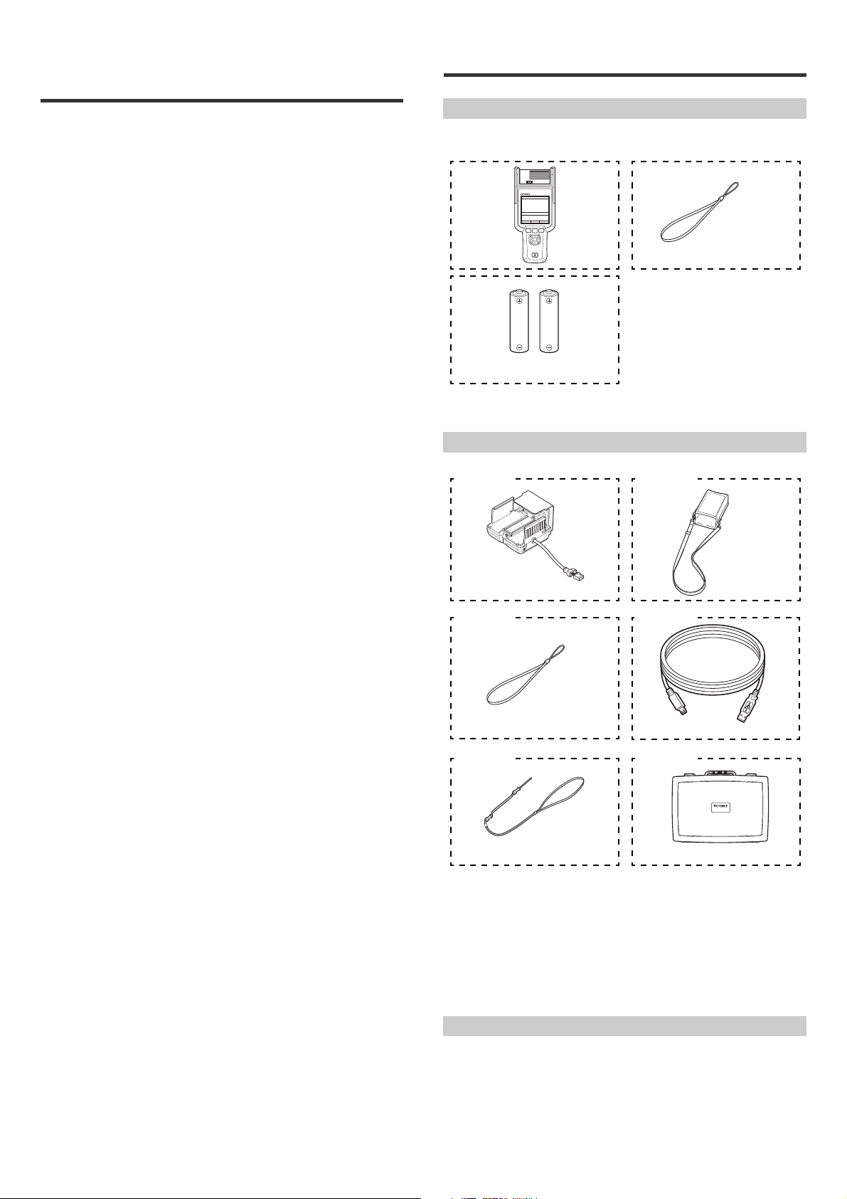
Main unit x1
Strap x1
AA dry cell battery x2
(for operation confirmation)
SK-H055
Ionizer monitoring unit
OP-87928
Handheld unit case
OP-87929
Strap
OP-51580
Mini-B USB cable (2 m)
OP-87930
Neck strap
OP-87931
Storage case
OP-87927
Ion monitor unit grounding wire
OP-87926
Grounding wire for handheld unit
Standards
CE marking
Keyence Corporation has confirmed that this product complies with the essential
requirement of the applicable EC Directives, based on the following specification.
Be sure to consider the following specification when using this product in the
Member States of European Union.
z EMC directive
• Applicable standard EN61326-1, Class A
• This product is intended to be used in an industrial electromagnetic
environment.
<Remark>
These specifications do not give any guarantee that the end-product with this
product incorporated complies with the essential requirement of EMC Directive.
The manufacturer of the end-product is solely responsible for the compliance on
the end-product itself according to EMC Directive.
z Low-voltage directive
• Applicable standard EN60825-1, Class 1 Laser Product
CSA Certificate
This product complies with the following CSA and UL standards and has been
certified by CSA (Class 2252 05/Class 2252 85).Be sure to consider the following
specifications when using this product as a product certified by CSA.
z Applicable Standard
CAN/CSA C22.2 No.61010-1,
Safety Requirement for Electrical Equipment for Measurement, control,
and Laboratory Use
UL61010-1
Safety Requirement for Electrical Equipment for Measurement, control,
and Laboratory Use
<Precautions>
• Overvoltage Category(Installation Category): I
• Pollution Degree:2
• Use this product at the altitude of 2000m or less
• Indoor use only.
• Do not use this product in a manner not specified herein. It may result in fire,
electric shock or malfunction.
FDA (CDRH) regulations
This product complies with the following FDA (CDRH) regulations.
• Applicable standards FDA (CDRH) part 1040.10, class 1 laser product
The laser classification is implemented on the basis of IEC 60825-1 following the
requirements of Laser Notice No. 50 of the FDA (CDRH).
FCC regulations
This product complies with the following EMI regulations specified by the FCC.
• Applicable standards FCC part 15 subpart B, class A digital device
This device complies with part 15 of the FCC Rules. Operation is subject to the
following two conditions:
(1) this device may not cause harmful interference, and
(2) this device must accept any interference received, including
interference that may cause undesired operation.
IC (Industry Canada) regulations
This product complies with the following EMI regulations specified by IC.
• Applicable standards ICES-003, class A digital apparatus
This Class A digital apparatus complies with Canadian ICES-003.
1. Before Use
Checking the Package Contents
The following equipment and accessories are included in the package. Before
using the unit, make sure that all items are included.
Grounding wire x1
Instruction manual x1 (this document)
Options
STATIC SENSOR
PC Application Software for the SK-H
You can use PC application software to read measured data from the unit's
memory to a PC.
The data on the unit is read as CSV files.
You can download the software from the KEYENCE website.
(http://www.keyence.com)
For details on the software, visit the KEYENCE website.
3
E SK-H
Page 4
Part Names and Functions
SK-H050
IMU
No.001
NEAR
V
°C %
-38
29.0 47
8/28 15: 02
15: 18
MENU START RANGE
(1)
(2)
(3)
(4)
(6)
(5)
(7) (10)
(9) (8)
NOTICE
(1)
(4)
(5)
(2)
(3)
Ta b
Names of Parts of the Display
No.001
NEAR
15: 18
8/28 15: 02
Name
This part includes the surface potential sensor and the laser
(1) Sensing unit
(2) Display Displays the measured value and each setting item.
(3) F1 key
(4) F2 key
(5) F3 key
(6) Arrow keys Used to select setting items and to move the screen.
(7) Power key Used to turn the power on and off.
(8) USB port Connect a USB cable to this port to connect the unit to a PC.
Grounding connector/
(9)
IMU connector
(10) Battery compartment Insert two AA dry cell batteries in this compartment.
emitter.
The sensing unit can be rotated 180°.
* The sensing unit cannot be rotated when the ionizer
monitoring unit is installed.
Mainly used to display the MENU screen and to cancel
settings. The operation varies depending on the screen.
Mainly used to confirm the selected item and to start/stop
measurement. The operation varies depending on the screen.
Mainly used as the ZERO button and to switch the range. The
operation varies depending on the screen.
Connect the grounding wire to this connector. When using an
IMU (ion monitor unit), connect its cable to this connector.
Description
-38
29.0 47
°C %
V
MENU START RANGE
Name
(1) Battery Display Displays the remaining battery charge
(2) Main display
(3) F-key operations
(4) Time display Displays the date and time
(5) Title display Displays the title of the contents shown in the main display
Displays information such as the measured value and
setting items
Displays the operations of, from the left, the F1, F2, and F3
keys
Description
Preparing for Measurements
Replacing the batteries
1 Remove the battery cover.
Unlock and then remove the battery cover.
2 Replace the batteries.
Ensure that you insert the batteries in the correct position.
E SK-H
3 Attach the battery cover.
Attach and then lock the battery cover.
If you will not use the unit for a long time, remove the batteries.
4
Page 5

Initialization
Mode
Response
Utility
Initialize
Static Meter
0.8s
>
>
15: 19
BACK ENTER
MENU
Mode
Response
Utility
Initialize
Static Meter
0.8s
>
>
15: 19
BACK ENTER
MENU
1 From the measurement screen,
press the "MENU" (F1) key to
display the MENU screen.
2 Select "Initialize" and then press
the "ENTER" (F2) key.
2. Operation Menus and
Measurement Procedures
Setup Screen
Switching to the setup screen
From the measurement screen, press the "MENU" (F1) key. The MENU screen is
displayed.
3 On the "Initialize" menu, the
"Results" and "Factory default"
items are displayed. Select the
item that you want to initialize,
and then press the"ENTER" (F2)
key.
Results: Only the measured data will be
initialized.
Factory default: The measured data
and all settings other than the date and
time will be reset to their default values.
15: 19
0.8s
>
>
Mode
Response
Utility
Initialize
MENU
Static Meter
BACK ENTER
List of setting items
Setting item Details
Mode Select the measurement mode.
Response Set the response time.
Utility
Initialize Initialize the measured data and settings.
Setting details
z Mode
Set the measurement mode.
Setting item Details
Static Meter
Charge Plate
z Response
Set the measurement response time.
Setting item Details
Response 0.1s/0.2s/0.4s/0.8s/1.6s/3.2s/6.4s 0.8s
* This can only be set during charging potential measurement mode.
z Utility
Configure settings such as the date and time and the operation sound - for a
variety of functions.
Setting item Details
Date Set the date and time.
Sound
Backlight
Sleep
Laser Pointer
Area Scaling
* Area Scaling Function
This function corrects errors in the measured value due to size differences of the
measurement targets by setting a correction value according to the size of the
target.
Configure functional settings such as the date and time, operation sound,
and backlight.
Default
value
Charge potential measurement mode: The electric charge of the
target will be measured.
Charge plate monitor mode
With an IMU (ionizer monitoring unit) connected, the static
elimination speed and ion balance of the static eliminator will be
measured.
To use this mode, an optional ionizer monitoring unit is required.
*
Turn the operation sound on or off.
Setting item: ON/OFF
Set the display backlight. When this is set to "Auto," the
backlight will remain on for a fixed length of time after an
operation is performed.
Setting item: Auto/ON/OFF
When no operations are performed for the set time, the unit
will automatically turn off.
Setting item: OFF/3min/5min/10min/15min/30min
Turn the laser emission on or off.
Setting item: ON/OFF
Set the area scaling.
Setting Items: Near/FAR (setting range: 0.1 to 1.5)
{
Default
value
Default
value
ON
Auto
OFF
ON
Near: 1.0
Far: 1.0
5
E SK-H
Page 6

(Setting procedures)
1. Press the F1 key in “MENU”
and select “Utility.”
2. Select “Area Scaling.”
3. Select “Near mode” or
“Far mode.”
4. Set a value using the T/S keys
and press the “ENTER” key.
Mode
Response
Utility
Initialize
Static Meter
0.8s
>
>
18: 11
BACK ENTER
MENU
Date
Sound
Backlight
Sleep
Laser Pointer
Area Scaling
>
OFF
AUTO
3min
ON
>
>
18: 11
BACK ENTER
Utility
Near
Far
1.0
1.0
22: 07
BACK ENTER
Area Scaling
1.0
19: 14
BACK ENTER
Near
Near mode
Measurement
area
Measured
value
φ20 mm 0.6
φ40 mm 0.7
φ60 mm 0.8
φ80 mm 0.9
φ120 mm 1.0
Far mode
Measurement
area
Measured
value
φ120 mm 0.7
φ200 mm 0.9
φ300 mm 1.0
φ400 mm 1.1
φ500 mm 1.2
φ660 mm 1.3
No.001
NEAR
8/28 15: 02
15: 18
OKFar Near
Press the "START" F2 key to start the
measurement.
Press the "STOP" F2 key again
to stop the measurement.
(1) Current value display (2) Maximum value display
(4) Absolute value display (3) Minimum value display
W/X keys
W/X keys W/X keys
W/X keys
• Refer to the correction table shown below to setting the correction value.
z Using the laser pointers to align the unit
The laser pointers are used to align the unit with the measurement distance
of the selected range.
Perform the alignment as shown below.
The position at which the laser line and the laser point overlap indicates the
correct measurement distance.
5 Perform the measurement.
Check the laser pointers to confirm that the target is at the correct
measurement distance.
z Initialize
Initialize the measured data or settings.
Initialize Details
Results Only the measured data will be initialized.
Factory default
The measured data and all settings other than the date and time will be
reset to their default values.
Procedure for Measuring Charge Potential
1 Turn the power on.
Press the power button. The main unit turns
on and displays the start screen.
2 Press the F1 key to display “MENU.”
Select “Static Meter” from “MODE.”
3 Select the range.
Press the "RANGE" (F3) key to select the
range.
Each time that you press the "RANGE" (F3)
key, the range switches between "Near" and
"Far."
Near (high-precision mode)
Far (wide-range mode)
Measurement distance: 25 mm.
Measurement range: 0 to ±2 kV
Measurement distance: 100 mm.
Measurement range: 0 to ±50 kV
15: 18
No.001
NEAR
-38
29.0 47
MENU START RANGE
When the measurement stops, the record is automatically saved.
The current value when measurement is stopped (electric charge/humidity/
temperature) and the maximum value/minimum value/absolute value (only for
the electric charge) during measurement are saved.
Records are saved from number 001 to number 100. Note that if a
measurement is performed with a record number in which data has already
been saved, the existing data will be overwritten. If you press the "CANCEL" F1
key to cancel a measurement that has started, the unit will return to the state
that it was in prior to the measurement starting. Switch to the record number
that you will use, and then start the measurement.
Hold down the F2 key when measurement is stopped to delete the data of the
displayed record number.
z List of screens in charging potential measurement mode
You can use the W and X arrow keys to switch between displays.
You can switch between displays regardless of whether a measurement is
in progress or not.
No.001
NEAR
29.0 47
MENU START RANGE
8/28 15: 02
°C %
8/28 15: 02
-38
°C %
V
15: 18
V
No.001
NEAR
-38
29.0 47
CANCEL STOP ZERO
No.001
NEAR
29.0 47
MENU START RANGE
15: 18
8/28 15: 02
V
°C %
15: 19
MAX
8/28 15: 02
+
9
V
°C %
4 Perform the zero-point
adjustment.
Press the "START" (F2) key to switch
the unit to the measurement state.
Point the unit at a grounded target,
and then press the F3 key.
Press the "STOP" (F2) key to stop the
measurement.
This completes the operation.
E SK-H
15: 20
ABS
No.001
NEAR
29.0 47
MENU START RANGE
8/28 15: 02
-40
°C %
V
No.001
NEAR
-40
29.0 47
MENU START RANGE
15: 20
MIN
8/28 15: 02
V
°C %
6
Page 7

No.002
z Record number switching
You can use the S and T keys to switch
the record number.
* You can only switch between record
number screens when the unit is not
performing a measurement. You can
switch the record number regardless of
the display mode.
If the record number is 100 and you
continue to switch it forward, the record
number will return to 1.
Lock cover
Unlocked
CAUTION
Lock cover
Locked
No.005
9/05 9: 21
9: 21
Ion Balance
Press the "START" (F2) key to
start the measurement.
Press the "STOP" (F2) key to
stop the measurement.
No.001
8/23 16: 12
15: 52
Decay+
Press the "START" (F2) key to
charge the monitor and start the
measurement.
When the voltage drops below
100 V, stop the measurement of
the time.
NEAR
15: 18
8/28 15: 02
4 Cover the connector with the lock cover to fix the cable in place, and
then connect the grounding wire.
Connect the grounding wire to the grounding terminal on the side of the ionizer
monitoring unit. Use D-class grounding.
----
−−.− −−
MENU START RANGE
V
°C %
6 Turn the power off.
Press the power button again.
The unit turns off.
Measurement Procedure in Charge Plate Monitor Mode
In charge plate monitor mode, three types of measurements are possible: ion
balance (IB), positive static elimination speed (Decay+), and negative static
elimination speed (Decay-).
Measurement
Measurement Details
Ion Balance This mode measures the ion balance.
Decay+
Decay-
This mode charges the IMU unit to a positive voltage and measures the
static elimination time.
This mode charges the IMU unit to a negative voltage and measures the
static elimination time.
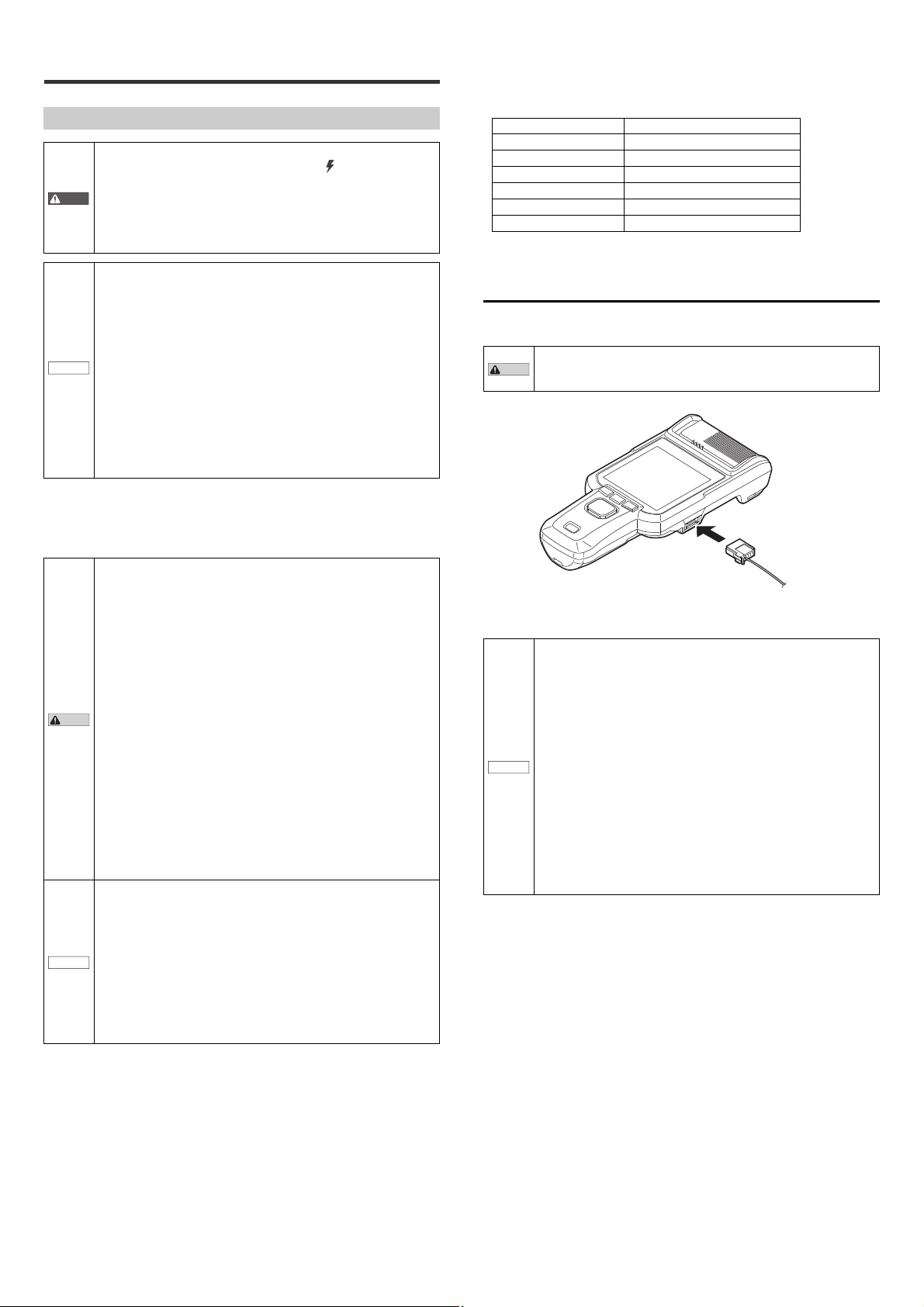
Connecting the ionizer monitor (SK-H055)
1 Insert the SK-H into the ionizer monitoring unit.
Insert the SK-H as far as possible.
Before you attach the IMU unit, check that the sensor unit is
facing the front. Attaching the IMU unit with the sensor unit not
facing the front prevents the unit from performing accurate
measurements, which may lead to product breakdown or damage.
Ion balance measurement procedure
1 Turn the power on, and then press the "MENU" (F1) key to display
the "MENU" screen.
Under "MODE," select "Charge Plate."
2 Select "Ion Balance" as the item to
measure.
Use the W and X keys to switch between
the screens until "Ion Balance" is
displayed at the top of the screen.
3 Perform the measurement.
Point the unit at the location to be measured.
2 Slide the lock on the back of the ionizer monitoring unit until you
hear a click.
3 Insert the ionizer monitoring unit's connector cable into the
connector of the SK-H until you hear a click.
Unlock the lock cover, and then insert the ionizer monitoring unit’s connector
cable into the connector of the SK-H while ensuring that the lock cover does
not cover the connector.
Ion Balance
No.005
1.5
+
25.3 54
MENU START ZERO
°C %
9: 21
9/05 9: 21
sec
2
V
Ion Balance
No.005
1.5
+
25.3 54
CANCEL STOP
°C %
Static elimination time measurement procedure
1 Turn the power on, and then press the "MENU" (F1) key to display
the "MENU" screen.
Under "MODE," select "Charge Plate."
2 Select "Decay+" or "Decay-" as the
item to measure.
Use the W and X keys to switch between
the screens until "Decay+" or "Decay-" is
displayed at the top of the screen.
3 Perform the measurement.
Point the unit at the location to be measured.
.−s
15: 52
−−−
10 15s
No.013
1.0
0.1
0kV
CANCEL STOP
Decay +
0.8s
10
No.001
1.0
0.1
0kV
Reference
Decay +
−−
50
MENU START
To stop the measurement, press "STOP." Alternatively, the
measurement stops automatically after 99 seconds elapse.
7
9: 21
9/05 9: 21
sec
2
V
15: 22
+
9V
23s
E SK-H
Page 8

z Saving records
Reference
CAUTION
No.004
9.4s
10 15s
+40
−
2v
−40
0V
50
15: 53
MENU START SCALE
Ion Balance
No.012
1.1s
23s
0kV
−0.1
−32V
−1.0
10
15: 23
MENU START
Decay
−
No.013
0.8s
23s
1.0
0.1
+
9V
0kV
10
15: 22
MENU START
Decay +
No.005
V
°C %
+
2
sec
1.5
25.3 54
9/05 9: 21
9: 21
MENU START ZERO
ZERO ZERO
ZERO
Ion Balance
No.002
V
°C %
+
32
sec
1.0
26.8 50
8/23 16: 12
15: 52
MENU START
Decay +
No.003
V
°C %
−24
sec
0.2
29.5 46
8/28 15: 23
15: 23
MENU START ZERO
Decay
−
No.002
V
°C %
+
2
sec
1.5
25.3 54
9/05 9: 21
9: 21
MENU START ZERO
Ion Balance
(1) IB value display
W/X keys*
(2) IB graph display (3) Decay+ value
display
W/X keys
(6) Decay- graph
display
(5) Decay- value
display
(4) Decay+ graph
display
z Record number switching
You can use the S and T keys to switch the
record number.
W/X
keys
W/X
keys*
W/X
keys
W/X
keys*
No.005
V
°C %
+
2
sec
1.5
25.3 54
9/05 9: 21
9: 21
MENU START ZERO
Ion Balance
77.6
183.3
62.8
34.5
47.7 31.6
Unit: mm
When the measurement stops, the record is automatically saved.
The current value when measurement is stopped (electric charge/humidity/
temperature) and the ion balance measurement time or the static elimination
time are saved.
Records are saved from number 001 to number 100. Note that if a
measurement is performed with a record number in which data has already
been saved, the existing data will be overwritten. If you press the F1 key to
cancel a measurement that has started, the unit will return to the state that it
was in prior to the start of measurement. Switch to the record number that you
will use, and then start the measurement.
Hold down the F2 key when measurement is stopped to delete the data of the
displayed record number.
z List of screens in charge plate monitor mode
You can use the W and X arrow keys to switch between the screens.
You cannot switch to the screen marked with "*" during
measurement.
You can only switch between record number screens when the unit is
not performing a measurement. You can switch the record number
regardless of the display mode. If the record number is 100 and you
continue to switch it forward, the record number will return to 1.
z How to execute zero point adjustment in charge plate monitor mode
1 Select a screen on which the F3
"ZERO" key is displayed.
Switch the screen using the W/X keys, and
then check that "ZERO" is displayed for the
F3 key.
3. Specifications
Specifications
SK-H050
Measurement mode
Measurement distance
Charging
potential
measurement
Temperature
measurement
Humidity
measurement
Charge
plate
monitor
function
Laser class
PC interface
Ratings
Environmental resistance
Materials
Weight
*1 When measured with a response time of 0.8s, this is ±100 V or less in high-precision mode
*2 The measurement accuracy range is ± 30 kV.
*3 At 25°C and with a humidity of 50%RH
*4 SK-H055 is necessary.
*5 When ±100 V or less. Other ranges are ±10% (indicated value).
*6 The laser classification is implemented on the basis of IEC 60825-1 following the
*7 10 to 60%RH when using the SK-H055.
Measurement range
Measurement accuracy
Minimum display unit
Sampling rate
Measurement range
Measurement accuracy
Minimum display unit
Sampling rate
Measurement range
Measurement accuracy
Minimum display unit
Sampling rate
Ion
balance
measurement
mode
Static
*4
elimination time
measurement
mode
and ±1 kV or less in wide-range mode, and ±10% (indicated value) in other ranges.
requirements of Laser Notice No. 50 of the FDA (CDRH).
Ion balance
measurement range
Measurement
accuracy
Measured voltage
minimum display unit
Charge voltage
Static elimination time
minimum display unit
Measurement time
Power supply voltage
Operation time
Ambient temperature
Ambient humidity
*1
*3
*3
*5
Dimensions
SK-H050
High-precision mode
*7
Wide-range mode
25 mm 100 mm
±2 kV ±50 kV
±10 V ±100 V
0 to 999 V : 1 V
1.00 to 9.99 kV : 0.01 kV
10.0 kV or more : 0.1 kV
Approx. 1.4 ms
0 to 40°C
±1°C
0.1°C
1 s
10% to 85% RH
±5% RH
1% RH
1 s
±1 kV
±10 V
1 V
±1400 V
0.1 s
0 to 99 s
Class 1 Laser Product
(IEC60825-1: 2007
FDA(CDRH)Part1040.10*6)
USB 2.0 Full Speed
AA alkaline dry cell battery × 2
8 hours (in charge potential
measurement mode)
0 to 40°C (no freezing and no
condensation)
10 to 85%RH (no condensation)
SK-H050: PC-ABS, PC, SUS
SK-H055: PC, SUS, PTFE, PVC
SK-H050: Approx. 240 g
SK-H055: Approx. 220 g
*2
2 Execute zero point adjustment.
Direct the unit toward the target that
is grounded, and press the F3
“ZERO” key.
E SK-H
8
Page 9

With the IMU SK-H055 installed
83.9
197.8
63.7
61.3
Unit: mm
4. Appendix
Error Messages and Corrective Actions
Error display Error description Corrective action
Low Battery
Factory value is broken.
Please confirm wiring.
Memory error is occurred.
IMU is not connected.
IMU is overcharged.
Please discharge it.
Failed to charge.
Please replace batteries.
Failed to adjust zero.
Hardware Error Hardware error.
* Correctable range: NEAR: ±500 V, FAR: ±5 kV
The remaining battery charge
is insufficient.
Reading the nonvolatile
memory storage data failed.
An overcurrent is flowing
through the grounding wire or
IMU connector.
Reading/writing the
nonvolatile memory storage
data failed.
IMU is not connected during
charge plate mode.
A high voltage has been
already applied to the IMU
plate.
The remaining battery charge
is insufficient for the charge.
An attempt was made to store
a voltage that is invalid or is
not within the correctable
range as the zero point.
Replace the AA batteries with
new ones.
• Cycle power
• If the same error occurs,
contact your nearest
KEYENCE office.
Check that the unit has been
wired correctly.
Press the F2 key to recover
from the error, but the unit will
reset its settings to their
default values and restart.
Press the F2 key to recover
from the error. Connect IMU.
Press the F2 key to recover
from the error. Discharge the
charge plate, by temporarily
grounding it, and then
perform the operation again.
Press the F2 key to recover
from the error. Replace the AA
batteries with new ones.
Press the F2 key to recover
from the error. Check that the
measured value is within the
correctable range*, and then
perform the zero-point
adjustment again.
• Cycle power
• If the same error occurs,
contact your nearest
KEYENCE office.
9
E SK-H
Page 10

WARRANTIES AND DISCLAIMERS
(1) KEYENCE warrants the Products to be free of defects in materials and
workmanship for a period of one (1) year from the date of shipment. If any
models or samples were shown to Buyer, such models or samples were used
merely to illustrate the general type and quality of the Products and not to
represent that the Products would necessarily conform to said models or
samples. Any Products found to be defective must be shipped to KEYENCE
with all shipping costs paid by Buyer or offered to KEYENCE for inspection and
examination. Upon examination by KEYENCE, KEYENCE, at its sole option,
will refund the purchase price of, or repair or replace at no charge any Products
found to be defective. This warranty does not apply to any defects resulting
from any action of Buyer, including but not limited to improper installation,
improper interfacing, improper repair, unauthorized modification, misapplication
and mishandling, such as exposure to excessive current, heat, coldness,
moisture, vibration or outdoors air. Components which wear are not warranted.
(2) KEYENCE is pleased to offer suggestions on the use of its various Products.
They are only suggestions, and it is Buyer's responsibility to ascertain the
fitness of the Products for Buyer’s intended use. KEYENCE will not be
responsible for any damages that may result from the use of the Products.
(3) The Products and any samples ("Products/Samples") supplied to Buyer are not
to be used internally in humans, for human transportation, as safety devices or
fail-safe systems, unless their written specifications state otherwise. Should any
Products/Samples be used in such a manner or misused in any way,
KEYENCE assumes no responsibility, and additionally Buyer will indemnify
KEYENCE and hold KEYENCE harmless from any liability or damage
whatsoever arising out of any misuse of the Products/Samples.
(4) OTHER THAN AS STATED HEREIN, THE PRODUCTS/SAMPLES ARE
PROVIDED WITH NO OTHER WARRANTIES WHATSOEVER. ALL
EXPRESS, IMPLIED, AND STATUTORY WARRANTIES, INCLUDING,
WITHOUT LIMITATION, THE WARRANTIES OF MERCHANTABILITY,
FITNESS FOR A PARTICULAR PURPOSE, AND NON-INFRINGEMENT OF
PROPRIETARY RIGHTS, ARE EXPRESSLY DISCLAIMED.
IN NO EVENT SHALL KEYENCE AND ITS AFFILIATED ENTITIES BE
LIABLE TO ANY PERSON OR ENTITY FOR ANY DIRECT, INDIRECT,
INCIDENTAL, PUNITIVE, SPECIAL OR CONSEQUENTIAL DAMAGES
(INCLUDING, WITHOUT LIMITATION, ANY DAMAGES RESULTING FROM
LOSS OF USE, BUSINESS INTERRUPTION, LOSS OF INFORMATION,
LOSS OR INACCURACY OF DATA, LOSS OF PROFITS, LOSS OF
SAVINGS, THE COST OF PROCUREMENT OF SUBSTITUTED GOODS,
SERVICES OR TECHNOLOGIES, OR FOR ANY MATTER ARISING OUT OF
OR IN CONNECTION WITH THE USE OR INABILITY TO USE THE
PRODUCTS, EVEN IF KEYENCE OR ONE OF ITS AFFILIATED ENTITIES
WAS ADVISED OF A POSSIBLE THIRD PARTY’S CLAIM FOR DAMAGES
OR ANY OTHER CLAIM AGAINST BUYER. In some jurisdictions, some of the
foregoing warranty disclaimers or damage limitations may not apply.
BUYER'S TRANSFER OBLIGATIONS:
If the Products/Samples purchased by Buyer are to be resold or delivered to a
third party, Buyer must provide such third party with a copy of this document, all
specifications, manuals, catalogs, leaflets and written information provided to
Buyer pertaining to the Products/Samples.
E 1101-3
Page 11

11
E SK-H
Page 12

Copyright (c) 2014 KEYENCE CORPORATION. All rights reserved.
13444E 1124-1 96M13445 Printed in Japan
E SK-H
12
 Loading...