

Page 1
Easy
3 Step
Guide
Selecting Your First
Vision System
With many different camera, lighting, and controller options, this
guide is designed to help you determine which is the best vision
system for your inspection.
Page 2
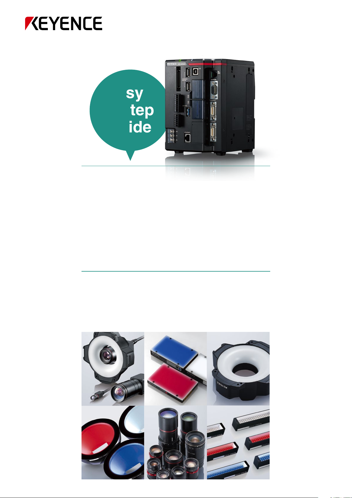
Vision system configuration
First, we'll introduce the overall composition of a vision system. Broadly speaking, a vision system is composed of a "controller"
which processes the images, and a "camera" that captures the object for detection. Their human equivalents would be the
"brain" and "eyes." The "lens," which is attached to the camera, is used to gather light on the image receiving elements, and
"lighting," which is used to appropriately adjust the brightness of the object for detection, are both important components of a
vision system.
Controller
Selection flow
The "camera," "lens," and "lighting" form
the basis for any vision system. To carry
out optimal inspections, proper selection
of these components is essential. In this
document, we will provide some of the
key points to selecting these 3
components.
STEP 1
STEP 2
STEP 3
Camera + Lens + Lighting
Selecting a camera
Selecting a lens
Selecting lighting
2
Page 3
STEP 1
Selecting a camera
Verify the "minimum detection size" needed to find the object for detection
1
The "minimum detection size" refers to the smallest feature that a vision system will be able to detect with stability. Understand the size of the features
(defects, foreign particles, text/barcodes) that need to be detected, and understand what kind of capabilities the camera must have to find them.
0.31 megapixel
Differences in
camera capabilities
(number of pixels)
camera
Foreign particles are
blurry and hard to detect
Calculate the minimum detection size
Next, we'll introduce an example of the calculation to decide the minimum detection
size the system will be capable of processing. Minimum detection size is calculated
from approximate values for the following elements.
= Number of pixels in the camera's capture range (Y axis) (Pixels)
A
= Field of view (Y-axis) (mm or inches)
B
= Minimum detection pixel size for image sensor elements (Pixels)
C
Minimum detection size =
B ÷ A × C
2 megapixel
camera
Foreign particle
detection capability
C = Minimum detection
pixel size
Camera
A = Image sensor size (Y)
Lens
Foreign particles
B = Field of view (Y)
For example:
Let's think about the minimum detection size when (B) is set to 30 mm.
We'll compare a standard type 0.31 megapixel camera (Y = 480 pixels) and a high pixel-count type
2 megapixel camera (Y = 1200 pixels) for (A). The minimum detectable pixel size, (C), would generally be "4 × 4 pixels."
* The target minimum detectable pixel size changes depending on the object for detection and the inspection environment.
Minimum detection size when
using 0.31 megapixel camera
Minimum detection size = 30 ÷ 480 × 4 = 0.25 mm Minimum detection size = 30 ÷ 1200 × 4 = 0.1 mm
If the goal of the inspection is "to detect ø0.1 mm debris within a 30 mm vision field,"
then it is necessary to select a camera with 2 megapixels or higher.
Check
POINT
What is the size of the object that needs to be detected?
Minimum detection size when
using 2 megapixel camera
3
Page 4
Select the optimal camera based on the "minimum detection size"
2
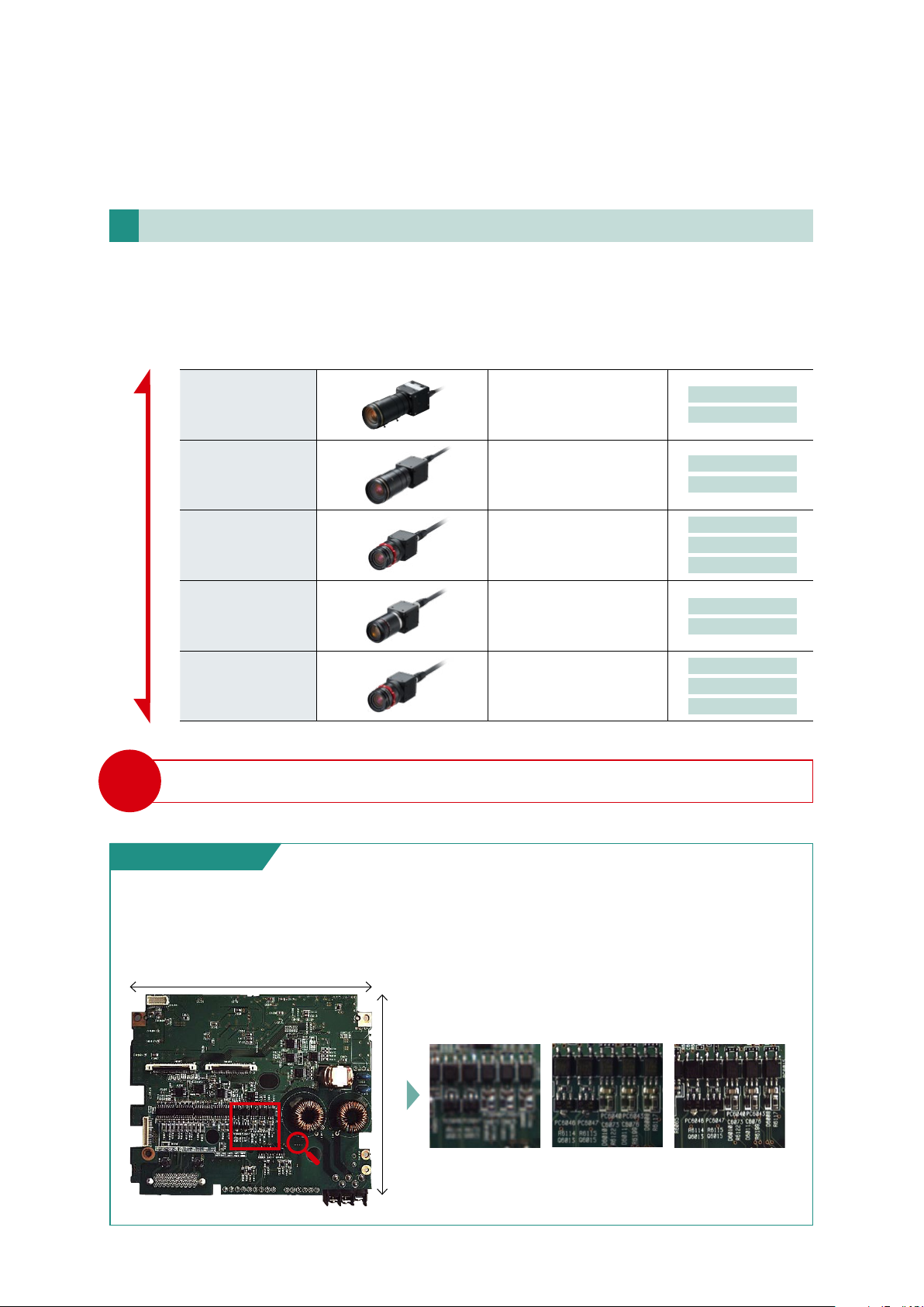
In general, as the number of pixels increases, increasingly smaller objects can be detected, but costs also increase.
It is important to select a camera that meets the "minimum detection size" requirement and is appropriate for the inspection. There are more than
20 types of cameras in the KEYENCE lineup. Beyond the number of pixels, choices such as monochrome or colour, compact or standard size and
so forth allow for selection of the optimal model for the application.
High precisionLow cost
Check
POINT
21 megapixels
5 megapixels
2 megapixels
0.47 megapixel
0.31 megapixel
What camera specifications are necessary?
Capture range
5104 × 4092 pixels
Capture range
2432 × 2040 pixels
Capture range
1600 × 1200 pixels
Capture range
784 × 596 pixels
Capture range
640 × 480 pixels
Colour
Monochrome
Colour
Monochrome
Colour
Monochrome
Compact model available
Colour
Monochrome
Colour
Monochrome
Compact model available
KEYENCE Technology
The power of a 21 megapixel camera
This camera can capture high resolution images with a valid pixel count of 21 megapixels (5104 × 4092 pixels). It can detect minute
defects and inspect small components on large work pieces.
140mm
0.31 megapixel camera
120mm
4
5 megapixel camera 21 megapixel camera
It is possible to
check fine details of
the inspection target.
Page 5

Confirm the time needed for inspection
3
When performing image inspection, it is necessary to think about processing speed. The latest vision systems are capable of ultra-high speed
processing, and depending on what is to be inspected, they can perform 100 inspections in just one second. However, because the image
processing time can vary greatly based on the camera's resolution, the contents to be processed, and the number of processing items, it is
important to confirm the vision system's processing speed and the inspection line's takt time.
Image processing flow
Trigger Input
PLC PLCPCSensors,
Image Capture
Image Processing
Judgment Output
Image sensor processing time Converted to inspection takt time
other
Capture and
Transmission
Image processing
controller
The camera captures an image, then sends the image data to the controller.
The captured image is processed. Depending on the inspection items, the presence or absence of foreign
particles, dimensions, position, quantity, etc. can be inspected.
A judgment result of whether or not the product is defective is output.
Capture and transmission time: several ms to several dozen ms
Image processing: several ms to several hundred ms
Image
Processing
Judgment
Output
Control
Several hundred objects/minute to
several thousand objects/minute
The relationship between camera resolution (number of pixels) and processing time
As the number of pixels the camera can capture increases, resolution capability
increases, but processing time becomes longer. An example of detection of
black dots in a container using 0.31 megapixel, 2 megapixel and 5 megapixel
cameras is shown below. When the binarised number of pixels of the same field
of view is compared between each of the cameras, it is easy to see that there is
a large difference in the number of inspection pixels, and that as the number of
pixels increases, more detailed detection is possible. As a result, we see that the
processing time becomes longer the higher the pixel count is.
* The numbers below are representative examples of processing time and number of pixels, with
processing time using the fastest trigger interval.
0.31 megapixel camera 2 megapixel camera 5 megapixel camera
pixels
3
23
pixels
pixels
55
2432 × 2040
1600 × 1200
640 × 480
Check
POINT
7 ms 32 ms 64 ms
What is the inspection takt time? (How long does image processing take?)
5
Page 6

STEP 2
Selecting a lens
Determine a field of view (image capture range) that will include the work piece size and any variations in the conveyor system
1
Determine the scope or range that will be captured by the camera, taking into account the size of the work pieces and the variation in positioning on
the line when transporting work pieces.
Field of view (image capture range)
Deviation amount
Maximum target
size
Check
POINT
2
The lens focal distance which can capture the target field of view for inspection as determined above is called the working distance (WD). In other words,
what position can the camera be installed in? Determine in advance the possible installation locations based on the facilities, equipment and
environment.
What is the maximum size of the inspection target? / Is there any misalignment in the process?
Determine the installation distance to maintain the required viewing angle (working distance)
The focusing distance (working distance) differs according to the lens. If the field of view for inspection and the WD are known in advance, then it
is possible to choose the most appropriate lens.
Check
POINT
6
What is the installation distance between the camera (lens) and the inspection target? /
Are there physical limitations on the installation environment?
Page 7

Select the optimal lens using the lens chart
3
There are many models of lenses, even within the same series.
A lens can be selected by checking the target field of view and WD on the lens chart.
* CA-LHE series
Example: When installing a CA-LHE series lens with a 21 megapixel camera
The graph (lens chart) below shows a simplified relationship among each lens's focal length, WD, and field of view for the specified camera.
The intersections of the target WD and field of view lines can be used to select the proper focal length.
CA-H2100C
CA-H2100M
series
CA-LHE
attached
Y visual field (mm)
1000
100
10
1
CA-LHE25
CA-LHE12
CA-LHE16
CA-LHE35
CA-LHE50
0.5
1.5
0.5
1.0
1.5
10
5
5
5
10
20
A lens chart is prepared for each lens/
100010010 10000
WD (mm)
camera. These are available in the
catalogue or on the website.
Check
POINT
What lenses are compatible with the desired camera? /
Are there problems with the installation distance?
7
Page 8

STEP 3
Selecting lighting
Select the optimal "method of lighting" to match the inspection contents
1
Lighting is essential to image inspection and helps optimise image capture. The
lighting method is selected based on the inspection target's properties (damage/
shape), whether the surface is flat or curved, whether there is unevenness, and so on.
Lighting method can be divided into 3 major types.
1
Specular reflection type
System in which light specularly reflected from the target is received by the lens.
Effective for targets which reflect easily, such as the surface of metal or glass plates.
2
Diffuse reflection type
System in which light specularly reflected from the target is avoided, and uniform light
is received by the lens. Effective for targets such as glossy surfaces or transparent
films in which glare can occur easily.
Incident
light
Target
Diffuse
reflected light
Absorption
Diffuse
transmitted light
Specular
reflection
Diffuse
reflection
Specular
reflection
Transmitted
light
3
Transparent type (backlight)
System in which the target is illuminated from behind, and the silhouette is detected
using the transmitted light. Effective when reflected light does not provide sharp
contrast, or for detecting complicated profiles.
Select the optimal "lighting colour"
2
Backlight
Method to use complementary colour of the inspection target
In the colour wheel shown to the right, the colours which face each other are called "complementary
colours." For example, the complementary colour for orange is blue. If the inspection target is orange, when
it is illuminated with its complementary colour blue, it is possible to obtain a monochrome image of the
inspection target with crisp contrast.
Detection using complementary colour
Sealing tape is applied. In order to detect presence or absence,
use red and blue lighting separately, then compare the difference in contrast.
Colour image Red LED used Blue LED used
Low grayscale
contrast between
red and
background
Anything red
(blue's
complementary
colour) becomes
darker, and stable
detection is
possible
Yellow
Orange
Green
Blue
Purple
Red
8
Page 9

Ultilise different wavelengths of lighting to achieve the desired image
When using LED lighting to achieve good contrast, it is possible to reflect the differences in dispersion rate by wavelength into the light and
shadow (intensity) differences on the capture screen. The dispersion rate for short wavelength colours like blue is high, while the longer
wavelength colours, such as red, do not disperse easily and have a higher transmission ratio.
Non-visible light Non-visible light
Visible light
Ultraviolet
light
~ 380 780 ~
Because the dispersion rate is high for short wavelength blue colours, diffuse
reflection occurs, and flaws "pop out," making blue an appropriate colour for
detecting minute flaws. Conversely, when trying to avoid the influence of
hairline scratches and so forth on metallic surfaces, a red colour is
appropriate. The longer wavelength and lower dispersion rate of red cause
specular reflection, and flaws are not noticeable.
Check
POINT
3
In addition to the light method and colour, the lighting type (format) can be chosen based on contents to be inspected, background and surrounding
environment. KEYENCE also handles a wide variety of image processing LEDs, and can provide the optimal capture conditions.
What is the optimal lighting method? / What is the optimal lighting colour?
Select the optimal "form" from a wide product lineup
Detection of scratches on the surface of
black steel plate
610 ~ 780590 ~ 610570 ~ 590500 ~ 570460 ~ 500430 ~ 460380 ~ 430
Infrared
RedYellowIndigoPurple GreenBlue Orange
light
(Unit: nm)
Detection of scratches in transparent
material
Coaxial type
CA-DX
There's a wide variety of inspection circumstances. An example is shown below.
Example of specular reflection detection
Example of transparent detection
Check
POINT
What about installation space for lighting? / What form can be installed?
Low angle type
CA-DL
Determination of lighting
based on target and
inspection contents
Determination of lighting
based on target and
inspection contents
Direct ring type
CA-DR
Reflection of lighting on glass surface
1
Want to clarify the difference between glass and background
2
Lighting perpendicular to the target is best
3
Possible to retain space above the target
4
Coaxial lighting is the best choice
The target is metallic and uneven, specular reflection is not even
1
Target edges can be highlighted when transmitted light is used
2
Installation of lighting behind the target is possible
3
Surface lighting (backlight) is the best choice
Backlight type
CA-DS
Dome type
CA-DD
Bar type
CA-DB
9
Page 10

KEYENCE Technology
Perfect when selecting lighting is a challenge!
Multi-spectrum lighting provides unparalleled all-in-one performance
8 colour LEDs, along with the 3 capture modes "Multi-spectrum mode," "LumiTraxTM mode," and "normal lighting mode," are combined to
provide unparalleled performance for colour, shape, gloss and multi-product environments.
Multi-spectrum mode
Inspection of Various Types of
Plastic Caps
Colour camera
The imaging element receives white
light reflected from the target through a
colour filter. This data is then used to
create a colour image.
❚ Conventional Colour Camera
Although some differences are noticeable,
the extracted colours are largely the same.
Multi-spectrum image
capture
❚ Multi-Spectrum Mode
Differences in colour are clearly defined.
Colour analysis is performed for every
pixel based on eight grayscale images
taken at different wavelengths.
UV
B
RRRRGGG
GGGGBBB
G
AM
R
B
IR
W
LumiTraxTM mode Normal lighting mode
G
FR
10
Detect changes in height with
directional lighting
❚ Conventional camera ❚ 1st image capture
Surface conditions interfere with
extraction.
Stamped Character Inspection on
Metal Casting
❚ LumiTraxTM mode
Extraction of only shape (irregularity)
information regardless of surface
conditions.
Lighting conditions can be
optimised for each target
depending on the colour conditions
Illumination using a red LED capable of
clearly viewing the pattern is performed
for alignment shift correction.
Red LED
Printing Appearance
Inspection
A red ink defect appears on a printing
with a blue background.
❚ 2nd image capture
To erase the printed pattern for defect
inspection, illumination using the same
blue colour as the background is performed.
Blue LED
Page 11

Customer focused support system
Please consult with KEYENCE when selecting a vision system.
At KEYENCE, our specialised vision system sales engineers use their knowledge and experience to help you select the optimal models. KEYENCE uses
a direct sales system instead of distribution to be
Customer KEYENCE
Loan a test unit free of charge
able to consult directly with customers to understand their circumstances and concerns.
We want to do "such and
such" an inspection...
Leave it to us!
Direct consultation!
At KEYENCE, we provide highly detailed technical sales support for product selection. We also provide test units free of charge*, which allows you
to confirm solution compatibility with your application prior to purchase.
*Not applicable for some units.
Customer KEYENCE
Can thoroughly
test in advance
Test unit
Support when problems occur & same-day shipping of replacement unit
KEYENCE is able to provide unparalleled after-sales support and service because of the direct sales model. In the event of a problem, product
specialists provide a quick solution. Our contracted partner companies provide first-class support as necessary. Same-day shipment of
replacement units* minimises losses due to equipment problems.
* Not applicable for some units.
Customer
Solid support even
when problems occur
after purchase
Response to problems
KEYENCE
Replacement unit
11
Page 12

IP Rated lensing and lighting options for
dust-proof and drip-proof environments
CA-DBWxP Series
IP67-compliant ring lighting/bar lighting available.
Can be used safely even in environments with dust or liquid droplets present.
CA-LHxP Series
IP64-compliant lens for use in FA locations with dust and vibration.
Screws have been eliminated, so there are no worries about losing focus.
Please visit:
GLOBAL NETWORK
AUSTRIA
BELGIUM
BRAZIL
CANADA
CHINA
The information in this publication is based on KEYENCE’s internal research/evaluation at the time of release and is subject to change without notice.
Company and product names mentioned in this catalogue are either trademarks or registered trademarks of their respective companies. Unauthorised reproduction of this catalogue is strictly prohibited.
Copyright © 2019 KEYENCE CORPORATION. All rights reserved.
CONTAC T YOUR NEARE ST OFF ICE FO R RELE ASE STATUS
CZECH REPUBLIC
FRANCE
GERMANY
HONG KONG
HUNGARY
INDIA
INDONESIA
ITALY
JAPAN
KOREA
www.keyence.com
MALAYSIA
MEXICO
NETHERLANDS
PHILIPPINES
POLAND
ROMANIA
SINGAPORE
SLOVAKIA
SLOVENIA
SWITZERLAND
SAFET Y INFORMATION
Please read the instruction manual carefully in
order to safely operate any KEYENCE product.
TAIWAN
THAILAND
UK & IRELAND
USA
VIETNAM
CVEasySelectionGuide-WW-TG-GB 1119-2
WW11-1039
600V73
 Loading...