


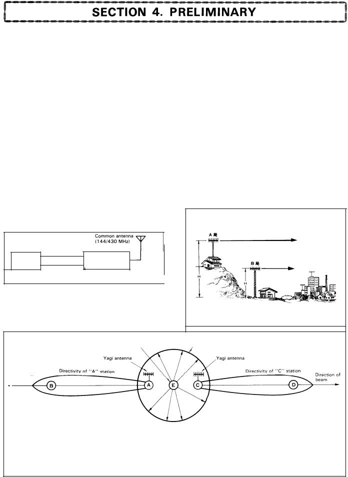
You are the owner of our latest product |
the new TS-780 Duo Band Transceiver. |
|||||||||
This |
unit |
has |
been |
carefully |
engineered |
and |
manufactured |
to rigid |
quality Standards, |
|
and |
should give |
you |
satisfactory |
and dependable |
Operation for |
many |
years. |
|||
We |
suggest |
that you read this instruction |
manual carefully from cover to cover to insure |
|||||||
the |
maximum |
Performance and |
trouble-free |
Operation of your |
new model TS-780. |
|||||
Save the shipping box and packing in the event your unit needs to be transported for remote Operation, maintenance, or Service.
|
CONTENTS |
|
SPECIFICATIONS ............................................................................................. |
2 |
|
1. |
FEATURES ................................................................................................ |
3 |
2. BEFORE USING .......................................................................................... |
4 |
|
3. |
CONTROLS AND THEIR FUNCTIONS ............................................................. |
5 |
4. |
PRELIMINARY.. .......................................................................................... |
9 |
5. |
OPERATING INSTRUCTIONS ....................................................................... |
.1 1 |
6. |
OPTIONAL ACCESSORIES .......................................................................... |
.2 1 |
7. |
TROUBLESHOOTING ................................................................................. |
.22 |
BLOCK DIAGRAM.. .......................................................................................... |
.23 |
|
SCHEMATIC DIAGRAM .................................................................................... |
.24 |
|
TOP § BOTTOM INTERNAL VIEWS.. ................................................................... |
.27 |
|


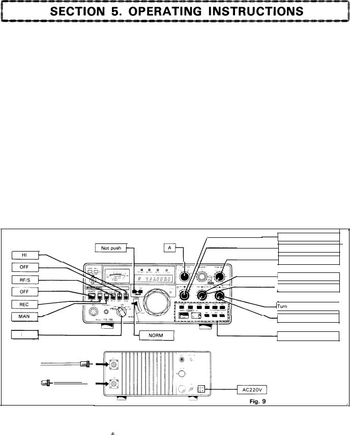
3-l. |
FRONT PANEL |
1 |
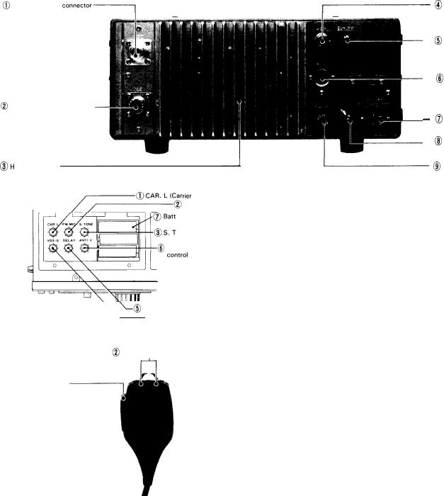
F. LOCK Indicator |
This indicator will light when the LOCK switch is turned ON (VFO frequency is locked).
2 BUSY Indicator
This indicator lights when the squelch is open in FM or.FM-
CH |
receive mode, allowing the Operator to check whether |
||||||||
the |
other Station |
is |
transmitting. |
|
|
|
|||
3 ON AIR |
Indicator |
|
|
|
|
||||
This |
indicator |
will |
light during |
transmission. |
|
||||
4 OFFSET |
Indicator |
|
|
|
|
||||
This |
indicator |
lights |
when the |
TX OFFSET switch is set to |
|||||
the |
D - A |
or |
D |
- |
B Position |
for |
repeater Operation. |
||
5 M e t e r |
|
|
|
|
|
|
|
|
|
This |
meter |
has four functions, each |
being selected |
by using |
|||||
the |
meter select |
switch. |
|
|
|
|
|||
RFIS: |
The meter serves |
as |
“S” |
meter indicating the |
|||||
|
|
strength of received |
Signal |
on a scale graduated |
|||||
|
|
from 1 to 10 (FM), |
or |
1 |
to 9, 9+20 |
dB and |
|||
|
|
9+40 |
dB (SSB CW). |
|
|
|
|||
|
F. LOCK Indicator |
|||
2 |
BUSY |
Indicator |
||
3 |
ON AIR Indicator |
|||
4 |
OFFSET |
Indicator |
||
5 |
Meter |
|
|
|
6 TX-OFFSET Switch |
||||
7 |
REV (Reverse) Switch |
|||
8 |
TONE Switch |
|||
9 |
LOW POWER Switch |
|||
10 |
NB |
(noise |
blanker) Switch |
|
1 1 |
Meter |
Switch |
||
1 2 |
VOX Switch |
|||
13 |
Standby |
Switch |
||
14 |
POWER Switch |
|||
15 |
MIC Connector |
|||
16 |
PHONES |
|
Jack |
|
1 7 |
MODE Switch |
|||
18 |
PRIO. |
|
M |
Switch |
19 |
TIGHT Level |
|||
2 0 |
F. STEP |
Indicator |
||
2 1 |
Tuning |
Knob |
||
22 |
FUNCTION Switch |
|||
23 |
MEMORY Selector |
|||
24 |
S S B |
M I C |
|
|
2 5 |
RIT Indicator |
|||
26 |
RIT |
Control |
||
27 |
IF SHIFT |
Knob |
||
28 |
S Q U E L C H C o n t r o l |
|||
2 9 |
SCAN-W |
|
||
3 0 |
AF GAIN Control |
|||
3 1 |
RF |
GAIN |
Control |
|
32 |
F. STEP Switch |
|||
33 |
RIT Switch |
|||
3 4 |
SCAN Switch |
|||
35 |
H O L D |
|
|
|
36 |
M. S Switch |
|||
37 |
BAND Switch |
|||
38 |
M (Memory) Switch |
|||
39 |
F. LOCK Switch |
|||
4 0 |
M. R |
(Memory Recall) |
||
Switch
During transmission, the meter indicates RF output.
ALC/CEN: In FM receive mode (MODE switch in FM, FM-
CH position), |
the |
meter |
functions as |
a Center |
|
meter. Turn |
the |
VFO |
knob |
to your |
desired |
r e c e i v e Signal |
u n t i l |
t h e |
meter pointer i s |
||
centered. |
|
|
|
|
|
In other operating mode (SSB, CW), the meter indicates the transmitter ALC voltage. In SSB
Operation, adjust the MIC gain |
control so that |
||
the meter pointer deflects within the |
ALC |
zone |
|
on the scale. In CW Operation, |
adjust |
the |
CAR. |
L knob. |
|
|
|
6 TX-OFFSET Switch
This switch is used to shift the TX frequency from the RX frequency for repeater Operation. After the repeater opera-
tion, it |
should be set to the SIMP Position; |
the |
TX |
frequen- |
cy will |
coincide with the RX frequency. In |
case |
of |
Off-band, |
the frequency is not shifted and the transceiver is set in simplex mode.
5


5-5 CW Mode
Reception
Set the controls and switches as outlined in section on
“FM Mode”, except |
that the MODE switch should be set |
to CW. For reception, |
proceed as follows: |
1. Turn the POWER switch ON and adjust the AF GAIN control for suitable volume.
2. Turn the VFO knob slowly for the desired receive Signal
so that a 800 Hz beat is heard. In this way, the frequency of your Station will coincide (Zero-in) with the fre-
quency of your party’s Station.
Similarly, if your Party calls back with a 800 Hz beat in response to your call, it means that the party’s frequen-
cy has coincided with your frequency. Note:
The 800 Hz beat can be checked by using a frequency counter.
Transmission
Adjustments of the transmitter for CW Operation are
basically the same as for FM Operation. The transceiver will be ready for use when adjusted in FM mode provided that the frequencies are the Same.
For transmission, set the controls and switches as outlined in section on “FM Mode”, except that the MODE
switch should be set to CW and the meter switch to ALC/CEN. Connect your key to the KEY jack on the rear Panel.
1. Check to ensure that the MODE switch is set to CW. Set
the standby switch to SEND |
and the ON AIR indicator |
||||
will light. Under this condition, |
press the key down and |
||||
the ALC |
meter should deflect. |
Set |
the standby |
switch |
|
back to |
REC Position. |
|
|
|
|
Note: |
|
|
|
|
|
If the key is not connected, |
the |
ALC meter will |
deflect |
||
when the standby switch is |
set |
to |
SEND. |
|
|
2. Adjust the CAR LEVEL control |
|
|
|
||
With the standby switch in |
the |
SEND Position, |
adjust |
||
the control so that the ALC |
meter |
deflects within the |
|||
ALC zone when the key is pressed down. |
|
||||
Then, release the key. Set the standby switch back to |
|||||
REC Position and the meter |
switch to RF/S Position. |
||||
Note: |
|
|
|
|
If there is a Change in ALC |
meter deflection, reset in the |
|||
Same |
manner as in the SSB mode. |
|
|
|
3. Adjust the side tone |
|
|
|
|
The |
TS-780 has a built-in side tone circuit for monitor- |
|||
ing |
your station’s CW Signal |
during transmission. To |
ad- |
|
just |
the side tone volume, open the top |
cover and |
turn |
|
the SIDE TONE control for desired level. |
|
|||
This |
adjustment should be made in receive mode with |
|||
the |
key pressed down (standby switch in |
REC position), |
||
since, in so doing, the side |
tone circuit |
is activated. |
||
Use of RIT Switch
For detailed information, refer to section on “FM Mode”. Use the RIT switch when your party’s frequency has deviated from 800 Hz or you wish to transmit with a different beat frequency.
Use of NB Switch
Refer to section on “SSB Mode”.
Use of RF GAIN Knob
Refer to section on “SSB Mode”.
Use of IF SHIFT Control
By using the IF SHIFT in conjunction with the RIT, tone quality can be adjusted.
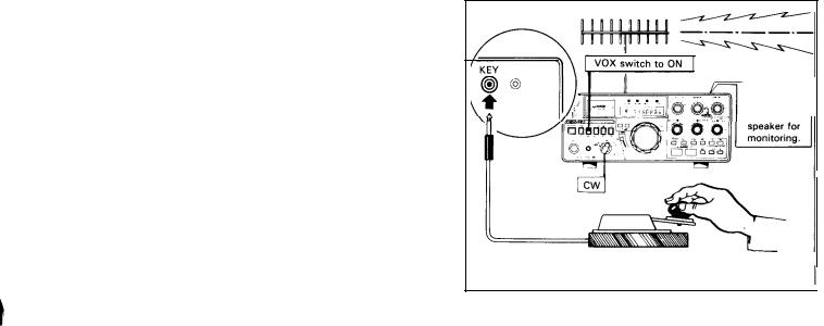
Semi-Break-In |
Operation |
|
The TS-780 is |
capable of semi-break-in Operation, |
in ad- |
dition to the usual CW Operation with the standby |
switch. |
|
The semi-break-in uses the side tone to activate the VOX circuit which switches to transmit when the key is pressed down and to receive when it isreleased. For semi-break-in Operation, set the MODE switch to CW and the VOX switch to ON. Other operating procedures are the same as for the usual VOX Operation (Refer to 5-6).
Side tone is heard
- |
from |
- |
l |
- |
Fig. 15 Semi-break-in Operation
14

5-6 VOX OPERATION
The VOX is an automatic switching System that swit-
ches the transceiver to transmit and receive while speaking into the microphone. This is mainly used in SSB mode.
With the VOX switch set to ON, the transceiver is
automatically switched to transmit mode when you speak
into the microphone and to receive mode when you stop
talking. |
For VOX Operation, the standby switch should be |
set to |
REC. |
Control Settings
1.Adjustment of VOX GAIN Control
With |
the |
standby |
switch |
set to REC, place the VOX |
|||||||||
switch in the VOX (ON) Position. |
|
|
|
|
|||||||||
First turn the VOX GAIN control |
clockwise |
and adjust it |
|||||||||||
so |
that |
the transceiver |
is switched to transmit mode |
||||||||||
when you speak into the microphone with normal voice. |
|||||||||||||
Turn |
the |
control |
further |
clockwise and the gain is |
|||||||||
increased allowing the transceiver to be switched to |
|||||||||||||
transmit mode with a lower level |
|
of |
voice. However, |
||||||||||
excessive VOX gain results in misoperation by ambient |
|||||||||||||
noise. |
|
|
|
|
|
|
|
|
|
|
|
|
|
The condition |
of VOX Operation |
can be checked through |
|||||||||||
the speaker. When any |
Sound is heard from the speaker, |
||||||||||||
it means that the transceiver is in receive mode; other- |
|||||||||||||
wise, it is in transmit mode. In |
transmit mode, the ON |
||||||||||||
AIR indicator Comes on and, in receive mode, the light of |
|||||||||||||
indicator |
goes |
off. |
|
|
|
|
|
|
|
||||
2. Adjustment of ANTI VOX GAIN Control |
|
||||||||||||
This control is located on |
top of |
the |
case |
(sec page 9) |
|||||||||
and is used to prevent the VOX circuit from being |
|||||||||||||
misoperated by the Sound of speaker. |
|
|
|||||||||||
Adjust the VOX GAIN control as directed in item (1) |
|||||||||||||
above. Then, adjust the AF GAIN control for suitable |
|||||||||||||
volume |
while receiving Signals |
from |
a |
Station. |
|||||||||
Hold the microphone 20~ |
30 cm from the speaker and |
||||||||||||
adjust the ANTI VOX GAIN control until speaker Sound |
|||||||||||||
will |
not |
activate |
the |
VOX circuit. |
Excessive |
turning of |
|||||||
the |
control in |
clockwise |
direction |
will Cause the ANTI |
|||||||||
VOX circuit to operate, resulting in failure of the |
|||||||||||||
transceiver to |
be |
switched to transmit |
mode. |
||||||||||
3. Adjustment of VOX DELAY Control |
|
|
|
||||||||||
This control is used to hold the transmitter on after VOX |
|||||||||||||
Operation. If the hold time is |
too short, the TS-780 |
||||||||||||
returns to receive whenever you pause speaking. If too |
|||||||||||||
long, the TS-780 will not |
return to receive after speak- |
||||||||||||
ing. Adjust the control so that the transceiver holds pro- |
|||||||||||||
per transmitting time when you speak at normal Speed. |
|||||||||||||
This control is also effective |
|
for |
CW |
semi-break-in |
|||||||||
Operation. |
|
|
|
|
|
|
|
|
|
||||
During |
|
CW Operation, |
do |
notturn the control excessive- |
|||||||||
ly in clockwise |
direction, |
as it takes a long time until the |
|||||||||||
transceiver returns to receive when the key is released; |
|||||||||||||
making |
it |
impossible |
to |
perform |
smooth |
semi-break-in |
|||||||
Operation. |
|
|
|
|
|
|
|
|
|
|
|||
Note:
If the VOX switch is left ON, the TS-780 will momen-
tarily |
transmit when |
the |
POWER |
switch |
is |
turned on. |
After |
VOX Operation, |
set |
the VOX |
switch |
to |
OFF. |
5-7 READING THE FREQUENCIES
The TS-780 digital display indicates |
carrier positions in |
all operating modes. Because of the use |
of a special circuit, |
the carrier Position remains the same when the MODE switch is manipulated, thus the transmit and receive fre-
quency can be directly read |
on the digital display, except |
|||||
for |
CW reception |
where the |
frequency on the display is |
|||
higher by the beat frequency |
(800 Hz: see |
section on |
“CW |
|||
Mode”) than the transmit frequency. |
|
|
||||
Note: |
|
|
|
|
|
|
The |
digital |
display |
does not |
indicate the |
frequency |
varied |
by |
the RIT |
knob. |
|
|
|
|
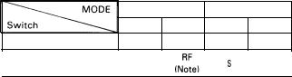
5-8 BAND SWITCH (UP-DOWN)
The BAND switch consists of two pushbutton switches,
UP and DOWN. By pressing the UP switch, the frequency is
shifted up by 1 band and, by pressing the DOWN switch
the frequency is shifted down by 1 band. By holding either switch down, the frequency is shifted continuously at 0.5 seconds intervals. As shown in the illustration below, the
BAND |
switch functions |
separately |
for |
the VFO A and B |
|||
(sec section |
5- 9 on |
“Operation |
of 2 |
VFO’s). |
The |
BAND |
|
switch |
uses |
feather-tauch pushbutton |
switches. |
A |
tone |
||
pulse |
is heard whenever the switch is |
pressed. |
|
|
|||
5-9 DIGITAL VFO
The TS-780 VFO is designed so that the pulses
generated by rotating the VFO knob |
are counted |
by the |
||||||||
microprocessor to vary the frequency |
through PLL |
circuit. |
||||||||
The |
frequency |
is varied step by Step. The step interval |
is |
|||||||
20 |
Hz (SLOW) |
|
for CW and SSB Operation or |
200 |
Hz |
|||||
(FAST) for fast-forward and FM |
Operation. Either step can |
|||||||||
be selected by the S/F switch |
(sec section 5-12). |
|
|
|||||||
|
The adjustable range of the digital VFO is shown |
in |
||||||||
Table 1. |
|
|
|
|
|
|
|
|
||
|
|
|
|
|
|
|
|
|
||
|
|
|
|
|
F.STEP switch |
“OFF” |
F.STEP switch “ON” |
|||
|
|
|
|
|
|
|
|
|
||
|
144 MHz BAND |
1 4 4 , 0 0 0 . 0 0 - |
1 4 4 , 0 0 0 . 0 0 - |
|
||||||
|
145,999.98 |
145.999.80 |
I |
|||||||
|
|
|
|
|||||||
|
|
|
|
|
|
|
|
|
||
|
430 MHz BAND |
4 3 0 , 0 0 0 . 0 0 - |
|
4 3 0 , 0 0 0 . 0 0 - |
|
|||||
|
439.999.98 |
439.999.80 |
|
|||||||
|
|
|
|
|
||||||
|
|
|
|
|
|
|
|
|
|
|
|
|
|
|
|
|
Table |
1 |
|
|
|
Turning the VFO dial in either direction will shift the frequency in endless mode between 144 . 000 . 00 and 145.999.98 In the 144 MHz band. The dial also functions similarly in the 430 MHz band. Note that the upper limit of the band varies according to the Position (ON/OFF) of the F. STEP switch or mode.
15
 Loading...