


Installation Instructions
Instrucciones de instalación
Instructions pour l'installation
English / Español / Français
Table of Contents / Índice / Table des matières......2
Models/Modelos/Modèles: 110.2810*
Kenmore®
Top-Loading High Efficiency Low-Water Washer
Lavadora de alto rendimiento y carga superior, con nivel bajo de agua
Laveuse haute efficacité à faible consommation d’eau avec chargement par le dessus
* = color number, número de color, le numéro de la couleur
P/N W10550315B
Sears Brands Management Corporation
Hoffman Estates, IL 60179 U.S.A.
www.kenmore.com
www.sears.com
Sears Canada Inc.
Toronto, Ontario, Canada M5B 2C3
www.sears.ca
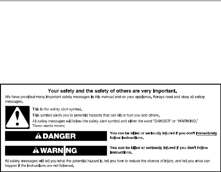
Table of Contents
WASHER SAFETY 2
INSTALLATION REQUIREMENTS 3
Tools and Parts 3 Location Requirements 4 Drain System 5 Electrical Requirements 6
INSTALLATION INSTRUCTIONS 7
Remove Shipping Materials 7 Connect Drain Hose 7 Connect Inlet Hoses 8 Level Washer 10
COMPLETE INSTALLATION CHECKLIST 11
Índice
SEGURIDAD DE LA LAVADORA 12
REQUISITOS DE INSTALACIÓN 13
Herramientas y piezas 13 Requisitos de ubicación 14 Sistema de desagüe 15 Requisitos eléctricos 15
INSTRUCCIONES DE INSTALACIÓN 16
Quite la base y el anillo de embalaje 16 Conexión de la manguera de desagüe 17 Conexión de las mangueras de entrada18 Nivelación de la lavadora 19
COMPLETE LA INSTALACIÓN 21
Table des matières
SÉCURITÉ DE LA LAVEUSE 22
EXIGENCES D’INSTALLATION 23
Outillage et pièces 23 Exigences d’emplacement 24 Système de vidange 24
Spécifications électriques 25
INSTRUCTIONS D’INSTALLATION 26
Retrait de la base d’expedition et
de l’emballage en anneau 26 Raccordement du tuyau d’evacuation 26 Raccordement des tuyaux de vidange 27 Mise à niveau de la laveuse 29
LISTE DE VÉRIFICATION
POUR INSTALLATION TERMINÉE 31
INSTALLATION NOTES |
NOTAS SOBRE LA INSTALACIÓN |
NOTES CONCERNANT L’INSTALLATION |
Date of purchase:______________________ |
Fecha de compra:_ ____________________ |
Date d’achat :________________________ |
Date of installation:_ ___________________ |
Fecha de instalación:___________________ |
Date d’installation :____________________ |
Installer:_ ___________________________ |
Instalador:___________________________ |
Installateur :_________________________ |
Model number:_______________________ |
Número de modelo:____________________ |
Numéro du modèle :____________________ |
Serial number:________________________ |
Número de serie:______________________ |
Numéro de série :______________________ |
|
|
|
WASHER SAFETY
2

INSTALLATION REQUIREMENTS
TOOLS AND PARTS |
|
Gather the required tools and parts before starting installation. |
|
Tools needed: |
Parts supplied (located in the washer basket): |
Pliers that open to 19/16" |
Flashlight (optional) |
Drain hose form |
Cable Tie |
(39.5 mm) |
|
|
|
|
|
Parts needed (Not supplied with washer): |
|
|
4" min |
|
|
|
(102 mm) |
|
|
Adjustable or open end |
Wood block |
|
|
|||||||
|
|
|||||||||
wrench 9/16" (14 mm) |
|
|
|
Water inlet hoses (2) |
|
Flat inlet hose washers (4) |
||||
|
|
|
|
|
|
|
|
|
|
|
|
|
|
|
|
|
|
|
|
|
|
|
|
|
|
|
|
|
|
|
|
|
Tape measure or ruler |
Level |
3
To order, please refer to the phone number or website on the back page of your “Use and Care Guide.”
■■ |
8212656RP |
10 ft. (3.0 m) Inlet hose, Black EPDM (2 pack) |
■■ |
8212641RP |
5 ft. (1.5 m) Inlet hose, Black EPDM (2 pack) |
■■ |
8212646RP |
4 ft. (1.2 m) Inlet hose, Black EPDM (2 pack) |
■■ |
8212545RP |
5 ft. (1.5 m) Inlet hose, Red and Blue EPDM |
|
|
(2 pack) |
■■ |
8212487RP |
5 ft. (1.5 m) Nylon braided inlet hose (2 pack) |
■■ |
8212638RP |
6 ft. (1.8 m) Nylon braided inlet hose, space |
|
|
saving 90° elbow, hypro-blue steel couplings |
|
|
(2 pack) |
■■ |
8212637RP |
6 ft. (1.8 m) Inlet hose, Black EPDM, space |
|
|
saving 90° elbow, hypro-blue steel couplings |
|
|
(2 pack) |
Alternate parts (Not supplied with washer):
Your installation may require additional parts. To order, please refer to the phone number or website on the back page of your “Use and Care Guide.”
If you have: |
You will need: |
Laundry tub or |
Sump pump system (if not already |
standpipe taller |
available) |
than 96" (2.4 m) |
|
1" (25 mm) |
2" (50 mm) diameter to 1" (25 mm) |
diameter standpipe |
diameter Standpipe Adapter Kit, |
|
Part Number 3363920 and |
|
Connector Kit, Part Number 285835 |
Overhead sewer |
Standard 20 gal. (76 L) 39" (990 mm) |
|
tall drain tub or utility sink, sump |
|
pump, and connectors (available from |
|
local plumbing suppliers) |
Floor drain |
Siphon Break Kit, |
|
Part Number 285834 |
|
Extension Drain Hose, |
|
Part Number 285863 |
|
Connector Kit, Part Number 285835 |
Drain hose too short |
Extension Drain Hose, |
|
Part Number 285863 |
|
Connector Kit, Part Number 285835 |
Lint clogged drain |
Drain protector, Part Number 376031 |
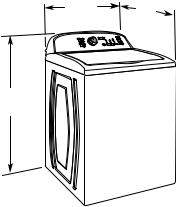
LOCATION REQUIREMENTS
Select proper location for your washer to improve performance and minimize noise and possible “washer walk.” Install your washer in a basement, laundry room, closet, or recessed area.
27.5" |
27" |
(699 mm) |
(686 mm) |
44" (1118 mm)
You will need:
■■ A water heater set to deliver 120°F (49°C) water to the washer.
■■ A grounded electrical outlet located within 4 ft. (1.2 m) of where the power cord is attached to the back of the washer. See “Electrical Requirements.”
■■ Hot and cold water faucets located within 3 ft. (900 mm) of the hot and cold water fill valves, and water pressure of
20–100 psi (138–690 kPa) for best performance.
■■ Level floor with maximum slope of 1" (25 mm) under entire washer. Installing the washer on carpet is not recommended.
■■ A sturdy floor to support the washer weight (washer, water, and load) of 315 lbs (143 kg).
IMPORTANT: Do not operate, install, or store washer where it will be exposed to water, weather, or at temperatures below 32° F (0° C). Some water can remain in washer and can cause damage in low temperatures. See your “Use and Care Guide” for information on winterizing.
Proper installation is your responsibility.
4

Spacing for recessed area or closet installation
All dimensions show recommended spacing allowed, with tested spacing of 0" (0 mm) clearance on sides.
■■ Additional spacing should be considered for ease of installation and servicing.
■■ Additional clearances might be required for wall, door, and floor moldings.
■■ Additional spacing should be considered on all sides of the washer to reduce noise transfer.
■■ For closet installation, with a door, minimum ventilation openings in the top and bottom of the door are required. Louvered doors with equivalent ventilation openings are acceptable.
■■ Companion appliance spacing should also be considered.
3"* (76 mm)
14" max.* |
48 in.2 * |
(356 mm) |
(310 cm2) |
|
17"* |
|
(432 mm) |
|
|
24 in.2 * |
5"* |
|
(155 cm2) |
(126 mm) |
|
|
|
1" |
3"* |
1" |
(25 mm) |
|
(25 mm) |
|
(76 mm) |
* Required spacing
DRAIN SYSTEM
Drain system can be installed using a floor drain, wall standpipe, floor standpipe, or laundry tub. Select method you need.
Floor standpipe drain system
|
39" |
4.5" |
(990 mm) |
(114 mm) |
|
Minimum diameter for a standpipe drain: 2" (51 mm). Minimum carry-away capacity: 17 gal. (64 L) per minute. Top of standpipe must be at least 39" (990 mm) high; install no higher than
96" (2.44 m) from bottom of washer. If you must install higher than 96" (2.44 m), you will need a sump pump system.
Wall standpipe drain system
4.5" (114 mm)
See requirements for floor standpipe drain system.
Floor drain system
Floor drain system requires a Siphon Break Kit (Part Number 285834), 2 Connector Kits (Part Number 285835), and an Extension Drain Hose (Part Number 285863) that may be purchased separately. To order, please see toll-free phone numbers in your “Use and Care Guide.” Minimum siphon break: 28" (710 mm) from bottom of washer. (Additional hoses may be needed.)
Laundry tub drain system
4.5" (114 mm)
39"0 (762990 mm)
Minimum capacity: 20 gal. (76 L). Top of laundry tub must be at least 39" (990 mm) above floor; install no higher than
96" (2.44 m) from bottom of washer.
IMPORTANT: To avoid siphoning, no more than 4.5" (114 mm) of drain hose should be inside standpipe or below the top of wash tub. Secure drain hose with cable tie.
5

ELECTRICAL REQUIREMENTS
■■ A 120 volt, 60 Hz., AC only, 15or 20-amp, fused electrical supply is required. A time-delay fuse or circuit breaker on a separate circuit serving only this washer is recommended.
■■ This washer is equipped with a power supply cord having a 3-prong grounding plug.
■■ To minimize possible shock hazard, the cord must be plugged into a mating, 3-prong, grounding-type outlet, grounded in accordance with local codes and ordinances. If a mating outlet is not available, it is the personal responsibility and obligation of the customer to have the properly grounded outlet installed by a qualified electrician.
■■ If codes permit and a separate ground wire is used, it is recommended that a qualified electrician determine that the ground path is adequate.
■■ Do not ground to a gas pipe.
■■ Check with a qualified electrician if you are not sure the washer is properly grounded.
■■ Do not have a fuse in the neutral or ground circuit.
6

INSTALLATION
INSTRUCTIONS
Before you start: remove shipping materials.
It is necessary to remove all shipping materials for proper operation and to avoid excessive noise from washer.
NOTE: To avoid floor damage during installation, set the washer onto cardboard before moving across the floor.
IMPORTANT:
■■ Be sure the foam shipping base has been removed from the bottom of the washer as directed in the “Remove Shipping Base and Packing Ring” section.
■■ If foam shipping base has not been removed, be sure lid is secured with tape before laying washer on its back.
■■ Removing the foam shipping base is necessary for proper operation.
REMOVE SHIPPING BASE
AND PACKING RING
1. Remove shipping base and packing ring |
Place cardboard supports from shipping carton on floor behind washer for support. Secure the lid with tape. Using two or more people, tip the washer onto its back and place on cardboard supports. Remove foam shipping base. Then, set washer back upright, and remove the tape from the lid so that you can open the lid and remove the foam packing ring from the washer tub.
NOTE: Keep foam packing ring in case you need to move the washer in the future.
CONNECT DRAIN HOSE
IMPORTANT: Proper connection of the drain hose helps to avoid water leakage and damage to your floors. The drain hose is connected to your washer and is stored inside the washer cabinet.
1. Remove drain hose from washer cabinet |
Gently pull hose out of back of washer cabinet from top until end emerges.
IMPORTANT: Do not force excess drain hose back into rear of washer.
2. Connect drain hose form
For a laundry tub or standpipe drain, connect the drain hose form. For a floor drain, do not install drain hose form. You may need alternate parts with separate directions. See “Tools and Parts” to determine what you may need.
Feed hose into one end of form. Bend hose and feed through other side, anchoring form on smooth sections of hose. The hose must extend 4.5" (114 mm) beyond the form.
7
3. Place drain hose in standpipe |
4.5" |
(114 mm) |
Place hose into standpipe (shown in picture) or over side of laundry tub.
IMPORTANT: To keep drain water from going back into the washer:
Do not force excess drain hose into standpipe. Hose should be secure but loose enough to provide a gap for air.
Do not lay excess hose on the bottom of the laundry tub.
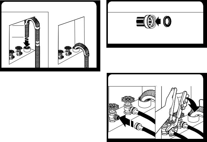
CONNECT INLET HOSES
1. Insert new flat washers
A B
A.Coupling
B.Washer
IMPORTANT: To avoid leaks, check that your water inlet hoses have flat washers at both ends. Washer must be connected to water faucets with new inlet hoses with flat washers (not provided). Do not use old hoses. Do not use hoses without washers.
2. Connect inlet hoses to water faucets |
Make sure the washer basket is empty. Attach the hose labeled hot to hot water faucet. Screw on coupling by hand until it is seated on washer. Use pliers to tighten couplings an additional two-thirds turn. Repeat this step with the hose labeled cold for the cold water faucet. Both hoses must be connected for washer to work properly.
IMPORTANT: Do not overtighten or use tape or sealants on valve when attaching to faucets or washer. Damage can result.
HELPFUL TIP: Make note of which hose is connected to hot water to help in attaching hoses to washer correctly.
8
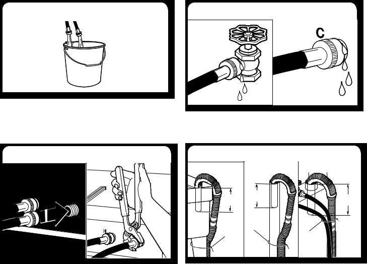
3. Clear water lines |
5. Check for leaks |
|
|
Run water for a few seconds through hoses into a laundry tub, drainpipe, or bucket to avoid clogs. Water should run until clear. Check the temperature of the water to make sure that the hot water hose is connected to the hot water faucet and the cold water hose is connected to the cold water faucet.
Turn on water faucets to check for leaks from faucet and at washer connection. A small amount of water may enter washer. You will drain this in a later step.
4. Connect inlet hoses to washer |
Attach hot water hose to hot water inlet valve. Screw coupling by hand until it is snug. Use pliers to tighten couplings an additional two-thirds turn. Repeat with cold water inlet valve. Both hoses must be connected for washer to work properly.
IMPORTANT: Do not overtighten or use tape or sealants on valve when attaching to faucets or washer. Damage can result.
NOTE: To reduce risk of hose failure, replace the hoses every 5 years. Record hose installation or replacement dates for future reference.
Periodically inspect and replace hoses if bulges, kinks, cuts, wear, or leaks are found.
6. Secure drain hose |
|
|
Laundry Tub |
Standpipe |
Wall |
4.5" |
4.5" |
4.5" |
(114 mm) |
||
(114 mm) |
|
(114 mm) |
|
A |
A |
A |
|
|
Secure drain hose to laundry tub leg, drain standpipe, or inlet hoses for wall standpipe with cable tie (A). This will help reduce the chance of drain water splashing on the floor.
9
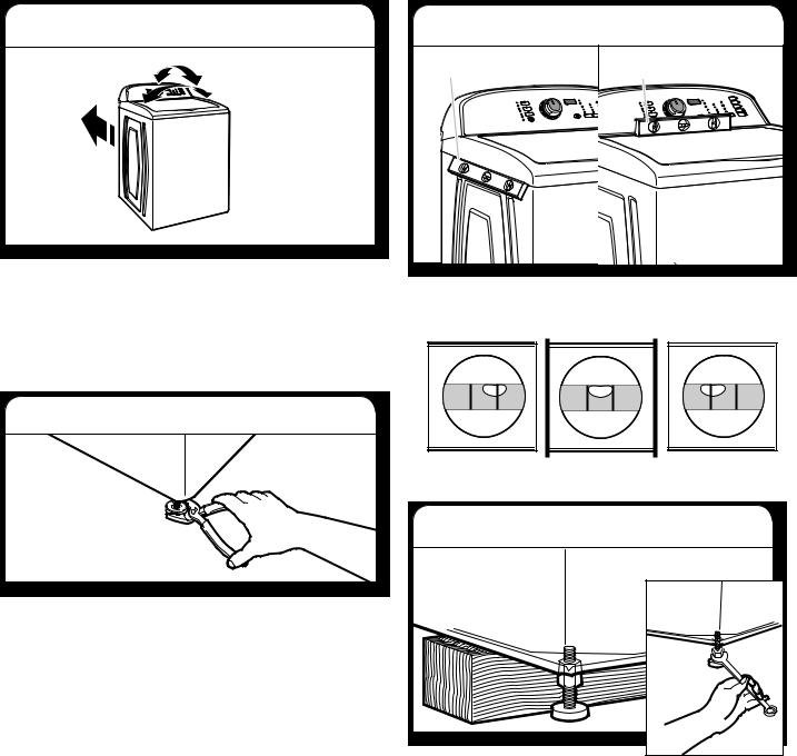
LEVEL WASHER
IMPORTANT: Leveling your washer properly reduces excess noise and vibration.
1. Move washer to final location
Move the washer to its final location. Rock the washer back and forth to check whether all four feet are stable and in firm contact with the floor. If the washer rocks, your model may be one that comes with 3 feet preset at the factory. It will be necessary to adjust the right front foot to level the washer. If all 4 feet were preset at the factory, minor adjustments may be needed to level the washer on your floor.
2. Adjust front leveling foot
3. Check levelness of washer |
|
Placelevellevelherehere |
Placelevellevelherehere |
Check the levelness of the washer. First, place a level on the lid near the console. Then place the level on the side of the washer in the crease between the top of the washer and the cabinet.
For washers with an adjustable right front foot, lower the right front foot until it contacts the floor. Using pliers, rotate the foot up to an additional 1 1/2 turns.
Not Level |
LEVEL |
Not Level |
4. Adjust levelness of washer |
|
|
If the washer is not level, move the washer out slightly, tip back
and prop up the front of the washer with a wood block. Adjust the right front foot by loosening the locknut with a 9/16" or 14 mm open-end wrench, then twisting the foot up or down as needed. After the washer is level, make sure all 4 feet are in firm contact with the floor by gently rocking it back and forth and side to side. Adjust the feet if necessary, then using the
wrench again, turn the locknuts counterclockwise on the foot to tighten to the washer cabinet.
HELPFUL TIP: You may have to adjust the back feet to level the washer. If you are installing the washer in a tight or hard-to- reach area, you may have to move the washer out to reach the feet comfortably. You may wish to lock the back feet before moving the washer back into place.
IMPORTANT: If the locknuts are not tight against the washer cabinet, the washer may vibrate.
10
 Loading...