


10689489993
Kenmore 10689489993, 10689483995, 10689483994, 10689483993, 10689482995 Owner’s Manual
...
Ice Maker
F_brica de hielo
_' '_ _....... _i_::_ " '__:_'_"_ " F_'_'_ _'_"<;;_''_''_"_
Machine _ glagons
®
Sears Roebuck and Co., Hoffman Estates, IL 60179 U.S.A. www.sears.com
2217243 Sears Canada, Inc., Toronto, Ontario, Canada M5B 2B8 www.sears.ca
TABLEOF CONTENTS
WARRANTY
WARRANTY ..................................................................................... 2
ICE MAKER SAFETY ...................................................................... 3
ICE MAKER INSTALLATION ......................................................... 4
Unpacking .................................................................................... 4
Location Requirements ................................................................ 4
Electrical Requirements ................................................................ 4
Leveling ......................................................................................... 5
Water Supply Connection ............................................................ 5
Reversing the Door Swing ............................................................ 7
Normal Sounds ............................................................................. 8
ICE MAKER USE ............................................................................. 8
How Your Ice Maker Works ......................................................... 8
Using the Controls ........................................................................ 9
ICE MAKER CARE .......................................................................... 9
Cleaning ........................................................................................ 9
Vacation and Moving Care ........................................................ 11
TROUBLESHOOTING .................................................................. 12
FULL ONE-YEAR WARRANTY ON ICE MAKER
For one year from the date of purchase, when this ice maker is
operated and maintained according to instructions attached to or
furnished with the product, Sears will repair this ice maker, free of
charge, if defective in material or workmanship.
LIMITED ONE-YEAR WARRANTY ON ICE MAKER
For one year from the date of purchase, when this ice maker is
used for commercial use and is operated and maintained
according to instructions attached to or furnished with the ice
maker, Sears will provide, free of charge, replacement parts for
any parts defective in materials or workmanship. You pay for
labor.
FULL FIVE-YEAR WARRANTY ON SEALED REFRIGERATION
SYSTEM
For five years from the date of purchase, when this ice maker is
operated and maintained according to instructions attached to or
furnished with the ice maker, Sears will repair the sealed system
(consisting of: refrigerant, connecting tubing, and compressor
motor), free of charge, if defective in materials or workmanship.
WARRANTY SERVICE IS AVAILABLE BY CONTACTING THE
NEAREST SEARS SERVICE CENTER IN THE UNITED STATES
OR CANADA.
This warranty applies only while this product is in use in the
United States or Canada. This warranty gives you specific legal
rights, and you may also have other rights which vary from state
to state or province to province.
Warranty terms may vary in Canada. Contact your local Sears
Service Center for complete details.
Sears, Roebuck and Co.
D/817WA, Hoffman Estates, IL 60179
Sears Canada, Inc., Toronto, Ontario, Canada M5B 2B8
In the space below, record your complete model number, serial
number, and purchase date. You can find this information on the
model and serial number label.
Have this information available to help you obtain assistance or
service more quickly whenever you contact Sears concerning
your ice maker.
Model number
Serial number
Purchase date
Save these instructions and your sales receipt for future
reference.
ICE MAKER SAFETY
Your safety and the safety of others are very important.
We have provided many important safety messages in this manual and on your appliance. Always read and obey all
safety messages.
This symbol alerts you to potential hazards that can kill or hurt you and others.
All safety messages will follow the safety alert symbol and either the word "DANGER" or
This is the safety alert symbol.
"WARNING." These words mean:
You can be killed or seriously injured if you don't
immediately follow instructions.
You can be killed or seriously injured if you don't
follow instructions.
All safety messages willtell you what the potential hazard is, tell you how to reduce the chance of injury, and tell you
what can happen if the instructions are not followed.
IMPORTANT SAFETY INSTRUCTIONS
WARNING: To reduce the risk of fire, electric shock, or injury when using your ice maker, follow these basic
precautions:
• Plug into a grounded 3 prong outlet.
• Do not remove ground prong.
• Do not use an adapter.
• Do not use an extension cord.
• Disconnect power before cleaning.
• Disconnect power before servicing.
• Replace all panels before operating.
• Use two or more people to move and install ice maker.
SAVE THESE INSTRUCTIONS
ICE MAKER
INSTALLATION
Excessive Weight Hazard
Use two or more people to move and install
ice maker.
Failure to do so can result in back or other injury.
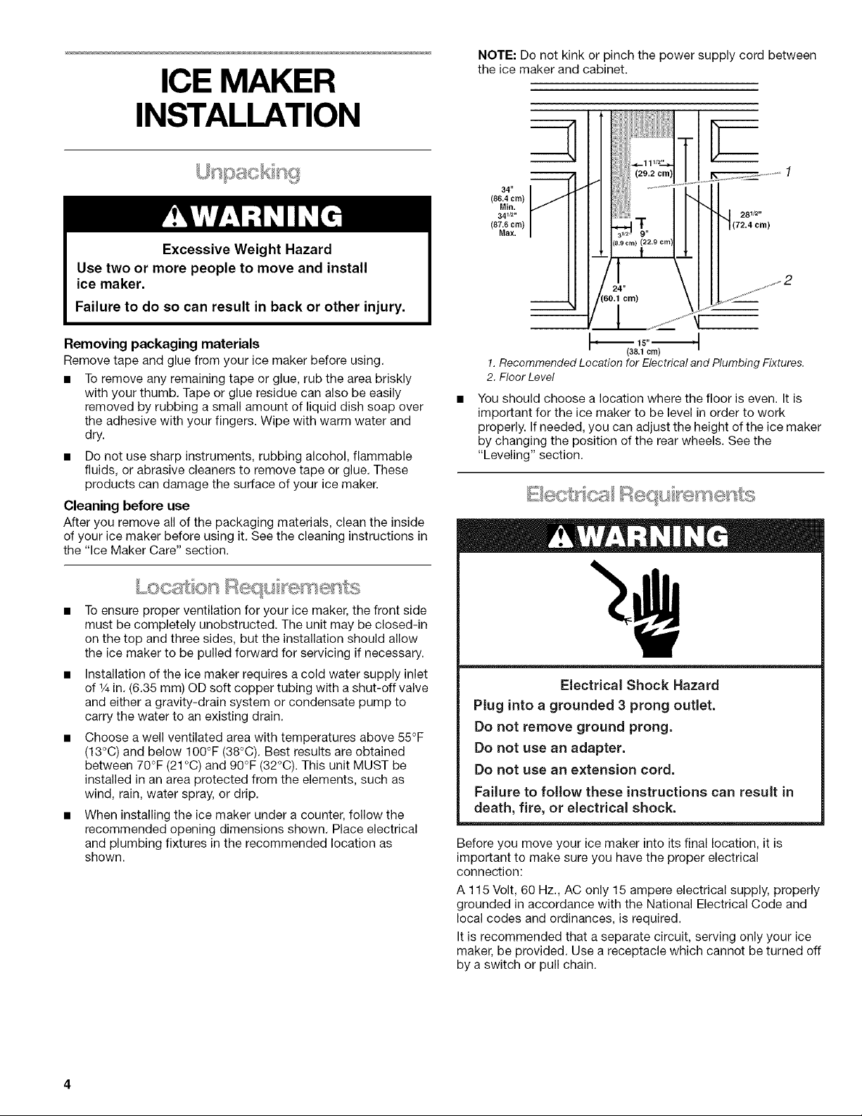
NOTE: Do not kink or pinch the power supply cord between
the ice maker and cabinet.
34"
(86.4 cm)
Min.
341/2"
(87.6 cm)
Max.
281/2 ,,
(72.4 cm)
Removing packaging materials
Remove tape and glue from your ice maker before using.
• To remove any remaining tape or glue, rub the area briskly
with your thumb. Tape or glue residue can also be easily
removed by rubbing a small amount of liquid dish soap over
the adhesive with your fingers. Wipe with warm water and
dry.
• Do not use sharp instruments, rubbing alcohol, flammable
fluids, or abrasive cleaners to remove tape or glue. These
products can damage the surface of your ice maker.
Cleaning before use
After you remove all of the packaging materials, clean the inside
of your ice maker before using it. See the cleaning instructions in
the "Ice Maker Care" section.
To ensure proper ventilation for your ice maker, the front side
must be completely unobstructed. The unit may be closed-in
on the top and three sides, but the installation should allow
the ice maker to be pulled forward for servicing if necessary.
Installation of the ice maker requires a cold water supply inlet
of % in. (6.35 mm) OD soft copper tubing with a shut-off valve
and either a gravity-drain system or condensate pump to
carry the water to an existing drain.
Choose a well ventilated area with temperatures above 55°F
(13°C) and below 100°F (38°C). Best results are obtained
between 70°F (21 °C) and 90°F (32°C). This unit MUST be
installed in an area protected from the elements, such as
wind, rain, water spray, or drip.
When installing the ice maker under a counter, follow the
recommended opening dimensions shown. Place electrical
and plumbing fixtures in the recommended location as
shown.
1. Recommended Location for Electrical and Plumbing Fixtures.
(38.1 crn)
2. Floor Level
You should choose a location where the floor is even. It is
important for the ice maker to be level in order to work
properly. If needed, you can adjust the height of the ice maker
by changing the position of the rear wheels. See the
"Leveling" section.
_,_._, ..............._@ ...........
Electrical Shock Hazard
Plug into a grounded 3 prong outlet.
Do not remove ground prong.
Do not use an adapter.
Do not use an extension cord.
Failure to follow these instructions can result in
death, fire, or electrical shock.
Before you move your ice maker into its final location, it is
important to make sure you have the proper electrical
connection:
A 115 Volt, 60 Hz., AC only 15 ampere electrical supply, properly
grounded in accordance with the National Electrical Code and
local codes and ordinances, is required.
It is recommended that a separate circuit, serving only your ice
maker, be provided. Use a receptacle which cannot be turned off
by a switch or pull chain.
Recommended grounding method
For your personal safety, this appliance must be grounded. This
appliance is equipped with a power supply cord having a 3 prong
grounding plug. To minimize possible shock hazard, the cord
must be plugged into a mating, 3 prong, grounding-type wall
receptacle, grounded in accordance with the National Electrical
Code and local codes and ordinances. If a mating wall receptacle
is not available, itis the personal responsibility of the customer to
have a properly grounded, 3 prong wall receptacle installed by a
qualified electrician.
It is important for the ice maker to be level in order to work
properly. Depending upon where you install the ice maker, you
may need to make several adjustments to level it.
Tools required
• Carpenter's level
• Adjustable wrench
• 1/4in. socket wrench
Undercounter installation
If you are installing the ice maker under a countertop, then you
may need to adjust the height of the ice maker. The adjustable
rear wheels are preset to position 1 for a cabinet opening height
of 34 in. (86.4 cm).
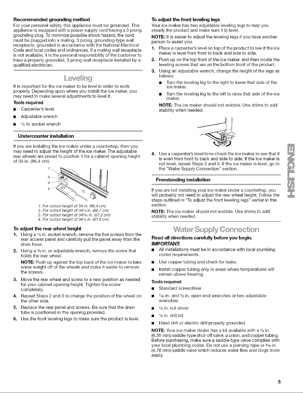
To adjust the front leveling legs
Your ice maker has two adjustable leveling legs to help you
steady the product and make sure it is level.
NOTE: It is easier to adjust the leveling legs if you have another
person to assist you.
1. Place a carpenter's level on top of the product to see if the ice
maker is level from front to back and side to side.
2. Push up on the top front of the ice maker, and then locate the
leveling screws that are on the bottom front of the product.
3. Using an adjustable wrench, change the height of the legs as
follows:
• Turn the leveling leg to the right to lower that side of the
ice maker.
• Turn the leveling leg to the left to raise that side of the ice
maker.
NOTE: The ice maker should not wobble. Use shims to add
stability when needed.
4.
Use a carpenter's level to re-check the ice maker to see that it
is even from front to back and side to side. If the ice maker is
not level, repeat Steps 2 and 3. If the ice maker is level, go to
the "Water Supply Connection" section.
!. For cutout height of 34 in. (86.4 cm)
2. For cutout height of 34_A in. (86. 7 cm)
3. For cutout height of 345/_6in. (87.2 cm)
4. For cutout height of 34V2 in. (87.6 cm)
To adjust the rear wheel height
1. Using a 1/4in. socket wrench, remove the five screws from the
rear access panel and carefully pull the panel away from the
drain hose.
2. Using a % in. or adjustable wrench, remove the screw that
holds the rear wheel.
NOTE: Push up against the top back of the ice maker to take
some weight off of the wheels and make it easier to remove
the screws.
3. Move the rear wheel and screw to a new position as needed
for your cabinet opening height. Tighten the screw
completely.
4. Repeat Steps 2 and 3 to change the position of the wheel on
the other side.
5. Replace the rear panel and screws. Be sure that the drain
tube is positioned in the opening provided.
6. Use the front leveling legs to make sure the product is level.
If you are not installing your ice maker under a countertop, you
Freestanding installation
will probably not need to adjust the rear wheel height. Follow the
steps outlined in "To adjust the front leveling legs" earlier in this
section.
NOTE: The ice maker should not wobble. Use shims to add
stability when needed.
Read all directions carefully before you begin.
IMPORTANT:
• All installations must be in accordance with local plumbing
codes requirements.
• Use copper tubing and check for leaks.
• Install copper tubing only in areas where temperatures will
remain above freezing.
Tools required
• Standard screwdriver
• 7/16in. and 1/2in. open-end wrenches or two adjustable
wrenches
• 1/4in. nut driver
• 1/4in. drill bit
• Hand drill or electric drill properly grounded
NOTE: Your ice maker dealer has a kit available with a 1/4in.
(6.35 mm) saddle-type shut-off valve, a union, and copper tubing.
Before purchasing, make sure a saddle-type valve complies with
your local plumbing codes. Do not use a piercing-type or 3/16in.
(4.76 mm) saddle valve which reduces water flow and clogs more
easily.

Connecting the water line
1=
Turn off main water supply• Turn on nearest faucet long
enough to clear line of water•
2=
Find a 1/2in. (12.70 mm) to 11/4in. (3.18 cm) vertical cold water
pipe near the ice maker•
NOTE: Horizontal pipe will work, but the following procedure
must be followed: Drill on the top side of the pipe, not the
bottom• This will help keep water away from the drill• This
also keeps normal sediment from collecting in the valve.
3. Using a grounded drill, drill a 1/4in. (6.35 mm) hole in the cold
water pipe you have selected.
4. Fasten shut-off valve to cold water pipe with pipe clamp• Be
sure outlet end is solidly in the 1/4in. (6.35 mm) drilled hole in
the water pipe and that washer is under the pipe clamp.
Tighten packing nut. Tighten the pipe clamp screws carefully
and evenly so washer makes a watertight seal. Do not
overtighten the pipe clamp or you may crush cold water pipe
if it is soft copper tubing. Do not use a piercing-type or 3A6in.
(4.76 mm) saddle-type valve which reduces water flow and
clogs more easily•
5. Now you are ready to connect the copper tubing. Use 1/4in.
(6.35 mm) OD soft copper tubing for the cold water supply.
• Measure from the connection at the front of the ice maker
to the cold water pipe. Add 3 ft (91.4 cm) to ensure that
you have the proper length. This is the length of 1/4in.
(6.35 mm) OD soft copper tubing you need for the job. Be
sure both ends of the copper tubing are cut square.
• Slip compression sleeve and compression nut on copper
tubing as shown. Insert end of tubing into outlet end
squarely as far as it will go. Screw compression nut onto
outlet end with adjustable wrench. Do not overtighten.
................. 1
8 _ "J"" •.............. 2
*% ............. 3
REARVIEW
1
2
/
!. Drain Hose (Drain Pump models only)
2• Vent Hose (Drain Pump models only)
3. Water Supply Line
8=
Thread the nut onto the coupling on the end of the copper
tubing. Tighten the nut by hand. Then tighten it with a wrench
two more turns. Do not overtighten.
1 2 3 4
1.Line to ice maker
2. Nut (purchased)
9=
Remove the two screws in the lower access panel and the
two screws in the base grille area of the front panel support.
Pull forward to remove the lower access panel.
NOTE: To prevent rattling, be sure the copper tubing does not
touch the cabinet's side wall or other parts inside the cabinet.
FRONT VIEW
3 2
3. Ferrule (purchased)
4. Coupling (purchased)
3
1.Cold Water Pipe 5. Compression Nut
2. Pipe Clamp 6. Compression Sleeve
3. Copper Tubing 7.Shut-Off Valve
4• Coupling (purchased) 8. Packing Nut
6=
Place the free end of the tubing into a container or sink, and
turn on main water supply and flush out tubing until water is
clear. Turn off shut-off valve on the water pipe.
NOTE: Always drain the water line before making the final
connection to the inlet of the water valve to prevent possible
water valve malfunction.
7.
Bend the copper tubing to meet the water line inlet which is
located on the back of the ice maker cabinet as shown.
(30.9 cm)
F 123/6" ID,
i
(14,5 cm)
(18.6 cm)
5%"
(14.3 cm)
1. WaterPan Drain
2. Water Valve
10. Turn shut-off valve ON.
11. Check for leaks. Tighten any connections (including
connections at the valve) or nuts that leak.
12. Replace the lower access panel and screws.
Connecting the drain
Gravity drain system
Connect the ice maker drain to your drain in accordance with all
state and local codes and ordinances. If the ice maker is
provided with a gravity drain system, follow these guidelines
when installing drain lines. This will prevent water from flowing
back into the ice maker storage bin and potentially flowing onto
the floor causing water damage.
• Drain lines must have a minimum of % in. (15.88 mm) inside
diameter.
Drain lines must have a I in. drop per 48 in. (2.54 cm drop per
122 cm) of run or 1/4in. drop per 12 in. (6.35 mm per
30.48 cm) and must not have low points where water can
settle.
• The floor drains must be large enough to accommodate
drainage from all drains.
The ideal installation has a standpipe with a 11/2in. (3.81 cm)
to 2 in. (5.08 cm) PVC drain reducer installed directly below
the outlet of the drain tube as shown. You must maintain a
1 in. (2.54 cm) air gap between the drain pump hose and the
standpipe.
• It may be desirable to insulate the drain line thoroughly up to
the drain inlet.
After ensuring that the drain system is adequate, follow these
steps to properly place the ice maker:
f. Plug in ice maker or reconnect power.
2. Re-check the ice maker to be sure that it is level. See the
"Leveling" section.
3. Push the ice maker into position so that the ice maker drain
tube is positioned over the PVC drain reducer.
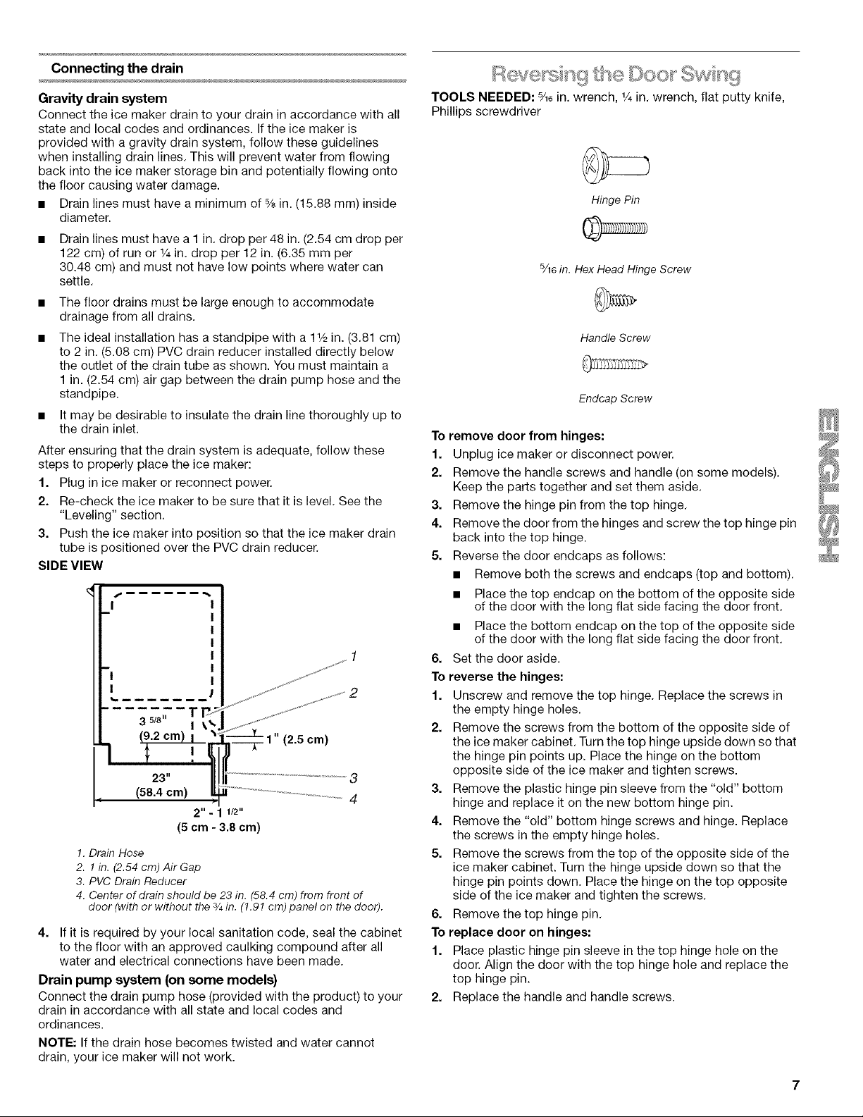
SIDE VIEW
I
23"
(58.4 cm)
3
4
2" - 1 1/2"
(5 cm - 3.8 cm)
!. Drain Hose
2. 1 in. (2.54 cm) Air Gap
3. PVC Drain Reducer
4. Center of drain should be 23 in. (58.4 cm) from front of
door (with or without the 3/4in. (1.91 cm) panel on the door).
4. If it is required by your local sanitation code, seal the cabinet
to the floor with an approved caulking compound after all
water and electrical connections have been made.
Drain pump system (on some models)
Connect the drain pump hose (provided with the product) to your
drain in accordance with all state and local codes and
ordinances.
NOTE: If the drain hose becomes twisted and water cannot
drain, your ice maker will not work.
t DOO ' t
TOOLS NEEDED: %e in. wrench, _/4in. wrench, flat putty knife,
Phillips screwdriver
Hinge Pin
5/16in. Hex Head Hinge Screw
Handle Screw
Endcap Screw
To remove door from hinges:
1. Unplug ice maker or disconnect power.
2. Remove the handle screws and handle (on some models).
Keep the parts together and set them aside.
3. Remove the hinge pin from the top hinge.
4. Remove the door from the hinges and screw the top hinge pin
back into the top hinge.
5. Reverse the door endcaps as follows:
• Remove both the screws and endcaps (top and bottom).
• Place the top endcap on the bottom of the opposite side
of the door with the long flat side facing the door front.
• Place the bottom endcap on the top of the opposite side
of the door with the long flat side facing the door front.
6. Set the door aside.
To reverse the hinges:
1. Unscrew and remove the top hinge. Replace the screws in
the empty hinge holes.
2. Remove the screws from the bottom of the opposite side of
the ice maker cabinet. Turn the top hinge upside down so that
the hinge pin points up. Place the hinge on the bottom
opposite side of the ice maker and tighten screws.
3. Remove the plastic hinge pin sleeve from the "old" bottom
hinge and replace it on the new bottom hinge pin.
4. Remove the "old" bottom hinge screws and hinge. Replace
the screws in the empty hinge holes.
5. Remove the screws from the top of the opposite side of the
ice maker cabinet. Turn the hinge upside down so that the
hinge pin points down. Place the hinge on the top opposite
side of the ice maker and tighten the screws.
6. Remove the top hinge pin.
To replace door on hinges:
1. Place plastic hinge pin sleeve in the top hinge hole on the
door. Align the door with the top hinge hole and replace the
top hinge pin.
2. Replace the handle and handle screws.
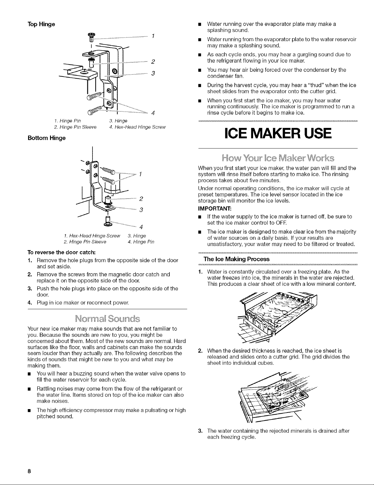
TopHinge
..........
2
3
4
!. Hinge Pin
2. Hinge Pin Sleeve
3. Hinge
4. Hex-Head Hinge Screw
Bottom Hinge
_ .........2
3
J
_ ...................................... 4
!. Hex-Head Hinge Screw
2. Hinge Pin Sleeve
To reverse the door catch:
1. Remove the hole plugs from the opposite side of the door
and set aside.
2. Remove the screws from the magnetic door catch and
replace it on the opposite side of the door.
3. Push the hole plugs into place on the opposite side of the
door.
4. Plug in ice maker or reconnect power.
3. Hinge
4. Hinge Pin
Water running over the evaporator plate may make a
splashing sound.
Water running from the evaporator plate to the water reservoir
may make a splashing sound.
As each cycle ends, you may hear a gurgling sound due to
the refrigerant flowing in your ice maker.
You may hear air being forced over the condenser by the
condenser fan.
During the harvest cycle, you may hear a "thud" when the ice
sheet slides from the evaporator onto the cutter grid.
When you first start the ice maker, you may hear water
running continuously. The ice maker is programmed to run a
rinse cycle before it begins to make ice.
ICE MAKER USE
When you first start your ice maker, the water pan will fill and the
system will rinse itself before starting to make ice. The rinsing
process takes about five minutes.
Under normal operating conditions, the ice maker will cycle at
preset temperatures. The ice level sensor located in the ice
storage bin will monitor the ice levels.
IMPORTANT:
• If the water supply to the ice maker is turned off, be sure to
set the ice maker control to OFR
• The ice maker is designed to make clear ice from the majority
of water sources on a daily basis. If your results are
unsatisfactory, your water may need to be filtered or treated.
The Ice Making Process
1. Water is constantly circulated over a freezing plate. As the
water freezes into ice, the minerals in the water are rejected.
This produces a clear sheet of ice with a low mineral content.
Your new ice maker may make sounds that are not familiar to
you. Because the sounds are new to you, you might be
concerned about them. Most of the new sounds are normal. Hard
surfaces like the floor, walls and cabinets can make the sounds
seem louder than they actually are. The following describes the
kinds of sounds that might be new to you and what may be
making them.
• You will hear a buzzing sound when the water valve opens to
fill the water reservoir for each cycle.
• Rattling noises may come from the flow of the refrigerant or
the water line. Items stored on top of the ice maker can also
make noises.
• The high efficiency compressor may make a pulsating or high
pitched sound.
2. When the desired thickness is reached, the ice sheet is
released and slides onto a cutter grid. The grid divides the
sheet into individual cubes.
3. The water containing the rejected minerals is drained after
each freezing cycle.
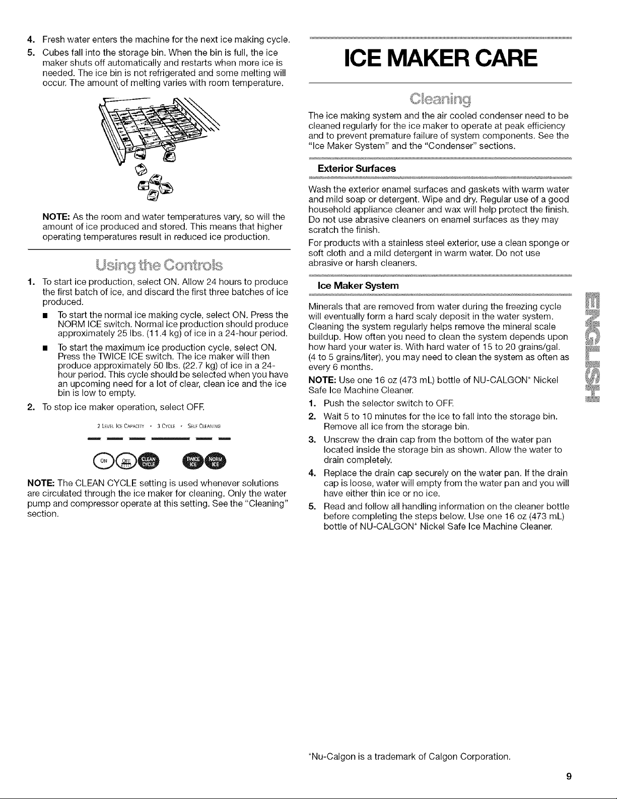
4,
Fresh water enters the machine for the next ice making cycle.
5.
Cubes fall into the storage bin. When the bin is full, the ice
maker shuts off automatically and restarts when more ice is
needed. The ice bin is not refrigerated and some melting will
occur. The amount of melting varies with room temperature.
NOTE: As the room and water temperatures vary, so will the
amount of ice produced and stored. This means that higher
operating temperatures result in reduced ice production.
ICE MAKER CARE
The ice making system and the air cooled condenser need to be
cleaned regularly for the ice maker to operate at peak efficiency
and to prevent premature failure of system components. See the
"Ice Maker System" and the "Condenser" sections.
Exterior Surfaces
Wash the exterior enamel surfaces and gaskets with warm water
and mild soap or detergent. Wipe and dry. Regular use of a good
household appliance cleaner and wax will help protect the finish.
Do not use abrasive cleaners on enamel surfaces as they may
scratch the finish.
For products with a stainless steel exterior, use a clean sponge or
soft cloth and a mild detergent in warm water. Do not use
abrasive or harsh cleaners.
1. Tostart ice production, select ON. Allow 24 hours to produce
the first batch of ice, and discard the first three batches of ice
produced.
• To start the normal ice making cycle, select ON. Press the
NORM ICE switch. Normal ice production should produce
approximately 25 Ibs. (11.4 kg) of ice in a 24-hour period.
• To start the maximum ice production cycle, select ON.
Press the TWICE ICE switch. The ice maker will then
produce approximately 50 Ibs. (22.7 kg) of ice in a 24-
hour period. This cycle should be selected when you have
an upcoming need for a lot of clear, clean ice and the ice
bin is low to empty.
2. To stop ice maker operation, select OFF.
2 LEVEE ICECAPACITY " 3 CYCLE " SELF CLEANING
@®@
NOTE: The CLEAN CYCLE setting is used whenever solutions
are circulated through the ice maker for cleaning. Only the water
pump and compressor operate at this setting. See the "Cleaning"
section.
Ice Maker System
Minerals that are removed from water during the freezing cycle
will eventually form a hard scaly deposit in the water system.
Cleaning the system regularly helps remove the mineral scale
buildup. How often you need to clean the system depends upon
how hard your water is. With hard water of 15 to 20 grains/gal.
(4 to 5 grains/liter), you may need to clean the system as often as
every 6 months.
NOTE: Use one 16 oz (473 mL) bottle of NU-CALGON* Nickel
Safe Ice Machine Cleaner.
1. Push the selector switch to OFF.
2. Wait 5 to 10 minutes for the ice to fall into the storage bin.
Remove all ice from the storage bin.
3. Unscrew the drain cap from the bottom of the water pan
located inside the storage bin as shown. Allow the water to
drain completely.
4. Replace the drain cap securely on the water pan. If the drain
cap is loose, water will empty from the water pan and you will
have either thin ice or no ice.
5. Read and follow all handling information on the cleaner bottle
before completing the steps below. Use one 16 oz (473 mL)
bottle of NU-CALGON* Nickel Safe Ice Machine Cleaner.
N
*Nu-Calgon is a trademark of Calgon Corporation.
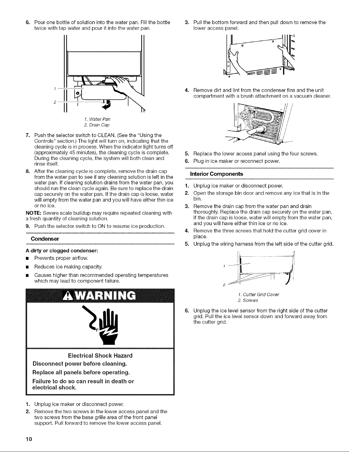
6. Pouronebottleofsolutionintothewaterpan.Fillthebottle 3. Pullthebottomforwardandthenpulldowntoremovethe
twicewithtapwaterandpouritintothewaterpan. loweraccesspanel.
4. Remove dirt and lint from the condenser fins and the unit
compartment with a brush attachment on a vacuum cleaner.
!. Water Pan
2. Drain Cap
7. Push the selector switch to CLEAN. (See the "Using the
Controls" section.) The light will turn on, indicating that the
cleaning cycle is in process. When the indicator light turns off
(approximately 45 minutes), the cleaning cycle is complete.
During the cleaning cycle, the system will both clean and
rinse itself.
8. After the cleaning cycle is complete, remove the drain cap
from the water pan to see if any cleaning solution is left in the
water pan. If cleaning solution drains from the water pan, you
should run the clean cycle again. Be sure to replace the drain
cap securely on the water pan. If the drain cap is loose, water
will empty from the water pan and you will have either thin ice
or no ice.
NOTE: Severe scale buildup may require repeated cleaning with
a fresh quantity of cleaning solution.
9. Push the selector switch to ON to resume ice production.
Condenser
A dirty or clogged condenser:
• Prevents proper airflow.
• Reduces ice making capacity.
• Causes higher than recommended operating temperatures
which may lead to component failure.
5. Replace the lower access panel using the four screws.
6. Plug in ice maker or reconnect power.
Interior Components
1. Unplug ice maker or disconnect power.
2. Open the storage bin door and remove any ice that is in the
bin.
3. Remove the drain cap from the water pan and drain
thoroughly. Replace the drain cap securely on the water pan.
If the drain cap is loose, water will empty from the water pan,
and you will have either thin ice or no ice.
4. Remove the three screws that hold the cutter grid cover in
place.
5. Unplug the wiring harness from the left side of the cutter grid.
Electrical Shock Hazard
Disconnect power before cleaning.
Replace all panels before operating.
Failure to do so can result in death or
electrical shock.
1.
Unplug ice maker or disconnect power.
2.
Remove the two screws in the lower access panel and the
two screws from the base grille area of the front panel
support. Pull forward to remove the lower access panel.
10
1. Cutter Grid Cover
2. Screws
6. Unplug the ice level sensor from the right side of the cutter
grid. Pull the ice level sensor down and forward away from
the cutter grid.
7.
Remove the right-hand and left-hand screws. Lift the cutter
grid up and out.
NOTE: Make sure the plastic spacer from the right-hand side
of the cutter grid bracket stays with the cutter grid.
1. Cutter Grid Harness
2. Screw
3. Cutter Grid
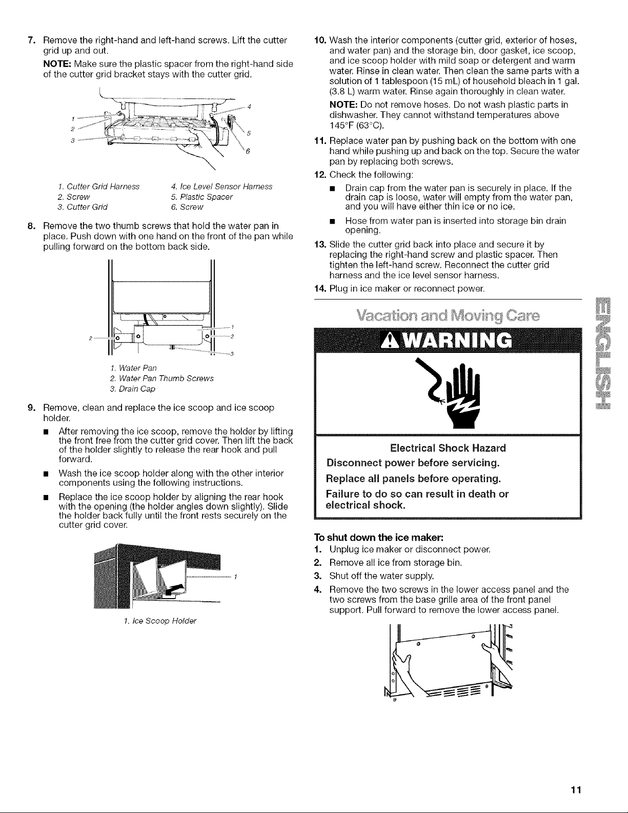
8.
Remove the two thumb screws that hold the water pan in
place. Push down with one hand on the front of the pan while
pulling forward on the bottom back side.
4. Ice Level Sensor Harness
5. Plastic Spacer
6. Screw
d
,kX o \ .......,
2 ¸--
1. Water Pan
2. Water Pan Thumb Screws
3. Drain Cap
9.
Remove, clean and replace the ice scoop and ice scoop
holder.
• After removing the ice scoop, remove the holder by lifting
the front free from the cutter grid cover. Then lift the back
of the holder slightly to release the rear hook and pull
forward.
Wash the ice scoop holder along with the other interior
components using the following instructions.
Replace the ice scoop holder by aligning the rear hook
with the opening (the holder angles down slightly). Slide
the holder back fully until the front rests securely on the
cutter grid cover.
!. Ice Scoop Holder
,..............id[
10.
Wash the interior components (cutter grid, exterior of hoses,
and water pan) and the storage bin, door gasket, ice scoop,
and ice scoop holder with mild soap or detergent and warm
water. Rinse in clean water. Then clean the same parts with a
solution of I tablespoon (15 mL) of household bleach in 1 gal.
(3.8 L) warm water. Rinse again thoroughly in clean water.
NOTE: Do not remove hoses. Do not wash plastic parts in
dishwasher. They cannot withstand temperatures above
145°F (63°C).
11. Replace water pan by pushing back on the bottom with one
hand while pushing up and back on the top. Secure the water
pan by replacing both screws.
12. Check the following:
• Drain cap from the water pan is securely in place. If the
drain cap is loose, water will empty from the water pan,
and you will have either thin ice or no ice.
• Hose from water pan is inserted into storage bin drain
opening.
13. Slide the cutter grid back into place and secure it by
replacing the right-hand screw and plastic spacer. Then
tighten the left-hand screw. Reconnect the cutter grid
harness and the ice level sensor harness.
14. Plug in ice maker or reconnect power.
Electrical Shock Hazard
Disconnect power before servicing.
Replace ail panels before operating.
Fai(ure to do so can result in death or
electrical shock.
To shut down the ice maker:
1. Unplug ice maker or disconnect power.
2. Remove all ice from storage bin.
3. Shut off the water supply.
4. Remove the two screws in the lower access panel and the
two screws from the base grille area of the front panel
support. Pull forward to remove the lower access panel.
F
11
 Loading...