


Z 1000 SX
Table of contents
 Loading...
Z1000
Z1000 ABS
Motorcycle
Service Manual

Quick Reference Guide
General Information 1 j
Periodic Maintenance 2 j
Fuel System (DFI) 3 j
Cooling System 4 j
Engine Top End 5 j
Clutch 6 j
Engine Lubrication System 7 j
Engine Removal/Installation 8 j
This quick reference guide will assist
you in locating a desired topic or procedure.
•Bend the pages back to match the
black tab of the desired chapter number with the black tab on the edge at
each table of contents page.
•Refer to the sectional table of contents
for the exact pages to locate the specific topic required.
Crankshaft/Transmission 9 j
Wheels/Tires 10 j
Final Drive 11 j
Brakes 12 j
Suspension 13 j
Steering 14 j
Frame 15 j
Electrical System 16 j
Appendix 17 j


Z1000
Z1000 ABS
Motorcycle
Service Manual
All rights reserved. No parts of this publication may be reproduced, stored in a retrieval system, or
transmitted i n any form or by any means, electronic mechanical photocopying, recording or otherwise,
without the prior written permission of Quality Assurance Division/Consumer Products & Machinery
Company/Kawasaki Heavy Industries, Ltd., Japan.
No liability can be accepted for any inaccuracies or omissions in this publication, although every possible
care has been taken to make it as complete and accurate as possible.
The right is reserved to make changes at any time without prior notice and without incurring an obligation
to make such changes to products manufactured previously. See your Motorcycle dealer for the latest
information on product improvements incorporated after this publication.
All information contained in this publication is based on the latest product information available at the time
of publication. Illustrations and photographs in this publication are intended for reference use only and may
not depict actual model component parts.
© 2007 Kawasaki Heavy Industries, Ltd. First Edition (1) : Feb. 13, 2007 (M)

LIST OF ABBREVIATIONS
A ampere(s) lb pound(s)
ABDC after bottom dead center m meter(s)
AC alternating current min minute(s)
ATDC after top dead center
BBDC before bottom dead center
BDC
BTDC before top dead center psi pound(s) per square inch
°C degree(s) Celsius r revolution
DC direct current rpm revolution(s) per minute
F farad(s) TDC top dead center
°F degree(s) Fahrenheit TIR total indicator reading
ft foot, feet V volt(s)
g gram(s) W watt(s)
h hour(s) Ω ohm(s)
L liter(s)
bottom dead center
N
Pa
PS
newton(s)
pascal(s)
horsepower
COUNTRY AND AREA CODES
A
T
AU Australia
CA Canada MY Malaysia
CAL California US United States
CH Switzerland WVTA Whole Vehicle Type Approval
DE Germany
A
ustria
F
R
GB
F
rance
United Kingdom

EMISSION CONTROL INFORMATION
To protect the environment in which we all live, Kawasaki has incorporated crankcase emission (1) and exhaust emission (2) control systems in compliance with applicable regulations of
the United States Environmental Protection Agency and California Air Resources Board. Additionally, Kawasaki has incorporated an evaporative emission control system (3) in compliance
with applicable regulations of the California Air Resources Board on vehicles sold in California
only.
1. Crankcase Emission Control System
Thissystemeliminatesthereleaseof crankcase vapors intothe atmosphere. Instead, thevapors
are routed through an oil separator to the inlet side of the engine. While the engine is operating,
the vapors are drawn into combustion chamber, where they are burned along with the fuel and air
supplied by the fuel injection system.
2. Exhaust Emission Control System
This system reduces the amount of pollutants discharged into the atmosphere by the exhaust
of this motorcycle. The fuel, ignition, and exhaust systems of this motorcycle have been carefully
designed and constructed to ensure an efficient engine with low exhaust pollutant levels.
The exhaust system of this model motorcycle manufactured primarily for sale in California in-
cludes a catalytic converter system.
3. Evaporative Emission Control System
Vapors caused by fuel evaporation in the fuel system are not vented into the atmosphere. In-
stead, fuel vapors are routed into the running engine to be burned, or stored in a canister when
the engine is stopped. Liquid fuel is caught by a vapor separator and returned to the fuel tank.
The Clean Air Act, which is the Federal law covering motor vehicle pollution, contains what is
commonly referred to as the Act’s “tampering provisions”.
“Sec. 203(a) The following acts and the causing thereof are prohibited.
(3)(A) for any person to remove or render inoperative any device or element of design installed
on or in a motor vehicle or motor vehicle engine in compliance with regulations under this
title prior to its sale and delivery tothe ultimate purchaser, or for any manufacturer or dealer
knowingly to remove or render inoperative any such device or element of design after such
sale and delivery to the ultimate purchaser.
(3)(B) for any person engaged in the business of repairing, servicing, selling, leasing, or trading
motor vehicles or motor vehicle engines, or who operates a fleet of motor vehicles knowingly to remove or render inoperative any device or element of design installed on or in a
motor vehicle or motor vehicle engine in compliance with regulations under this title following its sale and delivery to the ultimate purchaser...”
NOTE
The phrase “remove or render inoperative any device or element of design” has been generally
○
interpreted as follows.
1. Tampering does not include the temporary removal or rendering inoperative of devices or elements of design in order to perform maintenance.
2. Tampering could include.
a.Maladjustment of vehicle components such that the emission standards are ex-
ceeded.
b.Use of replacement parts or accessories which adversely affect the performance
or durability of the motorcycle.
c.Addition of components or accessories thatresultinthe vehicle exceeding the stan-
dards.
d.Permanently removing, disconnecting, or rendering inoperative any component or
element of design of the emission control systems.
WE RECOMMEND THAT ALL DEALERS OBSERVE THESE PROVISIONS OF FEDERAL
LAW,THE VIOLATIONOF WHICH IS PUNISHABLE BY CIVIL PENALTIES NOT EXCEEDING
$10 000 PER VIOLATION.
TAMPERING WITH N OISE CONTROL SYSTEM PROHIBITED
Federal law prohibits the following acts or the causing thereof. (1) The removal or rendering
inoperativeby any person other than for purposes of maintenance, repair, or replacement, of any
device or element of design incorporated into any new vehicle for the purpose of noise control
prior to its sale or delivery to the ultimate purchaser or while it is in use, or (2) the use of the
vehicle after such device or element of design has been removed or rendered inoperative by
any person.
Among those acts presumed to constitute tampering are the acts listed below.
Replacement of the original exhaust system or muffler with a component not in compliance
•
with Federal regulations.
Removal of the muffler(s) or any internal portion of the muffler(s).
•
Removal of the air box or air box cover.
•
Modifications to the muffler(s) or air inlet system by cutting, drilling, or other means if such
•
modifications result in increased noise levels.
Foreword
This manual is designed primarily for use by
trained mechanics in a properly equipped shop.
However,it containsenough detail and basic informationto make it useful to theowner who desiresto perform his own basic maintenance and
repair work. A basic knowledge of mechanics,
the proper use of tools, and workshop procedures must be understood in order to carry out
maintenance and repair satisfactorily. Whenever the owner has insufficient experience or
doubts his ability to do the work, all adjustments, maintenance, and repair should be carried out only by qualified mechanics.
In order to perform the work efficiently and
to avoid costly mistakes, read the text, thoroughly familiarize yourself with the procedures
beforestarting work, and then do the work carefully in a clean area. Whenever special tools or
equipment are specified, do not use makeshift
tools or equipment. Precision measurements
can only be made if the proper instruments a re
used, and the use of substitute tools may adversely affect safe operation.
For the duration of the warranty period,
we recommend that all repairs and scheduled
maintenance be performed in accordance with
thisservice manual. Anyowner maintenance or
repair procedure not performed in accordance
with this manual may void the warranty.
To get the longest life out of your vehicle.
Follow the Periodic Maintenance Chart in the
•
Service Manual.
Be alert for problems and non-scheduled
•
maintenance.
Use proper tools and genuine Kawasaki Mo-
•
torcycle parts. Special tools, gauges, and
testers that are necessary when servicing
Kawasaki motorcycles are introduced by the
Service Manual. Genuine parts provided as
spare parts are listed in the Parts Catalog.
Follow the procedures in this manual care-
•
fully. Don’t take shortcuts.
Rememberto keepcomplete records ofmain-
•
tenance and repair with dates and any new
parts installed.
How to Use This Manual
In this manual, the product is divided into
its major systems and these systems make up
the manual’s chapters. The Quick Reference
Guide shows you all of the product’s system
and assists in locating their chapters. Each
chapter in turn has its own comprehensive Table of Contents.
For example, if you want ignition coil information, use the Quick Reference Guide to locate
the Electrical System chapter. Then, use the
Table of Contents on the first page of the chapter to find the Ignition Coil section.
Whenever you see these WARNING and
CAUTION symbols, heed their instructions!
Always follow safe operating and maintenance
practices.
WARNING
This warning symbol identifies special
instructions or procedures which, if not
correctly followed, could result in per-
sonal injury, or loss of life.
CAUTION
This caution symbol identifies special
instructions or procedures which, if not
strictly observed, could result in dam-
age to or destruction of equipment.
This manual contains four more symbols (in
additionto WARNINGandCAUTION) whichwill
help you distinguish different types of information.
NOTE
This note symbol indicates points of par-
○
ticular interest for more efficient and con-
venient operation.
Indicates a procedural step or work to be
•
done.
Indicates a procedural sub-step or how to do
○
the work of the procedural step it follows. It
also precedes the text of a NOTE.
Indicates a conditional step or what action to
takebased on the results ofthe test or inspec-
tion in the procedural step or sub-step it fol-
lows.
In most chapters an exploded view illustration
of the system components follows the Table of
Contents. In these illustrations you will find the
instructions indicating which parts require specified tightening torque, oil, grease or a locking
agent during assembly.


GENERAL INFORMATION 1-1
General Information
Table of Contents
Before Servicing..................................................................................................................... 1-2
Model Identification................................................................................................................. 1-7
General Specifications............................................................................................................ 1-10
Unit Conversion Table ............................................................................................................ 1-13
1
1-2 GENERAL INFORMATION
Before Servicing
Before starting to perform an inspection service or carry out a disassembly and reassembly operation on a motorcycle, read the precautions given below. To facilitate actual operations, notes, illustrations, photographs, cautions, and detailed descriptions have been included in each chapter wherever
necessary. This section explains the items that require particular attention during the removal and
reinstallation or disassembly and reassembly of general parts.
Especially note the following.
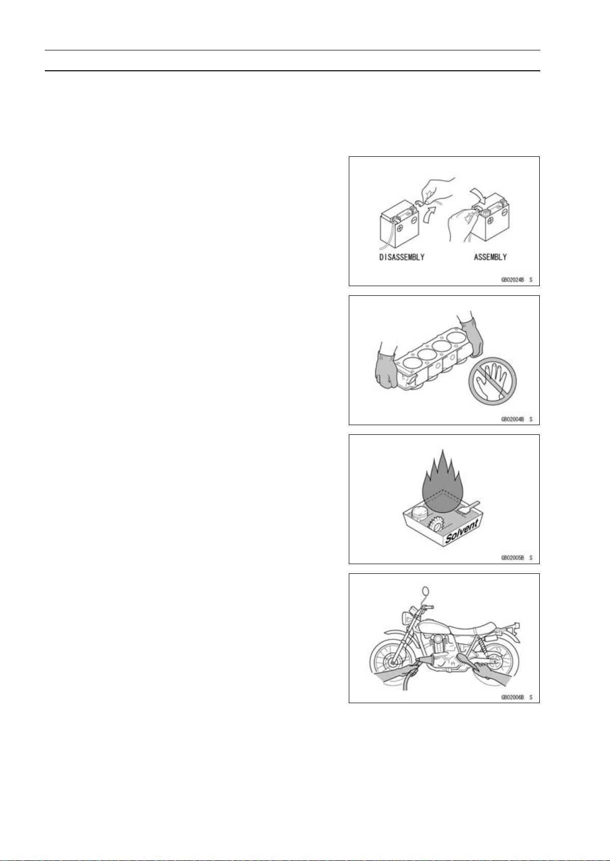
Battery Ground
Before completing any service on the motorcycle, disconnect the battery cables from the battery to prevent the engine from accidentally turning over. Disconnect the ground
cable (–) first and then the positive (+). When completed
with the service, first connect the positive (+) cable to the
positive (+) terminal of the battery then the negative (–) cable to the negative terminal.
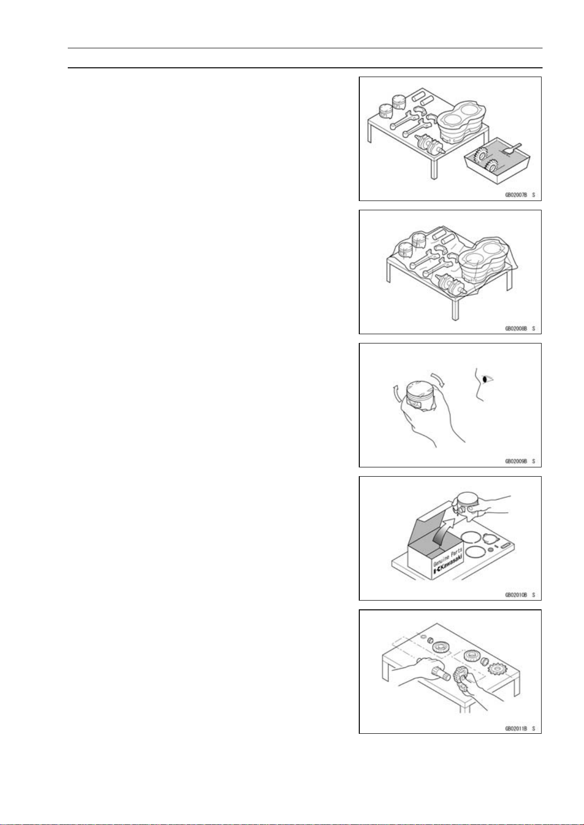
Edges of Parts
Lift large or heavy parts wearing gloves to prevent injury
from possible sharp edges on the parts.
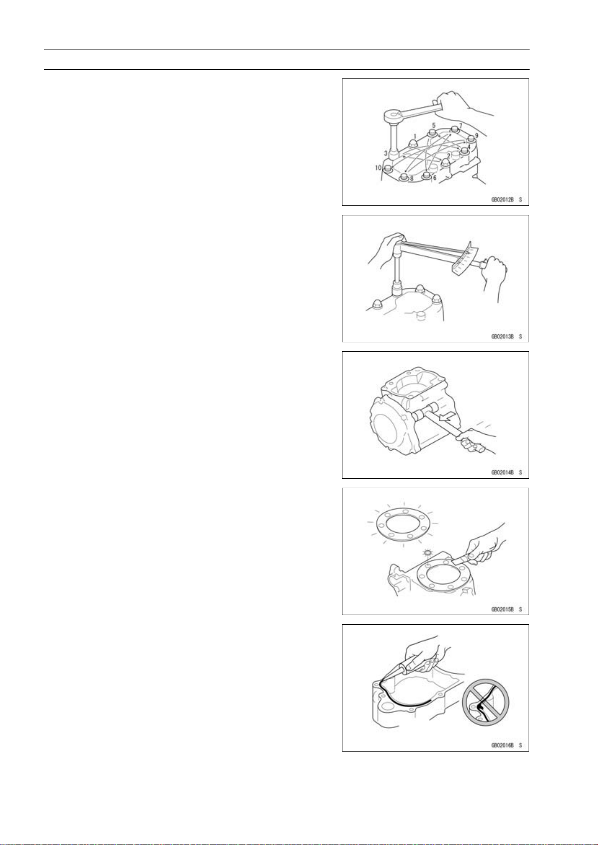
Solvent
Use a high-flush point solvent when cleaning parts. High
-flush point solvent should be used according to directions
of the solvent manufacturer.
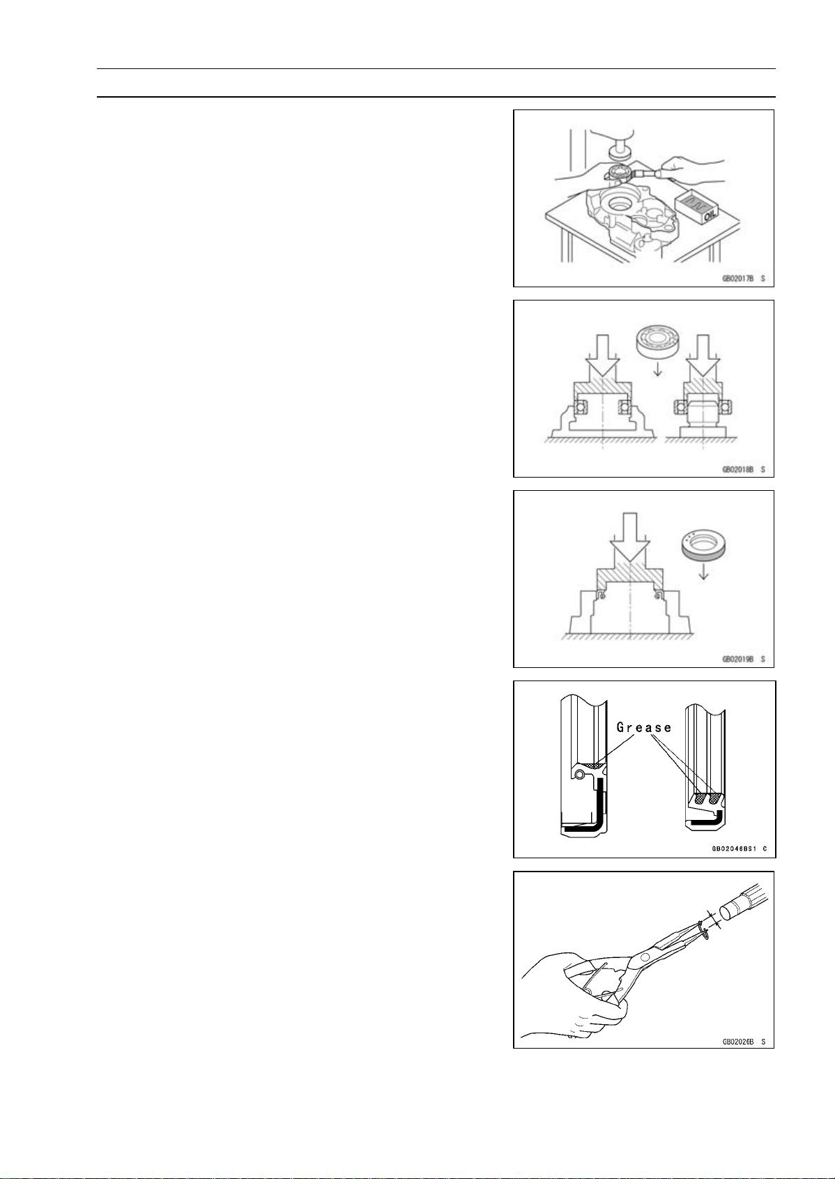
Cleaning Vehicle before Disassembly
Clean the vehicle thoroughly before disassembly. Dirt or
otherforeign materials entering into sealedareas during vehicle disassembly can cause excessive wear and decrease
performance of the vehicle.
Before Servicing
Arrangement and Cleaning of Removed Parts
Disassembled parts are easy to confuse. Arrange the
parts according to the order the parts were disassembled
and clean the parts in order prior to assembly.
Storage of Removed Parts
After all the parts including subassembly parts have been
cleaned, store the parts in a clean area. Put a clean cloth
or plastic sheet over the parts to protect from any foreign
materials that may collect before re-assembly.
GENERAL INFORMATION 1-3
Inspection
Reuse of worn or damaged parts may lead to serious accident. Visually inspect removedparts forcorrosion, discoloration, or otherdamage. Refer to the appropriate sections
of this manual for service limits on individual parts. Replace
the parts if any damage has been found or if the part is beyond its service limit.
Replacement Parts
Replacement parts must be KAWASAKI genuine or
recommended by KAWASAKI. Gaskets, O-rings, oil seals,
grease seals, circlips or cotter pins must be replaced with
new ones whenever disassembled.
Assembly Order
In most cases assembly order is the reverse of disassembly, however, if assembly order is provided in this Service
Manual, follow the procedures given.
1-4 GENERAL INFORMATION
Before Servicing
Tightening Sequence
Generally, when installing a part with several bolts, nuts,
or screws, start them all in their holes and tighten them to
a snug fit. Then tighten them according to the specified sequence to prevent case warpage or deformation which can
lead to malfunction. Conversely when loosening the bolts,
nuts, or screws, first loosen all of them by about a quarter turn and then remove them. If the specified tightening
sequence is not indicated, tighten the fasteners alternating
diagonally.
Tightening Torque
Incorrect torque applied to a bolt, nut, or screw may
lead to serious damage. Tighten fasteners to the specified
torque using a good quality torque wrench.
Force
Use common sense during disassembly and assembly,
excessive forcecan cause expensive or hard to repair damage. When necessary, remove screws that have a non
-permanent locking agent applied using an impact driver.
Use a plastic-faced mallet whenever tapping is necessary.
Gasket, O-ring
Hardening, shrinkage, or damage of both gaskets and
O-rings after disassembly can reduce sealing performance.
Remove old gaskets and clean the sealing surfaces thoroughly so that no gasket material or other material remains.
Install the new gaskets and replace the used O-rings when
re-assembling.
Liquid Gasket, Non-permanent Locking Agent
For applications that require Liquid Gasket or a
Non-permanent Locking Agent, clean the surfaces so
that no oil residue remains before applying liquid gasket or
non-permanent locking agent. Do not apply them excessively. Excessive application can clog oil passages and
cause serious damage.
Before Servicing
Press
For items such as bearings or oil seals that must be
pressed into place, apply small amount of oil to the contact area. Be sure to maintain proper alignment and use
smooth movements when installing.
Ball Bearing and Needle Bearing
Do not remove pressed ball or needle unless removal is
absolutely necessary. Replace with new ones whenever
removed. Press bearings with the manufacturer and size
marks facing out. Press the bearing into place by putting
pressure on the correct bearing race as shown.
Pressing the incorrect race can cause pressure between
the inner and outer race and result in bearing damage.
GENERAL INFORMATION 1-5
Oil Seal, Grease Seal
Donot removepressed oil orgrease sealsunless removal
is necessary. Replace with new ones whenever removed.
Press new oil seals with manufacture and size marks facing
out. Make sure the seal is aligned properly when installing.
Apply specified grease to the lip of seal before installing
the seal.
Circlips, Cotter Pins
Replace the circlips or cotter pins that were removed with
new ones. Take care not to open the clip excessively when
installing to prevent deformation.
1-6 GENERAL INFORMATION
Before Servicing
Lubrication
It is important to lubricate rotating or sliding parts during
assembly to minimize wear during initial operation. Lubrication points are called out throughout this manual, apply
the specific oil or grease as specified.
Direction of Engine Rotation
When rotating the crankshaft by hand, the free play
amount of rotating direction will affect the adjustment. Rotate the crankshaft to positive direction (clockwise viewed
from output side).
Electrical Wires
A two-color wire is identified first by the primary color and
then the stripe color. Unless instructed otherwise, electrical
wires must be connected to those of the same color.
Instrument
Use a meter that has enough accuracy for an accurate
measurement. Read the manufacture’s instructions thoroughly before using the meter. Incorrect values may lead
to improper adjustments.
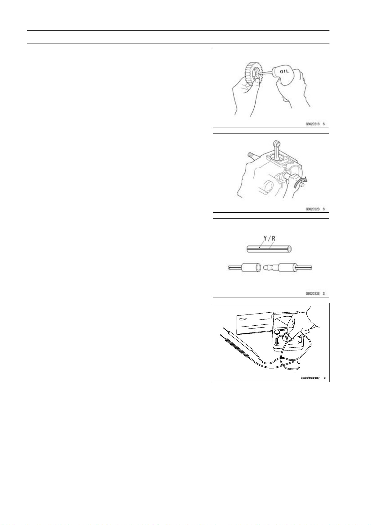
Model Identification
ZR1000B7F (United States and Canada) Left Side View
GENERAL INFORMATION 1-7
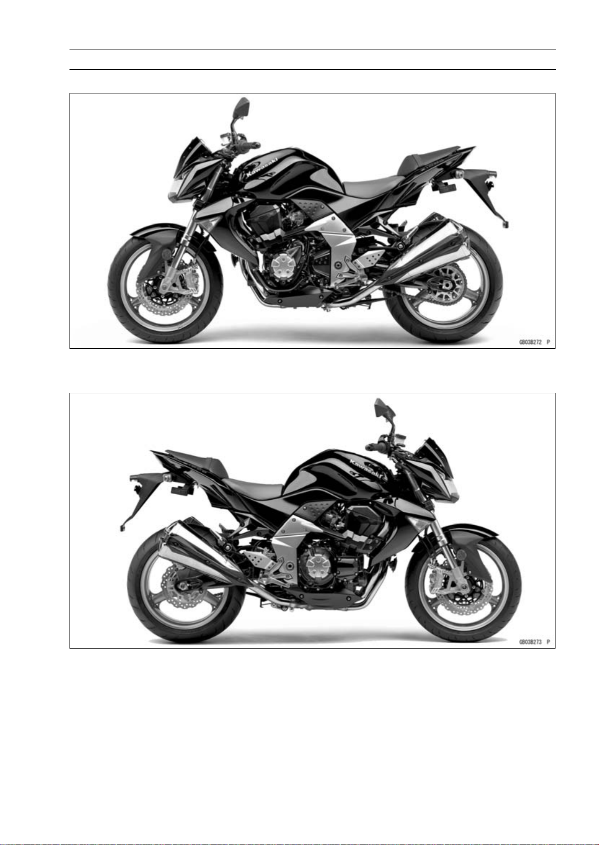
ZR1000B7F (United States and Canada) Right Side View
1-8 GENERAL INFORMATION
Model Identification
ZR1000B7F (Europe) Left Side View
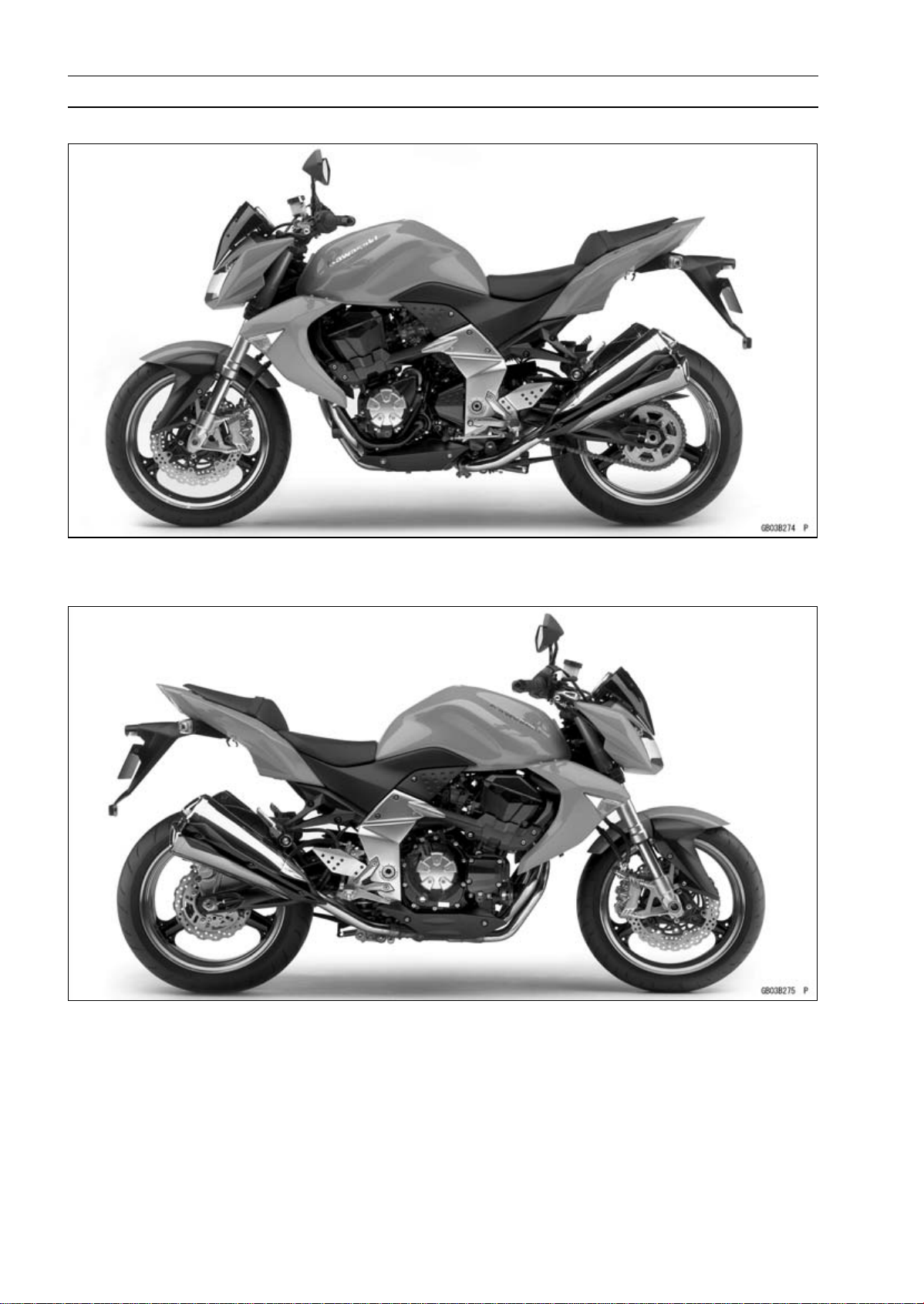
ZR1000B7F (Europe) Right Side View
Model Identification
ZR1000C7F Left Side View
GENERAL INFORMATION 1-9
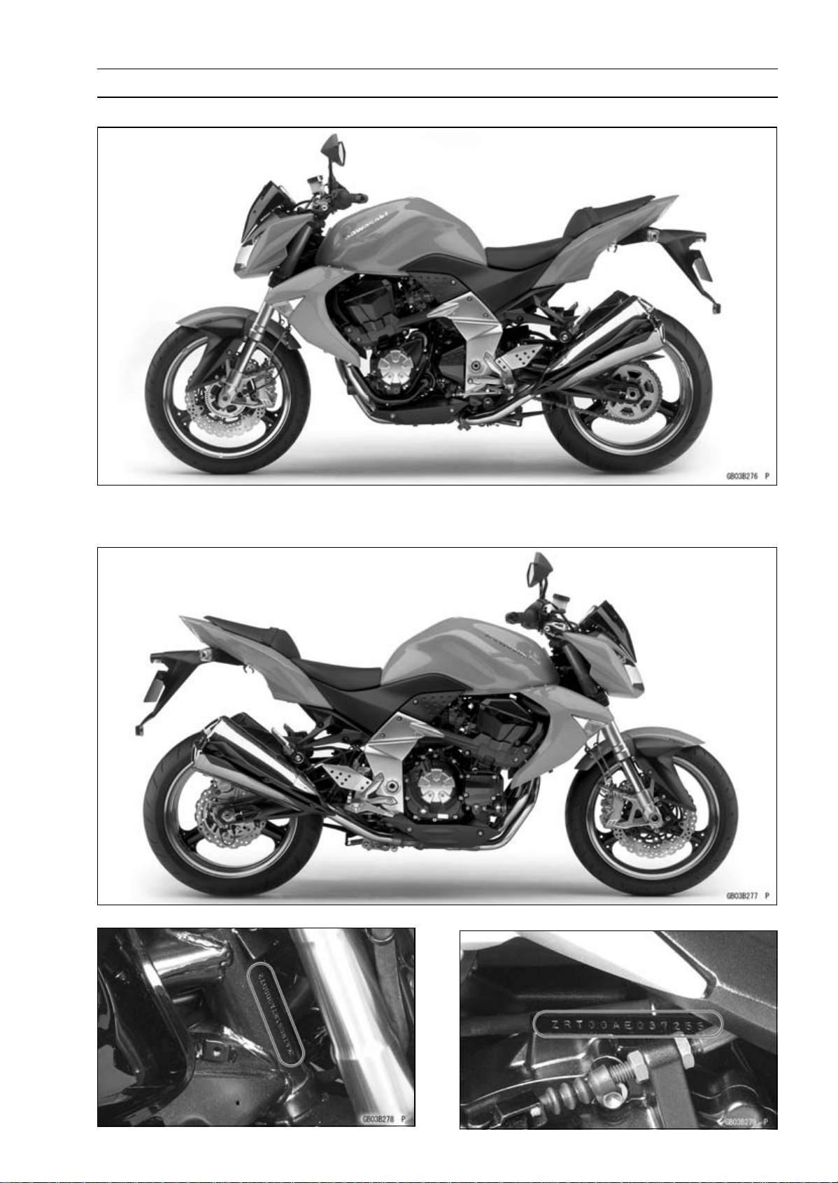
ZR1000C7F Right Side View
Frame Number Engine Number
1-10 GENERAL INFORMATION
General Specifications
Items ZR1000B7F, ZR1000C7F
Dimensions
Overall Length 2 090 mm (82.28 in.)
Overall Width 780 mm (30.71 in.)
Overall Height 1 065 mm (41.93 in.)
Wheelbase 1 445 mm (56.89 in.)
Road Clearance 160 mm (6.30 in.)
Seat Height 820 mm (32.28 in.)
Dry Mass:
ZR1000B7F 205 kg (452.0 lb)
ZR1000C7F 209 kg (460.8 lb)
Curb Mass:
Front:
ZR1000B7F 112 kg (247.0 lb)
ZR1000C7F 114 kg (251.4 lb)
Rear:
ZR1000B7F 116 kg (255.8 lb)
ZR1000C7F 118 kg (260.2 lb)
Fuel Tank Capacity 18.5 L (4.9 US gal.)
Performance
Minimum Turning Radius 3.0 m (9.8 ft)
Engine
Type 4-stroke, DOHC, 4-cylinder
Cooling System Liquid-cooled
Bore and Stroke 77.2 × 50.9 mm (3.04 × 2.00 in.)
Displacement 953 cm³ (58.15 cu in.)
Compression Ratio 11.2 : 1
Maximum Horsepower 92.0 kW (125 PS) @10 000 r/min (rpm)
(FR) 78.2 kW (106 PS) @9 000 r/min (rpm)
(CA),(CAL),(US)–––
Maximum Torque 98.7 N·m (10.1 kgf·m, 72.8 ft·lb) @8 200 r/min (rpm)
(FR) 92.4 N·m (9.4 kgf·m, 68.2 ft·lb) @7 700 r/min (rpm)
(CA),(CAL),(US)–––
Carburetion System FI (Fuel Injection) KEIHIN TTK36 × 4
Starting System Electric starter
Ignition System Battery and coil (transistorized)
Timing Advance Electronically advanced (digital igniter)
Ignition Timing From 10° BTDC @1 100 r/min (rpm) to 37.5° BTDC
@5 500 r/min (rpm)
Spark Plug NGK CR9EIA-9
Cylinder Numbering Method Left to right, 1-2-3-4
Firing Order
1-2-4-3

GENERAL INFORMATION 1-11
General Specifications
Items ZR1000B7F, ZR1000C7F
Valve Timing:
Inlet:
Open 38° BTDC
Close 58° ABDC
Duration 276°
Exhaust:
Open 51° BBDC
Close 25° ATDC
Duration 256°
Lubrication System Forced lubrication (wet sump)
Engine Oil:
Type
Viscosity SAE 10W-40
Capacity 3.8L(4.0USqt)
Drive Train
Primary Reduction System:
Type
Reduction Ratio 1.714 (84/49)
Clutch Type Wet multi disc
Transmission:
Type
Gear Ratios:
1st
2nd 1.882 (32/17)
3rd 1.556 (28/18)
4th 1.333 (28/21)
5th 1.200 (24/20)
6th 1.095 (23/21)
Final Drive System:
Type Chain drive
Reduction Ratio 2.667 (40/15)
Overall Drive Ratio 5.007 @Top gear
Frame
Type Tubular, diamond
Caster (Rake Angle) 24.5°
Trail 103 mm (4.06 in.)
Front Tire:
Type Tubeless
Size 120/70 ZR17 M/C (58W)
Rim Size 17 × 3.50
API SE, SF or SG
API SH, SJ or SL with JASO MA
Gear
6-speed, constant mesh, return shift
2.571 (36/14)

1-12 GENERAL INFORMATION
General Specifications
Items ZR1000B7F, ZR1000C7F
Rear Tire:
Type Tubeless
Size 190/50 ZR17 M/C (73W)
Rim Size 17 × 6.00
Front Suspension:
Type Telescopic fork
Wheel Travel 120 mm (4.72 in.)
Rear Suspension:
Type Swingarm (uni-trak)
Wheel Travel 150 mm (5.91 in.)
Brake Type:
Front Dual discs
Rear
Electrical Equipment
Battery 12 V 8 Ah
Headlight:
Type Semi-sealed beam
Bulb 12 V 55 W × 2/55 W (Hi/Lo)
Tail/Brake Light 12 V 0.5/4.1 W (LED)
Alternator:
Type Three-phase AC
Rated Output 24 A/14 V @5 000 r/min (rpm)
Single disc
Specifications are subject to change without notice, and may not apply to every country.
Unit Conversion Table
GENERAL INFORMATION 1-13
Prefixes for Units:
Prefix Symbol Power
mega M ×1000000
kilo k × 1 000
centi c ×0.01
milli m × 0.001
micro µ × 0.000001
Units of Mass:
kg ×2.205=lb
g × 0.03527 = oz
Units of Volume:
L × 0.2642 =
L × 0.2200 =
L × 1.057 = qt (US)
L × 0.8799 = qt (imp)
L × 2.113 = pint (US)
L × 1.816 = pint (imp)
mL × 0.03381 =
mL × 0.02816 =
mL × 0.06102 = cu in
gal (US)
gal (imp)
oz (US)
oz (imp)
Units of Length:
km × 0.6214 = mile
m × 3.281 = ft
mm × 0.03937 = in
Units of Torque:
N·m × 0.1020 = kgf·m
N·m × 0.7376 = ft·lb
N·m × 8.851 = in·lb
kgf·m
kgf·m
kgf·m
× 9.807 = N·m
×7.233=
× 86.80 = in·lb
ft·lb
Units of Pressure:
kPa × 0.01020 =
kPa × 0.1450 = psi
kPa × 0.7501 = cmHg
kgf/cm² × 98.07 = kPa
kgf/cm² × 14.22 = psi
cmHg × 1.333 = kPa
kgf/cm²
Units of Speed:
km/h × 0.6214 = mph
Units of Force:
N × 0.1020 = kg
N × 0.2248 = lb
kg ×9.807=N
kg ×2.205=lb
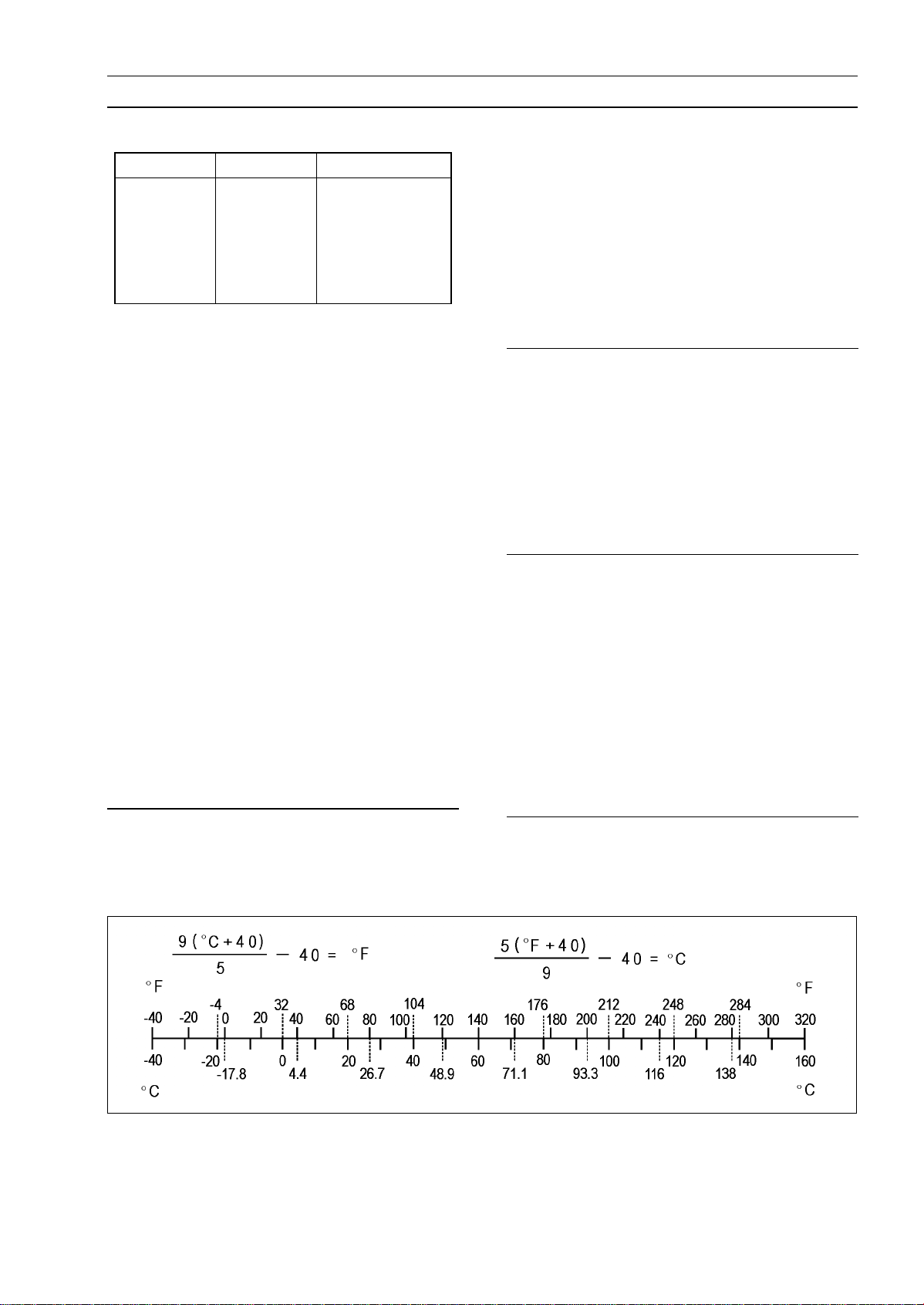
Units of Temperature:
Units of Power:
kW × 1.360 =
kW × 1.341 = HP
PS × 0.7355 = kW
PS × 0.9863 = HP
PS


PERIODIC MAINTENANCE 2-1
Periodic Maintenance
Table of Contents
Periodic Maintenance Chart................................................................................................... 2-3
Torque and Locking Agent...................................................................................................... 2-6
Specifications ......................................................................................................................... 2-12
Special Tools.......................................................................................................................... 2-14
Periodic Maintenance Procedures.......................................................................................... 2-15
Fuel System (DFI)................................................................................................................ 2-15
Air Cleaner Element Cleaning........................................................................................... 2-15
Throttle Control System Inspection................................................................................... 2-15
Engine Vacuum Synchronization Inspection..................................................................... 2-16
Idle Speed Inspection ....................................................................................................... 2-19
Idle Speed Adjustment...................................................................................................... 2-20
Fuel Hose Inspection (fuel leak, damage, installation condition)...................................... 2-20
Evaporative Emission Control System (CAL Model) ........................................................... 2-21
Evaporative Emission Control System Inspection ............................................................ 2-21
Cooling System.................................................................................................................... 2-22
Coolant Level Inspection................................................................................................... 2-22
Radiator Hose and Pipe Inspection (coolant leak, damage, installation condition) .......... 2-23
Engine Top End................................................................................................................... 2-23
Valve Clearance Inspection .............................................................................................. 2-23
Valve Clearance Adjustment............................................................................................. 2-24
Exhaust Butterfly Valve Cable Inspection......................................................................... 2-28
Exhaust Butterfly Valve Cable Adjustment........................................................................ 2-29
Air Suction System .............................................................................................................. 2-32
Air Suction System Damage Inspection............................................................................ 2-32
Clutch................................................................................................................................... 2-32
Clutch Operation Inspection.............................................................................................. 2-32
Wheels/Tires........................................................................................................................ 2-33
Air Pressure Inspection..................................................................................................... 2-33
Wheel/Tire Damage Inspection......................................................................................... 2-34
Tire Tread Wear Inspection............................................................................................... 2-34
Wheel Bearing Damage Inspection .................................................................................. 2-35
Drive Train ........................................................................................................................... 2-35
Drive Chain Lubrication Condition Inspection................................................................... 2-35
Drive Chain Slack Inspection............................................................................................ 2-36
Drive Chain Slack Adjustment .......................................................................................... 2-36
Wheel Alignment Inspection ............................................................................................. 2-37
Drive Chain Wear Inspection............................................................................................ 2-38
Chain Guide Wear Inspection........................................................................................... 2-38
Brake System ...................................................................................................................... 2-39
Brake Fluid Leak (Brake Hose and Pipe) Inspection ........................................................ 2-39
Brake Hose and Pipe Damage and Installation Condition Inspection............................... 2-40
Brake Operation Inspection .............................................................................................. 2-40
Brake Fluid Level Inspection ............................................................................................. 2-40
Brake Pad Wear Inspection.............................................................................................. 2-41
Brake Light Switch Operation Inspection.......................................................................... 2-42
Suspensions........................................................................................................................ 2-42
Front Forks/Rear Shock Absorber Operation Inspection.................................................. 2-42
Front Fork Oil Leak Inspection.......................................................................................... 2-43
Rear Shock Absorber Oil Leak Inspection........................................................................ 2-43
Rocker Arm Operation Inspection..................................................................................... 2-43
2

2-2 PERIODIC MAINTENANCE
Tie-Rod Operation Inspection........................................................................................... 2-43
Steering System ..................................................................................................................2-44
Steering P lay Inspection................................................................................................... 2-44
Steering P lay Adjustment.................................................................................................. 2-44
Steering S tem Bearing Lubrication................................................................................... 2-45
Electrical System................................................................................................................. 2-46
Spark Plug Condition Inspection....................................................................................... 2-46
Lights and Switches Operation Inspection........................................................................ 2-47
Headlight Aiming Inspection ............................................................................................. 2-49
Sidestand Switch Operation Inspection............................................................................ 2-50
Engine Stop Switch Operation Inspection......................................................................... 2-51
Others.................................................................................................................................. 2-52
Chassis Parts Lubrication................................................................................................. 2-52
Bolts, Nuts and Fasteners Tightness Inspection............................................................... 2-54
Replacement P arts .............................................................................................................. 2-55
Air Cleaner Element Replacement.................................................................................... 2-55
Fuel Hose Replacement ................................................................................................... 2-56
Coolant Change................................................................................................................ 2-58
Radiator Hose and O-ring Replacement........................................................................... 2-60
Engine Oil Change............................................................................................................ 2-60
Oil Filter Replacement ...................................................................................................... 2-61
Brake Hose and Pipe Replacement.................................................................................. 2-62
Brake Fluid Change.......................................................................................................... 2-64
Master Cylinder Rubber Parts Replacement .................................................................... 2-65
Caliper Rubber Parts Replacement.................................................................................. 2-66
Spark Plug Replacement.................................................................................................. 2-69
PERIODIC MAINTENANCE 2-3
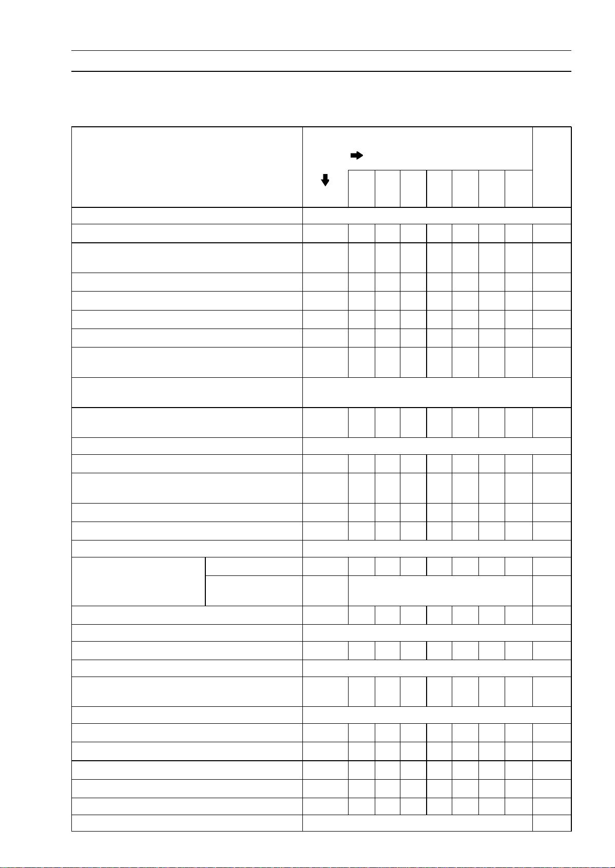
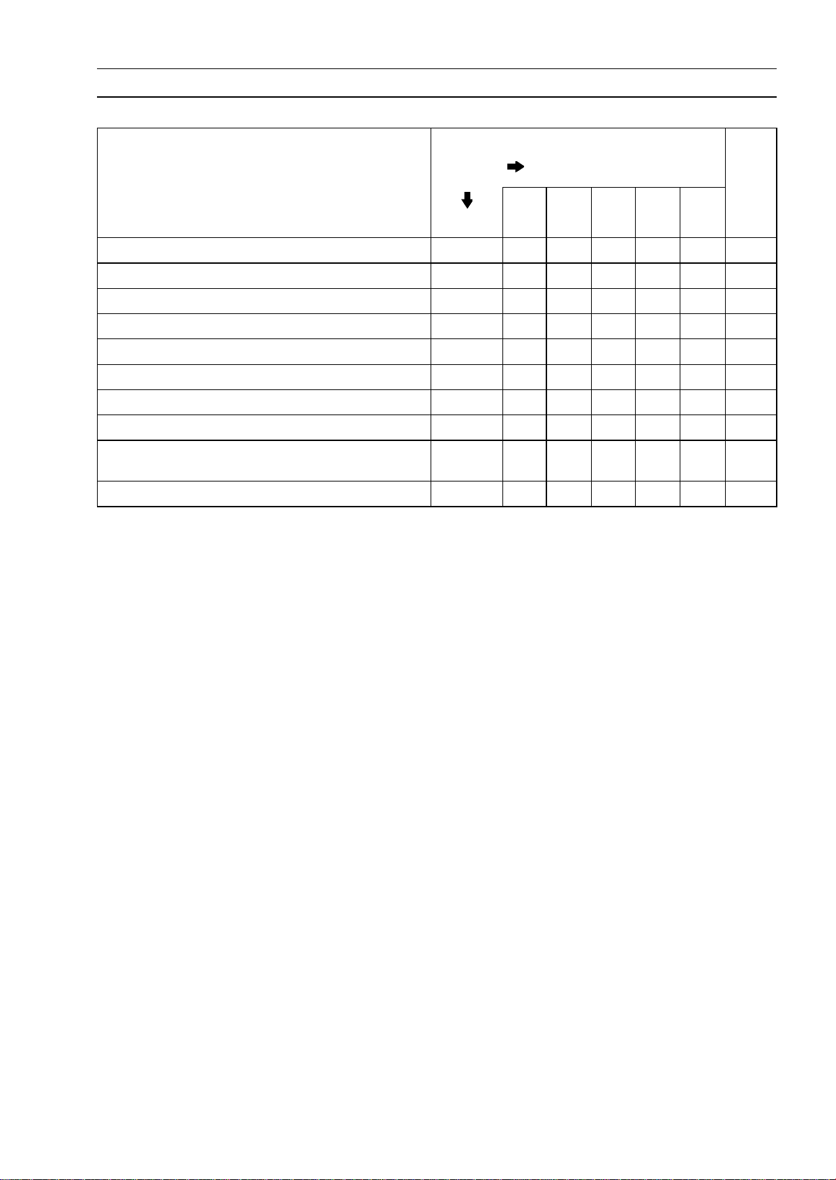
Periodic Maintenance Chart
The scheduled maintenance must be done in accordance with this chart to keep the motorcycle in
good running condition.The initial m aintenance is vitally important and must not be neglected.
Periodic Inspection
FREQUENCY Whichever
comes
first
1 6 12 18 24 30 36
INSPECTION Every (0.6) (4) (7.5) (12) (15) (20) (24)
Fuel System
* ODOMETER READING
× 1 000 km
(× 1 000 mile)
See
Page
Air cleaner element - clean
Throttle control system (play, smooth return,
no drag) - inspect
Engine vacuum synchronization - inspect
Idle speed - inspect
Fuel leak (fuel hose and pipe) - inspect year
Fuel hose and pipe damage - inspect year
Fuel hose and pipe installation condition -
inspect
Evaporative Emission Control System
(CAL)
Evaporative emission control system function
- inspect
Cooling System
Coolant level - inspect
Coolant leak (radiator hose and pipe) -
inspect
Radiator hose damage - inspect year
Radiator hose installation condition - inspect year
Engine Top End
year
year
year
• •
• • • •
• • •
• • • •
• • • •
• • • •
• • • •
• • • • • • •
• • • •
• • • •
• • • •
• • • •
2-15
2-15
2-16
2-19
2-20
2-20
2-20
2-21
2-22
2-23
2-23
2-23
US,CA, AU Model
Valve clearance - inspect
Exhaust butterfly valve cable - inspect
Air Suction System
Air suction system damage - inspect
Clutch
Clutch operation (play, disengagement,
engagement) - inspect
Wheels and Tires
Tire air pressure - inspect year
Wheel/tire damage - inspect
Tire tread wear, abnormal wear - inspect
Wheel bearing damage - inspect year
Drive Train
Drive chain lubrication condition - inspect # Every 600 km (400 mile) 2-35
Other than US,
CA, AU Model
Every 42 000 km (26 000 mile) 2-23
• • • • • • •
• • •
• • • •
• • •
• • •
• • •
• • •
•
2-23
2-28
2-32
2-32
2-33
2-34
2-34
2-35
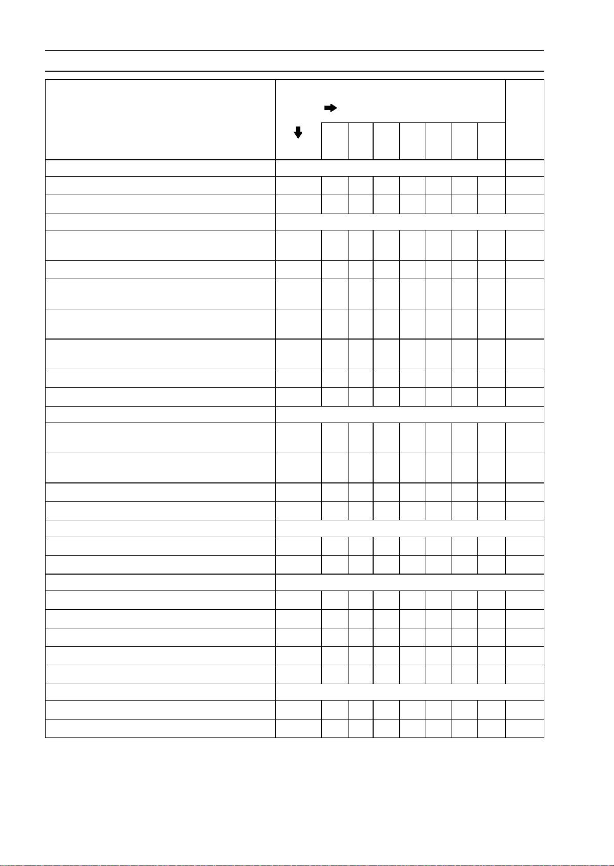
2-4 PERIODIC MAINTENANCE
Periodic Maintenance Chart
FREQUENCY Whichever
comes
first
1 6 12 18 24 30 36
INSPECTION Every (0.6) (4) (7.5) (12) (15) (20) (24)
Drive chain slack - inspect # Every 1 000 km (600 mile)
Drive chain wear - inspect #
Drive chain guide wear - inspect
Brake System
Brake fluid leak (brake hose and pipe) inspect
Brake hose and pipe damage - inspect year
Brake hose and pipe installation condition -
inspect
Brake operation (effectiveness, play, no
drag) - inspect
Brake fluid level - inspect
Brake pad wear - inspect #
Brake light switch operation - inspect
Suspensions
Front forks/rear shock absorber operation
(damping and smooth stroke) - inspect
Front forks/rear shock absorber oil leak inspect
year
year
year
6
months
year
• • • • • • •
• • • • • • •
• • • • • • •
• • • • • • •
• • • • • • •
• • • • • • •
* ODOMETER READING
× 1 000 km
(× 1 000 mile)
• • •
• • •
• • • • • •
• • •
• • •
See
Page
2-36
2-38
2-38
2-39
2-40
2-40
2-40
2-40
2-41
2-42
2-42
2-43
Rocker arm operation - inspect
Tie-rods operation - inspect
Steering System
Steering play - inspect year
Steering stem bearings - lubricate 2 years
Electrical System
Spark plug condition - inspect
Lights and switches operation - inspect year
Headlight aiming - inspect year
Sidestand switch operation - inspect year
Engine stop switch operation - inspect year
Others
Chassis parts - lubricate year
Bolts and nuts tightness - inspect
#: Service more frequently when operating in severe conditions; dusty,wet, muddy,high speed or
frequent starting/stopping.
*: For higher odometer readings, repeat at the frequency interval established here.
• • • •
• • • •
• • •
• • •
•
• • •
• • •
• • •
• • •
• • •
• • •
2-43
2-43
2-44
2-45
2-46
2-47
2-49
2-50
2-51
2-52
2-54
PERIODIC MAINTENANCE 2-5
Periodic Maintenance Chart
Periodic Replacement Parts
FREQUENCY Whichever
comes
first
CHANGE/REPLACE ITEM Every (0.6) (7.5) (15) (24) (30)
*ODOMETER READING
× 1 000 km
(× 1 000 mile)
1 12 24 36 48
See
Page
Air cleaner element #
Fuel hose 4 years
Coolant
Radiator hose and O-ring 3 years
Engine oil #
Oil filter year
Brake hose and pipe 4 years
Brake fluid 2 years
Rubber parts of master cylinder and caliper 4 years
Spark plug
#: Service more frequently when operating in severe conditions; dusty, wet, muddy, high speed or
frequent starting/stopping.
*: For higher odometer readings, repeat at the frequency interval established here.
3 years
year
• • • • •
• • • • •
• •
• • • •
•
•
•
•
•
•
2-55
2-56
2-58
2-60
2-60
2-61
2-62
2-64
2-65,
2-66
2-69
2-6 PERIODIC MAINTENANCE
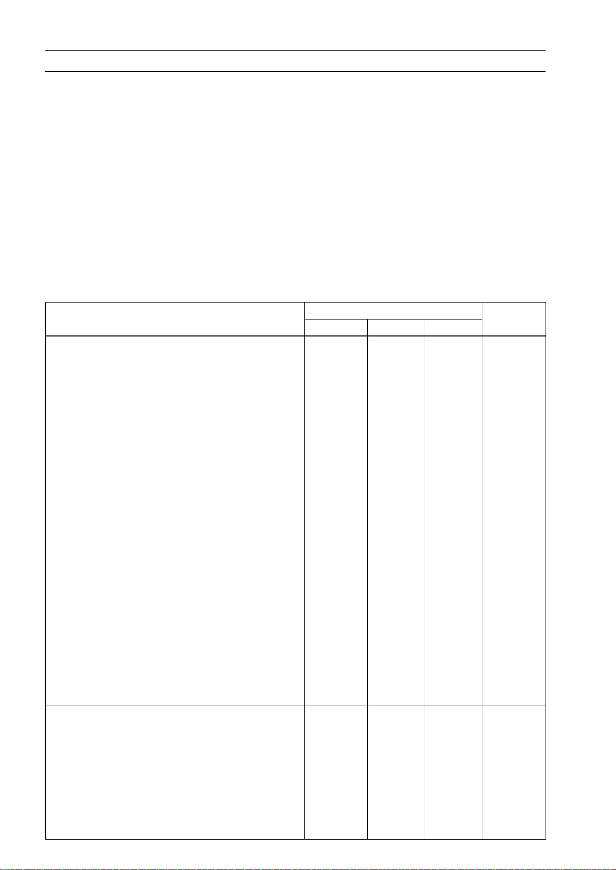
Torque and Locking Agent
The following tables list the tightening torque for the major fasteners requiring use of a
non-permanent locking agent or silicone sealant etc.
Letters used in the “Remarks” column mean:
AL: Tighten the two clamp bolts alternately two times to ensure even tightening torque.
EO: Apply engine oil.
G: Apply grease.
HG: Apply high-temperature grease.
L: Apply a non-permanent locking agent.
MO: Apply molybdenum disulfide grease oil solution.
(mixture of the engine oil and molybdenum disulfide grease in a weight ratio 10 : 1)
R: Replacement Parts
S: Follow the specified tightening sequence.
Si: Apply silicone grease (ex. PBC grease).
SS: Apply silicone sealant.
Fastener
Fuel System (DFI)
Air Cleaner Duct Screws 3.8 0.39 34 in·lb
Air Cleaner Housing Mounting Bolts 9.8 1.0 87 in·lb
Air Cleaner Housing Tapping Screws 1.2 0.12 11 in·lb
Air Duct Clamp Bolts 2.0 0.20 18 in·lb
Bypass Screw 0.2 0.02 1.8 in·lb
Camshaft Position Sensor Bolt 12 1.2 106 in·lb
Crankshaft Sensor Bolts 5.8 0.59 51 in·lb
Delivery Pipe Assy Mounting Screws 3.4 0.35 30 in·lb
Exhaust Butterfly Valve Actuator Bracket Bolt
Exhaust Butterfly Valve Actuator Mounting Bolts
Exhaust Butterfly Valve Actuator Pulley Bolt
Fuel Pump Bolts 9.8 1.0 87 in·lb L, S
Idle Adjusting Cable Clamp Screw 3.4 0.35 30 in·lb
Oxygen Sensor (Equipped Models) 44.1 4.50 32.5
Speed Sensor Bolt 12 1.2 106 in·lb
Throttle Body Assy Holder Bolts 13 1.3 115 in·lb
Throttle Body Assy Holder Clamp Bolts
Throttle Link Holder Screws 2.0 0.20 18 in·lb
Throttle Cable Plate Bolt 5.9 0.60 52 in·lb
Vehicle-down Sensor Bolts 6.0 0.61 53 in·lb
Water Temperature Sensor 25 2.5 18
Cooling System
Coolant Drain Bolt (Cylinder) 9.8 1.0 87 in·lb
Coolant Drain Bolt (Water Pump) 11 1.1 97 in·lb
Radiator Bracket Mounting Bolt 6.9 0.70 61 in·lb
Radiator Lower Bolt 6.9 0.70 61 in·lb
Radiator Upper Bolts 6.9 0.70 61 in·lb
Radiator (Water) Hose Clamp Screws 3.0 0.31 27 in·lb
Reserve Tank Bolts 9.8 1.0 87 in·lb
N·m
6.9 0.70 61 in·lb
6.9 0.70 61 in·lb
5.0 0.51 44 in·lb
2.0 0.20 18 in·lb
Torque
Remarks
kgf·m ft·lb
Loading...