

Page 1
B 80 W Bp
Register and win!
www.kaercher.com
59643610 03/13
Page 2

2
Page 3
Page 4
Page 5

http://www.kaercher.com/dealersearch
Page 6

Please read and comply with
these original instructions prior
to the initial operation of your appliance and
store them for later use or subsequent owners.
Contents
Safety instructions . . . . . . . EN . . 1
Function . . . . . . . . . . . . . . . EN . . 1
Proper use . . . . . . . . . . . . . EN . . 1
Environmental protection . . EN . . 1
Warranty . . . . . . . . . . . . . . . EN . . 1
Operating and Functional Ele-
ments . . . . . . . . . . . . . . . . . EN . . 2
Before Startup. . . . . . . . . . . EN . . 3
Operation . . . . . . . . . . . . . . EN . . 4
Shutting Down the Appliance EN . . 5
Grey Intelligent Key . . . . . . EN . . 5
Transport. . . . . . . . . . . . . . . EN . . 6
Storage . . . . . . . . . . . . . . . . EN . . 6
Maintenance and care . . . . EN . . 6
Frost protection. . . . . . . . . . EN . . 8
Faults . . . . . . . . . . . . . . . . . EN . . 9
Accessories . . . . . . . . . . . . EN . 10
Technical specifications . . . EN . 11
EC Declaration of Conformity EN . 11
Spare parts . . . . . . . . . . . . . EN . 11
Safety instructions
Before using the appliance for the first time,
read and observe these operating instructions and the accompanying brochure:
Safety information for brush cleaning units
and spray-extraction units, No. 5.956-251.
The appliance must only be operated on
surfaces that do not exceed the max. permitted incline (see "Technical Specifications").
The appliance may only be operated
when the hood and all lids are closed.
Remove the Intelligent Key (emergency
stop) to take all functions out of operation immediately.
Safety Devices
Safety devices serve to protect the user
and must not be rendered in operational or
their functions bypassed.
Driving lever
If the drive lever is released, the travel drive
and the brush drive shuts off.
Symbols in the operating
instructions
Danger
Immediate danger that can cause severe
injury or even death.
몇 Warning
Possible hazardous situation that could
lead to severe injury or even death.
Caution
Possible hazardous situation that could
lead to mild injury to persons or damage to
property.
Function
The scrubber vacuum is used for wet
cleaning or polishing of level floors.
– You can adjust the machine to suit the
cleaning task by modifying the settings
for water quantity, contact pressure of
the brushes, detergent quantity and
driving speed.
– The appliance is equipped with a fresh
water and a wastewater reservoir (80 litres each). These allow an effective
cleaning with a long usage life.
– Depending on the selected cleaning
head, the working width of the B 80 is
between 650 mm and 750 mm.
– This appliance is equipped with a travel
drive, drive motor and brush drive that
are driven by four batteries.
– The charger is already installed. Batter-
ies can be selected according to the
configuration (see Chapter "Recommended batteries“)
Note
The appliance can be equipped with various accessories depending on the cleaning
task.
Please request our catalogue or visit us on
the Internet at:
www.kaercher.com
Proper use
Use this appliance only as directed in these
operating instructions.
– The appliance may only be used for the
cleaning of hard surfaces that are not
sensitive to moisture and polishing operations.
– The appliance is not suited for the
cleaning of frozen grounds (e.g. in cold
stores).
– The appliance may only be equipped
with original accessories and spare
parts.
– The appliance is not suited for the use
in potentially explosive environments.
– The machine should not be used to
suck in inflammable gases, undiluted
acids or solvents.
This includes petrol, thinning agents or
hot oil that can form an explosive mixture when it comes in contact with
sucked air. Do not use acetone, undiluted acids and solvents as they are aggressive towards the materials from
which the appliance is made.
– The machine has been approved for
use on surfaces with max. gradients as
listed under "Technical Specifications".
Environmental protection
The packaging materials are recyclable. Please do not throw
packaging in the domestic
waste but pass it on for recycling.
Old units contain valuable recyclable materials. Batteries, oil
and similar substances may not
be released into the environment. Therefore please dispose
of old units through suitable collection systems.
Notes about the ingredients (REACH)
You will find current information about the
ingredients at:
www.kaercher.com/REACH
Warranty
The warranty terms published by our competent sales company are applicable in
each country. We will repair potential failures of your accessory within the warranty
period free of charge, provided that such
failure is caused by faulty material or defects in fabrication. In the event of a warranty claim please contact your dealer or the
nearest authorized Customer Service center. Please submit the proof of purchase.
6 EN
- 1
Page 7

Operating and Functional Elements
1 Parking brake
2 Rotary handle to incline the vacuum bar
3 Height adjustment of suction bar
4 Wing nuts for fastening the vacuum bar
5 Suction hose
6 Vacuum bar *
7 Connecting cable for charger
8 Storage compartment for mains cable
9 Driving lever
10 Operator console
11 Storage surface for cleaning set "Home
base box“
12 Cover dirt water reservoir
13 Holding rail for home base
14 Recessed grip
15 Cleaning head (illustration is symbolic) *
Brush rollers (BR model) Disk brushes
(BD model) *
16 Waste container (only BR)
17 Battery pole fuse
18 Battery *
19 Automatic fill of fresh water reservoir
(option)
20 Fresh water level display
21 Fresh water tank
22 Lock of the fresh water reservoir with fil-
ter
23 Homebase - accessories holder *
24 Coarse dirt sieve
25 Drain hose for wastewater with dosing
unit
Illustration of scrubbing vacuum
26 Push handle
27 Lock of wastewater reservoir
28 Flexible lock of rinsing system (option)
29 Wastewater reservoir rinsing system
(option)
30 Float
31 Fluff filter
32 Dirt water reservoir
33 Suction hose for detergent (only DOSE
model)
34 Detergent bottle (only DOSE model)
35 Fresh water reservoir filler neck
* not included in the delivery
Colour coding
– The operating elements for the cleaning
process are yellow.
– The controls for the maintenance and
service are light gray.
Operator console
3
1
1 Rotating button for drive speed
2 Intelligent Key
yellow - operator
grey - supervisor
3 Display
4 Program selection switch
5 Info button
6 Water quantity regulator
2
4
5
6
- 2
7EN
Page 8

Program selection switch
4
3
2
1
1 OFF
Device is switched off
2 Transport mode
Driving to the Place of Use.
3 Eco mode
Wet clean the floor (with reduced brush
speed) and vacuum up wastewater
(with reduced suction).
4 Normal mode
Wet clean the floor and vacuum up dirt
water.
5 Increased brush contact pressure
Wet clean the floor (with increased
brush contact pressure) and vacuum up
dirt water.
6 Intense mode
Wet clean the floor and allow the detergent to react.
7 Vacuum mode
Suck in the dirt fleet.
8 Polishing mode
Polishing the floor without the application of liquid.
5
6
8
Before Startup
Installing the Brushes
BD model
The disc brush must be installed before the
initial operation (see "Maintenance work").
BR model
The brushes are mounted.
Install batteries
Install the batteries (see "Care and Maintenance/Install and connect batteries").
7
Setting the charging marker line
Prior to the initial startup, following a service reset or when switching to another battery type, you must adjust the charging
marker line.
Use the Grey Intelligent Key.
Setting the charging marker line (see
Chapter "Grey Intelligent Key/Setting
the charging marker line“.
Using batteries made by other manufacturers
We recommend using our batteries as described in chapter "Care and Maintenance/
Recommended batteries".
Note
While using other batteries (for e.g. batteries from other manufacturers) the total discharge protection level must be reset by
the Kärcher after sales service according to
the respective battery.
Charging battery
Note
The appliance is equipped with a safety
mechanism to prevent total discharge, i.e.
when the permissible minimum capacity is
reached, the brush motor and the turbine
are switched off.
Drive the machine directly to the charg-
ing station; avoid any steep gradients in
the process.
Danger
Risk of injury on account of electric shock.
The mains voltage must correspond with
the type plate on the appliance.
Use the charger only in dry rooms with sufficient ventilation!
Charging process
Average charging time is approx. 10 -15
hours.
The built-in charger has electronic controls
and is suitable for all recommended batteries; it automatically switches off the charging process.
The built-in battery is shown on the display
during the charging process. If this is not
the case, the charging marker line must be
selected (see "Setting the charging marker
line").
The appliance must not be used during the
charging process.
Initial charge tips
With the initial charge, the control will not
yet be able to detect which battery type has
been installed. Keep charging the batteries
until the display shows a full charge (batteries may still not be completely charged).
The next charging process will have an accurate display and charge power and the
batteries will be fully charged.
Use the appliance until the deep discharge
protection switches off the brush motor and
the turbine after the initial charge of the battery. This procedure is necessary to adjust
the battery indicator. Only then the correct
battery status is displayed.
Insert the plug of the connecting cable
into the socket. The charging process
will start.
Note: The selected battery will be dis-
played during charging.
Charge until the display shows a full
charge.
Low maintenance batteries (wet batteries)
몇 Warning
Danger of causticization!
– Adding water to the battery in its dis-
charged state can cause the acid to
leak.
– Use safety glasses while handling bat-
tery acid and follow the safety instruc-
tions to avoid personal injury or damage
to clothes.
– Should the acid spray on to the skin or
clothes, rinse immediately with lots of
water.
Caution
Risk of damage!
– Use only distilled or desalinated water
(EN 50272-T3) for filling the battery.
– Do not add any substances (so-called
performance improving agents), else
warranty claims will not be entertained.
– Replace batteries only with batteries of
the same type. Otherwise, the charging
guideline must be readjusted by cus-
tomer service.
8 EN
- 3
Page 9

Installing the Vacuum Bar
Insert the vacuum bar into the vacuum
bar suspension in such a manner that
the profiled sheet is positioned above
the suspension.
Tighten the wing nuts.
Insert the suction hose.
Check if the height adjustment is
mounted on the inside of the vacuum
bar.
When the height adjustment is mounted
on the outside, the vacuum bar gets
caught at the bottom of the appliance.
Unloading
Danger
Risk of injury. Pull the Intelligent Key to take
all functions out of operation immediately.
Insert batteries and connect (see "Be-
fore Start-up").
Place long lateral boards of the packag-
ing as a ramp next to the pallet.
Fix the ramp on the pallet with nails.
Place short boards as a support under-
neath the ramp.
Remove the wooden bars in front of the
wheels.
Plug in the Intelligent Key.
Turn the program selection switch to
transport mode.
Press the driving lever and slowly move
the machine down from the ramp.
Remove the Intelligent Key.
Operation
Danger
In dangerous situations, release the drive
lever.
Parking brake
Loosen the parking brake; for that press
the pedal downward and move it to the
left. Then let the pedal go upward.
Activate immobilising brake. Press the
pedal downwards and move it to the
right to lock it.
Driving
Note
The machine is designed in such a way that
the brush head protrudes on the right. This
helps in working in a proper way even close
to the edges.
Plug in the Intelligent Key.
Preselect the speed on the drive speed
rotary knob.
Turn the programme selection switch to
transport mode.
Release parking brake.
Drive the machine.
Forwards:
Press the driving lever to the front.
Backward:
Press the driving lever to the rear.
Note
The machine moves only when the driving
lever is moved by 15°.
Stop the machine: Release driving lever.
Filling in detergents
Fresh water
Open the lock of the fresh water reser-
voir.
Fill fresh water (maximum 60 °C) until
the lower edge of the filling nozzle.
Close the lock of the fresh water reservoir.
With automatic fill of fresh water reservoir (option)
Connect the hose to the automatic fill-
ing system and open the water supply
(max. 60 °C, max. 5 bars).
Monitor the appliance - the automatic
filling system will interrupt the water
supply when the tank is full.
Shut off the water supply and discon-
nect the hose from the appliance.
Detergent
몇 Warning
Risk of damage. Only use the recommended detergents. With respect to different detergents the operator bears the increased
risk regarding the operational safety and
danger of accident.
Only use detergents that are free from solvents, hydrochloric acid and hydrofluoric
acid.
Follow the safety instructions for using detergents.
Note
Do not use highly foaming detergents.
Recommended detergents:
Application Detergent
Routine cleaning of all water resistant floors
Routine cleaning of glossy
surfaces (e.g. granite)
Routine cleaning and basic
cleaning of industrial floors
Routine cleaning and basic
cleaning of fine stoneware
tiles
Routine cleaning of tiles in
sanitary areas
Cleaning and disinfection in
sanitary areas
Removal of coating from all
alkali-resistant floors (e.g.
PVC)
Removal of coating from linoleum floors
Appliance with dosing equipment DOSE
(option)
Detergent is added to the fresh water on
the way to the cleaning head with the help
of a dosaging device.
Note
The metering device can be used to add
3% of detergent at maximum. In case of a
higher dose the detergent must be poured
into the fresh water tank.
Place the detergent bottle into the hold-
er.
Close the bottle lid.
Insert the suction hose of the dosaging
equipment into the bottle.
Note
If the fresh water tank is empty, then the
function of adding detergent gets deactivated. The cleaning head continues to work
without the addition of any liquid. Detergent
addition is also stopped when the detergent
can is empty.
Models without dosing equipment
Add the detergent to the fresh water
reservoir.
RM 746
RM 780
RM 755 es
RM 69 ASF
RM 753
RM 751
RM 732
RM 752
RM 754
Setting the water quantity
Adjust the water quantity using the reg-
ulating button according to the dirt on
the floor covering.
Note
Carry out the initial cleaning attempts with
little quantities of water. Increase water
quantity step-by-step until the desired
cleaning result is achieved.
The detergent pump of the dosing equipment does not start working until a minimum water volume is present.
- 4
9EN
Page 10

Setting the Vacuum Bar
Oblique position
To improve the vacuuming result on tiled
floors the vacuum bar can be turned to an
oblique position of up to 5°.
Loosen the wing nuts.
Turn the vacuum bar.
Tighten the wing screws.
Inclination
If the vacuum result is unsatisfactory the inclination of the straight vacuum bar can be
modified.
Adjust the rotary handle to incline the
suction bar.
Setting the parameters
With yellow Intelligent Key
Parameters for the different cleaning programmes are preset in the appliance.
Depending on the authorisation of the yellow Intelligent Key, individual parameters
can be changed.
The modification of the parameters is only
valid until another cleaning programme is
selected via the programme selection
switch.
If you wish to permanently change the parameters, you must use a grey Intelligent
Key. This adjustment procedure is described in the section "Grey Intelligent
Key“.
Note:
Almost all displayed text regarding parameter adjustment is self-explanatory. The
only exception is the parameter FACT:
– Fine Clean: Lower brush speed for re-
moving the grey film on fine stone
floors.
– Whisper Clean: Medium brush speed
for regular cleaning with reduced noise
level.
– Power Clean: High brush speed for pol-
ishing, crystallising and sweeping.
Turn the program selection switch to
the desired cleaning program.
Turn the info button until the desired pa-
rameter is displayed.
Press Info button - the set value blinks.
Set the desired value by turning the info
button.
Confirm the changed setting by press-
ing the Info button or wait till the set value is automatically accepted after 10
seconds.
Cleaning
Caution
Risk of damage to the floor covering. Do
not operate the appliance on the spot.
Turn the program selection switch to
the desired cleaning program.
Lower the cleaning head
The appliance controls the lowering
and raising of the cleaning head automatically, depending on the selected
programme mode. The brush motor
also runs and stops automatically.
Note
The brush motor comes to a halt when the
machine stops and when there is overload.
Lower the vacuum bar
The appliance controls the lowering
and raising of the suction bar automatically, depending on the selected programme mode.
Note
For cleaning tiled floors, set the straight
vacuum bar in such a way that cleaning is
done at right angles to the joints.
The inclined position and the inclination of
the vacuum bar can be adjusted to achieve
better suction results (see "Setting the Vacuum Bar").
If the wastewater reservoir is full, the
floater will close the suction opening and
the suction turbine will run at a higher
speed. If this is the case, shut the vacuum
off and drive to empty the wastewater reservoir.
Shutting Down the Appliance
Close the regulatory button for setting
the water quantity.
Release driving lever.
Set the program selection switch to suc-
tion or vacuuming.
Briefly drive forward and suck of the re-
maining water.
Remove the Intelligent Key.
Charge battery, if required.
Drain off dirt water
몇 Warning
Please observe the local provisions regarding the wastewater treatment.
Take the water discharge hose from the
support and lower above a suited collection device.
Crush or bend the dosing equipment.
Open the lid of the dosing equipment.
Drain off the dirt water - regulate the
water quantity by pressing or bending.
Rinse the wastewater reservoir with
clean water or with the rinsing system
for the wastewater reservoir (option).
Drain off clean water
Loosen the lid for emptying the fresh
water - do not remove it fully. Drain wa-
ter.
To rinse the fresh water reservoir, re-
move the cover completely and remove
the fresh water filter.
Grey Intelligent Key
Plug in the Intelligent Key.
Select the desired function by turning
the Info button.
The different functions are described in the
following.
Key menu >>
In this menu item, the authorisations for the
yellow Intelligent Keys are released.
Press the info button while "Key menu
>>“ is displayed.
Remove the grey Intelligent Key and in-
sert the yellow Intelligent Key to be pro-
grammed.
Select the desired menu item to be
modified by turning the Info button.
Press Info button.
Adjust the menu item by turning the Info
button.
Confirm the setting by pressing the
menu item.
Select the next menu item to be modi-
fied by turning the Info button.
To save the authorisations, retrieve the
menu "Save settings" by turning the info
button and pressing it.
To exit, retrieve the menu "Exit menu"
by turning the info button and pressing
it.
Cleaning App >>
Parameters that are adjusted with the grey
Intelligent Key, are kept until another setting is selected.
Turn the program selection switch to
the desired cleaning program.
Turn the info button until "Cleaning App
>>“ is displayed.
Press the info button - the first adjusta-
ble parameter is displayed.
Press Info button - the set value blinks.
Set the desired value by turning the info
button.
10 EN
- 5
Page 11

Confirm the changed setting by press-
ing the Info button or wait till the set value is automatically accepted after 10
seconds.
Select the next parameter by turning
the Info button.
After all desired parameters have been
modified, turn the info button until "Exit
menu" is displayed.
Press the info button - you will exit the
menu.
Setting the language
Press Info button - the set value blinks.
Set the desired language by turning the
info button.
Confirm the changed setting by press-
ing the Info button or wait till the set value is automatically accepted after 10
seconds.
Brush trailing
Adjust the trailing time of the brushes.
Same adjustment as "Set language".
Setting the charging marker line
Turn the info button until the function
"Battery menu" is displayed.
Press the info button - select the charg-
ing marker line according to the built-in
batteries.
Note: Setting the charging marker line
should be discussed with Kärcher customer service. This applies especially if
the battery is not listed in the menu.
Confirm the changed setting by press-
ing the Info button or wait till the set value is automatically accepted after 10
seconds.
LOAD DEFAULT
Recreate the basic settings.
Transport
Danger
Risk of injury! When loading or unloading
the machine, it may only be operated on
gradients of max. incline (see "Technical
Specifications"). Drive slowly.
Caution
Risk of injury and damage! Observe the
weight of the appliance when you transport
it.
Remove the brush to avoid damage to
the brushes.
When transporting in vehicles, secure
the appliance according to the guidelines from slipping and tipping over.
Storage
Caution
Risk of injury and damage! Note the weight
of the appliance in case of storage.
This appliance must only be stored in interior rooms.
Maintenance and care
Danger
Risk of injury! Before working on the appliance, remove the Intelligent Key and the
mains plug of the charger.
Drain and dispose of the dirt water and
the residual fresh water.
Maintenance schedule
Maintenance intervals
Perform the maintenance task shown
on the display.
Vacuum bar
Clean the filter
Water filter
Clean the filter
Suction lips
opinion
Turbine
Clean filter
Brush
Clean or replace
Press the Info Button, the display will be
reset. The display will be shown again
at certain predefined time intervals.
After each operation
Caution
Risk of damage. Do not wash down the appliance with water and do not use aggressive detergents.
Drain off dirt water.
Rinse the wastewater reservoir with
clean water or with the rinsing system
for the wastewater reservoir (option).
Remove the coarse dirt sieve from the
wastewater reservoir and clean it.
Clean the outside of the appliance with
a damp cloth which has been soaked in
mild detergent.
Check the fluff filter, clean if required.
Only BR model: Remove bulk waste
container and empty it.
Only BR model: Clean water distributor
channel (see section „Maintenance
work“).
Clean the vacuum lips and the wiping
lips, check for wear and replace if required.
Check the brushes for wear, replace if
required.
Press the lock of the wastewater reser-
voir in and close the cover of the wastewater reservoir so that a gap remains
open to facilitate drying.
Monthly
Check battery poles for oxidation, brush
off if necessary. Ensure that the con-
nection cable sits firmly.
Clean the seals between dirt water res-
ervoir and cover and check for tight-
ness, replace if required.
Check the acid density of the cells if the
batteries are not maintenance-free bat-
teries.
Clean the brush tunnel (only BR model).
Yearly
Have the prescribed inspection carried
out by the customer service.
Maintenance Works
Wastewater reservoir rinsing system
(option)
Take the dirt water discharge hose from
the support and lower above a suited
collection device.
Open the lid of the dosing equipment.
Open the cover of the wastewater res-
ervoir.
Pull the flexible lock off of the rinsing
system.
Connect the water hose to the rinsing
system.
Close the cover of the wastewater res-
ervoir until it rests on the flexible lock.
Open the water supply and rinse the
wastewater reservoir for about 30 sec-
onds.
Repeat the rinsing process 2 to 3 times.
Shut off the water supply and discon-
nect the hose from the appliance.
- 6
11EN
Page 12

Replace or turn vacuum lips
1 Wear indicator
2 Vacuum lip
The vacuum lips must be replaced or reversed if they are worn down to the wear indicator.
Remove the vacuum bar.
Unscrew the star grips.
Insert a new brush roller.
Reassemble the bearing lid in the re-
verse sequence.
Repeat process on the opposite side.
Replacing the disk brushes
Press the pedal for changing the brush-
es downward beyond its resistance.
1 Spring element
2 Push handle
Insert the push bow into the cleaning
head intake.
Push the spring elements down and
lock them into place.
1 Excenter lever
2 Locking pin
Remove the plastic parts.
Remove the vacuum lips.
Insert new or reversed vacuum lips.
Insert the plastic parts.
Screw in and tighten the star grips.
Clean water distribution channel
Remove the rubber strip and clean the
channel with a cloth. After cleaning, replace the rubber strip evenly.
Replacing the brush rollers
Loosen the lock of the wiper flap.
Push the bearing lid down and remove.
Pull out the brush rollers.
Note: The brush rollers must be replaced when the bristle length has
reached 10 mm.
Pull the disc brush out of the side below
the cleaning head.
Hold the new disc brush under the
cleaning head, push upward and lock.
Install cleaning head
Push the appliance forward about 2 m
so that the steering rollers point toward
the rear.
1 Spring element
2 Locking pin
3 Terminal strip cover
4 Lock of safety pin
5 Excenter lever
Remove the terminal strip cover.
Place the cleaning head halfway in front
of the appliance.
Connect the mains supply cable of the
cleaning head to the appliance.
Attach the terminal strip cover.
Connect the hose couplers on the
cleaning head to the hose on the appliance.
Open the excenter lever of the slideable
intake on the lift arm.
Lower the lift arm of the appliance
(use only the grey Intelligent Key); pro-
ceed as follows:
Rotate the info button to the menu
"Manual control" and then press it.
Rotate the info button and select the
menu "Brush head".
Press the info button - lift arm will lower,
press info button again to stop it.
Press the cleaning head all the way
against the push handle.
Note: The less play the cleaning head
has after being installed, the less vibra-
tion will occur during cleaning.
Move the intake and insert the safety
pin and lock it into place.
Close the excenter lever.
Select the installed cleaning head (R
or D)
in the menu (use only the grey In-
telligence Key).
Dismantling the cleaning head
The removal will take place in the opposite
order of the installation.
Caution
When the cleaning head is removed, the
stability of the appliance can be compromised; ensure a safe stance.
Possibly support the rear to prevent tipping.
12 EN
- 7
Page 13

Batteries
Please observe the following warning notes
when handling batteries:
Observe the directions on the battery, in the instructions for use and
in the vehicle operating instructions
Wear eye protection
Keep children away from acid and
batteries
Danger of explosion
Fire, sparks, naked flames and
smoking must be strictly avoided
Danger of chemical burns
First aid
Warning note
Disposal
Insert batteries and connect
Caution
When the batteries are installed and removed, the stability of the appliance can be
compromised; ensure a safe stance.
Push the appliance forward about 2 m
so that the steering rollers point toward
the rear.
Hold the wastewater reservoir by the
handle recess and swivel the reservoir
upwards toward the side.
Insert all four batteries into the trough.
The 240 Ah batteries are seated flush in
the battery intake, no holding blocks are
required.
For the 170 Ah and 180 Ah batteries, 2
holding blocks must be installed in the
front and one in the right rear on the
floor. In addition to that, a foam strip is
inserted on the rear left.
몇 Warning
Pay attention to correct poles.
Removing the batteries
Caution
Risk of damage due to tipping appliance;
remove batteries only if the appliance is
equipped with a cleaning head.
Remove the Intelligent Key.
Push the appliance forward about 2 m
so that the steering rollers point toward
the rear.
Hold the wastewater reservoir by the
handle recess and swivel the reservoir
upwards toward the side.
Clamp off the minus pole of the battery.
Clamp off the remaining cables from the
battery.
Remove the support blocks.
Remove the batteries.
Caution
When the batteries are installed and removed, the stability of the appliance can be
compromised; ensure a safe stance.
Dispose of the used batteries according
to the local provisions.
Maintenance contract
To ensure a reliable operation of the appliance maintenance contracts can be concluded with the competent Kärcher sales
office.
Do not throw the battery into the
regular waste
Danger
Danger of explosion. Do not put tools or
similar on the battery, i.e. on the terminal
poles and cell connectors.
Risk of injury. Ensure that wounds never
come into contact with lead. Always clean
your hands after having worked with batteries.
Recommended batteries, B 80
Order No. Description
6.654-119.0
6.654-124.0
6.654-242.0
6.654-086.0
** Appliance requires 4 batteries
1)
Complete set (24 V/240 Ah) incl. connect-
ing cable, order no. 4.035-393.0
2)
Complete set (24 V/180 Ah) incl. connect-
ing cable, order no. 4.035-387.0
3)
Complete set (24 V/170 Ah) incl. connect-
ing cable, order no. 4.035-388.0
4)
Complete set (24 V/180 Ah) incl. connect-
ing cable, order no. 4.035-440.0
1)
240 Ah - maintenance-free
2)
180 Ah - maintenance-free
3)
170 Ah - maintenance-free
4)
180 Ah, - low maintenance
6 V**
6 V**
6 V**
6 V**
1 Connecting cable of battery (-)
2 Connecting cable of battery (+)
3 short connecting cable
4 long connecting cable
Connect the batteries as shown, use
the included connecting cables for this.
Connect the connection cable to the
free battery poles (+) and (-).
Note: The red connecting cable has an
increased protective layer. In order for
the tank not to touch when close, the
connecting cable must be connected as
shown in the illustration.
Tilt the wastewater tank down.
몇 Warning
Charge the battery before commissioning
the machine.
Frost protection
In case of danger of frost:
Empty the fresh and dirt water reser-
voirs.
Store the appliance in a frost-protected
room.
- 8
13EN
Page 14

Faults
Danger
Risk of injury! Before working on the appliance, remove the Intelligent Key and the
mains plug of the charger.
Drain and dispose of the dirt water and
the residual fresh water.
Faults with display
Display Remedy
ERR_I_BÜRSTE_049 Check if foreign matters block the brushes; remove foreign matter if required.
ERR_I_TURB_050 Check suction turbine for contamination and clean it if necessary.
ERR_U_BATT_001 Check battery; charge it if required.
If the display shows different error messages or if the error cannot be remediated:
Remove the Intelligent Key.
Wait for 10 seconds.
Plug in the Intelligent Key.
If the fault recurs, call customer service.
Faults without display on the console
Fault Remedy
Machine does not move Stand-by. Turn the appliance off and reinsert the Intelligent Key.
Turn the program selection switch to the desired programme.
Release parking brake.
Check battery; charge it if required.
Make sure that all battery terminals are connected.
Insufficient water
quantity
Do not add detergents Increase the water volume to activate the dosing pump.
Insufficient vacuum
performance
Insufficient cleaning
result
Vibrations during
cleaning
Brushes do not turn Check if foreign matters block the brushes; remove foreign matter if required.
In case of faults that cannot be remedied using the table below please contact the customer service.
Check fresh water level, refill tank if necessary.
Increase the water volume on the regulating knob for water volume.
Unscrew the lock of the fresh water reservoir. Remove and clean the fresh water filter. Insert the filter and screw
in the lock.
Remove the water distribution strip from the cleaning head and clean water canal (only R cleaning head).
Check hoses for blockages; clean if required.
Check the detergent level
Clean the seals between dirt water reservoir and cover and check for tightness, replace if required.
Wastewater reservoir is full; shut off the appliance and empty the wastewater reservoir
Clean the fluff filter.
Clean the vacuum lips on the vacuum bar, replace if required
Check suction hose for blockages; clean if required.
Check the suction hose for tightness; replace if required.
Check if the cover on the dirt water discharge hose is closed
Check the setting of the vacuum bar.
Check the brushes for wear, replace if required.
Cleaning head has play, open the excenter lever and press the cleaning head all the way against the push handle, close the excenter lever.
You might need to use softer brushes.
If over-current switch in the electronics system has been triggered, turn programme selection switch to "OFF".
Afterwards, set it back to the desired programme.
14 EN
- 9
Page 15

Accessories
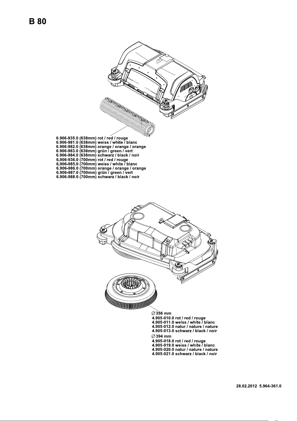
BR appliance B 80 (brush roller accessories)
Description Part no.:
Working
width 650
mm
Brush roller, red (medium, standard) 6.906-935.0 6.906-936.0 Also for regular cleaning of heavily dirtied
Brush roller, white (soft) 6.906-981.0 6.906-985.0 For polishing and cleaning sensitive floors. 1 2
Brush roller, orange (high/ low) 6.906-982.0 6.906-986.0 For scrubbing structured floors (safety tiles,
Brush roller, green (hard) 6.906-983.0 6.906-987.0 For thoroughly cleaning heavily dirtied floors
Brush roller, black (very hard) 6.906-984.0 6.906-988.0 1 2
Pad roller shaft 4.762-433.0 4.762-434.0 For intake of roller pads. 1 2
Roller pad, yellow (soft) 6.369-454.0 6.369-454.0 For polishing floors. 20 96; 106
Roller pad, red (medium) 6.369-456.0 6.369-456.0 For cleaning slightly dirtied floors. 20 96; 106
Roller pad, green (hard) 6.369-455.0 6.369-455.0 For cleaning normal to heavily dirtied floors. 20 96; 106
Part no.:
Working
width 750
mm
Description
floors.
etc.).
and for removing the coating (for e.g. of wax,
acrylate).
Packaging unit
Appliance requires
12
12
12
BD appliances B 80 (disc roller accessories)
Description Part no.:
Working
width 650
mm
Part no.:
Working
width 750
mm
Description
Disk brush, natural (white) 4.905-012.0 4.905-020.0 For polishing floors. 1 2
Disk brush, white 4.905-011.0 4.905-019.0 For polishing and cleaning sensitive floors. 1 2
Disk brush, red (medium, standard) 4.905-010.0 4.905-018.0 For cleaning slightly dirtied or sensitive floors. 1 2
Disk brush, black (hard) 4.905-013.0 4.905-021.0 For cleaning heavily dirtied floors. 1 2
Driver plate pad 4.762-446.0 4.762-447.0 For intake of pads. 1 2
Packaging unit
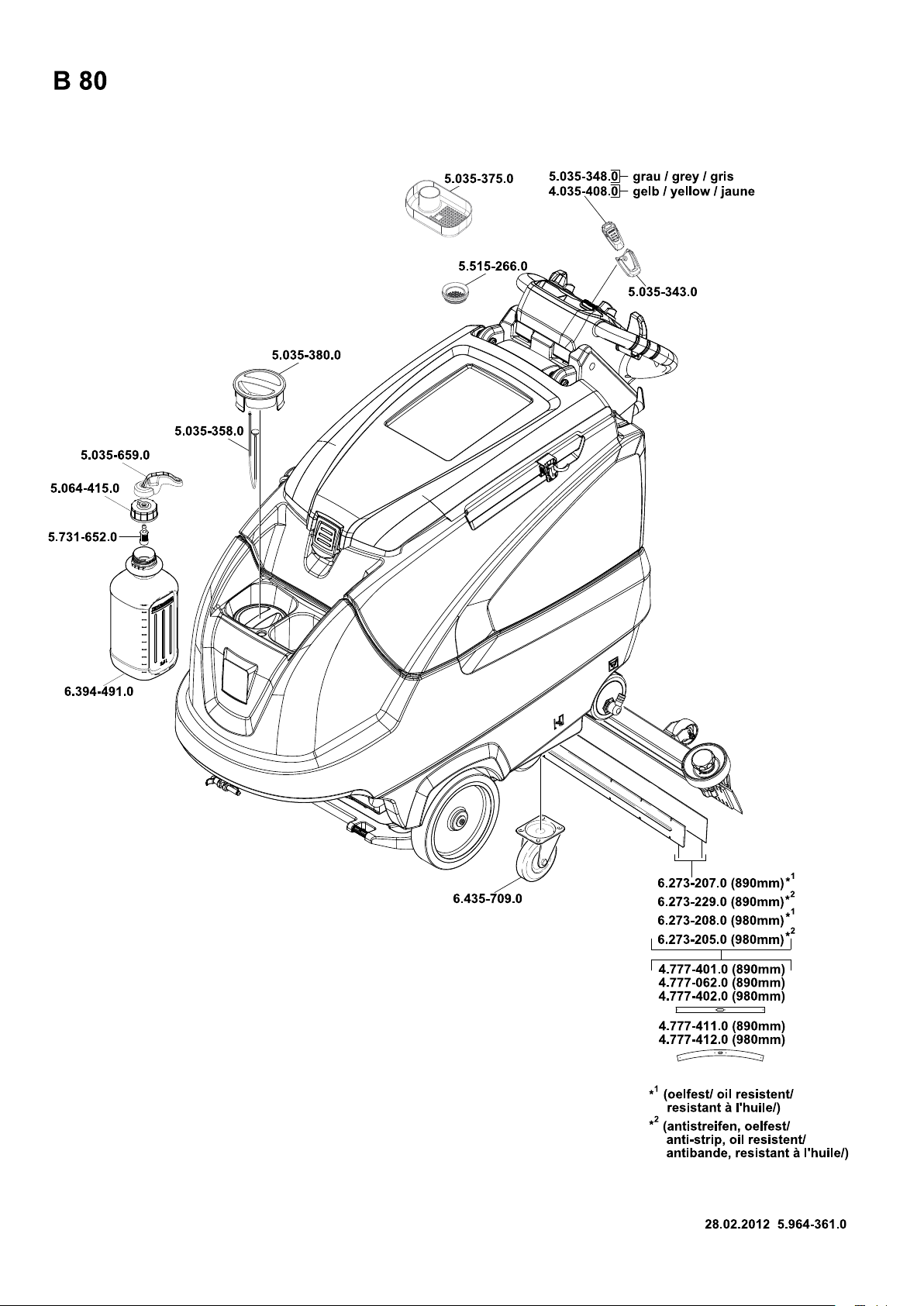
BR/BD appliances B 80 (vacuum bar accessories)
Description Part no.:
Working width
850 mm
Rubber lip, blue 6.273-214.0 6.273-213.0 Standard pair 1 pair
Rubber lip, transparent, grooved 6.273-207.0 6.273-208.0 oil-resistant pair 1 pair
Rubber lip, transparent 6.273-229.0 6.273-205.0 Non-scarring pair 1 pair
Rubber lip, transparent 6.273-290.0 6.273-291.0 For difficult floors pair 1 pair
Vacuum bar, straight 4.777-401.0 4.777-402.0 Standard 1 1
Vacuum bar, bent 4.777-411.0 4.777-412.0 Standard 1 1
Part no.:
Working width
940 mm
Description Pack-
aging
unit
Appliance requires
Appliance requires
- 10
15EN
Page 16

Technical specifications
BR appliance
B 80
BD appliance
B 80
R 65 R 75 D 65 D 75
Power
Nominal voltage V 24
Battery capacity Ah (5h) 170, 180, 240
Average power consumption W 2200
Drive motor output (rated output) W 350
Suction engine output W 580
Brush engine output W 2 x 600
Vacuuming
Vacuum power, air volume (max.) l/s 25
Vacuuming power, negative pressure (max.) mbar / kPa 167 / 16,7
Cleaning brushes
Brush speed 1/min 400 - 1550 180
Dimensions and weights
Theoretical surface cleaning performance m²/h 3900 4500 3900 4500
Max. working range incline % 2
Fresh/dirt water reservoir volume l 80/80
Max. water temperature °C 60
max. water pressure MPa (bar) 0,5 (5)
Net weight (transport weight) kg 280 (with 240 Ah batteries)
Total weight (ready to operate) kg 360 (with 240 Ah batteries)
Values determined as per EN 60335-2-72
Total oscillation value m/s
Uncertainty K m/s
Sound pressure level L
Uncertainty K
pA
Sound power level L
pA
+ Uncertainty K
WA
WA
2
2
0,1
0,1
dB(A) 69
dB(A) 2
dB(A) 83
Subject to technical modifications!
EC Declaration of Conformity
We hereby declare that the machine described below complies with the relevant
basic safety and health requirements of the
EU Directives, both in its basic design and
construction as well as in the version put
into circulation by us. This declaration shall
cease to be valid if the machine is modified
without our prior approval.
Product: Floor cleaner
Type: B 80 W Bp
Relevant EU Directives
2006/42/EC (+2009/127/EC)
2004/108/EC
Applied harmonized standards
EN 55014–1: 2006+A1: 2009+A2: 2011
EN 55014–2: 1997+A1: 2001+A2: 2008
EN 60335–1
EN 60335–2–29: 2004+A2: 2010
EN 60335–2–72
EN 61000–3–2: 2006+A1: 2009+A2: 2009
EN 61000–3–3: 2008
EN 62233: 2008
Applied national standards
-
CEO
Head of Approbation
Authorised Documentation Representative
S. Reiser
Alfred Kärcher GmbH Co. KG
Alfred-Kärcher-Str. 28 - 40
71364 Winnenden (Germany)
Phone: +49 7195 14-0
Fax: +49 7195 14-2212
Winnenden, 2011/05/01
Spare parts
– Only use accessories and spare parts
which have been approved by the manufacturer. The exclusive use of original
accessories and original spare parts
ensures that the appliance can be operated safely and trouble free.
– At the end of the operating instructions
you will find a selected list of spare
parts that are often required.
– For additional information about spare
parts, please go to the Service section
at www.kaercher.com.
The undersigned act on behalf and under
the power of attorney of the company management.
16 EN
- 11
 Loading...