


UXJ-50
22032200303
UX-J50
SERVICE MANUAL
MICRO COMPONENT SYSTEM
UX-J50
RM-SUXJ50R REMOTE CONTROL
SP-UXJ50
SP-UXJ50CA-UXJ50
Area Suffix
B -------------------------- U.K.
E ------- Continental Europe
EN --------- Northern Europe
TABLE OF CONTENTS
1 Important Safety Precautions . . . . . . . . . . . . . . . . . . . . . . . . . . . . . . . . . . . . . . . . . . . . . . . . . . . . . . . . . . . 1-2
2 Disassembly method . . . . . . . . . . . . . . . . . . . . . . . . . . . . . . . . . . . . . . . . . . . . . . . . . . . . . . . . . . . . . . . . . . 1-6
3 Adjustment. . . . . . . . . . . . . . . . . . . . . . . . . . . . . . . . . . . . . . . . . . . . . . . . . . . . . . . . . . . . . . . . . . . . . . . . . . 1-19
4 Description of major ICs. . . . . . . . . . . . . . . . . . . . . . . . . . . . . . . . . . . . . . . . . . . . . . . . . . . . . . . . . . . . . . . 1-25
COPYRIGHT © 2003 VICTOR COMPANY OF JAPAN, LTD.
No.22032
2003/03
UX-J50
Important Safety Precautions
1.1 Safety Precautions
(1) This design of this product contains special hardware and
many circuits and components specially for safety purposes.
For continued protection, no changes should be made to the
original design unless authorized in writing by the manufacturer. Replacement parts must be identical to those
used in the original circuits. Services should be performed by qualified personnel only.
(2) Alterations of the design or circuitry of the product should
not be made. Any design alterations of the product should
not be made. Any design alterations or additions will void
the manufacturers warranty and will further relieve the
manufacture of responsibility for personal injury or property
damage resulting therefrom.
(3) Many electrical and mechanical parts in the products have
special safety-related characteristics. These characteristics are often not evident from visual inspection nor can the
protection afforded by them necessarily be obtained by using replacement components rated for higher voltage, wattage, etc. Replacement parts which have these special safety
characteristics are identified in the Parts List of Service Manual. Electrical components having such features are identified by shading on the schematics and by ( ) on the
Parts List in the Service Manual. The use of a substitute replacement which does not have the same safety characteristics as the recommended replacement parts shown in the
Parts List of Service Manual may create shock, fire, or other hazards.
(4) The leads in the products are routed and dressed with ties,
clamps, tubings, barriers and the like to be separated from
live parts, high temperature parts, moving parts and/or
sharp edges for the prevention of electric shock and fire
hazard. When service is required, the original lead routing
and dress should be observed, and it should be confirmed
that they have been returned to normal, after reassembling.
(5) Leakage shock hazard testing)
After reassembling the product, always perform an isolation
check on the exposed metal parts of the product (antenna
terminals, knobs, metal cabinet, screw heads, headphone
jack, control shafts, etc.) to be sure the product is safe to
operate without danger of electrical shock.
Do not use a line isolation transformer during this check.
• Plug the AC line cord directly into the AC outlet. Using a
"Leakage Current Tester", measure the leakage current
from each exposed metal parts of the cabinet, particularly any exposed metal part having a return path to the
chassis, to a known good earth ground. Any leakage current must not exceed 0.5mA AC (r.m.s.).
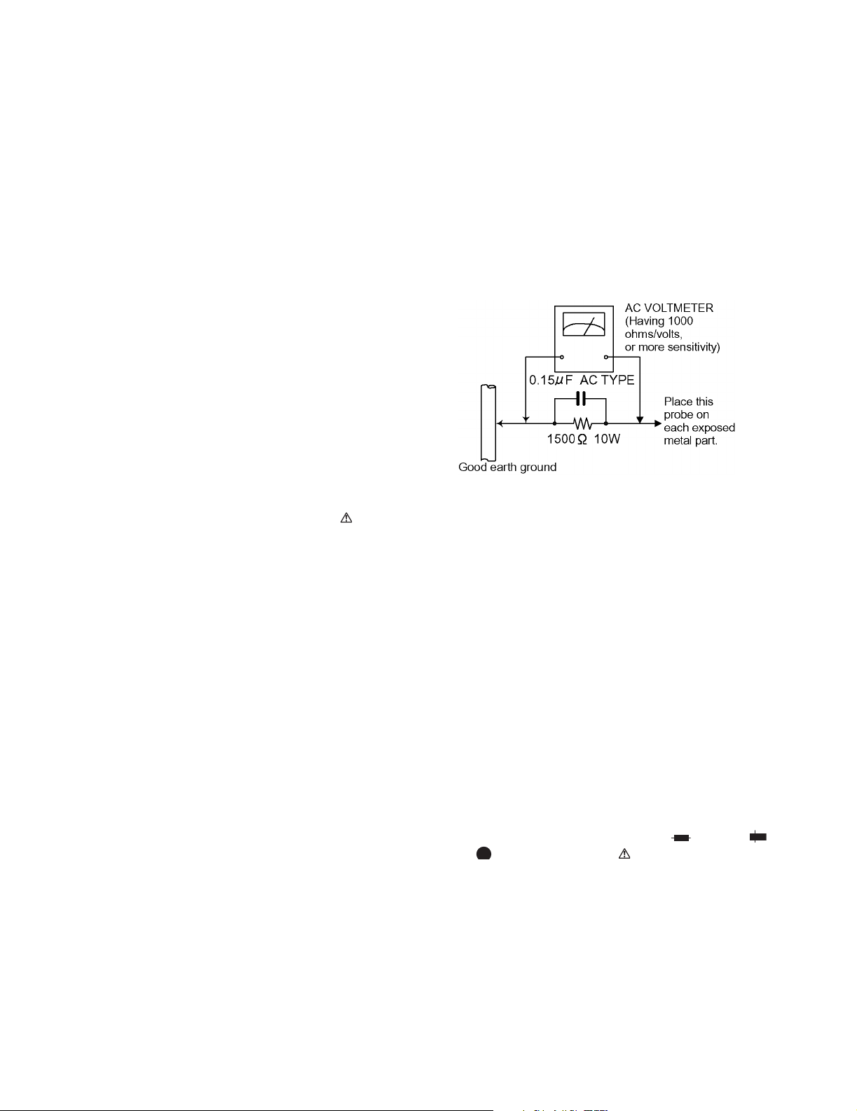
• Alternate check method
Plug the AC line cord directly into the AC outlet. Use an AC
voltmeter having, 1,000 ohms per volt or more sensitivity in
the following manner. Connect a 1,500 ohm 10W resistor
paralleled by a 0.15 µF AC-type capacitor between an
SECTION 1
exposed metal part and a known good earth ground.
Measure the AC voltage across the resistor with the AC
voltmeter.
Move the resistor connection to each exposed metal part,
particularly any exposed metal part having a return path to
the chassis, and measure the AC voltage across the resistor.
Now, reverse the plug in the AC outlet and repeat each
measurement. Voltage measured any must not exceed 0.75
V AC (r.m.s.). This corresponds to 0.5 mA AC (r.m.s.).
1.2 Warning
(1) This equipment has been designed and manufactured to
meet international safety standards.
(2) It is the legal responsibility of the repairer to ensure that
these safety standards are maintained.
(3) Repairs must be made in accordance with the relevant
safety standards.
(4) It is essential that safety critical components are replaced
by approved parts.
(5) If mains voltage selector is provided, check setting for local
voltage.
1.3 Caution
Burrs formed during molding may be left over on some parts
of the chassis.
Therefore, pay attention to such burrs in the case of preforming repair of this system.
1.4 Critical parts for safety
In regard with component parts appearing on the silk-screen
printed side (parts side) of the PWB diagrams, the parts that are
printed over with black such as the resistor ( ), diode ( )
and ICP ( ) or identified by the " " mark nearby are critical
for safety.
When replacing them, be sure to use the parts of the same type
and rating as specified by the manufacturer. (Except the JC version)
1-2 (No.22032)
1.5 Safety Precautions (U.K only)
(1) This design of this product contains special hardware and many circuits and components specially for safety purposes. For con-
tinued protection, no changes should be made to the original design unless authorized in writing by the manufacturer. Replacement parts must be identical to those used in the original circuits.
(2) Any unauthorised design alterations or additions will void the manufacturer's guarantee; furthermore the manufacturer cannot
accept responsibility for personal injury or property damage resulting therefrom.
(3) Essential safety critical components are identified by ( ) on the Parts List and by shading on the schematics, and must never
be replaced by parts other than those listed in the manual. Please note however that many electrical and mechanical parts in
the product have special safety related characteristics. These characteristics are often not evident from visual inspection. Parts
other than specified by the manufacturer may not have the same safety characteristics as the recommended replacement parts
shown in the Parts List of the Service Manual and may create shock, fire, or other hazards.
(4) The leads in the products are routed and dressed with ties, clamps, tubings, barriers and the like to be separated from live parts,
high temperature parts, moving parts and/or sharp edges for the prevention of electric shock and fire hazard. When service is
required, the original lead routing and dress should be observed, and it should be confirmed that they have been returned to
normal, after re-assembling.
1.5.1 Warning
(1) Service should be performed by qualified personnel only.
(2) This equipment has been designed and manufactured to meet international safety standards.
(3) It is the legal responsibility of the repairer to ensure that these safety standards are maintained.
(4) Repairs must be made in accordance with the relevant safety standards.
(5) It is essential that safety critical components are replaced by approved parts.
(6) If mains voltage selector is provided, check setting for local voltage.
UX-J50
Burrs formed during molding may be left over on some parts of the chassis. Therefore,
pay attention to such burrs in the case of preforming repair of this system.
(No.22032)1-3
UX-J50
1.6 Preventing static electricity
Electrostatic discharge (ESD), which occurs when static electricity stored in the body, fabric, etc. is discharged,
can destroy the laser diode in the traverse unit (optical pickup). Take care to prevent this when performing repairs.
1.6.1 Grounding to prevent damage by static electricity
Static electricity in the work area can destroy the optical pickup (laser diode) in devices such as CD players.
Be careful to use proper grounding in the area where repairs are being performed.
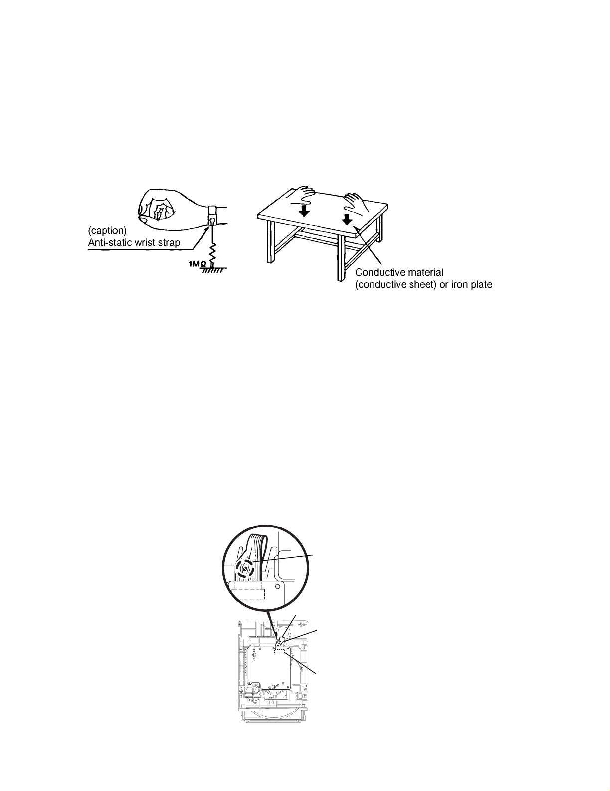
(1) Ground the workbench
Ground the workbench by laying conductive material (such as a conductive sheet) or an iron plate over it before placing the
traverse unit (optical pickup) on it.
(2) Ground yourself
Use an anti-static wrist strap to release any static electricity built up in your body.
(3) Handling the optical pickup
• In order to maintain quality during transport and before installation, both sides of the laser diode on the replacement optical
pickup are shorted. After replacement, return the shorted parts to their original condition.
(Refer to the text.)
• Do not use a tester to check the condition of the laser diode in the optical pickup. The tester's internal power source can easily
destroy the laser diode.
1.7 Handling the traverse unit (optical pickup)
(1) Do not subject the traverse unit (optical pickup) to strong shocks, as it is a sensitive, complex unit.
(2) Cut off the shorted part of the flexible cable using nippers, etc. after replacing the optical pickup. For specific details, refer to the replace-
ment procedure in the text. Remove the anti-static pin when replacing the traverse unit. Be careful not to take too long a time
when attaching it to the connector.
(3) Handle the flexible cable carefully as it may break when subjected to strong force.
(4) I t is not possible to adjust the semi-fixed resistor that adjusts the laser power. Do not turn it.
1.8 Attention when traverse unit is decomposed
*Please refer to "Disassembly method" in the text for the CD pickup unit.
• Apply solder to the short land sections before the flexible wire is disconnected from the connector CN101 on the CD servo board.
(If the flexible wire is disconnected without applying solder, the CD pickup may be destroyed by static electricity.)
• In the assembly, be sure to remove solder from the short land sections after connecting the flexible wire.
Shorting round
1-4 (No.22032)
Flexible wire
Shorting round
CN601 on
mechanism
board
1.9 Important for laser products
(1) CLASS 1 LASER PRODUCT
(2) DANGER : Invisible laser radiation when open and inter
lock failed or defeated. Avoid direct exposure to beam.
(3) CAUTION : There are no serviceable parts inside the
Laser Unit. Do not disassemble the Laser Unit. Replace the
complete Laser Unit if it malfunctions.
(4) CAUTION : The compact disc player uses invisible laser
radiation and is equipped with safety switches which
prevent emission of radiation when the drawer is open and
the safety interlocks have failed or are de feated.
It is dangerous to defeat the safety switches.
UX-J50
(5) CAUTION : If safety switches malfunction, the laser is able
to function.
(6) CAUTION : Use of controls, adjustments or performance of
procedures other than those specified herein may result in
hazardous radiation exposure.
CAUTION
Please use enough caution not to see the beam directly
or touch it in case of anadjustment or operation check.
VARNING
Osynlig laserstrålning är denna del är öppnad och spårren är
urkopplad. Betrakta ej strålen.
VARO
Avattaessa ja suojalukitus ohitettaessa olet alttiina näkymättömälle lasersäteilylle. Älä katso säteeseen.
REPRODUCTION AND POSITION OF LABELS
ADVARSEL
Usynlig laserstråling ved åbning, når sikkerhedsafbrydere er
ude af funktion. Undgå udsasttelse for stråling.
ADVARSEL
Usynlig laserstråling ved åpning, når sikkerhetsbryteren er avslott. unngå utsettelse for stråling.
Caution label
(No.22032)1-5
UX-J50
r
A
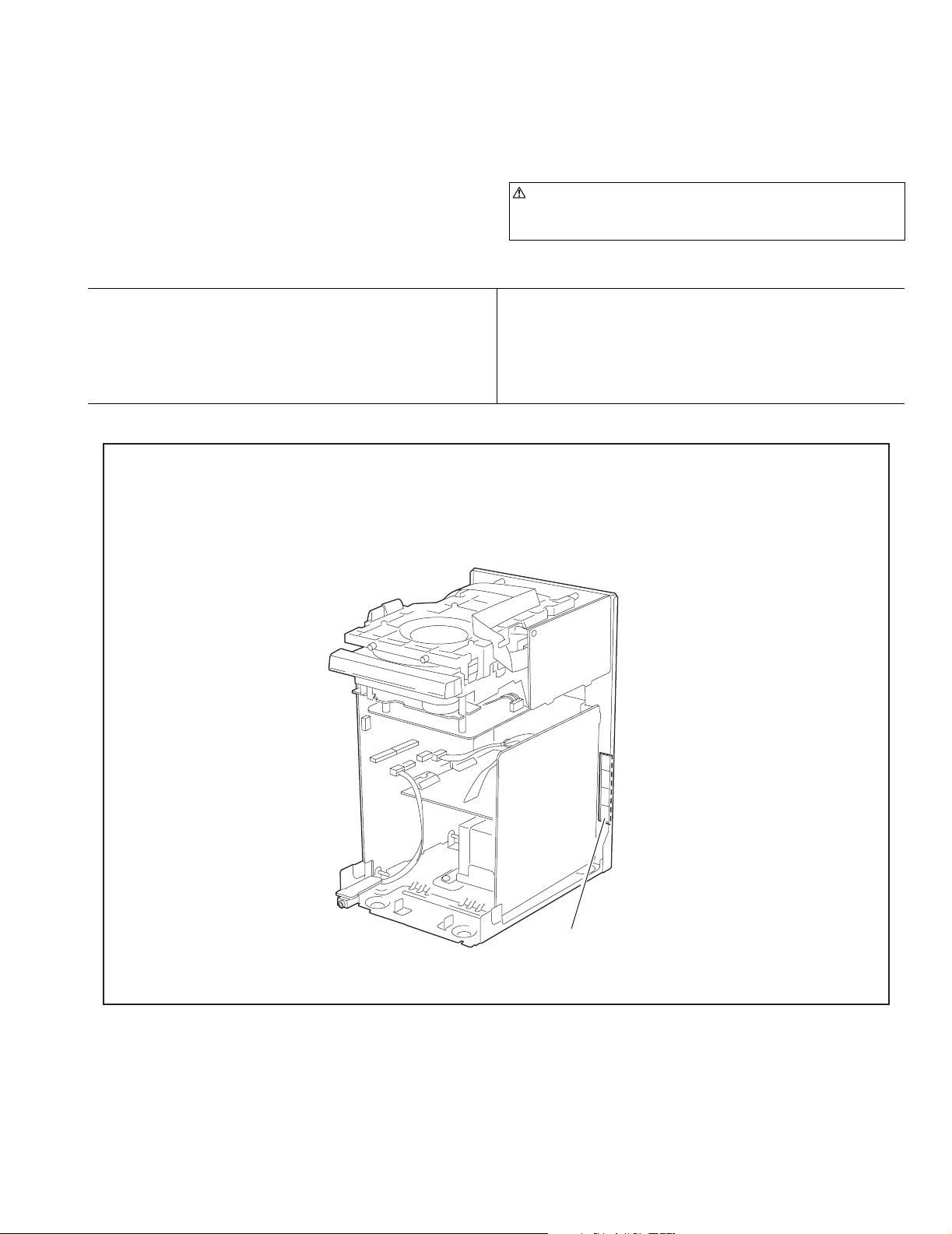
2.1 Main body
2.1.1 Removing the metal cover
(See Fig.1~3)
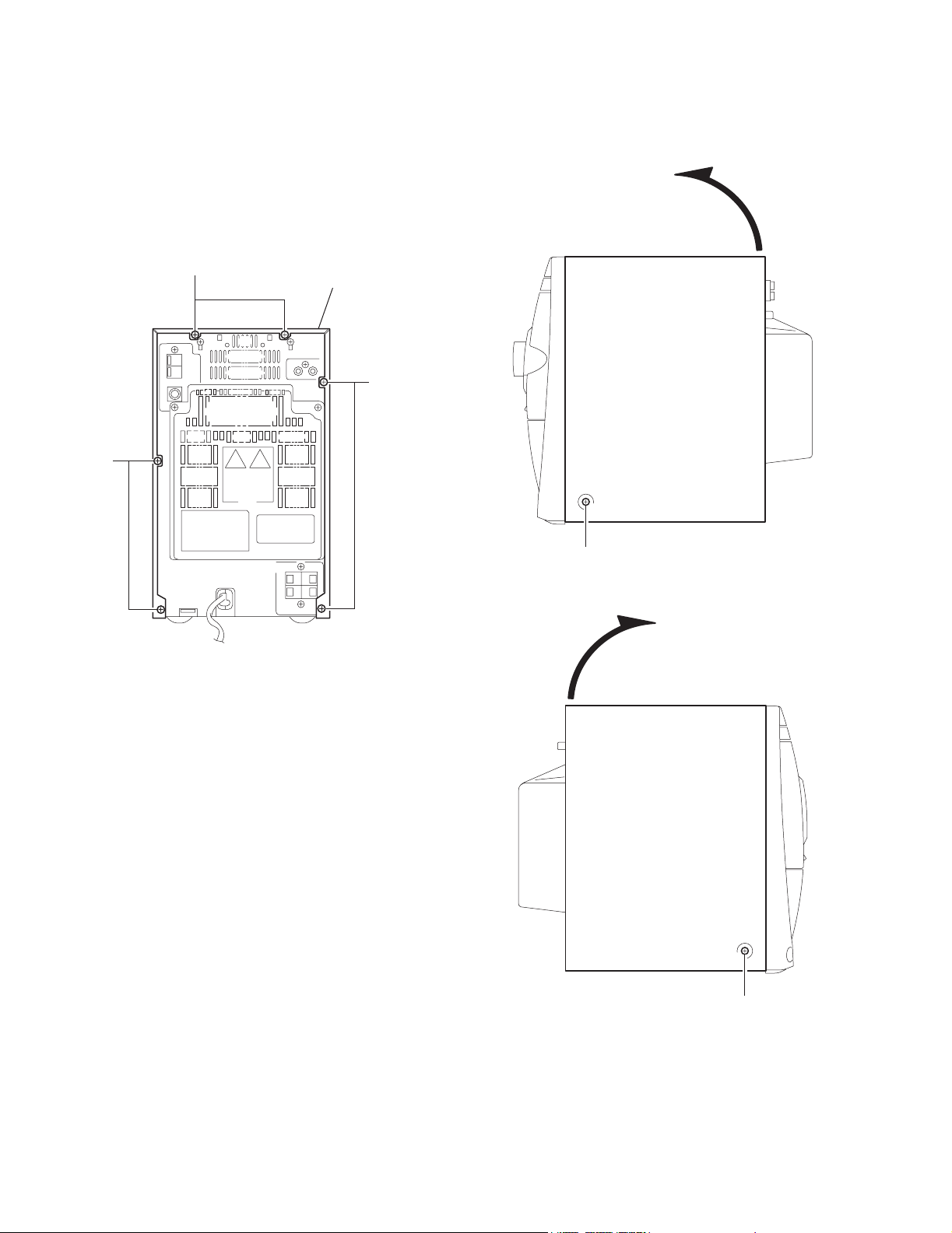
(1) Remove the six screws A on the back of the main body.
(2) Remove the two screws B on each side and remove the
metal cover in the direction of the arrow.
SECTION 2
Disassembly method
A
Metal cove
A
B
Fig.2
Fig.1
B
Fig.3
1-6 (No.22032)
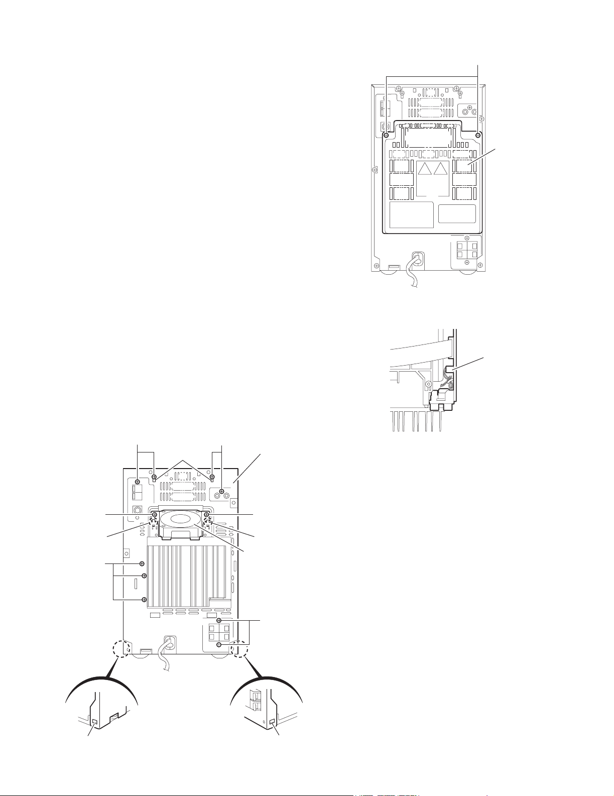
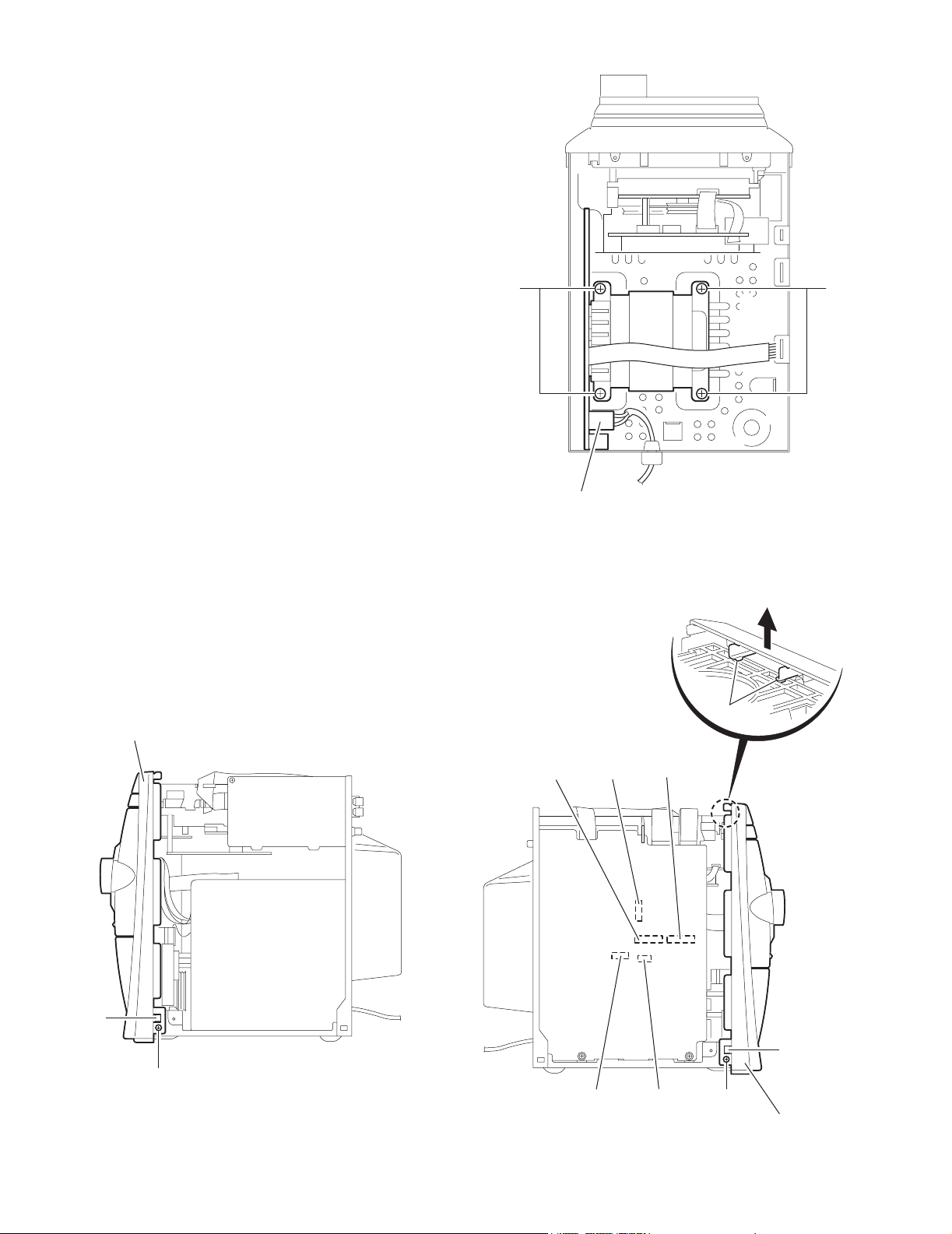
2.1.2 Removing the rear cover
r
(See Fig.4)
(1) Remove the two screws C attaching the rear cover.
2.1.3 Removing the rear panel / fan assembly
(See Fig.5,6)
• Prior to performing the following procedure, remove the metal
cover and the rear cover.
(1) Remove the nine screws D attaching the rear panel. Re-
lease the two joints a on the rear side and the two joints
b on each side.
(2) Remove the two screws E attaching the fan bracket and
release the two joints c on the rear panel, and remove.
(3) Disconnect the wire from the connector CN916 on the main
board.
UX-J50
C
Rear cove
Fig.4
Main board
CN916
D
DD
a
Rear panel
Fig.6
EE
cc
Fan assembly
D
b
Fig.5
b
(No.22032)1-7

UX-J50
2.1.4 Removing the tuner board
(See Fig.7)
• Prior to performing the following procedure, remove the metal
cover.
(1) Disconnect the card wire from the connector CN1 on the
tuner board.
(2) Remove the two screws F on the rear side and the screw
G in the side.
2.1.5 Removing the CD-R/RW mechanism assembly
(See Fig.8)
• Prior to performing the following procedure, remove the metal
cover, the rear cover, the rear panel and the tuner board.
(1) Disconnect the card wire from the connector CN903,
CN902 and CN904 on the main board.
(2) Pull the joint d in the direction of the arrow and remove the
CD-R/RW mechanism assembly backward while releasing
the joint e .
G
Tuner board
CN1
Fig.7
CD-R/RW mechanism assembly
F
d
d
Main board
e
CN903
CN904
CN902
Fig.8
1-8 (No.22032)
UX-J50
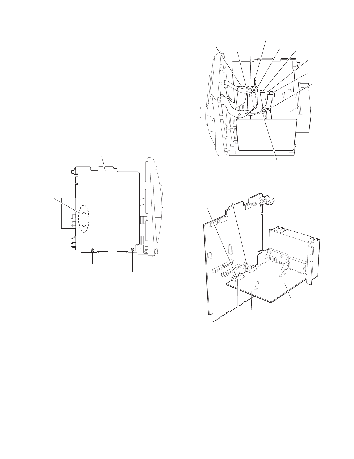
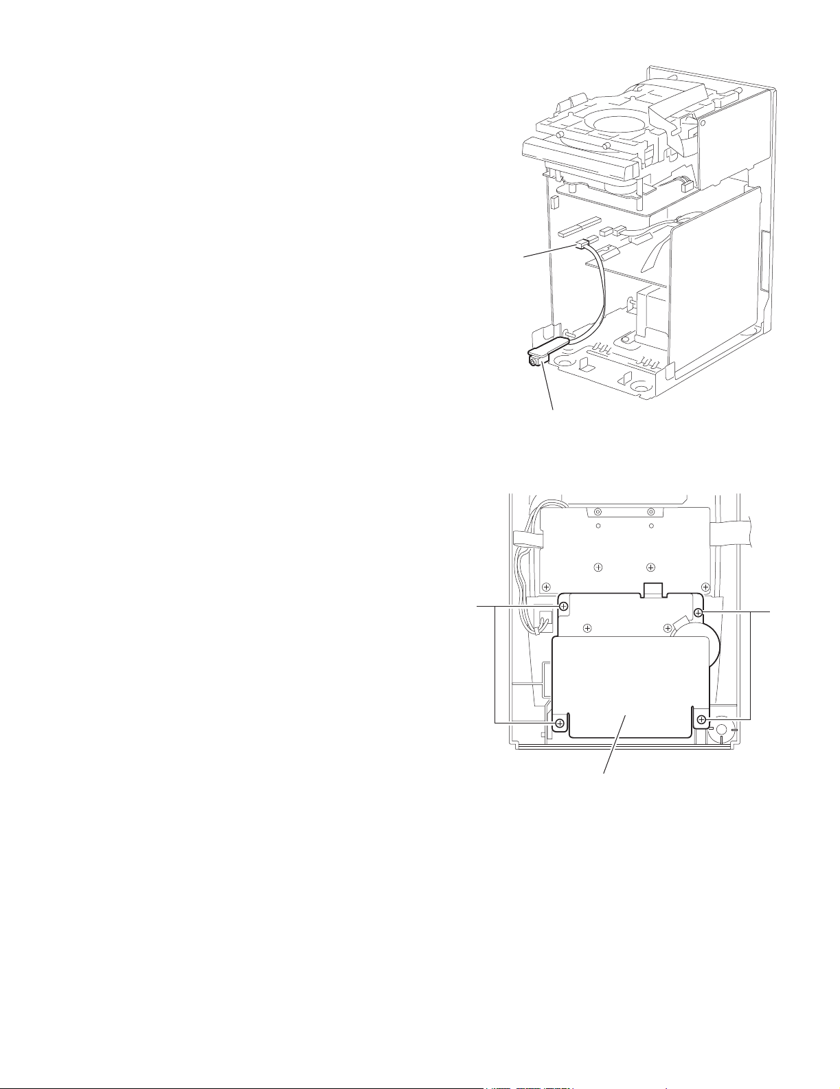
2.1.6 Removing the main board / the heat sink board / the
speaker jack board
(See Fig.9~11)
• Prior to performing the following procedure, remove the metal
cover, the rear cover, the rear panel, the tuner board and the
CD-R/RW mechanism assembly.
(1) Remove the two screws H attaching the main board.
(2) Disconnect the card wire from the connector
CN900,CN901,CN930,CN931 and CN932, and disconnect
the flat wire from the connector CN913,CN917 and CN918
on the main board.
(3) Remove the band and disconnect the flat wire from the
connector CN951 on the power transformer assembly, and
then remove the main board / the heat sink board from the
body.
(4) Release the two joints f of the main board and disconnect
the connector CN944 and CN945 of the heat sink board
from the connector CN912 and CN911 of the main board
respectively, and remove.
Main board
f
CN930
CN912
CN913
Main board
CN911
Main board
CN932
CN931
Power transformer assembly
Fig.10
CN901
CN951
CN900
CN917
CN918
Band
Fig.9
H
Heat sink board
CN945
CN944
Fig.11
(No.22032)1-9
UX-J50
2.1.7 Removing the power transformer assembly
(See Fig.12)
• Prior to performing the following procedure, remove the metal
cover, the rear cover, the rear panel, the CD-R/RW mechanism assembly and the main board.
(1) Disconnect the power cord from the connector J1000 on
the power transformer assembly.
(2) Remove the four screws J .
JJ
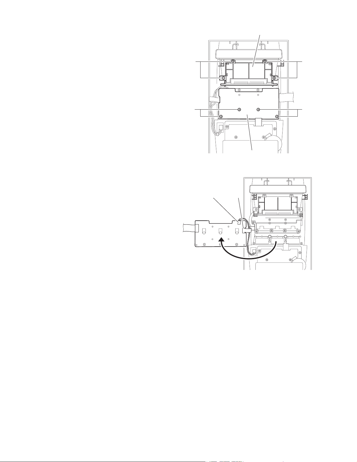
2.1.8 Removing the front panel assembly
(See Fig.13,14)
• Prior to performing the following procedure, remove the metal
cover.
(1) Remove the two screws K on each side. Release the two
joints g on the both sides and lift the front panel assembly
to release the joint h .
(2) Disconnect the card wire from the connector CN900,
CN901, CN930, CN931 and CN932 on the main board.
Front panel assembly
Power transformer assembly
J1000
Fig.12
h
Main board
CN932CN931 CN930
g
1-10 (No.22032)
K
Fig.13
CN900
CN901
Fig.14
g
K
Front panel assembly
2.1.9 Removing the phones board
(See Fig.15)
• Prior to performing procedure, remove the metal cover and the
front panel assembly.
(1) Disconnect the flat wire from the connector CN913 on the
main board.
UX-J50
Mian board
CN913
2.1.10 Removing the cassette mechanism assembly
(See Fig.16)
• Prior to performing the following procedure, remove the metal
cover and the front panel assembly.
(1) Remove the four screws L attaching the cassette mecha-
nism assembly.
Phones board
Fig.15
L
Cassette mechanism assembly
Fig.16
L
(No.22032)1-11
UX-J50
2.1.11 Removing the switch board
(See Fig.17,18)
• Prior to performing the following procedure, remove the metal
cover and the front panel assembly.
(1) Remove the four screws M attaching the switch board.
(2) Move the switch board in the direction of the arrow to dis-
connect the wire from the connector CN762 and the card
wire from the connector CN761.
2.1.12 Remove the LCD board assembly
(See Fig.17)
• Prior to performing the following procedure, remove the metal
cover and the front panel assembly.
(1) Remove the four screws N attaching the LCD board as-
sembly.
M
Switch board
CN762 CN761
LCD board assembly
NN
M
Switch board
Fig.17
Fig.18
1-12 (No.22032)
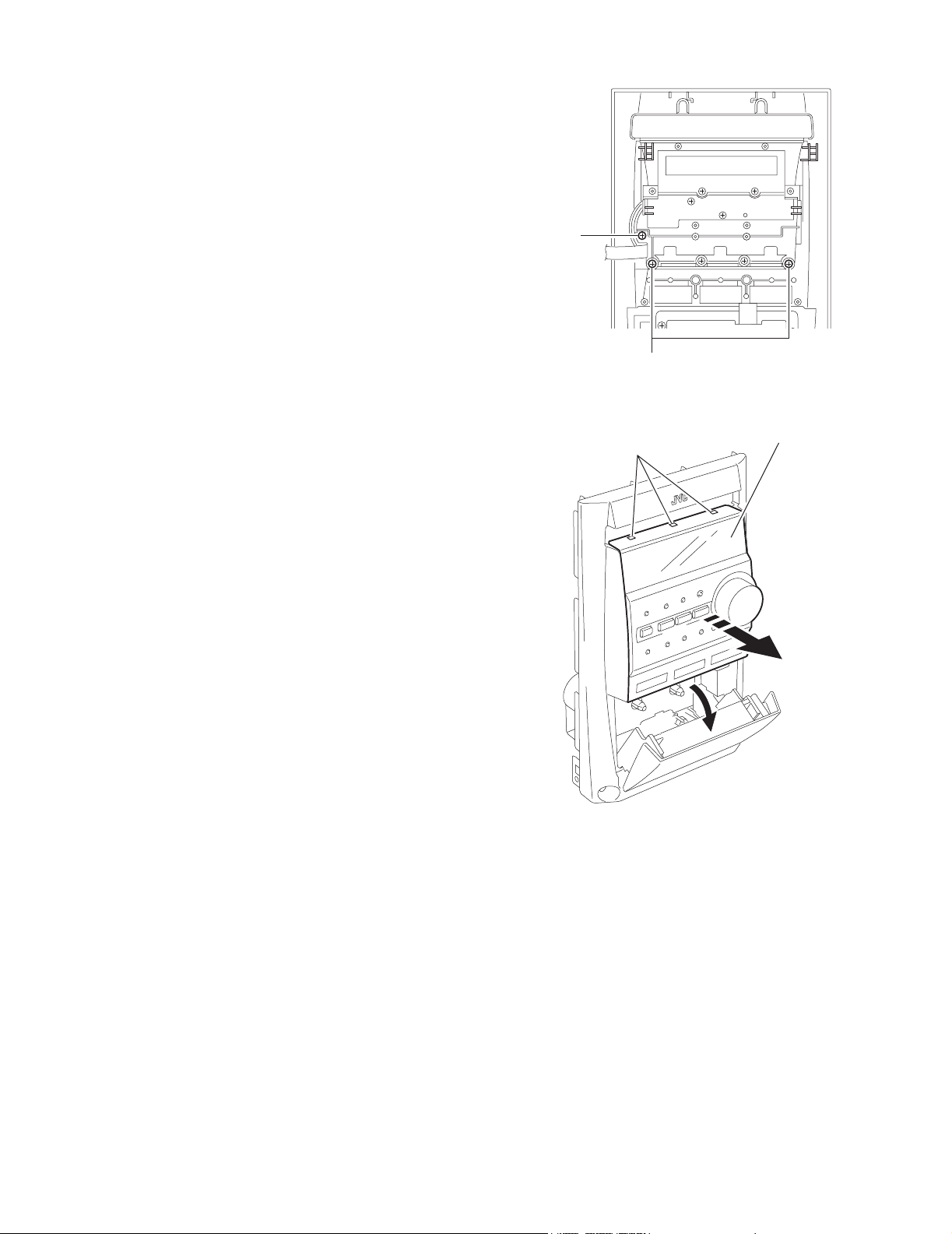
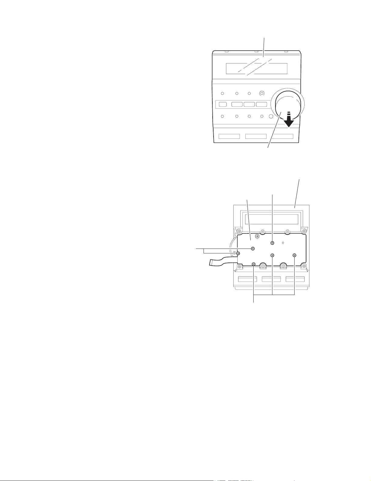
2.1.13 Removing the control panel assembly
(See Fig.19,20)
• Prior to performing the following procedure, remove the metal
cover, the front assembly, the switch board and the LCD board
assembly.
(1) Remove the three screws O attaching the control panel as-
sembly.
(2) Release the three joints i and open the cassette door
while pressing the cassette door, and then remove the control panel assembly in the direction of the arrow.
UX-J50
O
O
Fig.19
i
Cotrol panel assembly
Fig.20
(No.22032)1-13
UX-J50
2.1.14 Remiving the control board
(See Fig.21,22)
• Prior to performing the following procedure, remove the metal
cover, the front panel assembly, the switch board, the LCD
board assembly and the control panel assembly.
(1) Pull out the volume knob.
(2) Remove the six screws P attaching the control board.
Control panel assembly
Volume knob
Fig.21
Control panel assembly
P
Control board
P
P
Fig.22
1-14 (No.22032)
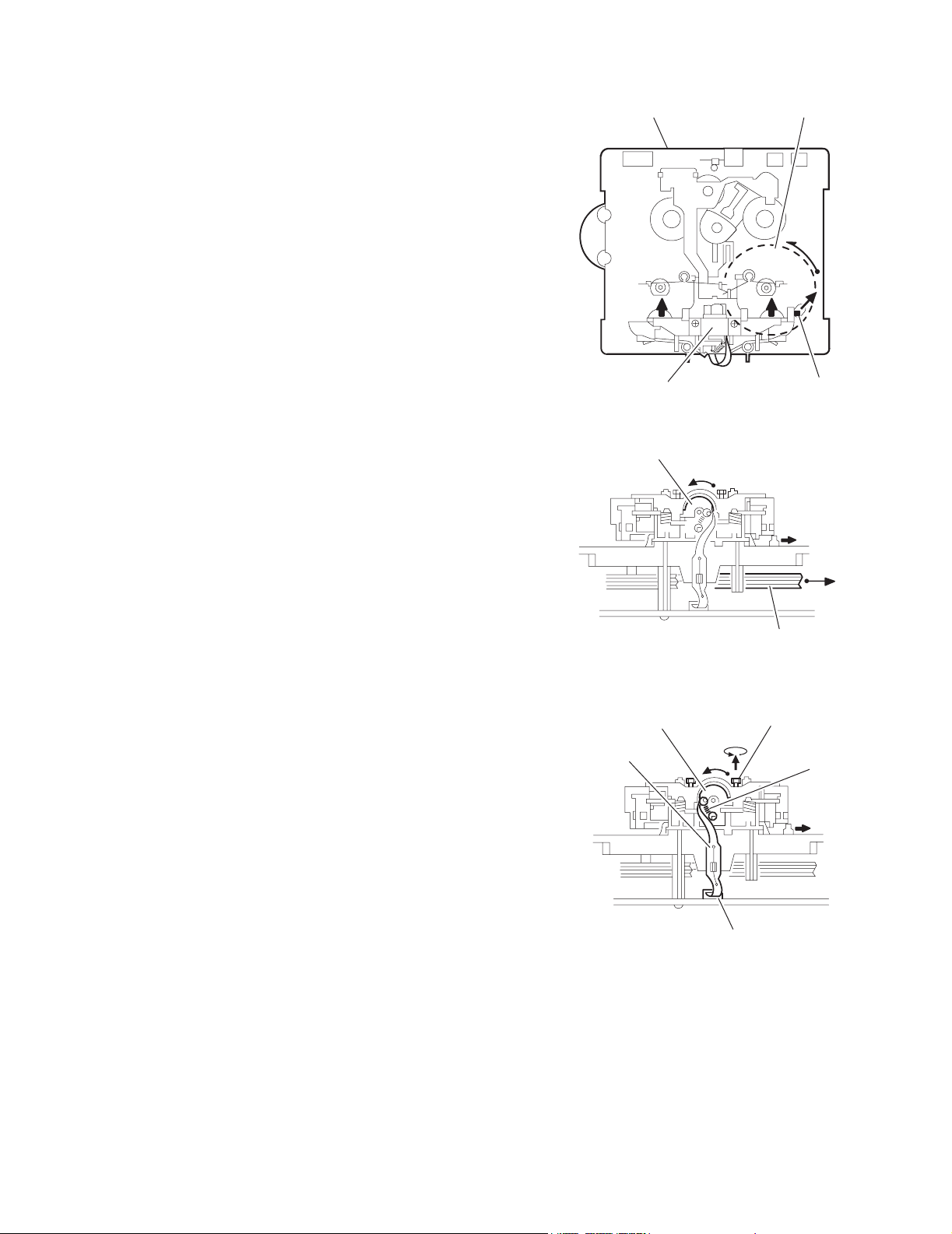
2.2 Cassette mechanism assembly
2.2.1 Removing the Play/Record & Clear head
(See Fig.1~3)
(1) While moving the trigger arm on the right side of the head
mount in the direction of the arrow, turn the flywheel R
counterclockwise until the head mount comes ahead and
clicks.
(2) The head turns counterclockwise as you turn the flywheel
R counterclockwise (See Fig.2 and 3).
(3) Disconnect the flexible wire from connector CN31 on the
head amplifier & mechanism control board.
(4) Remove the spring from the back of the head.
(5) Loosen the azimuth screw for reversing attaching the head.
(6) Remove the head on the front side of the head mount.
Cassette mechanism assembly
Fig.1
Head
UX-J50
Fly wheelR
Trigger armHead mount
Flexible wire
Fly wheel R
Fig.2
Azimuth screw
Head
for reversing
Spring
CN31
Head amplifer & mecha control board
Fig.3
(No.22032)1-15
UX-J50
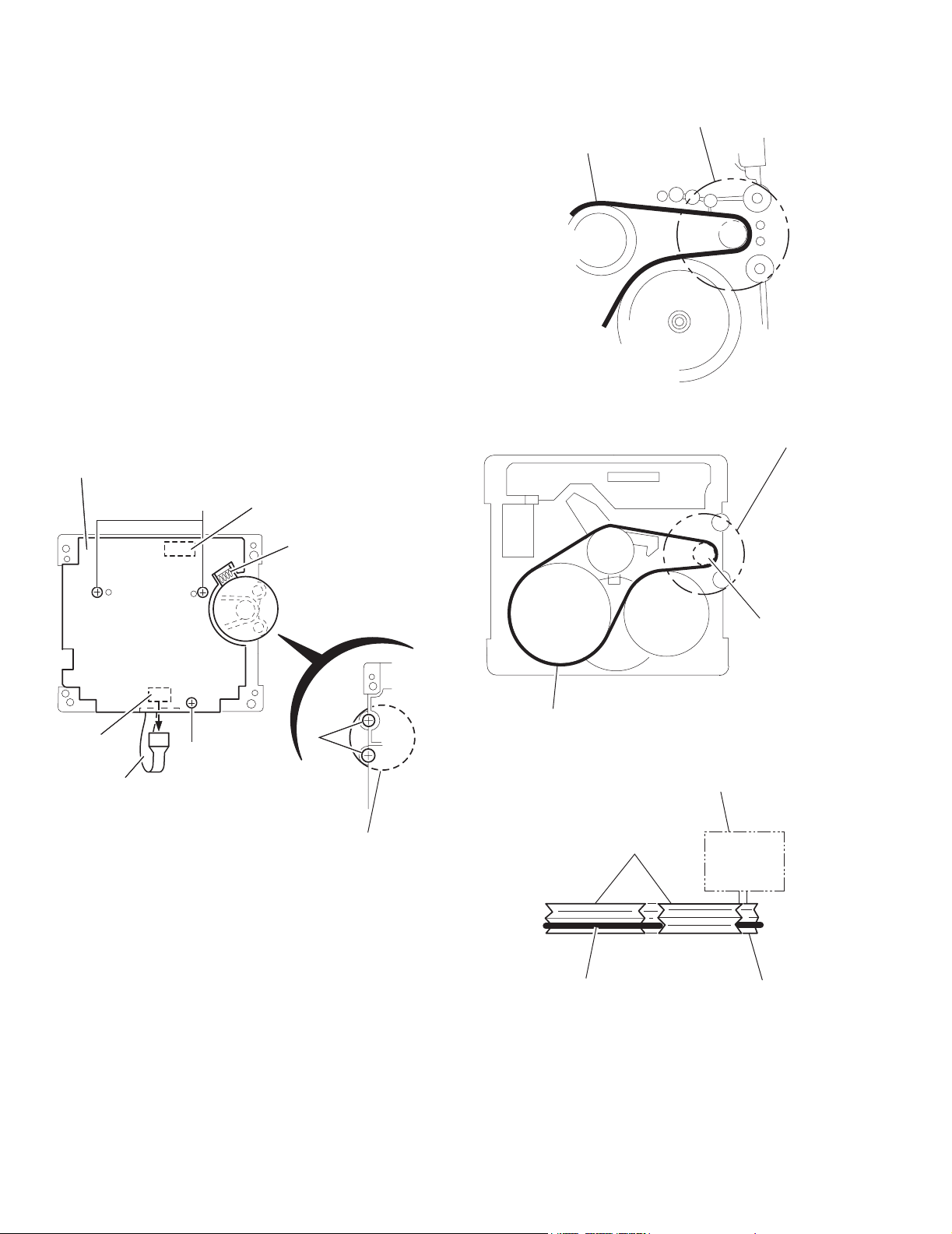
2.2.2 Removing the head amplifier & mechanism control board
(See Fig.4)
(1) Turn over the cassette mechanism assembly and remove
the three screws A attaching the head amplifier & mechanism control board.
(2) Disconnect the flexible wire from connector CN31 on the
head amplifier & mechanism control board.
(3) Disconnect connector CN32 of the head amplifier & mech-
anism control board from connector CN1 on the reel pulse
board.REFERENCE: If necessary, unsolder the 4-pin wire
soldered to the main motor.
2.2.3 Removing the main motor
(See Fig.4~7)
(1) Remove the two screws B .
(2) Half raise the motor and remove the capstan belt from the
motor pulley.
ATTENTION:
Be careful to keep the capstan belt from grease. When reassembling, refer to Fig.6 and 7 for attaching the capstan belt.
Head amplifier & mecha control board
Main motor assembly
Capstan belt
Fig.5
Main motor assembly
CN31
Flexible wire
A
AA
Fig.4
CN32
4pin wire
B
Main motor assembly
Motor pulley
Capstan belt
Fig.6
Main motor assembly
Fly wheel
1-16 (No.22032)
Capstan belt
Motor pulley
Fig.7
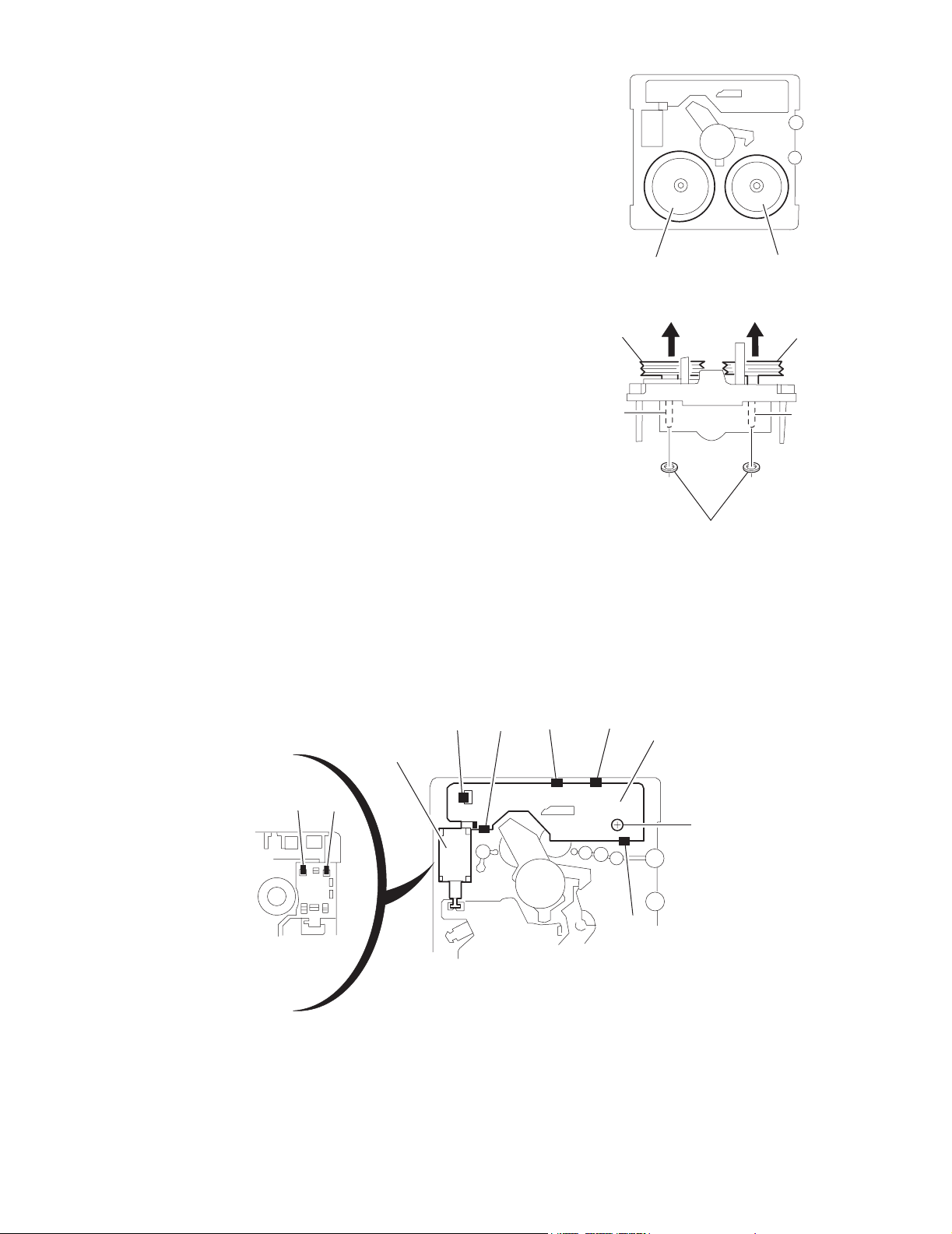
2.2.4 Removing the flywheel
(See Fig.8, 9)
• Prior to performing the following procedure, remove the head
amplifier & mechanism control board and the main motor assembly.
(1) From the front side of the cassette mechanism, remove the
slit washers attaching the capstan shaft L and R. Pull out
the flywheels backward.
UX-J50
Fly wheel R Fly wheel L
Fig.8
Fly wheel R
Capstan shaft R Capstan shaft L
Slit washer
Fig.9
2.2.5 Removing the reel pulse board and solenoid
(See Fig.10)
• Prior to performing the following procedure, remove the head amplifier & mechanism control board.
(1) Remove the screw C.
(2) Release the tab a, b, c, d and e retaining the reel pulse board.
(3) Release the tab f and g attaching the solenoid on the reel pulse board.
(4) The reel pulse board and the solenoid come off.
d
Reel pulse board
Solenoid
a
bc
Fly wheel L
g
f
C
e
Fig.10
(No.22032)1-17
UX-J50
r
r
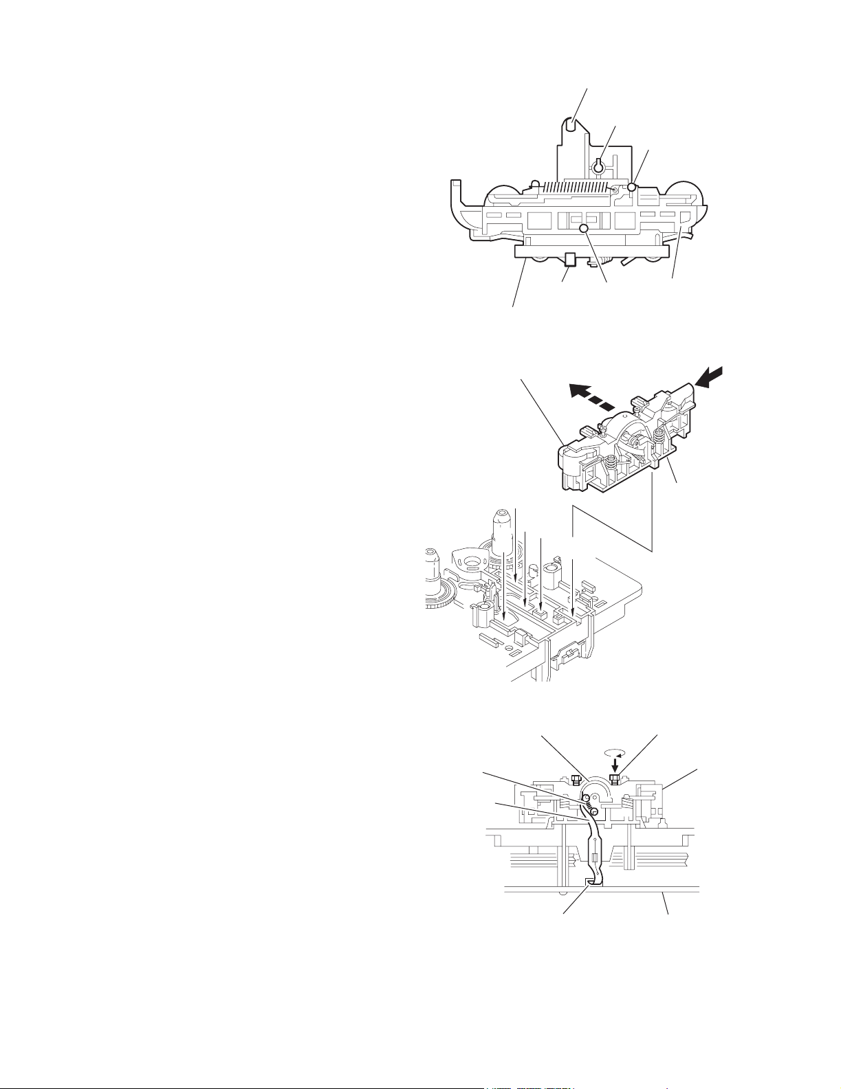
2.2.6 Reattaching the Play/ Record & Clear head
(See Fig.11~13)
(1) Reattaching the head mount assembly.
a) Change front of the direction cover of the head
mount assembly to the left (Turn the head forward).
b) Fit the bosses O', P', Q', U' and V' on the head mount
assembly to the holes P and V, the slots O, U and Q
of the mechanism sub assembly (See Fig.11 to 13).
CAUTION:
To remove the head mount assembly, turn the direction
cover to the left to disengage the gear. If the gear can not
be disengaged easily, push up the boss Q' slightly and
raise the rear side of the head mounts slightly to return
the direction lever to the reversing side.
(2) Tighten the azimuth screw for reversing.
(3) Reattach the spring from the back of the Play/ Record &
Clear head.
(4) Connect the flexible wire to connector CN31 on the head
amplifier & mechanism control board.
U' Q'
Head mount assembly
Head mount assembly
O'
Fig.11
P'
P'
V'
V'
Direction cove
Spring
Flexible wire
V
O
P
Q
Head
Direction cove
U
Fig.12
Azimuth screw for reversing
Head mount
1-18 (No.22032)
CN31
Fig.13
Head amplifier &
mechanism control board
3.1 Adjustment method
V
V
a
)
e
t
F
r
8
t
e
UX-J50
SECTION 3
Adjustment
Measurement Instruments Required for
Adjustment
1. Low frequency oscillator
This oscillator should have a capacity to output
0dBs to 600 at an oscillation frequency of
50Hz-20kHz.
2. Attenuator impedance : 600
3. Electronic voltmeter
4. Distortion meter
5. Frequency counter
6. Wow & flutter meter
7. Test tape
VT703L : Head azimuth
VT712 : Tape speed and running unevenness
(3kHz)
VT724 : Reference level (1kHz)
8. Blank tape
TYPE : AC-225
TYPE : AC-514
9. Torque gauge : For play and back tension
FWD(TW2111A), REV(TW2121a) and
FF/REW(TW2231A)
10. Test disc: CTS-1000
Measurement conditions
Power supply voltage
AC 230V ~ , 50Hz
Reference output : Speaker : 0.775V/4
: Headphone : 0.077V/32
Reference frequency and
input level ------------------------------ 1kHz, AUX : -8dBs
Measurement output terminal ------- at Speaker J3002
Load resistance --------------------------- 4
Radio Input signal
AM frequency --------------------------------------- 400Hz
AM modulation ---------------------------------------- 30%
FM frequency --------------------------------------- 400Hz
FM frequency deviation ------------------------ 22.5kHz
Tuner section
FM tuning range: 87.5MHz~108.00MHz
AM tuning range: 522kHz~1,629kHz
Voltage applied to tuner +B : DC5.7
VT : DC 12
Reference measurement
output 26.1mV(0.28V)/3
Input positions AM : Standard loop antenn
FM : TP1 (hot) and TP2 (GND
Standard measurement position of volume
Function switch to Tap
Beat cut switch to Cu
Super Bass/Active hyper Bass to OF
Bass Treble to Cente
Adjustment of main volume to reference output
VOL : 2
Precautions for measurement
1. Apply 30pF and 33k to the IF sweeper output
side and 0.082 F and 100k in series to the
sweeper input side.
2. The IF sweeper output level should be made as
low as possible within the adjustable range.
3. Since the IF sweeper is a fixed device, there is no
need to adjust this sweeper.
4. Since a ceramic oscillator is used, there is no need
to perform any MIX adjustment.
5. Since a fixed coil is used, there is no need to adjus
the FM tracking.
6. The input and output earth systems are separated.
In case of simultaneously measuring the voltage in
both of the input and output systems with an
electronic voltmeter for two channels, therefore, the
earth should be connected particularly carefully.
7. In the case of BTL connection amp., the minus
terminal of speaker is not for earthing. Therefore, b
sure not to connect any other earth terminal to this
terminal. This system is of an BTL system.
8. For connecting a dummy resistor when measuring
the output, use the wire with a greater code size.
9. Whenever any mixed tape is used, use the band
pass filter (DV-12).
(No.22032)1-19
 Loading...