


SERVICE MANUAL
MICRO COMPONENT SYSTEM
UX-H100
|
Area suffix |
|||
A ------------------------ |
|
|
Australia |
|
US ------------------------ |
|
|
Singapore |
|
UT ---------------------------- |
|
|
|
Taiwan |
UW ----------- |
Brazil,Mexico,Peru |
|||
UJ ---------------------- |
|
|
U.S.Military |
|
|
|
|
|
|
|
|
|
|
|
|
|
|
|
|
TABLE OF CONTENTS
1 PRECAUTION. . . . . . . . . . . . . . . . . . . . . . . . . . . . . . . . . . . . . . . . . . . . . . . . . . . . . . . . . . . . . . . . . . . . . . . . . 1-3 2 SPECIFIC SERVICE INSTRUCTIONS . . . . . . . . . . . . . . . . . . . . . . . . . . . . . . . . . . . . . . . . . . . . . . . . . . . . . . 1-6 3 DISASSEMBLY . . . . . . . . . . . . . . . . . . . . . . . . . . . . . . . . . . . . . . . . . . . . . . . . . . . . . . . . . . . . . . . . . . . . . . . 1-7 4 ADJUSTMENT . . . . . . . . . . . . . . . . . . . . . . . . . . . . . . . . . . . . . . . . . . . . . . . . . . . . . . . . . . . . . . . . . . . . . . . 1-16 5 TROUBLESHOOTING . . . . . . . . . . . . . . . . . . . . . . . . . . . . . . . . . . . . . . . . . . . . . . . . . . . . . . . . . . . . . . . . . 1-17
COPYRIGHT © 2004 Victor Company of Japan, Limited
No.MB248
2004/7
SPECIFICATION
Amplifier Section-CA-UXH100 |
Output Power |
|
10 W per channel, min. RMS, driven into 6 Ω at 1 kHz, |
|
|
|
|
|
with no more than 10% total harmonic distortion (IEC |
|
|
|
|
268-3) |
|
|
|
|
|
|
Speakers/Impedance |
|
6 Ω - 16 Ω |
|
|
|
|
|
|
Tuner |
FM tuning range |
|
FM 100 kHz intervals |
87.5 MHz-108.0 MHz |
|
|
|
|
|
|
|
|
FM 50 kHz intervals |
87.50 MHz-108.00 MHz |
|
|
|
|
|
|
AM tuning range |
|
AM 10 kHz intervals |
530 kHz-1 710 kHz |
|
|
|
|
|
|
|
|
AM 9 kHz intervals: |
531 kHz-1 710 kHz |
|
|
|
|
|
CD player |
Dynamic range |
|
85 dB |
|
|
|
|
|
|
|
Signal-to-noise ratio |
|
85 dB |
|
|
|
|
|
|
|
Wow and flutter |
|
Immeasurable |
|
|
|
|
||
Cassette deck |
Frequency response |
Normal (type I) |
100 Hz-10 000 Hz |
|
|
|
|
|
|
|
Wow and flutter |
|
0.35 % (WRMS) |
|
|
|
|
|
|
General |
Power requirement |
|
AC 110V-127V/220V-240 V , adjustable with the voltage |
|
|
|
|
|
selector, 50 Hz/60 Hz |
|
|
|
|
|
|
Power consumption |
|
38 W (at operation) 2 W (on standby) |
|
|
|
|
||
|
Dimensions (W/H/D) (approx.) |
144 mm × 255 mm × 277 mm |
||
|
|
|
|
|
|
Mass (approx.) |
|
2.9 kg |
|
|
|
|
|
|
Speaker Section-SP-UXH100 |
Type |
|
Full range Bass-reflex type |
|
|
|
|
|
|
|
Speakers |
|
10 cm cone × 1 |
|
|
|
|
||
|
Power handling capacity |
10 W |
||
|
|
|
|
|
|
Impedance |
|
6 Ω |
|
|
|
|
|
|
|
Frequency range |
|
100 Hz to 15 kHz |
|
|
|
|
||
|
Dimensions (W/H/D) (approx.) |
130 mm × 257 mm × 151 mm |
||
|
|
|
|
|
|
Mass (approx.) |
|
1.5 kg each |
|
|
|
|
|
|
Design and specifications are subject to change without notice.
1-2 (No.MB248)
SECTION 1 PRECAUTION
1.1Safety Precautions
(1)This design of this product contains special hardware and many circuits and components specially for safety purposes. For continued protection, no changes should be made to the original design unless authorized in writing by the manufacturer. Replacement parts must be identical to those used in the original circuits. Services should be performed by qualified personnel only.
(2)Alterations of the design or circuitry of the product should not be made. Any design alterations of the product should not be made. Any design alterations or additions will void the manufacturers warranty and will further relieve the manufacture of responsibility for personal injury or property damage resulting therefrom.
(3)Many electrical and mechanical parts in the products have special safety-related characteristics. These characteristics are often not evident from visual inspection nor can the protection afforded by them necessarily be obtained by using replacement components rated for higher voltage, wattage, etc. Replacement parts which have these special safety characteristics are identified in the Parts List of Service Manual. Electrical components having such features are identified by shading on the schematics and by (  ) on the Parts List in the Service Manual. The use of a substitute replacement which does not have the same safety characteristics as the recommended replacement parts shown in the Parts List of Service Manual may create shock, fire, or other hazards.
(4)The leads in the products are routed and dressed with ties, clamps, tubings, barriers and the like to be separated from live parts, high temperature parts, moving parts and/or sharp edges for the prevention of electric shock and fire hazard. When service is required, the original lead routing and dress should be observed, and it should be confirmed that they have been returned to normal, after reassembling.
(5)Leakage shock hazard testing
After reassembling the product, always perform an isolation check on the exposed metal parts of the product (antenna terminals, knobs, metal cabinet, screw heads, headphone jack, control shafts, etc.) to be sure the product is safe to operate without danger of electrical shock.Do not use a line isolation transformer during this check.
•Plug the AC line cord directly into the AC outlet. Using a "Leakage Current Tester", measure the leakage current from each exposed metal parts of the cabinet, particularly any exposed metal part having a return path to the chassis, to a known good earth ground. Any leakage current must not exceed 0.5mA AC (r.m.s.).
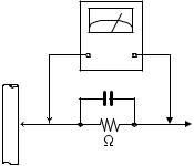
•Alternate check method
Plug the AC line cord directly into the AC outlet. Use an
AC voltmeter having, 1,000Ω per volt or more sensitivity in the following manner. Connect a 1,500Ω 10W resistor paralleled by a 0.15µF AC-type capacitor between an exposed metal part and a known good earth ground.
Measure the AC voltage across the resistor with the AC
voltmeter.
Move the resistor connection to each exposed metal part, particularly any exposed metal part having a return path to the chassis, and measure the AC voltage across the resistor. Now, reverse the plug in the AC outlet and repeat each measurement. Voltage measured any must not exceed 0.75 V AC (r.m.s.). This corresponds to 0.5 mA AC (r.m.s.).
AC VOLTMETER (Having 1000 ohms/volts,
or more sensitivity)
0.15 F AC TYPE
|
Place this |
|
probe on |
1500 10W |
each exposed |
metal part. |
Good earth ground
1.2Warning
(1)This equipment has been designed and manufactured to meet international safety standards.
(2)It is the legal responsibility of the repairer to ensure that these safety standards are maintained.
(3)Repairs must be made in accordance with the relevant safety standards.
(4)It is essential that safety critical components are replaced by approved parts.
(5)If mains voltage selector is provided, check setting for local voltage.
1.3Caution
Burrs formed during molding may be left over on some parts of the chassis.
Therefore, pay attention to such burrs in the case of preforming repair of this system.
1.4Critical parts for safety
In regard with component parts appearing on the silk-screen printed side (parts side) of the PWB diagrams, the parts that are printed over with black such as the resistor (  ), diode (
  ) and ICP (
  ) or identified by the "
  " mark nearby are critical for safety. When replacing them, be sure to use the parts of the same type and rating as specified by the manufacturer.
(This regulation dose not Except the J and C version)
(No.MB248)1-3
1.5Preventing static electricity
Electrostatic discharge (ESD), which occurs when static electricity stored in the body, fabric, etc. is discharged, can destroy the laser diode in the traverse unit (optical pickup). Take care to prevent this when performing repairs.
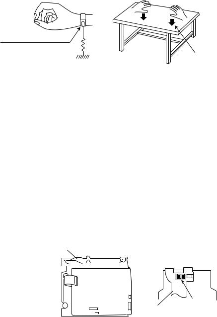
1.5.1Grounding to prevent damage by static electricity
Static electricity in the work area can destroy the optical pickup (laser diode) in devices such as laser products. Be careful to use proper grounding in the area where repairs are being performed.
(1)Ground the workbench
Ground the workbench by laying conductive material (such as a conductive sheet) or an iron plate over it before placing the traverse unit (optical pickup) on it.
(2)Ground yourself
Use an anti-static wrist strap to release any static electricity built up in your body.
(caption)
Anti-static wrist strap
1M
Conductive material (conductive sheet) or iron palate
(3)Handling the optical pickup
•In order to maintain quality during transport and before installation, both sides of the laser diode on the replacement optical pickup are shorted. After replacement, return the shorted parts to their original condition.
(Refer to the text.)
•Do not use a tester to check the condition of the laser diode in the optical pickup. The tester's internal power source can easily destroy the laser diode.
1.6Handling the traverse unit (optical pickup)
(1)Do not subject the traverse unit (optical pickup) to strong shocks, as it is a sensitive, complex unit.
(2)Cut off the shorted part of the flexible cable using nippers, etc. after replacing the optical pickup. For specific details, refer to the replacement procedure in the text. Remove the anti-static pin when replacing the traverse unit. Be careful not to take too long a time when attaching it to the connector.
(3)Handle the flexible cable carefully as it may break when subjected to strong force.
(4)I t is not possible to adjust the semi-fixed resistor that adjusts the laser power. Do not turn it.
1.7Attention when traverse unit is decomposed
*Please refer to "Disassembly method" in the text for the pickup unit.
•Apply solder to the short land sections before the flexible wire is disconnected from the connecto on the servo board. (If the flexible wire is disconnected without applying solder, the pickup may be destroyed by static electricity.)
•In the assembly, be sure to remove solder from the short land sections after connecting the flexible wire.
CD changer unit
Soldering
Flexible cable
1-4 (No.MB248)
1.8Important for laser products
1.CLASS 1 LASER PRODUCT
2.DANGER : Invisible laser radiation when open and inter lock failed or defeated. Avoid direct exposure to beam.
3.CAUTION : There are no serviceable parts inside the Laser Unit. Do not disassemble the Laser Unit. Replace the complete Laser Unit if it malfunctions.
4.CAUTION : The CD,MD and DVD player uses invisible laser radiation and is equipped with safety switches which prevent emission of radiation when the drawer is open and the safety interlocks have failed or are defeated. It is dangerous to defeat the safety switches.
5.CAUTION : If safety switches malfunction, the laser is able
to function.
6.CAUTION : Use of controls, adjustments or performance of procedures other than those specified here in may result in hazardous radiation exposure.
! |
|
Please use enough caution not to |
|||
|
|
see the beam directly or touch it |
|||
|
|
in case of an adjustment or operation |
|||
|
|
check. |
|||
|
|
|
|
|
|
|
|
|
|
|
|
|
|
|
|
|
|
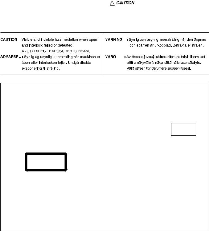
REPRODUCTION AND POSITION OF LABELS
WARNING LABEL
CLASS 1
LASER PRODUCT
CAUTION : Visible and Invisible |
ADVARSEL : Synlig og usynlig |
|
VARNING |
: |
Synlig |
och |
|||||||||||
laser radiation when open and |
laserstråling |
når maskinen |
er |
|
osynling |
laserstrålning |
när |
||||||||||
interlock |
failed or defeated. |
åben eller interlocken fejeler. |
|
den öppnas och spärren är |
|||||||||||||
AVOID DIRECT EXPOSURE TO |
Undgå |
direkte eksponering til |
|
urkopplad. |
Betrakta |
ej |
|||||||||||
BEAM. |
|
(e) |
stråling. |
|
|
|
|
|
(d) |
|
strålen. |
|
|
|
(s) |
||
|
|
|
|
|
|
|
|
||||||||||
|
|
|
|
|
|
||||||||||||
|
|
CAUTION : Visible and Invisible |
|
VARO : Avattaessa ja suojalukitus |
|
||||||||||||
|
|
laser radiation when open and |
|
ohitettuna tai viallisena olet alttiina |
|
||||||||||||
|
|
interlock |
failed |
or |
defeated. |
|
näkyvälle |
ja |
näkymättömälle |
|
|||||||
|
|
AVOID DIRECT EXPOSURE TO |
|
lasersäteilylle. |
Vältä |
säteen |
|
||||||||||
|
|
BEAM. |
|
|
|
|
(e) |
|
kohdistumista suoraan itseesi. (f) |
|
|||||||
|
|
|
|
|
|
|
|
|
|||||||||
|
|
|
|
|
|
|
|
|
|||||||||
|
|
VARNING |
: |
Synlig |
och |
|
ADVARSEL : Synlig og usynlig |
|
|||||||||
|
|
osynling |
laserstrålning |
när |
|
laserstråling når |
maskinen er |
|
|||||||||
|
|
den öppnas och spärren är |
|
åben |
eller |
interlocken |
fejeler. |
|
|||||||||
|
|
urkopplad. |
|
Betrakta |
ej |
|
Undgå direkte eksponering til |
|
|||||||||
|
|
strålen. |
|
|
|
|
(s) |
|
stråling. |
|
|
|
(d) |
|
|||
|
|
|
|
|
|
|
|
|
|
|
|
|
|
|
|
|
|
VARO : Avattaessa ja suojalukitus ohitettuna tai viallisena olet alttiina näkyvälle ja näkymättömälle lasersäteilylle. Vältä säteen kohdistumista suoraan itseesi. (f)
(No.MB248)1-5
SECTION 2
SPECIFIC SERVICE INSTRUCTIONS
This service manual does not describe SPECIFIC SERVICE INSTRUCTIONS.
1-6 (No.MB248)
SECTION 3
DISASSEMBLY
3.1Disassembly of the main blocks of the set
3.1.1Replacing the fuses (See Fig.1)
•Prior to performing the following procedure, remove the rear cover.
(1) Replace the fuses inside.
Caution:
Be sure to use fuses with the specified ratings.
Fuse (F901) 800MAL 250V
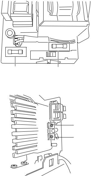
3.1.2 Replacing the power IC (See Fig.2)
•Prior to performing the following procedure, remove the rear cover.
(1)Remove the two screws A from the heat sink between the power IC.
(2)Remove the solder fixing the power IC.
Fuse (F902)
T315MAL 250V
Fig.1
 A
A
Fig.2
(No.MB248)1-7
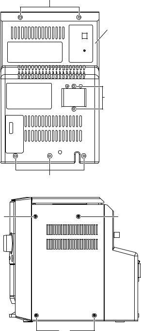
3.1.3 Removing the rear cover (See Fig.3 and 4)
(1)Remove the seven screws C that retain the rear cover from the back of the body.
(2)Remove the eight screws D that retain the rear cover from the two sides of the body.
(3)Remove the rear cover from the body by pulling it toward the back.
Caution:
The FM terminal wire (inside) must be pulled out, while removing the rear cover.
C
Rear cover
C
C
Fig.3
D D
D
Fig.4
1-8 (No.MB248)
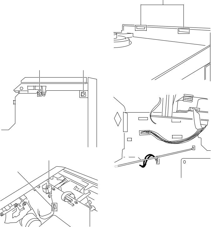
3.1.4Removing the CD chassis assembly (See Fig.5 to 8)
•Prior to performing the following procedures, remove the rear cover.
(1)Remove a screw E retaining the main board onto the CD chassis.
(2)Disconnect the two FFC cables X1, X2 from the connectors CN704, CN703 on the CD board.
(3)Disengage the claws F on both sides of the body, while moving the CD chassis assembly downward and backward.
(4)Before you take away the CD chassis assembly, you must disconnect the wire from the connector CN204 on the main board. (Fig.8)
Caution:
You must ensure that the two claws of the CD chassis's top G are disengaged, while moving the CD chassis assembly.
G
E F
Fig.7
Cassette mechanism
Fig.5
X1
X2
Fig.8
Fig.6
(No.MB248)1-9

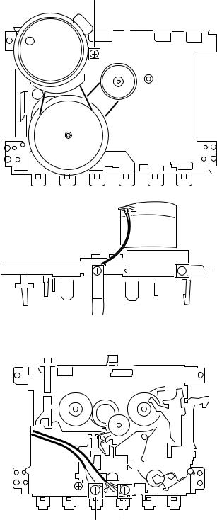
3.1.5 Removing the CD mechanism |
|
(See Fig.9 to 13) |
|
• Prior to performing the following procedures, remove the rear |
Y3 |
cover. |
•Also remove the CD chassis assembly.
(1)Remove the three screws Y1 retaining the CD board.
(2)Disconnect the FFC cable Y2 from the connector CN701.
(3)Disconnect the two parallel wires Y3 from the connector.
(4)Remove the four screws Y4 with washers retaining the CD mechanism.
Y1 |
Fig.12 |
|
Y4 |
Fig.9
Y2 |
Fig.10
Y3 |
Fig.13 |
|
Fig.11
1-10 (No.MB248)
3.1.6Removing the bottom base assembly (See Fig.14 to 18)
•Prior to performing the following procedures, remove the rear cover.
•Also remove the CD chassis assembly.
(1)Remove the two screws H retaining the front panel assembly.
(2)Disengage the wire Q that fix the cassette deck wire.
(3)Disconnect the cassette head wire Z1 and the cassette motor wire Z2 of power supply from the connectors CN202, CN203, and then disconnect the AUX IN connecting wire Z3 from the connector TP1.
(4)Disengage the claws I on both sides of the front cabinet assembly and then move the bottom base assembly toward the back.
Caution:
You must ensure that the 30 pin connector CN201 is disconnected (See Fig.15).
H
Fig.16
Front panel
Circuit board
Q
Fig.14
CN201
I
Fig.17
Z1 |
Z2 |
Z3 |
||
|
|
|
|
|
|
|
|
|
|
|
|
|
|
|
Fig.15
Fig.18
(No.MB248)1-11
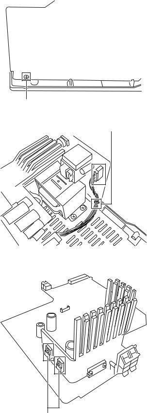
3.1.7 Removing the main board (See Fig.19 and 20)
•Prior to performing the following procedures, remove the rear cover.
•Also remove the CD chassis assembly.
•Also remove the bottom base assembly.
(1)Disengage the wire M and then disconnect the parallel wire from the connectors CN902 (See Fig.20).
(2)Removing the screw N retaining the main board onto the bottom base.
Main board
Bottom base
N
Fig.19
M |
Fig.20
3.1.8 Replacing the 3-pin regulator (See Fig.21)
•Prior to performing the following procedures, remove the rear cover.
•Also remove the CD chassis assembly.
•Also remove the main board assembly.
(1)Remove the two screws P retaining 3-pin regulator.
(2)Remove the solder fixing the 3-pin regulator Q216, .
P
Fig.21
1-12 (No.MB248)

3.1.9Removing the cassette deck mechanism (See Fig.22 and 23)
•Prior to performing the following procedures, remove the rear cover.
•Also remove the CD chassis assembly.
•Also remove the bottom base assembly.
(1)Remove the four screws J retaining the cassette deck mechanism from the back of the front cabinet assembly.
Caution: |
J |
J |
You must press the eject key before you remove the cassette |
|
|
deck mechanism. |
|
|
Fig.22
Fig.23
(No.MB248)1-13
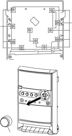
3.1.10 Removing the display/control board assembly (See Fig.24 and 25)
•Prior to performing the following procedures, remove the rear cover.
•Also remove the CD chassis assembly.
(1)Remove the eleven screws K retaining the display/control board assembly from the back of the front cabinet assembly.
Caution:
The display/control board may be taken out when the volume knob has been taken away.
K
K
Fig.24
Front panel assembly
Volume knob
Fig.25
1-14 (No.MB248)
3.1.11Removing the cassette deck main motor, and replacing the main belt (See Fig.26 and 27)
•Prior to performing the following procedures, remove the rear cover.
•Also remove the CD chassis assembly.
•Also remove the bottom base assembly.
(1)Remove the four screws J retaining the cassette deck mechanism. (See Fig.22)
(2)Remove the cassette deck mechanism.
(3)Remove the two screws L retaining the main motor from the back side of the cassette deck and the top side of the cassette deck.
Caution:
After attaching the main motor, check the orientation of the motor and the polarity of the wires.
(4)Form the backside of the cassette deck, remove the main motor and the main belt.
L
Fig.26
L
Fig.27
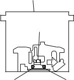
3.1.12 Removing the cassette deck head (See Fig.28)
•Prior to performing the following procedures, remove the rear cover.
•Also remove the CD chassis assembly.
•Also remove the bottom base assembly.
(1)Remove the four screws J that retain the cassette deck mechanism. (See Fig.22)
(2)Remove the cassette deck mechanism and place it so that the front side faces up.
(3)Remove the solder from the bottom side of the head terminal and disconnect the wire.
(4)Remove the screw U that retains the head.
(5)Remove the screw W that retains the head.
(6)Hold the head and slide it in the direction of the arrow to re-
move it.
W U
Fig.28
(No.MB248)1-15
SECTION 4
ADJUSTMENT
4.1Arrangement of adjusting positions
Cassette deck mechanism (Front side)
REC/PB Head |
(Deck-B) |
Head azimuth screw |
Head azimuth screw |
(Forward side) |
(Reverse side) |
4.2Tape recorder section
Items |
Measurement |
Measurement method |
Standard |
Adjusting |
|
conditions |
values |
positions |
|||
|
|
||||
Cassette Head |
Test tape |
1.Playback the test tape VT703 (10KHz) or |
Maximum |
Adjust the |
|
Azimuth |
: VT703 (10kHz) |
equivalent. |
output |
head azimuth |
|
Alignments |
Measurement |
2.Adjust the head azimuth screw to obtain |
|
screw only |
|
|
output terminal |
maximum output and both output of L/R |
|
when the head |
|
|
|
has been |
|||
|
: Left and Right |
is in 3dB. |
|
||
|
|
changed. |
|||
|
speaker output |
3.Put on the screw lock paint after alignments. |
|
||
|
|
|
|
||
|
(6-ohm loaded) |
|
|
|
|
|
or |
|
|
|
|
|
Headphone Output |
|
|
|
|
|
(32-ohm loaded) |
|
|
|
|
|
|
|
|
|
|
Recording Bias |
Test tape |
1.Insert the recording tape in deck-B. |
82kHz+/-3kHz |
Use the High- |
|
Frequency |
: TYPE I AC-514 |
2.Starting the recording. |
|
Impedance |
|
Alignment |
Measurement |
3.Adjust the oscillation frequency to |
|
Probe or |
|
|
output terminal |
82KHz+/-3KHz by core of Oscillation coil |
|
Frequency |
|
|
: Erase head |
of T201. |
|
counter input. |
|
|
terminal |
|
|
|
|
|
(CN202 2 th Pin) |
|
|
|
|
|
|
|
|
|
4.3Tuner section
|
Items |
Measurement |
Measurement method |
Standard |
Adjusting |
|
conditions |
values |
positions |
||
|
|
|
|||
|
AM Tracking |
Input signal |
1.Set the Signal Generator signal to 1629KHz |
|
Adjust the OSC |
|
Alignments |
: 1629kHz |
the feedto Loop Antenna. |
V.T |
coil only when |
|
the AM coil block |
||||
|
|
600kHz |
2.Receiving the signal and the adjust the OSC |
: 4.7V+/-0.05V |
|
|
|
has been |
|||
|
|
Adjustment point |
|||
|
|
coil (404) obtain the. VT is 4.7V +/-0.05V. |
|
changed. |
|
|
|
: Antenna coil (T2) |
3.Change the receiving frequency to 603KHz. |
|
|
|
|
|
|
||
|
|
|
4.Adjust the Antenna coil ( L102 ) obtain |
Maximum |
|
|
|
|
maximum sensitivity |
sensitivity |
|
|
|
|
(Adjust the SSG output to out of AGC range.) |
|
|
|
|
|
|
|
|
|
AM IFT |
Input signal |
1.Set the receiving frequency to 522KHz. |
Maximum |
Adjust the IFT |
|
Alignments |
: 522kHz |
2.Feed the 450KHz signal to AM antenna input. |
output |
only when the |
|
|
Adjustment point |
3.Adjust the IFT BlockT1 obtain to maximum |
|
IFT block has |
|
|
|
been changed. |
||
|
|
: IFT (T101) |
output. |
|
|
|
|
|
|
||
|
|
|
(Adjust the SSG output to out of AGC range.) |
|
|
|
|
|
|
|
|
|
Note: The adjustment of CD section is not required. |
|
|
||
1-16 (No.MB248) |
|
|
|
|
|
SECTION 5
TROUBLESHOOTING
This service manual does not describe TROUBLESHOOTING.
(No.MB248)1-17
 Loading...