


 Loading...
CD/CDR MULTIPLE COMPACT DISC RECORDER
XL-R5000BK
CD REC |
SYNCHRO |
DISPLAY POWER |
CD EDIT |
FINALIZE |
MENU |
|
|
|
CD 1 |
1 |
2 |
3 |
|
|
|
|
CD 2 |
4 |
5 |
6 |
|
|
|
|
CD 3 |
7 |
8 |
9 |
|
|
|
CONTROL |
|
10 |
+10 |
CD |
CDR |
PLAY MODE |
REPEAT |
SET |
CANCEL |
|
PITCH + |
|
|
|
PITCH 0 |
|
|
|
|
|
REC |
SHIFT |
PITCH – |
REC MUTING |
|
|
|
||
REMOTE CONTROL
RM-SXLR5000J
XL - R5000 CD/CDR MULTIPLE COMPACT DISC RECORDER |
|
|
|
|
|
|
REC LEVEL |
|||||
|
|
|
|
|
|
|
|
|
|
EJECT |
|
|
|
|
|
|
3-CD |
|
REC SOURCE SELECTOR |
|
|
|
|
|
|
|
|
|
|
DIGITAL |
CD |
LINE |
MIC |
FINALIZE |
|
|
|
|
|
|
|
|
PLAY & EXCHANGE |
|
MIN |
MAX |
|||||
|
|
|
|
|
|
|
|
|
|
|
||
|
|
|
|
|
|
|
MIXING |
|
|
|
|
|
CLOCK/ |
PLAY |
CD CONTROL |
|
|
|
|
|
CDR CONTROL |
MIX BALANCE |
PHONES LEVEL |
||
CD EDIT |
CD REC |
|
|
|
|
REC |
SYNCHRO |
REC |
|
|
||
TIMER |
MODE |
MENU |
|
|
MULTI JOG |
MUTING |
|
|
||||
|
|
|
DISPLAY |
|
|
|
|
|
|
|
||
STANDBY |
|
|
|
|
|
|
|
|
|
|
|
|
|
|
|
|
|
|
|
– |
+ |
|
LINE |
CD |
MIN MAX |
|
|
|
|
|
|
|
|
MIC |
LINE |
|
||
|
|
|
CANCEL |
SET |
|
|
|
|
MIC |
PHONES |
||
POWER
INSTRUCTIONS
For Customer Use:
Enter below the Model No. and Serial No. which are located on the rear, bottom or side of the cabinet. Retain this information for future reference.
Model No.
Serial No.
LVT0452-001C
[ J/C/B/U ]
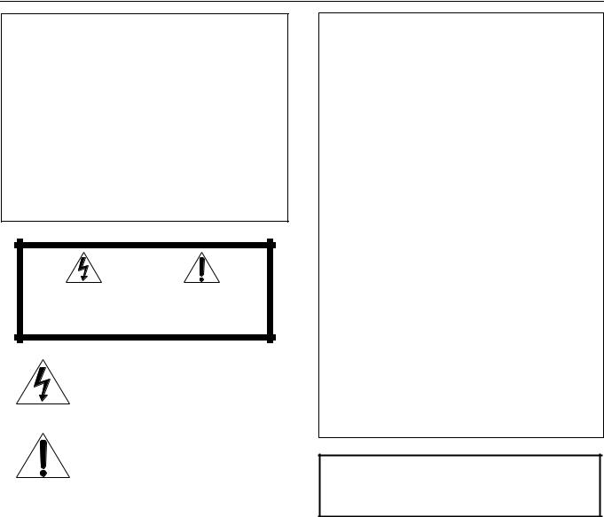
Warnings, Cautions and Others
For U.S.A.
This equipment has been tested and found to comply with the limits for a Class B digital device, pursuant to part 15 of the FCC Rules. These limits are designed to provide reasonable protection against harmful interference in a residential installation.
This equipment generates, uses and can radiate radio frequency energy and, if not installed and used in accordance with the instructions, may cause harmful interference to radio communications. However, there is no guarantee that interference will not occur in a particular installation. If this equipment does cause harmful interference to radio or television reception, which can be determined by turning the equipment off and on, the user is encouraged to try to correct the interference by one or more of the following measures:
Reorient or relocate the receiving antenna.
Increase the separation between the equipment and receiver. Connect the equipment into an outlet on a circuit different from that to which the receiver is connected.
Consult the dealer or an experienced radio/TV technician for help.
|
|
CAUTION |
|
|
|
RISK OF ELECTRIC SHOCK |
|
|
|
DO NOT OPEN |
|
|
|
|
|
|
|
|
|
CAUTION: |
TO REDUCE THE RISK OF ELECTRIC SHOCK, |
||
|
DO NOT REMOVE COVER (OR BACK). |
||
|
NO USER SERVICEABLE PARTS INSIDE. |
||
REFER SERVICING TO QUALIFIED SERVICE PERSONNEL.
The lightning flash with arrowhead symbol, within an equilateral triangle is intended to alert the user to the presence of uninsulated "dangerous voltage" within the product's enclosure that may be of sufficient magnitude to constitute a risk of electric shock to persons.
The exclamation point within an equilateral triangle is intended to alert the user to the presence of important operating and maintenance (servicing) instructions in the literature accompanying the appliance.
IMPORTANT for the U.K.
DO NOT cut off the mains plug from this equipment. If the plug fitted is not suitable for the power points in your home or the cable is too short to reach a power point, then obtain an appropriate safety approved extension lead or consult your dealer.
BE SURE to replace the fuse only with an identical approved type, as originally fitted.
If nontheless the mains plug is cut off ensure to remove the fuse and dispose of the plug immediately, to avoid a possible shock hazard by inadvertent connection to the mains supply.
If this product is not supplied fitted with a mains plug then follow the instructions given below:
IMPORTANT.
DO NOT make any connection to the terminal which is marked with the letter E or by the safety earth symbol or coloured green or green-and-yellow.
The wires in the mains lead on this product are coloured in accordance with the following code:
Blue : Neutral
Brown : Live
As these colours may not correspond with the coloured markings identifying the terminals in your plug proceed as follows:
The wire which is coloured blue must be connected to the terminal which is marked with the letter N or coloured black.
The wire which is coloured brown must be connected to the terminal which is marked with the letter L or coloured red.
IF IN DOUBT - CONSULT A COMPETENT ELECTRICIAN.
WARNING: TO REDUCE THE RISK OF FIRE OR ELECTRIC SHOCK, DO NOT EXPOSE THIS APPLIANCE TO RAIN OR MOISTURE.
G-1

For Canada & USA
Caution –– POWER switch!
Disconnect the mains plug to shut the power off completely. The POWER switch in any position does not disconnect the mains line. The power can be remote controlled.
Attention –– Commutateur POWER!
Déconnecter la fiche de secteur pour couper complètement le courant. Le commutateur POWER ne coupe jamais complètement la ligne de secteur, quelle que soit sa position. Le courant peut être télécommandé modèle.
For other countries
Caution –– |
switch! |
Disconnect the mains plug to shut the power off completely. The switch in any position does not disconnect the mains line. The power can be remote controlled.
CAUTION
To reduce the risk of electrical shocks, fire, etc.:
1.Do not remove screws, covers or cabinet.
2.Do not expose this appliance to rain or moisture.
ATTENTION
Afin d'éviter tout risque d'électrocution, d'incendie, etc.:
1.Ne pas enlever les vis ni les panneaux et ne pas ouvrir le coffret de l'appareil.
2.Ne pas exposer l'appareil à la pluie ni à l'humidité.
For Canada/pour le Canada
THIS DIGITAL APPARATUS DOES NOT EXCEED THE CLASS B LIMITS FOR RADIO NOISE EMISSIONS FROM DIGITAL APPARATUS AS SET OUT IN THE INTERFERENCE-CAUSING EQUIPMENT STANDARD ENTITLED "DIGITAL APPARATUS", ICES-003 OF THE DEPARTMENT OF COMMUNICATIONS.
CET APPAREIL NUMERIQUE RESPECTE LES LIMITES DE BRUITS RADIOELECTRIQUES APPLICABLES AUX APPAREILS NUMERIQUES DE CLASSE B PRESCRITES DANS LA NORME SUR LE MATERIEL BROUILLEUR: "APPAREILS NUMERIQUES", NMB-003 EDICTEE PAR LE MINISTRE DES COMMUNICATIONS.
For Canada/pour le Canada
CAUTION: TO PREVENT ELECTRIC SHOCK, MATCH WIDE BLADE OF PLUG TO WIDE SLOT, FULLY INSERT
ATTENTION: POUR EVITER LES CHOCS ELECTRIQUES, INTRODUIRE LA LAME LA PLUS LARGE DE LA FICHE DANS LA BORNE CORRESPONDANTE DE LA PRISE ET POUSSER JUSQUAU FOND
G-2
REPRODUCTION OF LABELS (Except for Canada & USA)
1 CLASSIFICATION LABEL, PLACED ON REAR ENCLOSURE
CLASS 1
LASER PRODUCT
2 WARNING LABEL, PLACED INSIDE THE UNIT
CAUTION: Invisible |
laser |
radiation when open |
and |
interlock failed or defeated. |
|
AVOID DIRECT EXPOSURE |
|
TO BEAM. |
(e) |
|
|
VARNING: Osynlig laserstrålning när denna del är öppnad och spärren är urkopplad. Betrakta ej strålen. (s)
ADVARSEL: Usynlig laserstråling ved åbning, når sikkerhedsafbrydere er ude af funktion. Undgå udsættelse for stråling (d)
VARO: Avattaessa ja suojalukitus ohitettaessa olet alttiina näkymättömälle lasersäteilylle. Älä katso säteeseen. (f)
IMPORTANT FOR LASER PRODUCTS
IMPORTANT POUR LES PRODUITS LASER
(For Canada & USA)
1.CLASS 1 LASER PRODUCT
2.DANGER: Invisible laser radiation when open and interlock failed or defeated. Avoid direct exposure to beam.
3.CAUTION: Do not open the top cover. There are no user serviceable parts inside the Unit; leave all servicing to qualified service personnel.
1.PRODUIT LASER CLASSE 1
2.ATTENTION: Radiation laser visible quand l’appareil est ouvert ou que le verrouillage est en panne ou désactivé. Eviter une exposition directe au rayon.
3.ATTENTION: Ne pas ouvrir le couvercle du dessus. Il n'y a aucune pièce utilisable à l'intérieur. Laisser à un personnel qualifié le soin de réparer votre appareil.
(For other countries)
1.CLASS 1 LASER PRODUCT
2.CAUTION: Invisible laser radiation when open and interlock failed or defeated. Avoid direct exposure to beam.
3.CAUTION: Do not open the top cover. There are no user serviceable parts inside the Unit; leave all servicing to qualified service personnel.
G-3
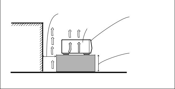
Caution: Proper Ventilation
To avoide risk of electric shock and fire and to protect from damage.
Locate the apparatus as follows:
Front: |
No obstructions open spacing. |
Sides: |
No obstructions in 3 cm from the sides. |
Top: |
No obstructions in 5 cm from the top. |
Back: |
No obstructions in 15 cm from the back |
Bottom: |
No obstructions, place on the level surface. |
|
|
|
Spacing 15 cm or more |
Front
Wall or obstructions |
XL-R5000BK
Stand height 15 cm or more
Floor
G-4

Table of Contents
Introduction ....................................................... |
1 |
Table of Contents .............................................. |
1 |
Precautions ........................................................ |
2 |
Features ............................................................. |
2 |
Connections ....................................................... |
3 |
Analog Connections .................................................................... |
3 |
Digital Connections..................................................................... |
4 |
Names of the Parts ............................................ |
5 |
Main Unit .................................................................................... |
5 |
Display Window.......................................................................... |
7 |
Remote Control ........................................................................... |
8 |
Using the Remote Control ................................ |
9 |
Installing the batteries ................................................................. |
9 |
How to use the remote control correctly ..................................... |
9 |
Power ON/STANDBY Operations ................ |
10 |
Turning the power on and putting in standby ........................... |
10 |
Listening to CDs .............................................. |
11 |
Continuous Playback of the 3-CD Changer (playing |
|
the loaded discs through once each)...................................... |
11 |
CDR Playback Operations ........................................................ |
12 |
Using the Remote Control to Control Playback........................ |
12 |
Direct Playback from a Specific Track ..................................... |
13 |
Forward and Reverse Search..................................................... |
13 |
Skipping Tracks ........................................................................ |
14 |
Repeat Playback ........................................................................ |
14 |
Random Playback...................................................................... |
15 |
CD Playback Pitch Control ....................................................... |
15 |
Disc Lock Function ................................................................... |
15 |
Program Playback ..................................................................... |
16 |
Program playback using the remote control.............................. |
17 |
Recording onto CD-R and CD-RW ............... |
18 |
Manual Recording ..................................................................... |
18 |
Synchronized Recording of 3-CD Changer Playback............... |
20 |
Listening Edit Recording .......................................................... |
21 |
Program Edit Recording............................................................ |
22 |
3-CD Changer to CDR Recording Options............................... |
23 |
Setting the unit to perform high-speed recording ..................... |
23 |
Setting the auto track spacing function ..................................... |
24 |
Synchronized Start Recording of External Components .......... |
25 |
Mixed Input Recording ............................................................. |
26 |
Special Recording Edit Operations .............. |
27 |
Skipping a Recorded Track on a CD-R or CD-RW |
|
(Track Skip)........................................................................... |
27 |
Erasing a track or tracks (ERASE function) ............................. |
27 |
Erasing all the tracks (DISC ERASE function) ........................ |
28 |
Finalization................................................................................ |
29 |
Making recording possible again on a finalized CD-RW |
|
(UNFINALIZE function) ...................................................... |
30 |
Bypassing the FS Converter (Sampling Frequency Converter) |
|
for More Efficient Digital Recording .................................... |
30 |
Setting Up Synchronized Start Recording for External |
|
Digital Sources (CD, MD, and DAT only) ........................... |
31 |
Resetting the Unit to the Factory Default Settings.................... |
32 |
Setting the Clock ............................................. |
33 |
Setting the Present Time ........................................................... |
33 |
Timer Operations ............................................ |
34 |
Timer Play (wake-up play)........................................................ |
34 |
Timer Recording (unattended recording of the sound from a |
|
broadcast receiver or other component) ................................ |
35 |
COMPU LINK Function ................................ |
37 |
CD and CDR Messages ................................... |
38 |
Restriction on Copying Digital Material ....... |
40 |
SCMS (Serial Copy Management System) ............................... |
40 |
Troubleshooting .............................................. |
41 |
Main Specifications ......................................... |
42 |
1
Precautions |
|
Features |
|
|
|
Thank you for purchasing this JVC product. Please read these instructions through carefully before starting operation to ensure that you will derive the optimum performance and a long service life from your unit.
Safeguarding against electric shocks, fire hazards and damage
1)A very low current will still flow even when the POWER (for Canada and U.S.A.)/ 
 (for other countries) button is set at STANDBY. To save power and ensure safety when the unit is not going to be used for an extended period of time, disconnect the power cords from the household AC outlet. (See page 10)
2)Do not handle the power cord with wet hands.
3)To unplug the power cord from the household AC outlet, always take hold of the molded plug part and pull the plug free rather than pulling the cord.
4)If the power cord is damaged or found to have a disconnected wire or a contact failure, consult your dealer.
5)Do not bend the cord at a sharp angle, and do not pull or twist it.
6)Do not modify the power cord in any way.
7)Do not remove the screws in order to disassemble the unit, and do not touch any of the parts inside the unit.
8)Do not insert metallic objects into the unit.
9)Unplug the power cord during electrical storms.
10)If water should find its way inside the unit, unplug the power cord from the outlet, and consult your dealer.
11)Do not install the unit in a poorly ventilated location.
Installation
1)Avoid placing the unit on or adjacent to an amplifier. This is to prevent the humming caused by the unit’s proximity to some types of amplifiers. Move the unit where it will not be affected by the amplifier.
2)Avoid installing the unit where the ambient temperature will exceed 35 °C (namely, in direct sunlight, near a heating appliance, etc.) or drop below 5 °C, where it is very humid or dusty, or where the unit will be subject to vibration.
3)The unit may not function properly if it is moved suddenly from a cold place (0 °C) to a warm place since condensation may form inside the unit. In such a case, leave the unit standing for about couple of hours, after which time it should function properly.
Disc care
•Storing CDs
•Always ensure that each CD is stored in its own case.
•Do not place CDs in direct sunlight, near a heating appliance or any other location which is susceptible to high temperatures.
•If cellophane tape, an adhesive sticker or some other form of glue is present on the label side, clean it off before use.
•Do not stick adhesive labels or write anything on a CD.
•Do not bend CDs.
•Do NOT insert shaped CDs, such as CDs in a heart, flower or other shape, because their shape does not match the shape of the CD tray, and using them will give rise to malfunctioning.
Cleaning the cabinet
Never use benzine or paint thinners to clean the cabinet as they may mar the unit’s surface finish.
All of the functions and conveniences of having a 3-CD changer and CDR in a single combination deck
•3-CD changer compatible with CD-RW
•CDR capable of performing high speed (2x) recording of discs loaded in the 3-CD changer
•Optical digital/analog input and output with an additional input for microphone
•Sampling frequency converter capable of converting digital signals with sampling frequency of 32 kHz and 48 kHz to digital signals with a sampling frequency of 44.1 kHz for quality recording from a variety of sources
•No sampling frequency conversion of 44.1 kHz signals for optimal recording of CDs
•Mixing and recording of the 3-CD changer playback and either microphone input or an externally input source, or even the microphone input and the externally input source
•Many convenient recording options including: one-button CD and single track recording, Listening and Program Edit recording, manual recording, synchronized start recording, and mixed input recording
•CD playback pitch control that can adjust the speed of play up to 12% faster or slower than the normal speed to alter the pitch for singing along to or other customized uses
•Timer playback and timer recording that can be set for one-time or everyday operation
•OPC (Optimize Power Control), strength adjustment performed for best possible recording onto CD-R and CD-RW media
Types of Discs Compatible with the Unit
The following disc formats can be used in the CDR for recording.
In addition to the marks shown above, the phrases shown below or their equivalent should also be present somewhere on the packaging or accompanying documentation:
FOR CONSUMER
FOR CONSUMER USE
FOR MUSIC USE ONLY
Discs that cannot be used for recording are as follows:
•Discs bearing marks other than those shown above
•Discs intended for professional use and/or marked “FOR PROFESSIONAL USE ONLY”
•Discs intended for recording computer data
In addition to the two disc formats shown above, the following disc format can also be played in either the 3CD changer or CDR.
Notes
•Although the CDR can play all 3 types of discs at any time, the 3-CD changer can only play CD-R and CD-RW after they have been finalized. For more information on finalization of CD-R and CD-RW, see page 29.
•The unit can playback audio recorded in CD-G, CD-EXTRA and CD-Text discs.
•If a CD-R or CD-RW has been recorded using a personal computer, playback is only possible if the disc is recorded in the CD Audio format.
2
Connections
Do not turn on the power until all the connections have been completed.
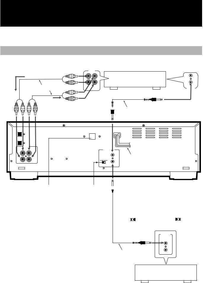
Analog Connections
Use the accessory pin cables to connect this unit’s LINE connectors with the TAPE/CDR connectors on the receiver, etc.
Recording signals |
TAPE |
|
(line input) |
/CDR |
|
|
|
|
|
|
Amplifier, receiver etc. |
|
|
made by JVC |
Accessory pin cables |
OUT IN |
COMPU LINK-4 |
(REC) (PLAY) |
SYNCHRO |
Playback signals
 Accessory connecting cable
(with black plugs)
XL-R5000 CD/CDR MULTIPLE
COMPACT DISC RECORDER
DIGITAL IN |
|
OPTICAL |
VOLTAGE SELECTOR |
|
DIGITAL OUT
OPTICAL
LINE
IN ( REC) OUT (PLAY ) COMPU LINK-4 (SYNCHRO)
LEFT |
LEFT |
|
|
|
MODE |
RIGHT |
RIGHT |
CDR TD |
Units have a voltage selector excluding units for |
MODE switch |
|
|
|
|
|
|||
Canada, Europe, and U.S.A. |
|
|
|
|
|
|
|
|
|
|
|
|
|
|
|
|
|
|
|
|
|
|
|
|
|
|
|
|
|
|
|
|
|
|
|
|
|
|
|
Power cord
Selecting the MODE switch position
• When connected with |
• When connected with |
CDR input/output |
TAPE input/output |
terminals of the amplifier |
terminals of the amplifier |
or receiver |
or receiver |
Note
•Before selecting the COMPU LINK-4 mode (CDR or TD), disconnect the power cord from the power outlet to turn off the power. The function will not be set if it is selected while the power is on.
Alternatively, when the COMPU LINK-4 mode (CDR or TD) is selected while the power is on, disconnect the power cord and then re-connect it.
•Misconnections can be avoided by using the white plugs on the accessory pin cables for the LEFT channel and the red plugs for the RIGHT channel.
•Insert the plugs all the way in. Incomplete connections may cause noise.
•When plugging the power cord into the AC outlet, be sure to match the width of the plug blades with the outlet.
MODE |
|
MODE |
|||||||
CDR TD |
|
CDR TD |
|||||||
|
|
|
|
|
|
|
|
|
|
|
|
|
|
|
|
|
|
|
|
|
|
|
|
|
|
|
|
|
|
•For further details on the COMPU LINK function, see page 37.
COMPU LINK-3
SYNCHRO
Optional connecting cable
CD player, cassette deck or other component made by JVC
3
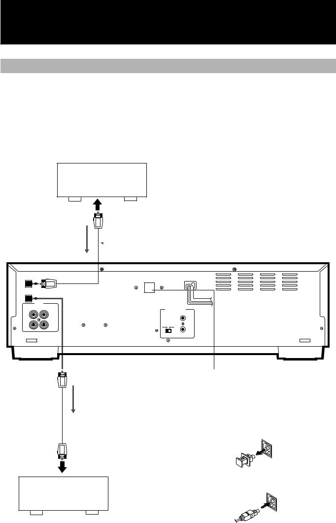
Digital Connections
Before proceeding, check whether the optical digital cable can be connected.
•Connect a receiver or amplifier with digital audio capability to the DIGITAL OPTICAL connectors on this unit.
•One connecting cable is used to transmit the stereo signals (L/
R)as a digital signal.
•If analog audio connections are also being made, try to use the digital connectors on the receiver or amplifier that are labeled the same way as the analog connectors.
•Before purchasing an optical digital cable (optional), make sure that the cable in question can be connected to the amplifier, etc.
•Do not bend the optical digital cable at a sharp angle.
•When the power is turned on, the inside of the connector lights up red. This light is for sending the digital signals. Although this light will not harm your eyes, keep the protective cap in place if the connector is not going to be used.
DIGITAL IN |
|
OPTICAL |
|
DIGITAL OUT |
|
OPTICAL |
|
LINE |
|
IN ( REC) OUT (PLAY ) |
|
LEFT |
LEFT |
RIGHT |
RIGHT |
To DIGITAL |
|
OUT OPTICAL |
|
connector |
|
Input signal
CD player, etc.
To OPTICAL OUTPUT connector
 Optional optical digital cable
XL-R5000 CD/CDR MULTIPLE
COMPACT DISC RECORDER
VOLTAGE SELECTOR
COMPU |
LINK-4 |
|
|
(SYNCHRO) |
|
MODE |
|
|
CDR |
TD |
|
Units have a voltage selector excluding units for
Canada, Europe, and U.S.A.
Output signal
 Optional optical digital cable
How to use the OPTICAL connectors for the connections
1 Remove the protective cap.
•When the connector is not going to be used, fit this protective cap back in position.
To OPTICAL INPUT connector
2 Check that the end of the optical digital cable is
not dirty, and insert it securely.
Receiver or amplifier with digital OPTICAL connector
4

Names of the Parts
Main Unit |
|
|
|
|
|
|
|
|
|
|
|
|
|
|
|
|
XL - R5000 |
CD/CDR MULTIPLE COMPACT DISC RECORDER |
|
|
|
|
|
|
REC LEVEL |
|
|||||
|
|
|
|
|
|
|
|
|
|
|
|
EJECT |
|
|
|
|
|
|
|
|
|
3-CD |
|
REC SOURCE SELECTOR |
|
|
|
|
|
|
|
|
|
|
|
|
|
DIGITAL |
CD |
LINE |
MIC |
FINALIZE |
|
|
|
|
|
|
|
|
|
|
|
PLAY & EXCHANGE |
|
|
|
|
|||||
|
|
|
|
|
|
|
|
|
|
|
|
|
MIN |
MAX |
|
|
|
|
|
|
|
|
|
|
MIXING |
|
|
|
|
|
|
|
CLOCK/ |
PLAY |
CD CONTROL |
|
|
|
|
|
CDR CONTROL |
MIX BALANCE |
PHONES LEVEL |
||||
|
CD EDIT |
CD REC |
|
|
|
|
REC |
SYNCHRO |
REC |
|
|
|
|||
|
TIMER |
MODE |
MENU |
|
|
MULTI JOG |
MUTING |
|
|
|
|||||
|
|
|
|
|
DISPLAY |
|
|
|
|
|
|
|
|
||
STANDBY |
STANDBY |
|
|
|
|
|
|
|
|
|
|
|
|
|
|
|
|
|
|
|
|
|
|
|
– |
+ |
|
LINE |
CD |
MIN |
MAX |
|
|
|
|
|
|
|
|
|
|
MIC |
LINE |
|
|
||
|
POWER |
|
|
|
CANCEL |
SET |
|
|
|
|
MIC |
PHONES |
|||
|
|
|
|
|
|
|
|
|
|
|
|
|
|
|
|
STANDBY/ON |
|
|
|
|
|
|
|
|
|
|
|
|
|
|
|
 POWER button and STANDBY lamp (for Canada and U.S.A)
 button and STANDBY lamp (for other countries)
Press to turn the power on or to put in standby. When the unit is in standby, the STANDBY lamp is lit. (See page 10.)
 CD trays 1, 2, and 3 (numbered from bottom to top)
Load CDs on these trays for 3-CD changer playback. (See page 11.)
 Disc tray selector buttons (with current selection lamp) and 0(eject) buttons
Press to select one of the CDs loaded in the 3-CD changer. The lamp on the button lights to indicate the currently selected tray. Use the 0 (eject) buttons to open and close the corresponding disc trays. (See page 11.)
 CDR disc tray
Load a recordable CD-R or CD-RW in this tray for recording. CD playback is also available using this tray.
 FINALIZE button
Press to finalize a CD-R or CD-RW disc when recording on the disc has been completed. (See page 29.)
 EJECT 0
Press to open and close the CDR disc tray.
 REC LEVEL control and lamp
Use to adjust the level of the source signal being recorded. (See page 18 and 25.)
 PHONES LEVEL control
Use to adjust the level of the volume being output to connected headphones (not supplied).
 PHONES connector
Use to connect headphones (not supplied) to this unit.
 MIX BALANCE control and lamp
Use to control the mixing levels of two independent sources being recorded. The lamp is lit during mixed recording. (See page 26.)
 MIC connector
Use to connect a microphone (not supplied) to this unit. (See page 18.)
 CDR CONTROL operation buttons
REC MUTING: Press to record silence during a recording. (See
|
page 19.) |
SYNCHRO: |
Press to select synchronized start recording. (See |
|
page 25.) |
REC ¦: |
Press to put this unit in record pause mode for |
|
manual recording. (See page 18 and 26.) |
7(stop): |
Press to stop recording or play of the CDR. (See |
|
page 12 and 19.) |
8(pause): |
Press to pause play and recording. (See page 12.) |
3(play): |
Press to start play or recording (in record pause |
|
mode) of the CDR. (See page 12 and 19.) |
 MULTI JOG dial
Depending on the mode, use to skip forward or backward through tracks on a CD, change the clock settings, or select setting options. (See pages 14, 16, 23, and 33.)
 REC SOURCE SELECTOR buttons
Use to select the type of source to be recorded. (See pages 18 and 26.)
 Display window
Displays the operation modes and other system information. (See page 7.)
 MENU button
Press to enter a menu option.
 SET button
Press to enter a selection.
 CANCEL button
Press to cancel an operation.
 DISPLAY button
Press repeatedly to change the type of information that appears in the display window information display.
5
CD CONTROL operation buttons
PLAY MODE: Press repeatedly to select one of the play modes for
|
the 3-CD changer. (See page 15 and 16.) |
CD EDIT: |
Press to select either the Listening Edit or Program |
|
Edit recording modes. (See page 21 and 22.) |
CD REC: |
Press to perform synchronized recording of the |
|
currently selected CD in the 3-CD changer. (See |
|
page 20 and 21.) |
7(stop): |
Press to stop play of the selected disc in the 3-CD |
|
changer. (See page 11.) |
8(pause): |
Press to pause play of the selected disc in the 3-CD |
|
changer. (See page 11.) |
3(play): |
Press to start play of the selected disc in the 3-CD |
|
changer. (See page 11.) |
Remote control sensor
Receives commands from the remote control.
CLOCK/TIMER button
Use to set the time. (See page 33.)
6

Display Window
PROGRAM |
|
|
|
|
|
|
|
|
|
|
|
RANDOM |
|
|
|
|
|
|
|
|
|
|
|
REPEAT |
|
|
|
|
|
|
|
|
|
|
|
ALL 1CD |
|
|
|
|
|
|
|
|
|
|
|
CD PLAYER |
1 |
2 |
3 |
4 |
5 |
SKIP ON ANALOG |
CD RECORDER SYNCHRO |
||||
LISTENING EDIT |
6 |
7 |
8 |
9 |
10 |
DAILY |
DIGITAL |
REC |
HIGH SPEED AUTO TRACK |
||
PROGRAM EDIT |
11 12 13 14 15 |
|
32kHz |
CD CD-R |
|
OVER |
|||||
CD REC 1CD |
ONCE |
L |
|||||||||
16 |
17 |
18 |
19 |
20 |
44.1kHz |
CD–RW |
40 30 20 15 10 6 3 0 dB |
||||
– PITCH + |
|
48kHz |
FINALIZED |
– |
|||||||
|
|
|
|
|
|
|
R |
|
|||
 CD numbers and play status displays
Indicate whether discs are loaded in any of the 3-CD changer disc trays, which disc is currently selected, and the operation status of the current disc. (See page 12.)
 PLAY MODE indicators
Light according to which play mode has been selected. (See page 14 to 16.)
 CD PLAYER indicator
Lights when the 3-CD changer is selected for play.
 Information display
Displays track, time, and operation information.
 SKIP ON indicator
Lights when the currently selected disc contains SKIP TRACK markers.
 CD RECORDER indicator
Lights when the CDR has been selected for play or recording.
 HIGH SPEED indicator
Lights when the high speed (2x) dubbing function is being performed. (See page 23.)
 Synchronized recording indicators
Light to indicate synchronized recording is on. (See page 20.)
 AUTO TRACK indicator
Lights when automatic track marking has been turned on. (See page 18.)
 Level meter
Indicates the level of the right and left channels during playback and recording operations. When the input signal exceeds 0 dB, the OVER indicator lights. (See page 18.)
 Disc format indicators
Light to indicate the type of disc that is loaded in the CDR.
 CDR deck operation indicators
Light to indicate the operation mode of the CDR.
 Recording type indicators and sampling frequency indicators
Light to indicate whether the recording is analog or digital. During digital recording, the appropriate frequency indicator lights to indicate the sampling frequency of the source being recorded. (See page 18.)
 Timer operation indicators
Indicate that a Timer Play or Timer Recording function has been set, and whether it is set for everyday or one-time operation. (See pages 33.)
 Music calendar
Indicates the number of tracks on the currently selected CD or CDR, and the track on the disc that is being played or recorded.
 EDIT recording indicators
Indicates whether the Listening Edit or Program Edit functions are being performed. (See pages 21 and 22.)
 1CD indicator
Lights during synchronized recording. (See page 20.)
 PITCH (+/–) indicators
Indicate that the pitch of CD play has been adjusted in one direction or the other. (See page 15.)
 3-CD changer operation indicators
Light to indicate the operation mode of the 3-CD changer.
 CD REC indicator
Indicates the CD(s) loaded in the 3-CD changer is being recorded by the CDR.
7

Remote Control
CD REC |
SYNCHRO |
DISPLAY POWER |
CD EDIT |
FINALIZE |
MENU |
CD 1
1 2 3
CD 2
4 5 6
CD 3
7 8 9
CONTROL
10 +10 CD CDR
PLAY MODE REPEAT SET |
CANCEL |
PITCH +
|
PITCH 0 |
|
REC |
SHIFT |
PITCH – |
REC MUTING |
|
|
REMOTE CONTROL |
|
RM-SXLR5000J |
When performing the procedures in this manual, the buttons on the remote control have the same function as the corresponding buttons on the main unit.
 SYNCHRO/FINALIZE button
Press to select synchronized start recording. (See page 25.)
When SHIFT is pressed down, press to start finalization of a CD-R or CD-RW. (See page 29.)
 CD REC/CD EDIT button
Press to start the CD REC function. (See pages 21.)
When SHIFT is pressed down, press repeatedly to select Listening Edit or Program Edit functions. (See pages 21 and 22.)
 Number buttons
Press to select a track for playback. (See page 13.)
 PLAY MODE button
Press repeatedly to select a play mode for the 3-CD changer. (See page 15.)
 REPEAT button
Press repeatedly to select one of the repeat play modes. (See page 14.)
 1(reverse) button
Press to perform fast reverse search of the currently selected CD. (See page 13.)
 3 (play)/PITCH + button
Press to play the currently selected CD. (See page 10 and 12.) When SHIFT is pressed down, press to raise the pitch of CD playback. (See page 15.)
 4(skip reverse) button
Press to skip back to the beginning of previous tracks. (See page 14.)
 SHIFT button
Press down in conjunction with other buttons on the remote control to make use of their secondary functions.
 DISPLAY/MENU button
Press repeatedly to change the type of information that appears in the display window information display.
When SHIFT is pressed down, press to enter a menu option.
 POWER (for Canada and U.S.A.)/
  (for other countries) button
Press to turn the power of this unit on or to put in standby. (See page 10.)
 CD1, CD2, and CD3 disc selection buttons
Use to select one of the discs loaded in the 3-CD changer. (See page 10,12, and 13.)
 CD and CDR deck selection buttons
Press to change the function of this unit to the 3-CD changer or CDR. (See page 12.)
 CANCEL button
Press to cancel an operation.
 SET button
Press to enter a selection.
 Á (forward) button
Press to perform fast forward search of the currently selected CD. (See page 13.)
 8 (pause)/ PITCH 0 button
Press to pause playback of the currently selected disc. (See page 12.)
When SHIFT is pressed down, press to restore the pitch level of CD playback. (See page 15.)
 ¢(skip forward) button
Press to skip forward to other tracks on the disc. (See page 14.)
 REC ¦/REC MUTING button
Press to put this unit in the record pause mode. (See page 18 and 26.)
When SHIFT is pressed down, press to record silence during a recording. (See page 19.)
 7 (stop)/PITCH - button
Press to stop playback of the currently selected disc. (See page 12.) When SHIFT is pressed down, press to lower the pitch level of CD playback. (See page 15.)
8
Using the Remote Control
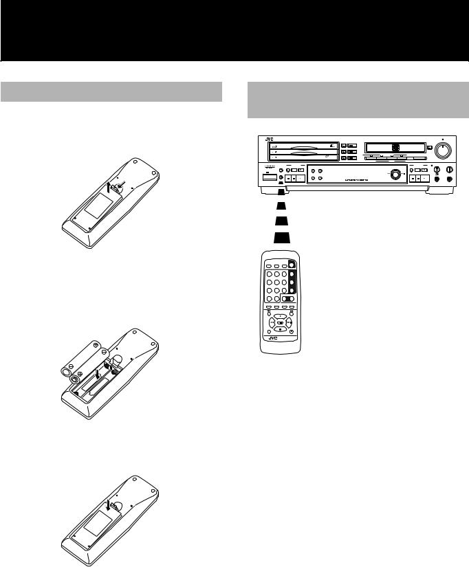
Installing the batteries
1 Press down on the point shown by the arrow at
the top of the compartment cover, and pull up the cover to open the compartment.
2 Place the two accessory AA (15F), R6, SUM-3 batteries in the remote control making sure to align the polarity markings (“+” and “–”) inside the compartment and on the batteries.
3 Place the cover over the compartment, and press down lightly.
How to use the remote control correctly
XL - R5000 CD/CDR MULTIPLE COMPACT DISC RECORDER |
|
|
|
|
|
|
REC LEVEL |
||||
|
|
|
|
|
|
|
|
|
EJECT |
|
|
|
|
|
3-CD |
|
REC SOURCE SELECTOR |
|
|
|
|
|
|
|
|
|
DIGITAL |
CD |
LINE |
MIC |
FINALIZE |
|
|
|
|
|
|
|
PLAY & EXCHANGE |
|
|
|
|||||
|
|
|
|
|
|
|
|
|
|
MIN |
MAX |
|
|
|
|
|
|
MIXING |
|
|
|
|
|
|
CD CONTROL |
|
|
|
|
|
|
CDR CONTROL |
MIX BALANCE |
PHONES LEVEL |
|
CLOCK/ |
PLAY |
|
|
|
|
|
|
REC |
|
|
|
TIMER |
MODE CD EDIT CD REC |
DISPLAY |
MENU |
|
|
MULTI JOG |
|
MUTING SYNCHRO |
REC |
|
|
STANDBY |
|
|
|
|
|
|
|
|
|
|
|
|
|
|
|
|
|
– |
+ |
|
LINE |
CD |
MIN MAX |
|
|
CANCEL |
SET |
|
|
|
MIC |
LINE |
|
||
|
|
|
|
|
|
MIC |
PHONES |
||||
POWER
CD REC |
SYNCHRO |
DISPLAY POWER |
CD EDIT |
FINALIZE |
MENU |
|
|
|
CD 1 |
1 |
2 |
3 |
|
|
|
|
CD 2 |
4 |
5 |
6 |
|
|
|
|
CD 3 |
7 |
8 |
9 |
|
|
|
CONTROL |
|
10 |
+10 |
CD |
CDR |
PLAY MODE |
REPEAT |
SET |
CANCEL |
|
PITCH + |
|
|
|
PITCH 0 |
|
|
|
|
|
REC |
SHIFT |
PITCH – |
REC MUTING |
|
REMOTE CONTROL
RM-SXLR5000J
•Point the remote control correctly at the remote control sensor on the main unit when pressing the buttons.
•The remote control can be operated at a distance of up to 7 meters or so from the remote control sensor. This distance will be less if the remote control is operated from a position which is not directly in front or on the same level as the main unit.
•When the distance over which the remote control can be operated starts to drop, it means that the batteries are nearing the end of their service life.
•Replace both batteries (AA (15F), R6, SUM-3) with fresh units.
•The dry batteries provided with the unit are for operational check purposes. Replace them with fresh units at the earliest opportunity.
•Do not drop the remote control or subject it to strong impact.
•In order to ensure that the remote control does not fail to operate, avoid operation under the following conditions:
•When the remote control sensor is exposed to direct sunlight or other intense sources of light
•When objects in front of the remote control sensor block the transmission of signals from the remote control
9

Power ON/STANDBY Operations
Turning the power on and putting in standby
0 CD1, CD2, CD3 |
0 |
|
XL - R5000 CD/CDR MULTIPLE COMPACT DISC RECORDER |
REC LEVEL |
|
|
MIN |
MAX |
|
MIX BALANCE |
PHONES LEVEL |
MULTI JOG |
|
|
|
STANDBY |
|
|
|
POWER |
– |
+ |
POWER |
3 |
3 |
|
( |
) |
|
|
CD REC SYNCHRO DISPLAY POWER |
|
CD EDIT FINALIZE MENU |
) |
POWER ( |
CD 1
1 |
2 |
3 |
|
|
|
|
CD 2 |
4 |
5 |
6 |
CD1, CD2, CD3 |
|
|
|
CD 3 |
7 |
8 |
9 |
|
|
|
CONTROL |
|
10 |
+10 |
CD |
CDR |
PLAY MODE REPEAT |
SET |
CANCEL |
|
|
PITCH + |
3 |
|
|
|
|
|
|
PITCH 0 |
|
|
|
|
|
REC |
SHIFT |
PITCH – |
REC MUTING |
|
|
|
||
REMOTE CONTROL
RM-SXLR5000J
To turn on the power
Press the POWER (for Canada and U.S.A.)/ (for other countries) button on the front panel or remote control.
Main Unit Remote Control |
Main Unit Remote Control |
Lamp goes out. |
Lamp goes out. |
POWER |
|
STANDBY |
STANDBY |
POWER |
|
|
STANDBY/ON |
For Canada and U.S.A. |
For other countries. |
• The currently selected function appears in the display window.
To put the power to standby
Press the POWER (for Canada and U.S.A.)/ (for other countries) button on the front panel or remote control.
Main Unit Remote Control |
Main Unit Remote Control |
Lamp lights |
Lamp lights |
POWER |
|
|
STANDBY |
STANDBY |
|
POWER |
|
|
STANDBY/ON |
For Canada and U.S.A. |
For other countries. |
•The clock display appears in the display window. It flashes if the clock has not been set.
•The power can only be put to standby by pressing the POWER
(for Canada and U.S.A.)/ |
|
(for other countries) button press- |
ing. |
|
|
If the POWER (for Canada and U.S.A.)/ (for other countries) button is pressed during recording, the standby lamp flashes while the unit brings the operation to a stop. Once the unit has been put in the stop mode, the unit is put in standby and the standby lamp lights steady. During this time, there is no effect if any of the buttons on the front panel or remote control (including POWER (for Canada and U.S.A.)/
 (for other countries)) are pressed.
To turn on the power by pressing a function button
When the power is switched to STANDBY, it can be turned on and a function selected simply by pressing one of the buttons shown in the figure below
|
|
|
Function |
Operation |
|
|
|
|
|
Main unit |
|
|
||
|
|
|
|
The function is set to CD. The |
|
|
|
|
CD PLAYER indiator lights. |
|
|
|
|
If one of these buttons is |
|
|
|
|
pressed when a CD is on the |
Remote control |
|
corresponding CD tray, con- |
||
CD |
tinuous play starts from the |
|||
|
CD 1 |
|
CD tray which corresponds to |
|
|
|
|
|
the button pressed. |
|
CD 2 |
|
These buttons do not function |
|
|
|
|
|
during program and random |
|
CD 3 |
|
play modes. |
|
|
|
|
||
|
|
|
|
|
Main unit |
|
|
||
(CD control) |
CD |
The function is set to CD. The |
||
|
|
|
CD PLAYER indicator lights. |
|
|
|
|
|
|
|
|
|
|
|
|
|
|
|
|
Main unit |
|
The function is set to CDR. |
||
(CDR control) |
|
|||
|
|
|
CDR |
The CD RECORDER indica- |
|
|
|
||
|
|
|
|
tor lights. |
|
|
|
|
|
|
|
|
|
|
•When the 3 button for either the 3-CD changer or CDR is pressed, the power is turned on and the corresponding tray is selected. If a disc is loaded in the selected tray, playback begins. If the power has been turned on, pressing 3on the remote control selects the last selected function (3-CD changer or CDR) and starts playback of the disc loaded in the selected tray.
•When one of the 3-CD changer 0 (eject) buttons or the CDR EJECT 0button is pressed, the power is turned on and the tray opens, but the currently selected function (3-CD changer or CDR) does not change.
•If the main power is turned off or if the AC power cord is unplugged from the wall outlet for longer than an hour, the internal clock, program etc. of this unit may be reset. When this occurs, please set the clock (and timer functions) again.
10
Loading...