


AV-1406FE
jvc AV-1406FE, AV-14146-N, AV-14149-N, AV-14F16, AV-14FMG6-G Service Manual
...
SERVICE MANUAL
COLOUR TELEVISION
YA37020062
AV-1406FE, AV-14146/N,
AV-14149
/N, AV-14F16,
AV-14FMG6
/G, AV-14FMG6/S
BASIC CHASSIS
CG4
TABLE OF CONTENTS
1 PRECAUTION. . . . . . . . . . . . . . . . . . . . . . . . . . . . . . . . . . . . . . . . . . . . . . . . . . . . . . . . . . . . . . . . . . . . . . . . . 1-3
2 SPECIFIC SERVICE INSTRUCTIONS . . . . . . . . . . . . . . . . . . . . . . . . . . . . . . . . . . . . . . . . . . . . . . . . . . . . . . 1-4
3 DISASSEMBLY . . . . . . . . . . . . . . . . . . . . . . . . . . . . . . . . . . . . . . . . . . . . . . . . . . . . . . . . . . . . . . . . . . . . . . . 1-5
4 ADJUSTMENT . . . . . . . . . . . . . . . . . . . . . . . . . . . . . . . . . . . . . . . . . . . . . . . . . . . . . . . . . . . . . . . . . . . . . . . 1-11
5 TROUBLESHOOTING . . . . . . . . . . . . . . . . . . . . . . . . . . . . . . . . . . . . . . . . . . . . . . . . . . . . . . . . . . . . . . . . . 1-24
COPYRIGHT © 2006 Victor Company of Japan, Limited
No.YA370
2006/2
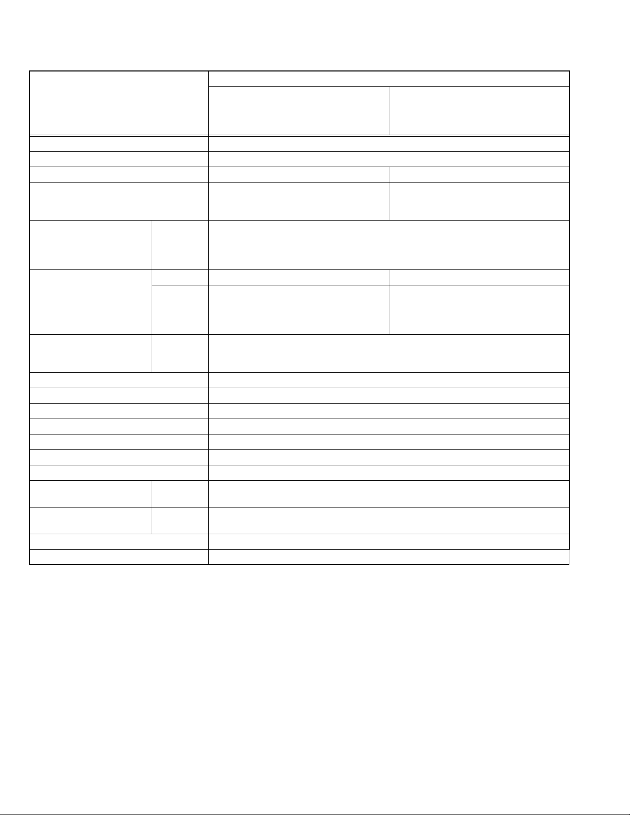
SPECIFICATION
Contents
Items
Dimensions (W × H × D) 46.2 cm × 34.1 cm × 37.5 cm
Mass 10 kg
TV RF System B/G, I, D/K B/G, I, D/K, M
Colour System PAL
SECAM
NTSC 3.58 / NTSC 4.43 (NTSC:EXT only).
Receiving
Frequency
Intermediate Frequency VIF 38.0 MHz (B/G, I, D/K) 38.0 MHz (B/G, I, D/K, M)
Colour Sub Carrier PAL
Power Input AC110 V to AC240 V, 50 Hz / 60Hz
Power Consumption 68 W (Max) / 47W(Avg)
Picture Tube Visible size: 34 cm measured diagonally ( H : 28.7 cm × V : 21.7 cm)
High Voltage 22.5 kV±1.5kV (at zero beam current)
Speaker 5 cm × 9 cm, Oval type × 2
Audio Power Output 3 W (monaural)
Aerial Input Terminal 75 Ω unbalanced, coaxial
Input Terminal
[Front / Rear]
Output Terminal
[Rear]
Headphone Jack 3.5 mm mini jack × 1
Remote Control Unit RM-C360GY (Battery size : AA / R6 / UM-3 × 2)
VHF Low
VHF High
SECAM
46.25 MHz to 140.25 MHz
147.25 MHz to 423.25 MHz
UHF
431.25 MHz to 863.25 MHz
CATV
Mid (X to Z+2, S1 to S10) / Super (S11 to S20) / Hyper (S21 to S41) bands
SIF 32.5 MHz (5.5 MHz: B/G)
32MHz (6.0 MHz: I)
31.5MHz (6.5 MHz: D/K)
4.43 MHz
4.40625 MHz / 4.25 MHz
NTSC
3.58 MHz / 4.43 MHz
Video
1 V(p-p), 75 Ω, RCA pin jack × 2
Audio
500 mV(rms) (-4 dBs), High impedance, RCA pin jack × 2
Video
1 V(p-p), 75Ω, RCA pin jack × 1
Audio
500 mV(rms) (-4 dBs), Low impedance, RCA pin jack × 1
AV-1406FE
AV-14146/N
AV-14149/N
AV-14F16
AV-14FMG6/G
AV-14FMG6/S
PAL
SECAM
NTSC 3.58 / NTSC 4.43
32.5 MHz (5.5 MHz: B/G)
32MHz (6.0 MHz: I)
31.5MHz (6.5 MHz: D/K)
33.5MHz (4.5 MHz: M)
Design and specifications are subject to change without notice.
1-2 (No.YA370)

SECTION 1
PRECAUTION
1.1 SAFETY PRECAUTIONS
(1) The design of this product contains special hardware,
many circuits and components specially for safety
purposes. For continued protection, no changes should be
made to the original design unless authorized in writing by
the manufacturer. Replacement parts must be identical to
those used in the original circuits. Service should be
performed by qualified personnel only.
(2) Alterations of the design or circuitry of the products should
not be made. Any design alterations or additions will void
the manufacturer's warranty and will further relieve the
manufacturer of responsibility for personal injury or
property damage resulting therefrom.
(3) Many electrical and mechanical parts in the products have
special safety-related characteristics. These
characteristics are often not evident from visual inspection
nor can the protection afforded by them necessarily be
obtained by using replacement components rated for
higher voltage, wattage, etc. Replacement parts which
have these special safety characteristics are identified in
the parts list of Service manual. Electrical components
having such features are identified by shading on the
schematics and by ( ) on the parts list in Service
manual. The use of a substitute replacement which does
not have the same safety characteristics as the
recommended replacement part shown in the parts list of
Service manual may cause shock, fire, or other hazards.
(4) Don't short between the LIVE side ground and
ISOLATED (NEUTRAL) side ground or EARTH side
ground when repairing.
Some model's power circuit is partly different in the GND.
The difference of the GND is shown by the LIVE : ( ) side
GND, the ISOLATED (NEUTRAL) : ( ) side GND and
EARTH : ( ) side GND.
Don't short between the LIVE side GND and ISOLATED
(NEUTRAL) side GND or EARTH side GND and never
measure the LIVE side GND and ISOLATED (NEUTRAL)
side GND or EARTH side GND at the same time with a
measuring apparatus (oscilloscope etc.). If above note will
not be kept, a fuse or any parts will be broken.
(5) If any repair has been made to the chassis, it is
recommended that the B1 setting should be checked or
adjusted (See ADJUSTMENT OF B1 POWER SUPPLY).
(6) The high voltage applied to the picture tube must conform
with that specified in Service manual. Excessive high
voltage can cause an increase in X-Ray emission, arcing
and possible component damage, therefore operation
under excessive high voltage conditions should be kept to
a minimum, or should be prevented. If severe arcing
occurs, remove the AC power immediately and determine
the cause by visual inspection (incorrect installation,
cracked or melted high voltage harness, poor soldering,
etc.). To maintain the proper minimum level of soft X-Ray
emission, components in the high voltage circuitry
including the picture tube must be the exact replacements
or alternatives approved by the manufacturer of the
complete product.
(7) Do not check high voltage by drawing an arc. Use a high
voltage meter or a high voltage probe with a VTVM.
Discharge the picture tube before attempting meter
connection, by connecting a clip lead to the ground frame
and connecting the other end of the lead through a 10kΩ
2W resistor to the anode button.
(8) When service is required, observe the original lead dress.
Extra precaution should be given to assure correct lead
dress in the high voltage circuit area. Where a short circuit
has occurred, those components that indicate evidence of
overheating should be replaced. Always use the
manufacturer's replacement components.
(9) Isolation Check (Safety for Electrical Shock Hazard)
After re-assembling the product, always perform an
isolation check on the exposed metal parts of the cabinet
(antenna terminals, video/audio input and output terminals,
Control knobs, metal cabinet, screw heads, earphone jack,
control shafts, etc.) to be sure the product is safe to operate
without danger of electrical shock.
a) Dielectric Strength Test
The isolation between the AC primary circuit and all metal
parts exposed to the user, particularly any exposed metal
part having a return path to the chassis should withstand a
voltage of 3000V AC (r.m.s.) for a period of one second. (.
. . . Withstand a voltage of 1100V AC (r.m.s.) to an
appliance rated up to 120V, and 3000V AC (r.m.s.) to an
appliance rated 200V or more, for a period of one second.)
This method of test requires a test equipment not generally
found in the service trade.
b) Leakage Current Check
Plug the AC line cord directly into the AC outlet (do not use
a line isolation transformer during this check.). Using a
"Leakage Current Tester", measure the leakage current
from each exposed metal part of the cabinet, particularly
any exposed metal part having a return path to the chassis,
to a known good earth ground (water pipe, etc.). Any
leakage current must not exceed 0.5mA AC (r.m.s.).
However, in tropical area, this must not exceed 0.2mA AC
(r.m.s.).
Alternate Check Method
Plug the AC line cord directly into the AC outlet (do not
use a line isolation transformer during this check.). Use
an AC voltmeter having 1000Ω per volt or more
sensitivity in the following manner. Connect a 1500Ω
10W resistor paralleled by a 0.15µF AC-type capacitor
between an exposed metal part and a known good earth
ground (water pipe, etc.). Measure the AC voltage
across the resistor with the AC voltmeter. Move the
resistor connection to each exposed metal part,
particularly any exposed metal part having a return path
to the chassis, and measure the AC voltage across the
resistor. Now, reverse the plug in the AC outlet and
repeat each measurement. Any voltage measured must
not exceed 0.75V AC (r.m.s.). This corresponds to
0.5mA AC (r.m.s.).
However, in tropical area, this must not exceed 0.3V AC
(r.m.s.). This corresponds to 0.2mA AC (r.m.s.).
AC VOLTMETER
(HAVING 1000 /V,
OR MORE SENSITIVITY)
0.15 F AC-TYPE
PLACE THIS PROBE
1500 10W
GOOD EARTH GROUND
ON EACH EXPOSED
ME TAL PAR T
(No.YA370)1-3
SECTION 2
SPECIFIC SERVICE INSTRUCTIONS
2.1 FEATURES
PICTURE MODE
This function can adjust the picture settings automatically.
There are BRIGHT, STANDARD and SOFT in the PICTURE
MODE.
RETURN +
This function can set a channel you frequently view to the
Return Channel and you can view that channel at any time with
one-touch.
2.2 MAIN DIFFERENCE LIST
Item AV-1406FE AV-14146/N AV-14149/N AV-14F16 AV-14FMG6/G AV-14FMG6/S
RF System PAL, SECAM ←←←
Broadcasting System B/G, I, D/K ←←←B/G, I, D/K, M ←
OSD Language Eng, Rus, Ukr Eng ← Eng, Chi, Rus
Plug Type EU Type (2 Pins) ←←←←UK Type (3 Pins)
MAIN PWB SCG-1326A-H2 SCG-1327A-H2 SCG-1328A-H2 SCG-1323A-H2 SCG-1324A-H2 SCG-1325A-H2
CHILD LOCK
Use this function to prevent children from operating the TV
without parental consent.
VNR
This function can reduce the picture noise.
PAL, SECAM,
NTSC3.58/4.43
Eng, Ara, Per, Rus
←
←
2.3 TECHNINAL INFORMATION
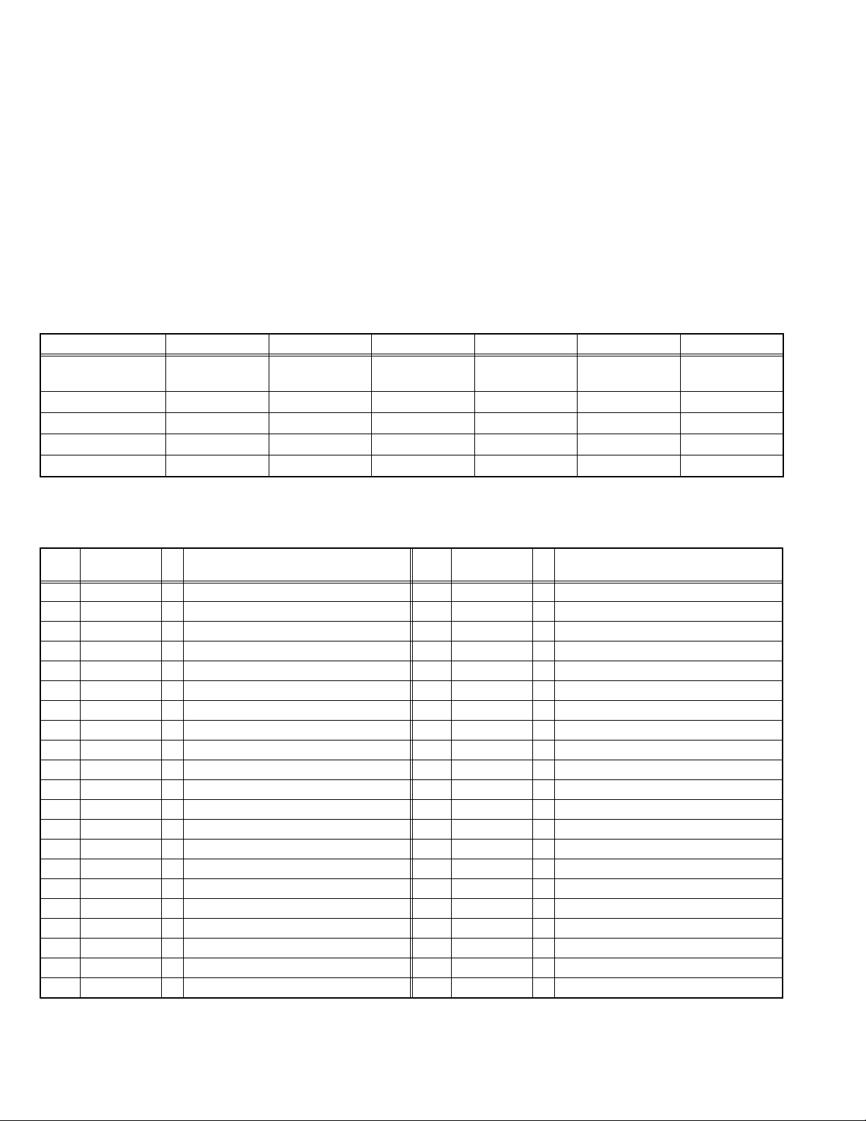
2.3.1 MAIN MI-COM (CPU) PIN FUNCTION
Pin
No.
Pin name I/O Function
1 REMOCON I Remote control 22 PROTECT I Low B protect detection [Detect: H]
2 SDA2 I/O Data for Inter IC control (For main memory) 23 P_ON/OFF I Main power control [ON : H]
3 SCL2 O Clock for Inter IC contorl (For main memory) 24 LOCK - Not used
4 BUS_FREE - Not used 25 3.58/OTH - Not used
5 NC - Not used 26 4.5/OTH - Not used
6 KEY1 I Key scan for front key (Menu CH -/+) 27 H_SYNC I Horizontal sync
7 KEY2 I Key scan for front key (Vol -/+) 28 I/II - Not used
8 ECO IN - Not used 29 OSD_Ys O Ys (blanking) for OSD
9 AFT I AFT voltage for tuner 30 OSD_B O Blue for OSD
10 LED[POW] - Not used 31 OSD_G O Green for OSD
11 LED[TIM] O Liting for timer [Liting : H] 32 OSD_R O Red for OSD
12 GND - GND 33 NC - Not used
13 NC - Not used 34 RST I CPU reset [Reset:L]
14 NC - Not used 35 V_SYNC I Vertical sync
15 TV/V - Not used 36 TCLOCK - Not used
16 TEXT RESET - Not used 37 SDA1 I/O Data for Inter IC control (For generally)
17 ACL ON/OFF - Not used 38 SCL1 O Clock for Inter IC contorl (For generally)
18 VOL O Volume control 39 VDD I 3.3V
19 A_MUTE O Aodio muting [Muting : H] 40 OSC1 I System clock oscillation (4MHz)
20 NC - Not used 41 OSC2 O System clock oscillation (4MHz)
21 TEXT/OTH - Not used 42 VSS - GND
Pin
No.
Pin name I/O Function
1-4 (No.YA370)

SECTION 3
DISASSEMBLY
3.1 DISASSEMBLY PROCEDURE
3.1.1 REMOVING THE REAR COVER
(1) Unplug the power cord.
(2) Remove the 5 screws [A] and 1 screw [B].
(3) Withdraw the REAR COVER toward you.
3.1.2 REMOVING THE MAIN PW BOARD
• Remove the REAR COVER.
(1) Slightly raise the both sides of the MAIN PW BOARD by
hand and remove the PWB STOPPER under the MAIN PW
BOARD from the FRONT CABINET.
(2) Withdraw the MAIN PW BOARD backward.
(If necessary, take off the wire clamp, connectors etc.)
3.1.3 REMOVING THE SPEAKER
• Remove the REAR COVER.
(1) Remove the 2 or 4 screws [C].
(2) Remove the SPEAKER.
(3) Follow the same steps when removing the other hand
SPEAKER.
3.1.4 CHECKING THE MAIN PW BOARD
• To check the back side of the PW BOARD.
(1) Pull out the MAIN PW BOARD. (Refer to REMOVING THE
MAIN PW BOARD)
(2) Erect the PW BOARD vertically so that you can easily
check the back side of the PW BOARD.
CAUTION:
• When erecting the PW BOARD, be careful so that there will
be no contacting with other PW BOARD.
• Before turning on power, make sure that the CRT earth wire
and other connector are properly connected.
3.1.5 WIRE CLAMPING AND CABLE TYING
(1) Be sure to clamp the wire.
(2) Never remove the cable tie used for tying the wires
together.
Should it be inadvertently removed, be sure to tie the wires
with a new cable tie.
(No.YA370)1-5
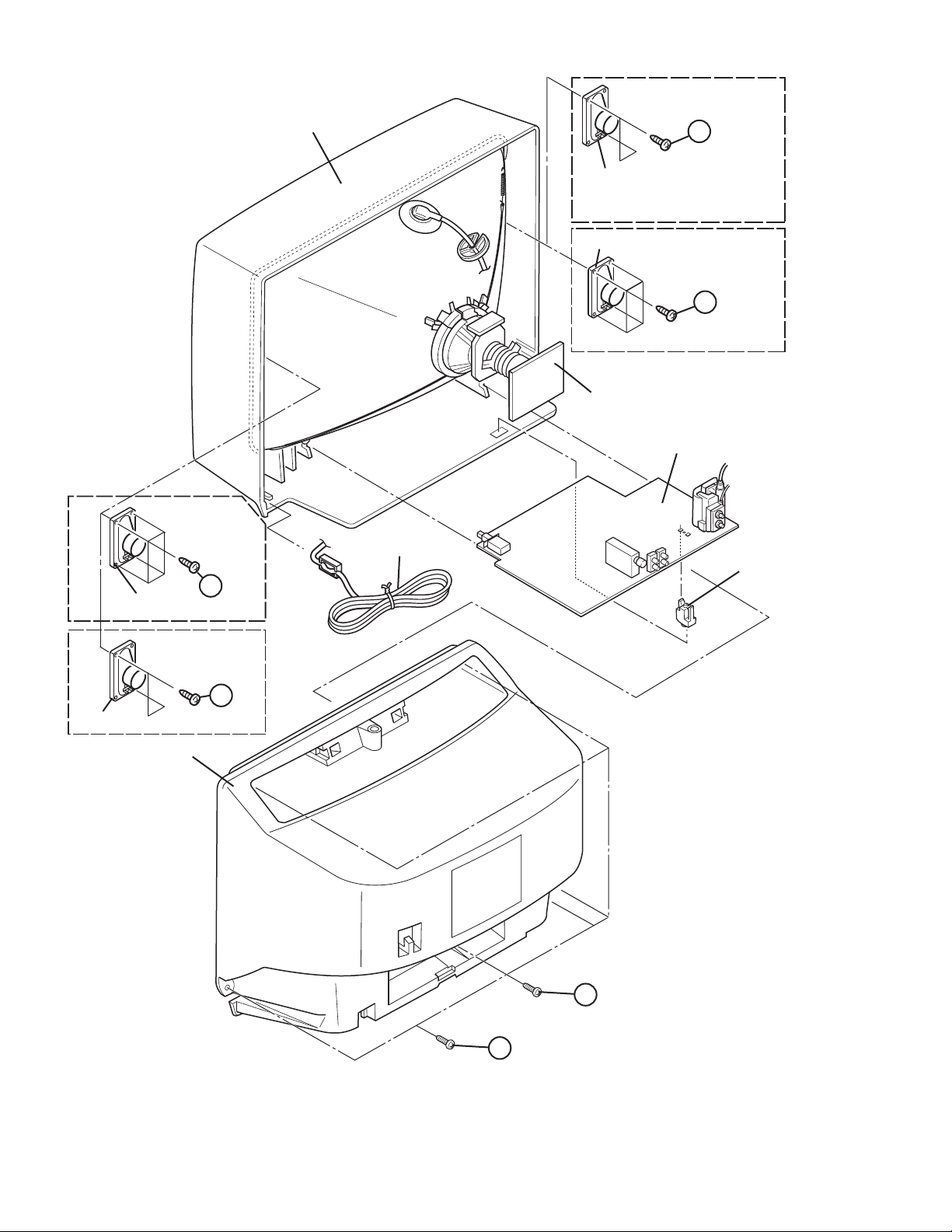
FRONT CABINET
C
(x2)
SPEAKER
AV-14146/N
AV-14149/N
AV-14FMG6/G
AV-14FMG6/S
C
(x4)
POWER CORD
SPEAKER
SPEAKER
CRT SOCKET PWB
(Within MAIN PWB)
MAIN PWB BOARD
AV-14146/N
AV-14149/N
AV-14FMG6/G
AV-14FMG6/S
(x4)
C
AV-1406FE
AV-14F16
PWB STOPPER
SPEAKER
AV-1406FE
AV-14F16
C
REAR COVER
(x2)
B
A
1-6 (No.YA370)
Fig.1
3.2 MEMORY IC REPLACEMENT
• This model uses the memory IC.
• This memory IC stores data for proper operation of the video and drive circuits.
• When replacing, be sure to use an IC containing this (initial value) data.
3.2.1 MEMORY IC REPLACEMENT PROCEDURE
1. Power off
Switch off the power and disconnect the power plug from the
AC outlet.
2. Replace the memory IC
Be sure to use the memory IC written with the initial setting
values.
3. Power on
Connect the power plug to the AC outlet and switch on the
power.
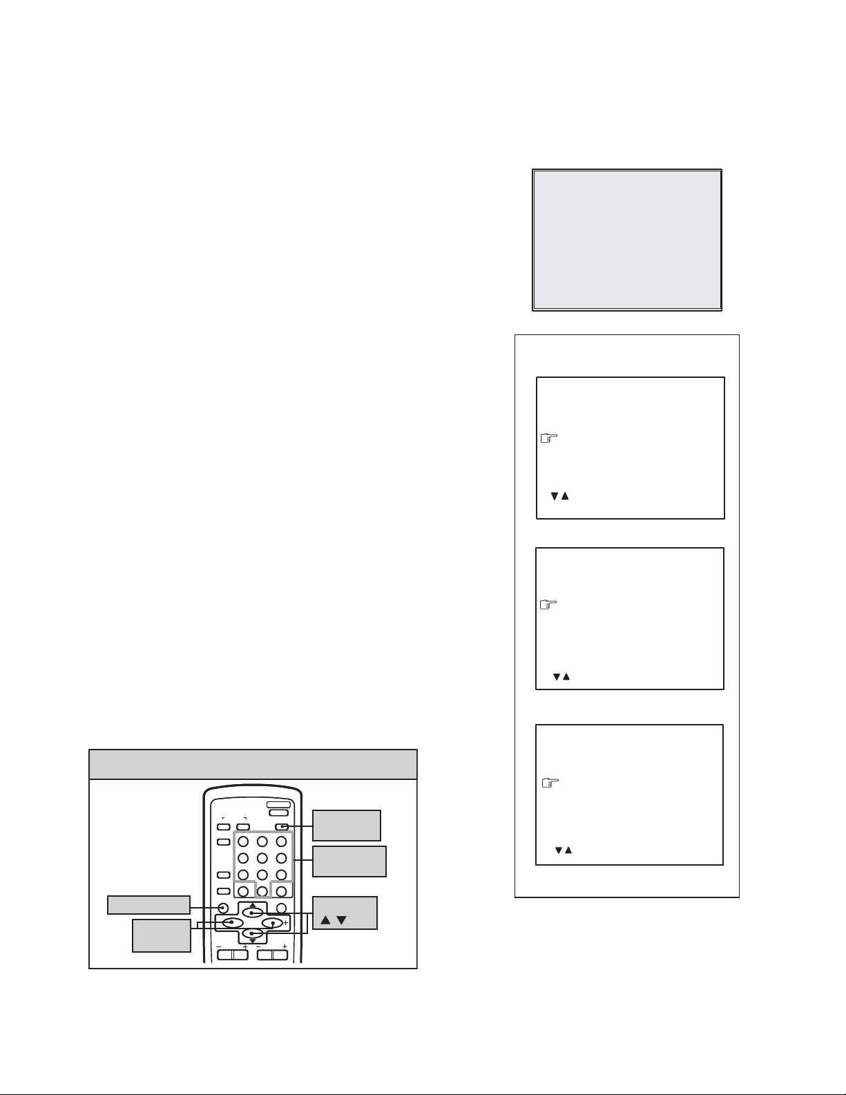
4. System constant check and setting
• It must not adjust without adjustment signals.
(1) Press the [DISPLAY] key and the [PICTURE MODE]
key of the REMOTE CONTROL UNIT simultaneously.
(2) The SERVICE MENU screen of Fig. 1 will be displayed.
(3) While the SERVICE MENU is displayed, again press the
[DISPLAY] key and [PICTURE MODE] key
simultaneously, and the SYSTEM CONSTANT SET
screen of Fig. 2 will be displayed.
(4) Check the setting values of the SYSTEM CONSTANT
SETTING. If the value is different, select the setting item
with the [MENU /] key, and set the correct value with
the [MENU - / +] key.
(5) Press the [DISPLAY] key twice, and return to the normal
screen.
5. Receiving channel setting
Refer to the OPERATING INSTRUCTIONS and set the
receive channels (Channels Preset) as described.
6. User settings
Check the user setting items according to the given in page
later.
Where these do not agree, refer to the OPERATING
INSTRUCTIONS and set the items as described.
7. SERVICE MENU setting
Verify what to set in the SERVICE MENU, and set whatever is
necessary (Fig.1).
Refer to the SERVICE ADJUSTMENT for setting.
SERVICE MENU
1.IF 2.V/C
3.DEF 4.VSM PRESET
5.PRESET
6.SETUP TOUR OFF
1-6 : SELECT DISP : EXIT
************ **.***
*** ** **** ***
Fig.1
SYSTEM CONSTANT- I
SYSTEM CONSTANT SET 1
COLOUR : TRIPLE
BILINGUAL : NO
TUNER : MU
ECO SENSOR
LANGUAGE : E/R/U
: SELECT
/
- / + : OPERATE DISP : EXIT
SYSTEM CONSTANT- II
SYSTEM CONSTANT SET 2
B/B SOUND : OFF
LOCK : 180
COLOUR AUTO
QSS
ALC : NO
TEXT RATE
: SEL - / + : OPE DISP : EXIT
/
SYSTEM CONSTANT- III
: NO
: NO
: MINT
: 20
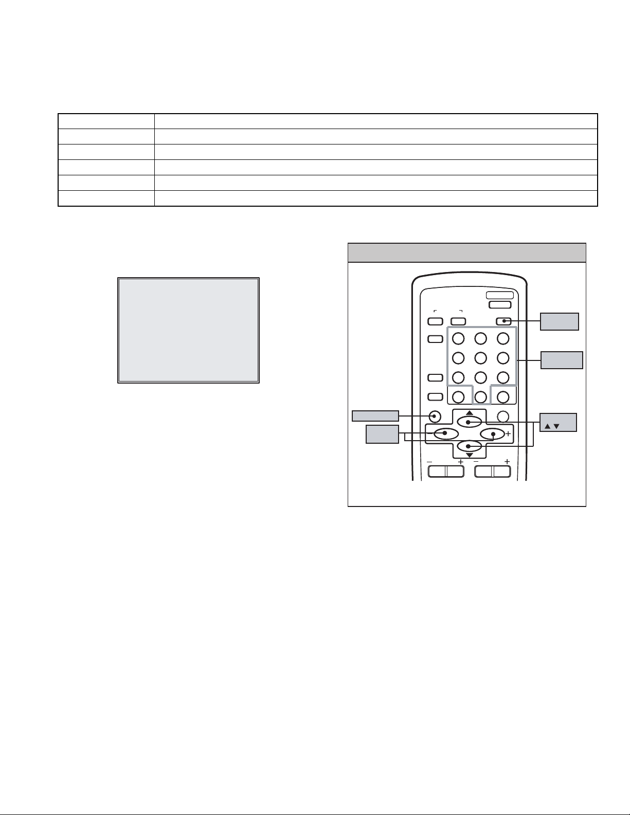
KEY ASSIGNMENT OF REMOTE CONTROL UNIT
POWER
SOUND
123
456
789
RETURN+
0
MENU
MENU
VOLUME
PICTURE
MODE
MUTING
PICTURE
MODE key
NUMBERS
key
-/--
MENU
/ key
DISPLAY key
MENU
- / + key
COLOUR
TV/VIDEO
OFF
TIMER
CHANNEL
SCAN
DISPLAY
CHANNEL
SYSTEM
SYSTEM CONSTANT SET 3
AMP TUNER : NO
VNR
TEXT TABLE : CYL
VOLUME PWM : POS
/
: SEL - / + : OPE DISP : EXIT
: YES
Fig.2
(No.YA370)1-7
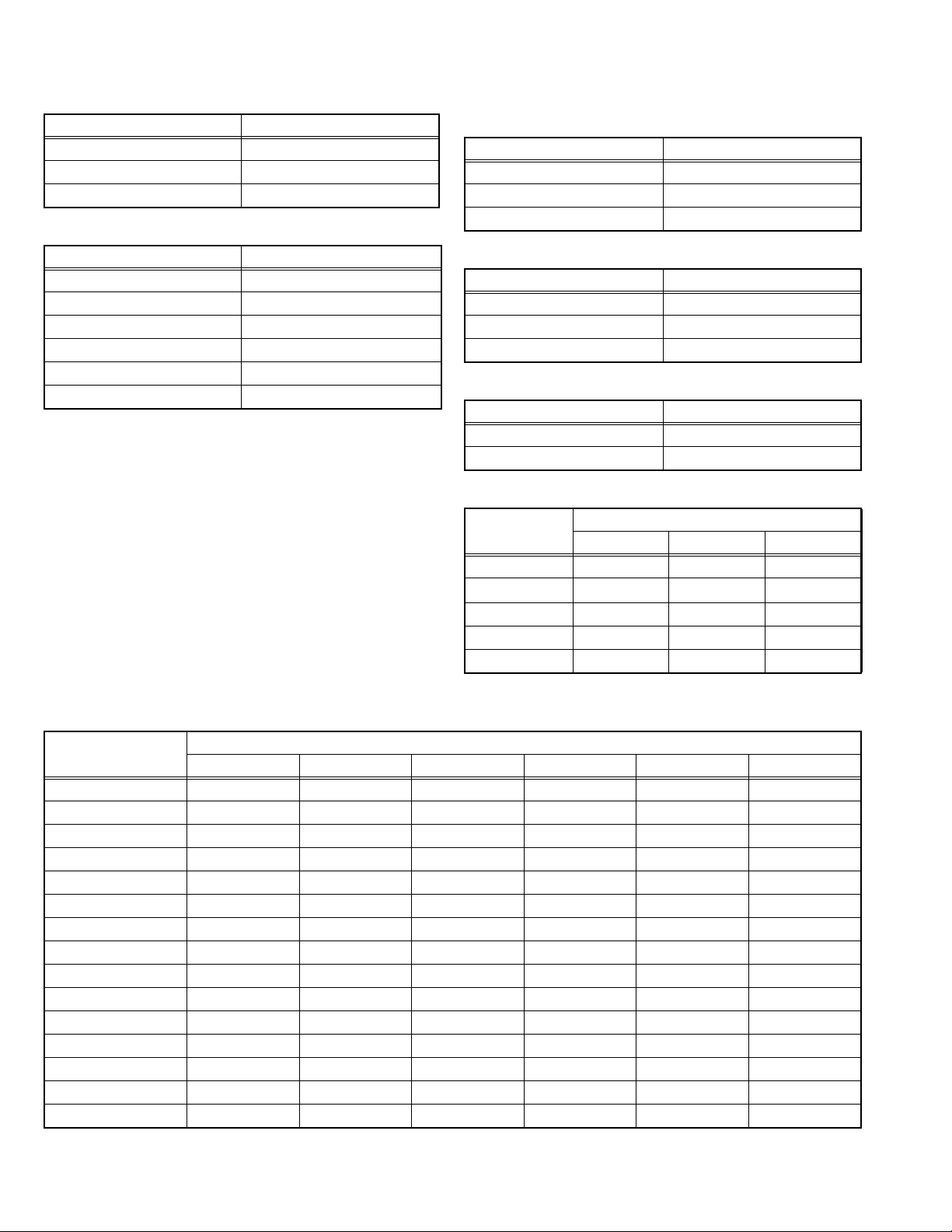
3.2.2 SETTINGS OF FACTORY SHIPMENT
3.2.2.1 BUTTON OPERATION
Setting item Setting position
POWER Off
CHANNEL PR1
VOLUME 10
3.2.2.2 REMOTE CONTROL DIRECT OPERATION
Setting item Setting position
CHANNEL PR1
VOLUME 10
TV/VIDEO TV
PICTURE MODE BRIGHT
COLOUR SYSTEM PAL
SOUND SYSTEM B/G
3.2.2.3 REMOTE CONTROL MENU OPERATION
(1) MENU-1
Setting item Setting position
INPUT TV
ON TIMER PR1 0:00
VNR OFF
(2) MENU-2
Setting item Setting position
AUTO SHUTOFF OFF
CHILD LOCK OFF
BLUE BACK OFF
(3) MENU-3
Setting item Setting position
SETUP TOUR ON
LANGUAGE ENGLISH
(4) MENU-4
Setting item
TINT 15 15 15
COLOUR
BRIGHT 15 15 15
CONT. 30 15 13
SHARP 15 15 12
BRIGHT STANDARD SOFT
15 15 15
Setting position
3.2.3 SYSTEM CONSTANT SETTING
Setting item
COLOUR TRIPLE ←←←MULTI ←
BILINGUAL NO ←←←←←
TUNER MU ←←←←←
ECO SENSOR NO ←←←←←
LANGUAGE E / R / U E / C / M / I ←←E / R / A / P ←
B/B SOUND OFF ←←←←ON
LOCK 180 ←←←←←
COLOUR AUTO NO ←←←←YES
QSS MINT ←←←←←
ALC NO ←←←←←
TEXT RATE 20 ←←←←←
AMP TUNER NO ←←←←←
VNR YES ←←←←←
TEXT TABLE CYL ←←←←←
VOLUM PWM POS ←←←←←
AV-1406FE AV-14146/N AV-14149/N AV-14F16
Setting value
AV-14FMG6/G AV-14FMG6/S
1-8 (No.YA370)
3.2.4 SERVICE MENU SETTING ITEMS
Setting item Setting value Setting item Setting value
2. V/C 1.CUT OFF
2.DRIVE
3.BRIGHT
4.CONT.
5.COLOUR
6.TINT
7.SECAM BL ADJUST
8.SHARP [Do not adjust]
3. DEFLECTION 1. VER. POSITION
2. HOR. POSITION
3. VER. HEIGHT
4. VER. LINEARITY
5. VER. SCURVE
6. HOR. VCO ADJUST [Do not adjust]
4.VSM PRESET TINT
COLOUR
BRIGHT
CONT.
SHARP
5. PRESET
[Do not adjust]
Colour System 1. C-TRAP FIX
2. SHARP PEAK
3. ABL
4. GAMMA
5. Y. DELAY TIME
6. BLACK EXP START
7. C-BPF
8. CW / SCP
9. VIF DET LEVEL
11. IF AGC MIN
12. VIF AGC
13. VIF PMOD
19. VNR
20. RGB LIM
21. RGB LIMIT LEVEL
23. TEXT H. POSITION
24. READ DATA
Sound System 10. SIF DET LEVEL
14. SIF BPF BW ADJUST
15. SIF TRAP F0 ADJUST
16. SIF TRAP F0 ADJUST 2
17. SIF -TRAP
18. SIF -BPF
22. SIF SW
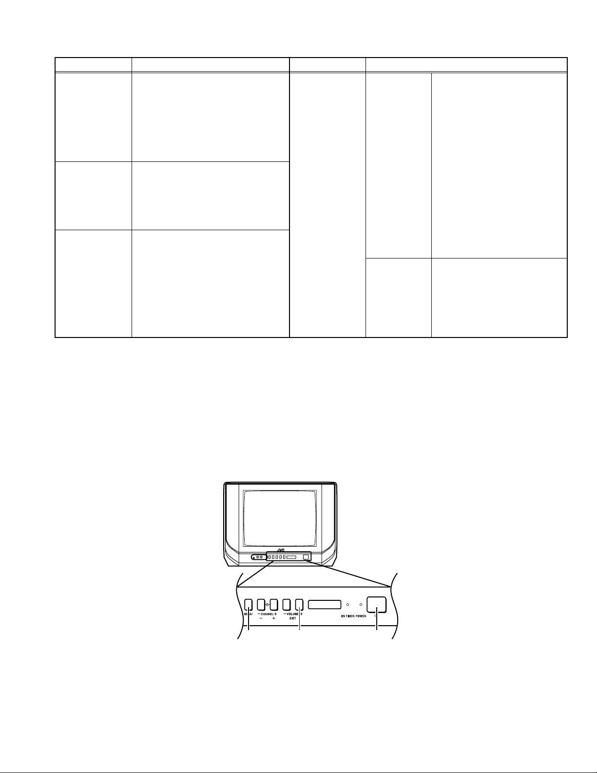
3.2.5 REPLACEMENT OF IC301 (IF V/C DECODER)
• For the IC301(IF V/C DECODER) of this model, all data are written in the micro-computer. So, write the data in the micro-
computer in accordance with the following procedures before starting adjustment.
PROCEDURES
(1) Turn the POWER OFF.
(2) Replace the IC301 with a new one.
(3) While pressing [MENU] button and [VOL+] button ON the FRONT CABINET simultaneously, turn the POWER ON. When the
POWER is turned ON, the data is written in the micro-computer immediately.
LOCATIONS OF FRONT PANEL BUTTONS
VOLUME + POWERMENU
(No.YA370)1-9
3.3 REPLACEMENT OF CHIP COMPONENT
3.3.1 CAUTIONS
(1) Avoid heating for more than 3 seconds.
(2) Do not rub the electrodes and the resist parts of the pattern.
(3) When removing a chip part, melt the solder adequately.
(4) Do not reuse a chip part after removing it.
3.3.2 SOLDERING IRON
(1) Use a high insulation soldering iron with a thin pointed end of it.
(2) A 30w soldering iron is recommended for easily removing parts.
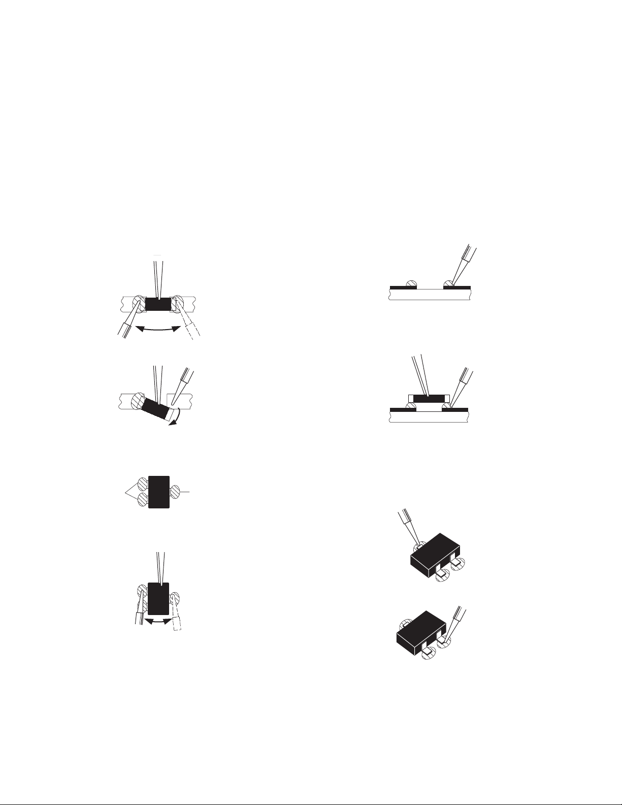
3.3.3 REPLACEMENT STEPS
1. How to remove Chip parts
2. How to install Chip parts
[Resistors, capacitors, etc.]
(1) As shown in the figure, push the part with tweezers and
alternately melt the solder at each end.
(2) Shift with the tweezers and remove the chip part.
[Transistors, diodes, variable resistors, etc.]
(1) Apply extra solder to each lead.
SOLDER
SOLDER
[Resistors, capacitors, etc.]
(1) Apply solder to the pattern as indicated in the figure.
(2) Grasp the chip part with tweezers and place it on the
solder. Then heat and melt the solder at both ends of the
chip part.
[Transistors, diodes, variable resistors, etc.]
(1) Apply solder to the pattern as indicated in the figure.
(2) Grasp the chip part with tweezers and place it on the
solder.
(3) First solder lead A as indicated in the figure.
(2) As shown in the figure, push the part with tweezers and
alternately melt the solder at each lead. Shift and remove
the chip part.
NOTE :
After removing the part, remove remaining solder from the
pattern.
1-10 (No.YA370)
A
B
C
(4) Then solder leads B and C.
A
B
C
SECTION 4
ADJUSTMENT
4.1 ADJUSTMENT PREPARATION
(1) There are 2 ways of adjusting this TV : One is with the
REMOTE CONTROL UNIT and the other is the
conventional method using adjustment parts and
components.
(2) The adjustment using the REMOTE CONTROL UNIT is
made on the basis of the initial setting values. The
setting values which adjust the screen to the optimum
condition can be different from the initial setting
values.
(3) Make sure that connection is correctly made AC to AC
power source.
(4) Turn on the power of the TV and measuring instruments for
warming up for at least 30 minutes before starting
adjustments.
(5) If the receive or input signal is not specified, use the most
appropriate signal for adjustment.
(6) Never touch the parts (such as variable resistors,
transformers and condensers) not shown in the adjustment
items of this service adjustment.
4.2 PRESET SETTING BEFORE ADJUSTMENT
Unless otherwise specified in the adjustment items, preset the
following functions with the REMOTE CONTROL UNIT.
Item Preset value
PICTURE MODE STANDARD
TINT / COLOUR / BRIGHT / CONT. / SHARP Centre
VNR OFF
BLUE BACK OFF
OFF TIMER OFF
AUTO SHUT OFF OFF
4.3 MEASURING INSTRUMENT AND FIXTURES
(1) DC voltmeter (or digital voltmeter)
(2) Oscilloscope
(3) Signal generator
(Pattern generator : PAL / SECAM / NTSC)
(4) Remote control unit
4.4 ADJUSTMENT ITEMS
CHECK ITEM
• B1 VOLTAGE check
TUNER / IF CIRCUIT
• IF VCO adjustment
• DELAY POINT adjustment
FOCUS
• FOCUS adjustment
DEFLECTION CIRCUIT
• V.HEIGHT / V.POSITION adjustment
• H. POSITION adjustment
• V.LINEARITY / V.S-CURVE adjustment
VIDEO CIRCUIT
• WHITE BALANCE adjustment
• SUB BRIGHT adjustment
• SUB CONTRAST adjustment
• SUB COLOUR adjustment
• SUB TINT adjustment
• SECAM BALACK OFFSET adjustment
VSM PRESET SETTING
• VSM PRESET setting
(No.YA370)1-11
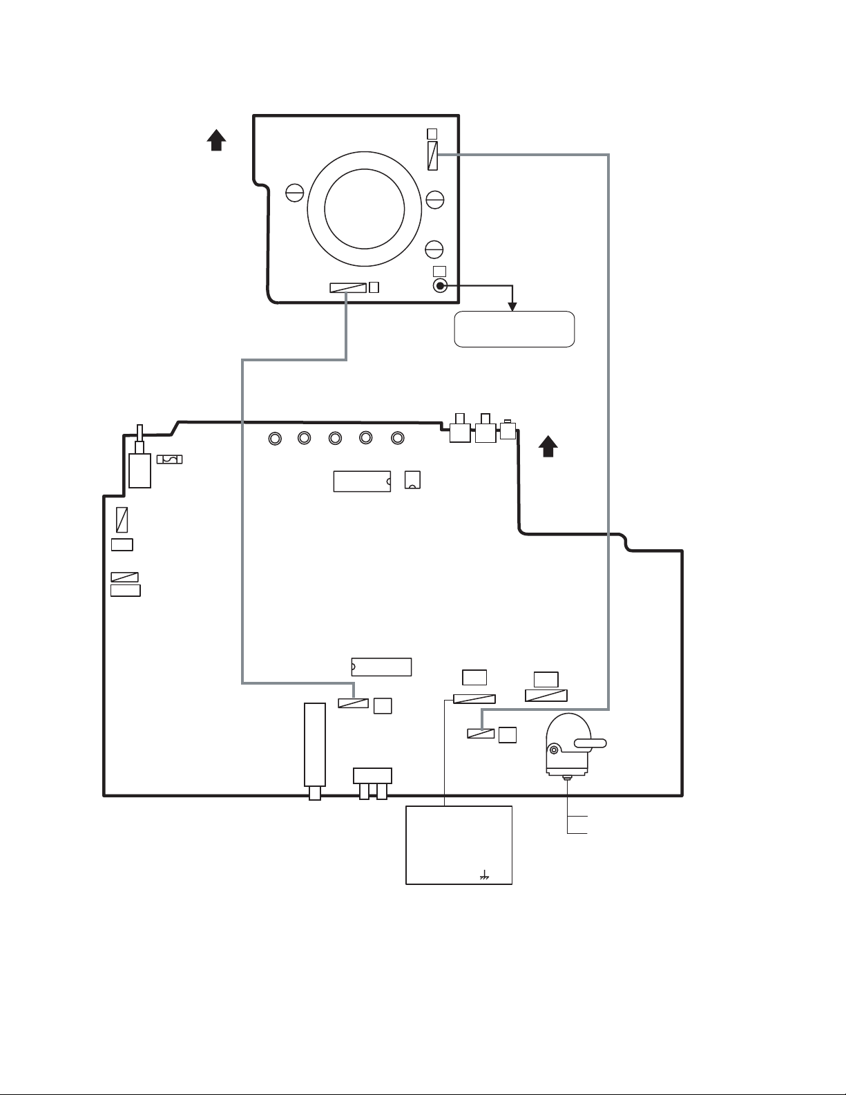
4.5 ADJUSTMENT LOCATIONS
F901
TOP
CRT SOCKET PWB
TP-47G/R
T
IC701
(SOLDER SIDE)
U
TP-47B
TP-E
E1
CRT EARTH WIRE
(BRAIDED ASS'Y)
FRONT
IC702
MEMORY IC
PW
DEG
MAIN PWB
TU001
IC301
T
1Pin TP-91(B1)
2Pin NC
3Pin X-ray1
4Pin X-ray2
5Pin TP-E( )
S1
51
U
HV
HVT
UPPER:FOCUS
LOWER:SCREEN
1-12 (No.YA370)
4.6 BASIC OPERATION OF SERVICE MENU
4.6.1 TOOL OF SERVICE MENU OPERATION
Operate the SERVICE MENU with the REMOTE CONTROL UNIT.
4.6.2 SERVICE MENU ITEMS
With the SERVICE MENU, various adjustments can be made, and they are broadly classified in the following items of settings.
1.IF Adjustment of the IF circuits.
2.V/C Adjustment of the VIDEO circuit.
3.DEF Adjustment of the DEFLECTION circuit.
4.VSM PRESET Adjustment of the initial setting values of VSM condition as STANDARD, SOFT and BRIGHT.
5.PRESET Adjustment of the RF circuit [Do not adjust].
6.SETUP TOUR It should be able to select mode (LANGUAGE and AUTO CH PRESET) [Should be OFF].
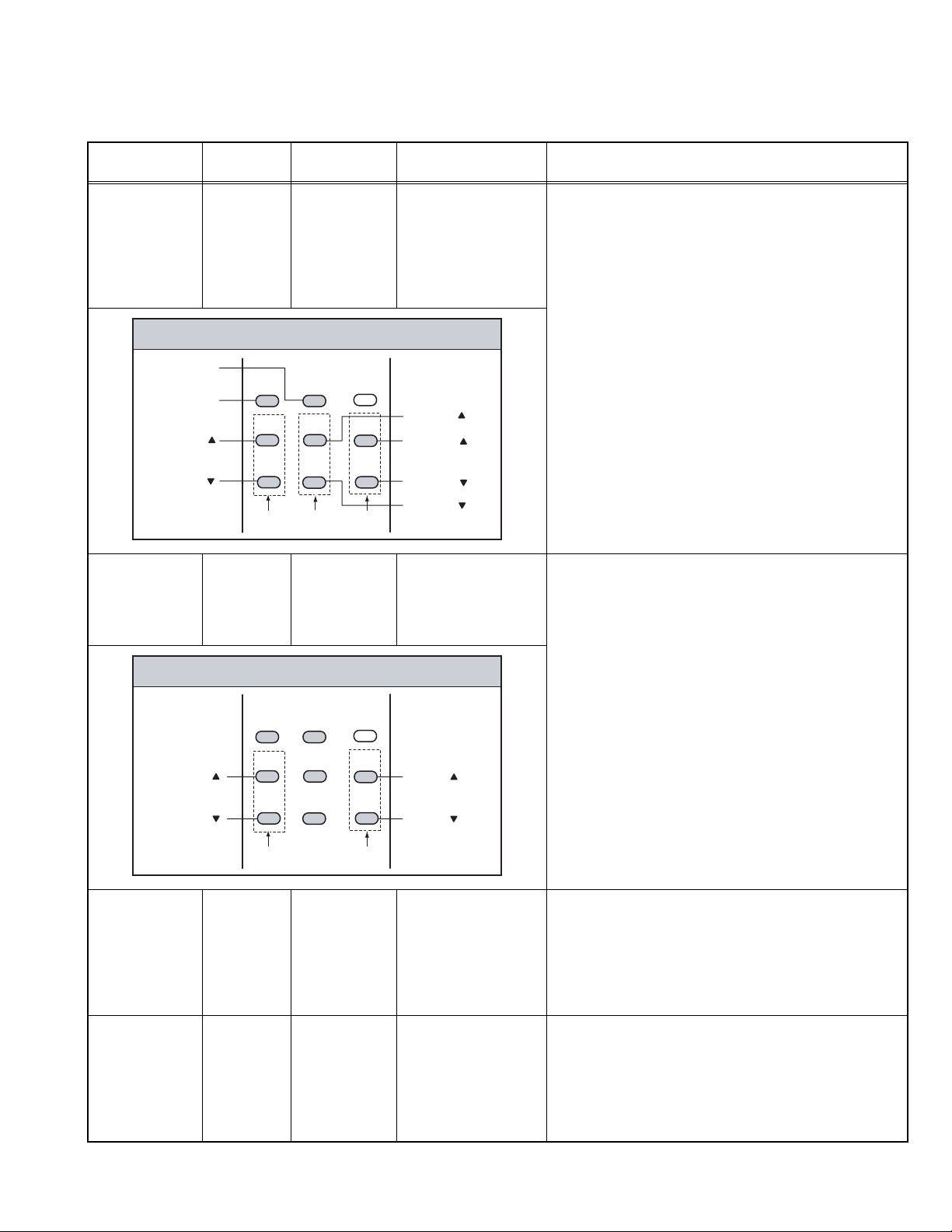
4.6.3 HOW TO ENTER THE SERVICE MENU
Press the [DISPLAY] key and the [PICTURE MODE] key of
the REMOTE CONTROL UNIT simultaneously. Then enter the
SERVICE MODE SELECT KEY
SERVICE MENU mode as shown in Fig.1.
POWER
SERVICE MENU
1.IF 2.V/C
3.DEF 4.VSM PRESET
5.PRESET
6.SETUP TOUR OFF
1-6 : SELECT DISP : EXIT
************ **.***
*** ** **** ***
Fig.1
4.6.4 HOW TO STORE OF SETTING VALUE
The setting value will be stored automatically when release the
REMOTE CONTROL UNIT keys
DISPLAY key
MENU
- / + key
SYSTEM
COLOUR
TV/VIDEO
OFF
TIMER
CHANNEL
SCAN
DISPLAY
CHANNEL
SOUND
RETURN+
MENU
MENU
PICTURE
123
456
789
0-/
MUTING
VOLUME
MODE
PICTURE
MODE key
NUMBERS
key
--
MENU
/ key
4.6.5 HOW TO EXIT THE SERVICE MENU
When complete the adjustment work, press the [DISPLAY]
key to return to the SERVICE MENU. And then press the
[DISPLAY] key again, return to the normal screen.
4.6.6 SELECTION OF SUB MENU SCREEN
Press one of [1] to [5] keys of the REMOTE CONTROL UNIT
and select the SUB MENU SCREEN form the SERVICE
MENU.
(No.YA370)1-13

4.6.7 METHOD OF SETTING
1. IF
[1. VCO]
(1) [1] key Select 1. IF.
(2) [1] key Select 1. VCO.
(3) [MENU /] keys Select setting items.
(4) [MENU - / +] keys Adjust the values of the items.
(5) [DISPLAY] key As you press this key twice, you will return to the SERVICE MENU.
[2. DELAY POINT]
(1) [1] key Select 1. IF.
(2) [2] key Select 2. DELAY POINT.
(3) [MENU - / +] keys Set (adjust) the setting values of the setting items.
(4) [DISPLAY] key When this is pressed twice, you will return to the SERVICE MENU.
NOTE:
When the setting value has been changed, the new value will be stored in memory immediately.
2. V/C, 3. DEF and 4. VSM PRESET
(1) [2] to [4] keys Select one from 2. V/C, 3. DEF and 4. VSM PRESET.
(2) [MENU /] keys Select setting items.
(3) [MENU - / +] keys Adjust the values of the items.
(4) [DISPLAY] key When this is pressed, return to the SERVICE MENU.
NOTE:
When the setting value has been changed, the new value will be stored in memory immediately.
5. PRESET (Do not adjust)
6. SETUP TOUR
(1) By pressing the [6] key, you can change the ON or OFF [should be OFF].
Should be OFF:
If it is ON, when you turn off the power and turn on a power again, the JVC’s logo will be shown
about 15 seconds automatically, and the SETUP TOUR starts.
(2) [MENU - / +] keys Select Language.
(3) [MENU ] key Auto Search.
1-14 (No.YA370)
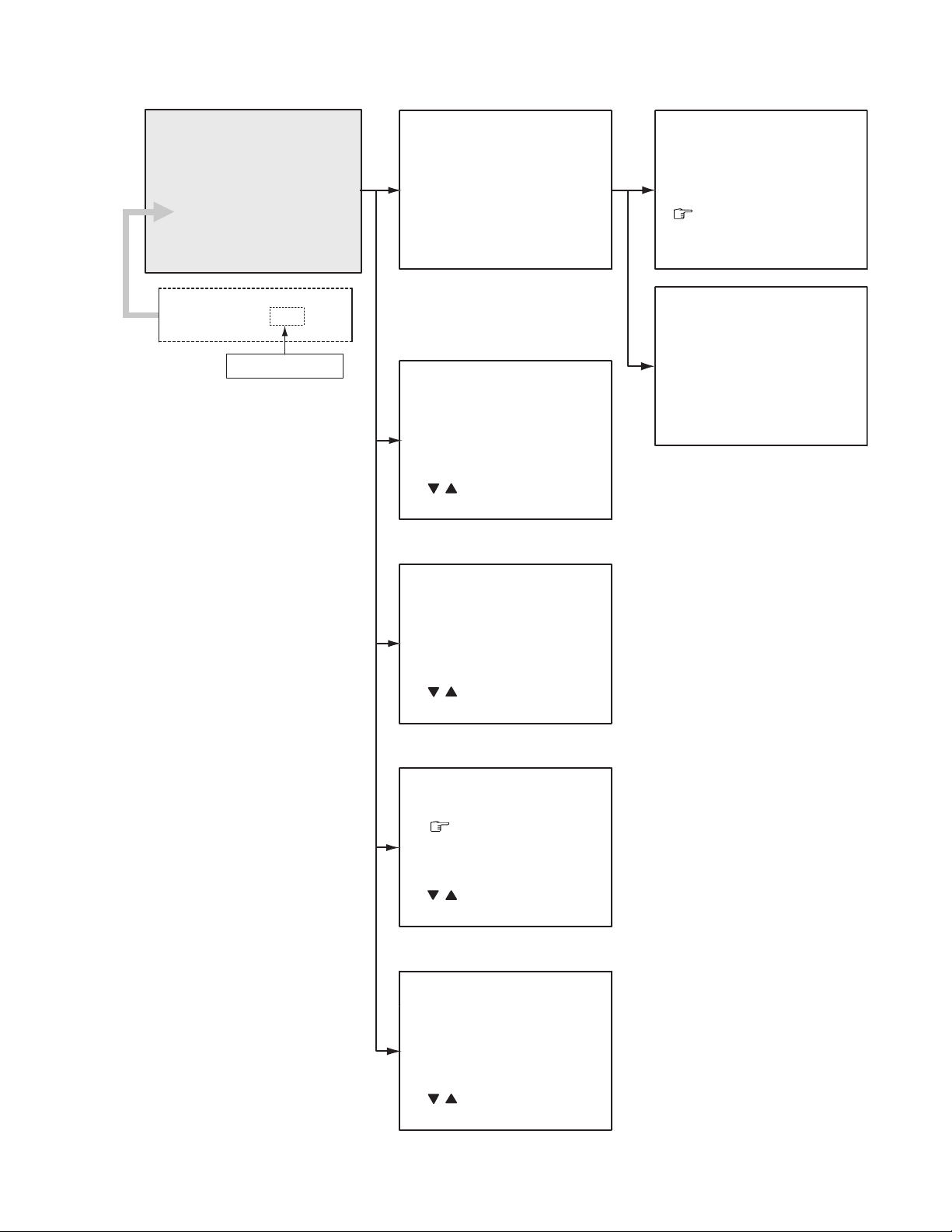
4.6.8 SERVICE MENU FLOW CHART
************ **.***
SERVICE MENU
1. IF
SERVICE MENU
1.IF 2.V/C
3.DEF 4.VSM PRESET
5.PRESET
6.SETUP TOUR OFF
1-6 : SELECT DISP : EXIT
************ **.***
6. SETUP TOUR OFF
*** ** **** ***
ON / OFF
(By pressing [6] key)
IF
1. VCO
2. DELAY POINT
1-2 : SELECT DISP : EXIT
2. V/C
V/C PAL
1. CUTOFF
(G)
(B)
50Hz
/ : SELECT
- / + : OPERATE DISP : EXIT
(R)
* **
* **
* **
3. DEF
VCO (CW)
TOO HIGH
ABOVE REFERENCE
JUST REFERENCE
BELOW REFERENCE
TOO LOW
AFT ADJUST
VCO ADJUST
FINE
DISP : EXIT
DELAY POINT UHF
AGC TAKE-OVER
- / + : OPERATE DISP : EXIT
***.**
MHz
*** (**
*** (**
**
)
)
DEF PAL
1. VER. POSITION
50Hz
/ : SELECT
- / + : OPERATE DISP : EXIT
**
4. VSM PRESET
BRIGHT
TINT
COLOUR
BRIGHT
CONT.
SHARP
/ : SELECT
- / + : OPERATE DISP : EXIT
**
**
**
**
**
5. PRESET
PRESET PAL
1. C-TRAP FIX
*
50Hz B/G
/ : SELECT
- / + : OPERATE DISP : EXIT
(No.YA370)1-15
4.7 INITIAL SETTING VALUE OF SERVICE MENU
• Adjustment of the SERVICE MENU is made on the basis of the initial setting values ; however, the new setting values which
set the screen in its optimum condition may differ from the initial setting.
• Do not change the initial Setting Values of the Setting (Adjustment) items not listed in "ADJUSTMENT PROCEDURE".
[2. V/C]
Setting item Variable range
1.CUT OFF RED -128 - +127 -50 -50 -50 -50
GREEN -128 - +127 -50 -50 -50 -50
BLUE -128 - +127 -50 -50 -50 -50
2.DRIVE RED -128 - +127 +0 +0 +0 +0
BLUE -128 - +127 +0 +0 +0 +0
3.BRIGHT -128 - +127 +0 +0 +0 +0
4.CONT. -63 - +63+0+0+0+0
5.COLOUR -63 - +63 +0 +0 +0 0
6.TINT TV -63 - +63 --- --- +0 0
VIDEO -63 - +63 --- --- +0 0
7.SECAM BL ADJUST -31 - +31 +0 +0 +0 +0
8.SHARP
(Do not adjust)
[3. DEFLECTION]
1. VER. POSITION -4 - +3 +0 -3
2. HOR. POSITION -16 - +15 +1 +4
3. VER. HEIGHT -64 - +63 -20 -2
4. VER. LINEARITY -32 - +31 +15 +0
5. VER. SCURVE -32 - +31 -32 +0
6. HOR. VCO ADJUST
TV -31 - +31 -17 (Fixed) -17 (Fixed) -17 (Fixed) -17 (Fixed)
VIDEO -31 - +31 +10 (Fixed) +10 (Fixed) +10 (Fixed) +10 (Fixed)
Setting item Variable range
[Do not adjust]
-63 - +63 -32 +0
PAL SECAM NTSC 3.58 NTSC 4.43
Initial setting value
fv : 50Hz fv : 60Hz
Initial setting value
[4.VSM PRESET]
Setting item Variable range
TINT 0 - 30 15 15 15
COLOUR 0 - 30 15 15 15
BRIGHT 0 - 30 15 15 15
CONT. 0 - 30 30 15 13
SHARP 0 - 30 15 15 12
1-16 (No.YA370)
BRIGHT STANDARD SOFT
Initial setting value

[5. PRESET]
The items in the following table, it is no requirement for adjustment.If values had changed by the miss operation, set the
initial setting values in the following table.
z COLOUR SYSTEM (Do not adjust)
Setting item Variable range
1. C TRAP FIX 0 - 1 1 1 1 1
2. SHARP PEAK 0 - 1 0 0 0 0
3. ABL 0 - 11111
4. GAMMA 0 - 1 0 0 0 0
5. Y. DELAY TIME TV 0 - 3 0 2 2 3
VIDEO 0 - 30202
6. BLACK EXP START 0 - 3 3 3 3 3
7. C-BPFTV 0 - 11100
VIDEO 0 - 11111
8. CW / SCP 0 - 1 0 0 0 0
9. VIF DET LEVEL -63 - +63 +0 +0 +0 +0
11. IF AGC MIN 0 - 1 0 0 0 0
12. VIF AGC 0 - 1 0 0 0 0
13. VIF PMOD 0 - 1 0 0 0 0
19. VNR 0 - 63 15 15 15 15
20. RGB LIM 0 - 1 1 1 1 1
21. RGB LIMIT LEVEL 0 - 7 2 2 2 2
23. TEXT H. POSITION -16 - +15 -3 -3 -3 -3
24. READ DATA --- --- --- --- ---
PAL SECAM NTSC 3.58 NTSC 4.43
Initial setting value (Fixed value)
z SOUND SYSTEM (Do not adjust)
Setting item Variable range
10. SIF DET LEVEL -7 - +7 +0 +0 +0 +0
14. SIF BPF BW ADJUST -7 - +7 +0 +0 +0 +0
15. SIF TRAP FO ADJUST -7 - +7 +0 +0 +0 +0
16. SIF TRAP FO ADJUST 2 -7 - +7 +0 +0 +0 +0
17. SIF -TRAP 0 - 10000
18. SIF -BPF 0 - 10001
22. SIF SW 0 - 11110
B/G I D/K M
Initial setting value (Fixed value)
(No.YA370)1-17
4.8 ADJUSTMENT PROCEDURE
4.8.1 CHECK ITEM
Item
B1 VOLTAGE Signal
Measuring
instrument
generator
DC voltmeter
TP-B1 : 1-pin
TP-E : 5-pin
(S1 connector)
[MAIN PWB]
4.8.2 TUNER / IF CIRCUIT
Test point Adjustment part Description
(1) Receive a whole black signal.
(2) Connect a DC voltmeter to 1-pin and 5-pin of S1
connector.
(3) Make sure that the voltage is DC116.2V±2.0V.
Item
Measuring
instrument
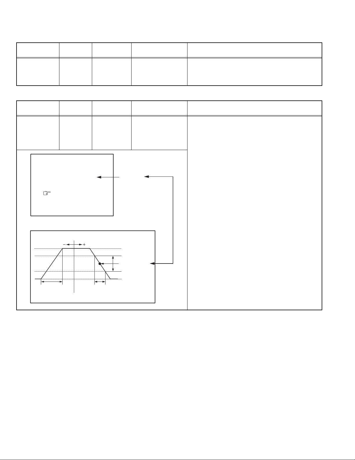
IF VCO Signal
generator
Remote
control unit
VCO (CW)
TOO HIGH
ABOVE REFERENCE
JUST REFERENCE
BELOW REFERENCE
TOO LOW
AFT ADJUST
VCO ADJUST
FINE
DISP : EXIT
ADJUSTMENT AT THIS POINT
IS USELESS
***.**
Test point Adjustment part Description
[1. IF]
1. VCO
• Please use signal generator which is correct proof about
the sending frequency.
(1) Receive any broadcast.
(2) Select 1.IF from the SERVICE MENU.
(3) Select < 1.VCO >.
(4) Select VCO ADJUST with [MENU /] key.
MHz
(5) Press [MENU - / +] keys until the colour of the
characters TOO HIGH changes blue to yellow. Then
gradually press the [MENU - / +] keys until the TOO
YELLOW
LOW changes yellow. At this time, confirm that the
value of VCO ADJUST is near +00.
***(**
***(**
)
)
(6) Select AFT ADJUST with [MENU /] key.
(7) Press [MENU - / +] keys until the characters JUST
REFERENCE changes blue to yellow.
(8) Press the [DISPLAY] key three times to return to
normal screen.
TOO HIGH
ABOVE REFERENCE
JUST REFERENCE
BELOW REFERENCE
TOO LOW
ADJUSTMENT POINT
1-18 (No.YA370)
Item
DELAY POINT
(AGC)
Measuring
instrument
Test point Adjustment part Description
Signal
generator
Remote
control unit
DELAY POINT UHF
AGC TAKE-OVER **
- / + : OPERATE DISP : EXIT
[1. IF]
2. DELAY POINT
(AGC TAKE-OVER)
(1) Receive a black and white signal (colour off).
(2) Select 1. IF.
(3) Select < 2. DELAY POINT >.
(4) Set the setting values of the setting items as shown
bellow table.
(5) Then adjust the [MENU - / +] keys until video noise
disappears.
(6) Turn to other channels and make sure that there are
no irregularities.
Setting Item
DELAY POINT
(AGC TAKE-OVER)
NTSC3.58
OTHER
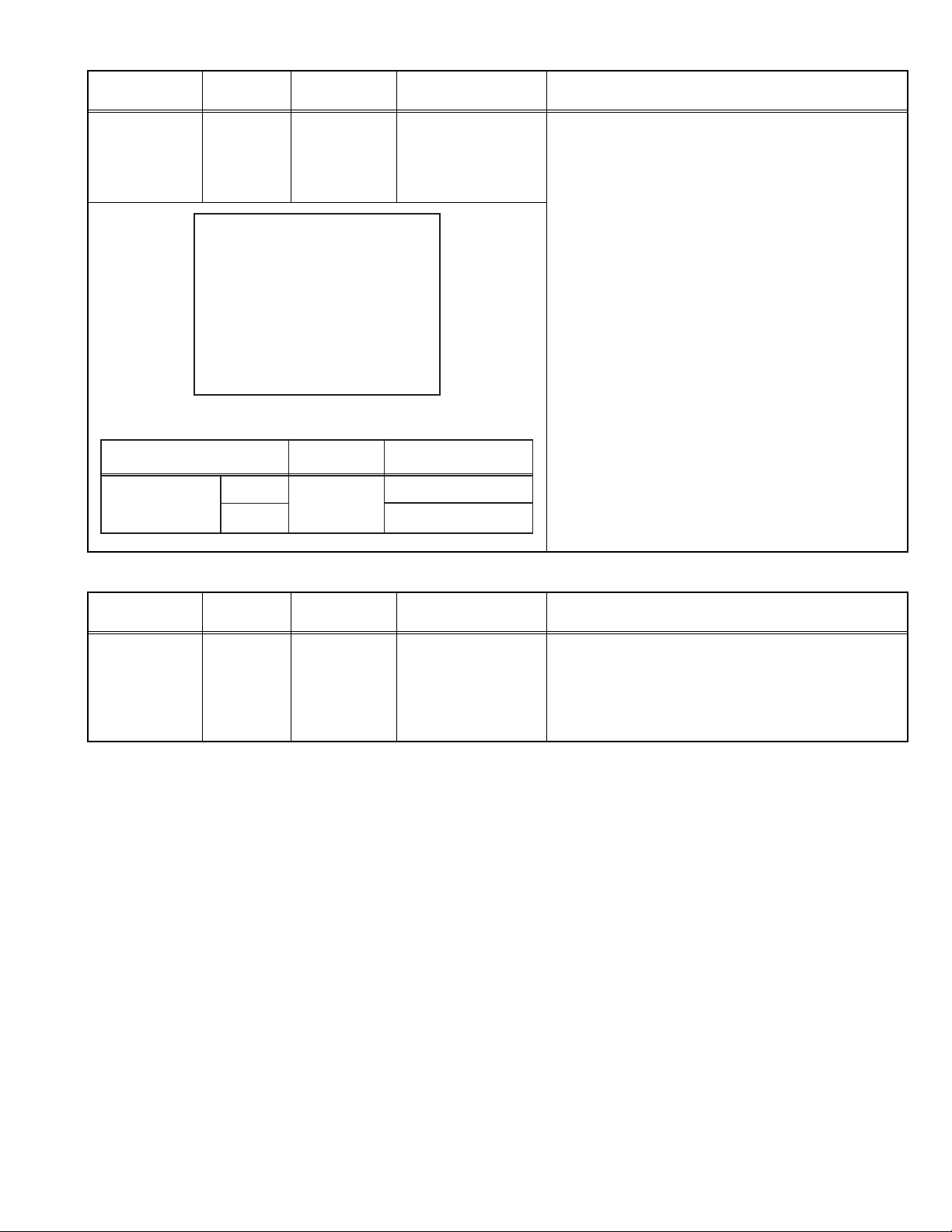
4.8.3 FOCUS
Item
Measuring
instrument
FOCUS Signal
generator
Variable range
0 - 127
Initial setting value
45
35
Test point Adjustment part Description
FOCUS VR
[In HVT]
(1) Receive a crosshatch signal.
(2) While watching the screen, adjust the FOCUS VR to
make the vertical and horizontal lines as fine and
sharp as possible.
(3) Make sure that when the screen is darkened, the
lines remain in good focus.
(No.YA370)1-19
4.8.4 DEFLECTION CIRCUIT
• There are 2 modes of adjustment (setting value) 50Hz mode and 60Hz mode, depending upon the kind of signals (vertical frequency
50Hz / 60Hz).
• When adjusted in 50Hz mode and 60Hz mode will be automatically set.
The setting (adjustment) using the REMOTE CONTROL UNIT is made on the basis of the initial setting values.The setting
values which adjust the screen to the optimum condition can be different from the initial setting values.
• Make sure that the adjustment is properly done on the screen of 60Hz mode.
NOTE:
• Adjust to make both 50Hz & 60Hz are the same v. size and fine straight line.
• When adjust again, adjust 50Hz mode first.
• When adjust in 60Hz mode, only 60Hz mode is adjust.
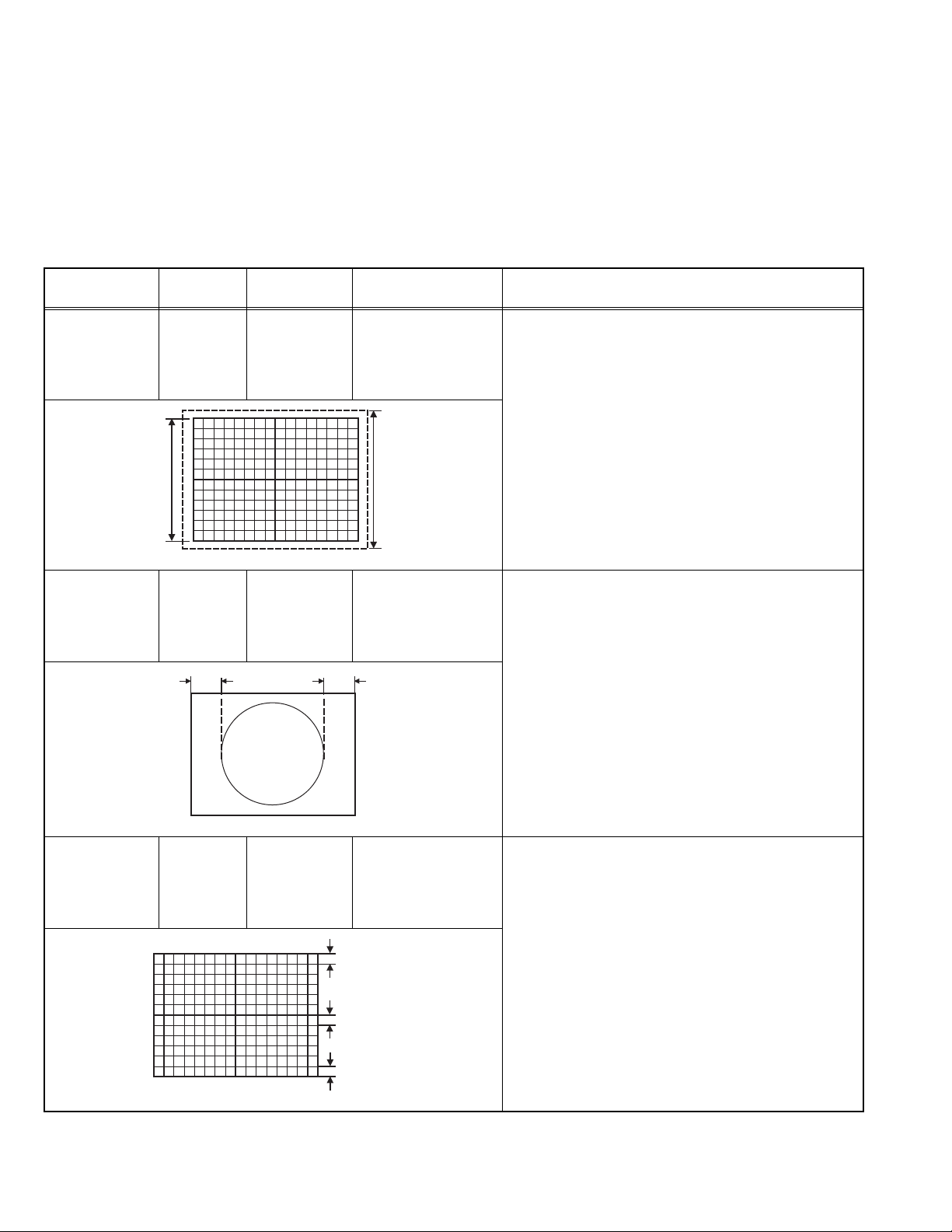
Item
V. HEIGHT /
V. POSITION
Measuring
instrument
Signal
generator
Remote
control unit
Test point Adjustment part Description
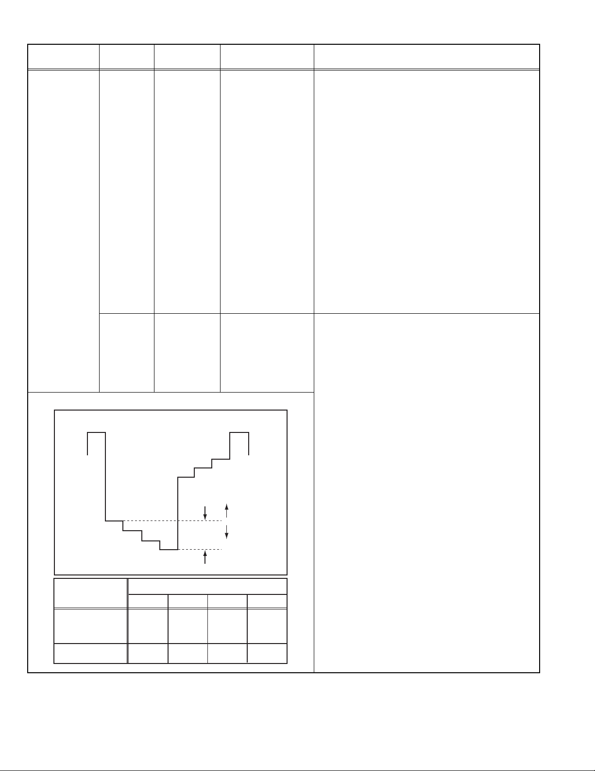
[3. DEF]
1. VER. POSITION
3. VER. HEIGHT
(1) Receive a crosshatch signal.
(2) Select 3. DEF from the SERVICE MENU.
(3) Select < 1. VER. POSITION >.
(4) Set the initial setting value of < 1. VER. POSITION >.
(5) Adjust < 1. VER. POSITION > to agree the vertical
centre with display centre.
(6) Select <3. VER. HEIGHT >.
(7) Set the initial setting value of <3. VER. HEIGHT >.
Screen
size
Picture
size
100%
(8) Adjust <3. VER. HEIGHT > to make the vertical
screen size 92% of the picture size.
H. POSITION Signal
generator
Remote
control unit
V.LINEARITY /
V.S-CURVE
Signal
generator
Remote
control unit
(A)
Fig.1
Fig.2
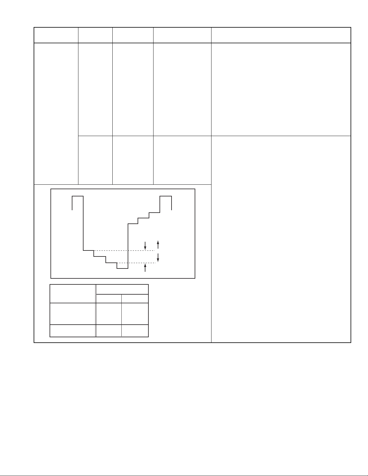
[3. DEF]
2. HOR. POSITION
(B)
[3. DEF]
4. VER. LIN.
5. VER. SCURVE
Top
Centre
(1) Receive a circle pattern signal.
(2) Select 3. DEF from the SERVICE MENU.
(3) Select < 2. HOR. POSITION >.
(4) Set the initial setting value of < 2. HOR. POSITION >.
(5) Adjust <2.HOR. POSITION> to be equal the width of
(A) and (B) as shown in Fig.2.
• When the vertical linearity has been deteriorated
remarkably, perform the following steps.
(1) Receive a crosshatch signal.
(2) Select 3. DEF from the SERVICE MENU.
(3) Select < 4. VER. LIN. >.
(4) Set the initial setting value of < 4. VER. LIN. >.
(5) Select < 5. VER. SCURVE >.
(6) Set the initial setting value of < 5. VER. SCURVE >.
(7) Adjust < 4. VER. LIN. > and < 5. VER. SCURVE >
so that the spaces of each line as shown in Fig.3 on
TOP, CENTRE and BOTTOM become uniform.
1-20 (No.YA370)
Bottom
Fig.3
4.8.5 VIDEO CIRCUIT
The setting (adjustment) using the REMOTE CONTROL UNIT is made on the basis of the initial setting values. The setting
values which adjust the screen to the optimum condition can be different from the initial setting values. Do not change the
initial setting values of the setting items not listed in "ADJUSTMENT PROCEDURE".
Item
WHITE
BALANCE
(LOW LIGHT)
Measuring
instrument
Signal
generator
Remote
control unit
Test point Adjustment part Description
[2.V/C]
1. CUT OFF (R)
1. CUT OFF (G)
1. CUT OFF (B)
SCREEN VR
[IN HVT]
(1) Receive a black and white signal (colour off).
(2) Select 2. V/C from the SERVICE MENU.
(3) Select < 1. CUT OFF >.
(4) Set the initial setting value of < 1. CUT OFF >.
(5) Press the [1] key to show the single horizontal line
on screen.
(6) Turn the SCREEN VR fully counter-clockwise, then
slowly turn it clockwise to where one of a red, blue or
KEY ASSIGNMENT OF REMOTE CONTROL UNIT
green colour is faintly visible.
(7) Adjust the two colors which did not appear until the
CUTOFF OFF
(H.LINE OFF)
CUTOFF ON
(H.LINE ON)
R. CUTOFF( )
R. CUTOFF( )
123
456
789
G.CUTOFF( )
B. CUTOFF( )
B. CUTOFF( )
G.CUTOFF( )
single horizontal line that is displayed becomes
white using the [4] to [9] keys.
(8) Turn the SCREEN VR to where the single horizontal
line glows faintly.
(9) Press the [2] key to turn off the single horizontal line.
(10) Press the [DISPLAY] key twice to return to the nor-
mal screen.
R G B
WHITE
BALANCE
(HIGH LIGHT)
Signal
generator
Remote
control unit
KEY ASSIGNMENT OF REMOTE CONTROL UNIT
R. DRIVE( )
SUB BRIGHT Remote
control unit
SUB
CONTRAST
Remote
control unit
123
456
789
R B
[2.V/C]
2. DRIVE (R)
2. DRIVE (B)
B. DRIVE( )
B. DRIVE( )R. DRIVE( )
[2. V/C]
3. BRIGHT
[2. V/C]
4. CONT.
(1) Receive a black and white signal (colour off).
(2) Select 2. V/C from the SERVICE MENU.
(3) Select < 2. DRIVE >.
(4) Set the initial setting value of < 2. DRIVE >.
(5) Adjust the screen until it becomes white using the
[4], [6], [7] and [9] keys.
(6) Press the [DISPLAY] key twice to return to the nom-
al screen.
(1) Receive any broadcast.
(2) Select 2. V/C from the SERVICE MENU.
(3) Select < 3. BRIGHT >.
(4) Set the initial setting value of < 3. BRIGHT >.
(5) If the brightness is not the best with the initial setting
value, make fine adjustment until you get the best
brightness.
(1) Receive any broadcast.
(2) Select 2. V/C from the SERVICE MENU.
(3) Select < 4. CONT >.
(4) Set the initial setting value of < 4. CONT >.
(5) If the contrast is not the best with the initial setting
value, make fine adjustment until you get the best
contrast.
(No.YA370)1-21
Item
Measuring
instrument
SUB COLOUR Remote
control unit
Signal
generator
Oscilloscope
Remote
control unit
W
MODEL
AV-1406FE
AV-14F16
AV-14146/N
AV-14149/N
AV-14FMG6/G
AV-14FMG6/S
Test point Adjustment part Description
TP-47G/R
TP-E
[CRT SOCKET
PWB]
R
M
Y
C
(A)
G
Voltage setting (A)
PAL SECAM NTSC3.58
+9.5V
+9.5V
+11V
+11V
[2. V/C]
5. COLOUR
(PAL / SECAM / NTSC)
[2. V/C]
5. COLOUR
(PAL / SECAM / NTSC)
B
0V
(+)
NTSC4.43
+12V
(VIDEO)
+11V
(RF)
+12V
(VIDEO)
+11V
(RF)
[Method of adjustment without measuring instrument]
PAL COLOUR
(1) Receive a PAL broadcast.
(2) Select 2. V/C from the SERVICE MENU.
(3) Select < 5. COLOUR >.
(4) Set the initial setting value of < 5. COLOUR >.
(5) If the colour is not the best with the initial setting
value, make fine adjustment until you get the best
colour.
SECAM COLOUR
(1) Receive a SECAM broadcast.
(2) Make fine adjustment of SECAM COLOUR as
previously.
NTSC 3.58 COLOUR
(1) Receive a NTSC 3.58MHz broadcast.
(2) Make similar fine adjustment of NTSC 3.58
COLOUR as previously.
NTSC 4.43 COLOUR
(1) When NTSC 3.58 adjustment completed, NTSC
4.43 will be automatically set at the respective
values.
[Method of adjustment using measuring instrument]
PAL COLOUR
(1) Receive a PAL full field colour bar signal (75%
white).
(2) Select 2. V/C from the SERVICE MENU.
(3) Select < 5. COLOUR >.
(4) Set the initial setting value of < 5. COLOUR >.
(5) Connect the oscilloscope between TP-47G/R and
TP-E.
(6) Adjust PAL COLOUR to bring the value of (A) in
the voltage table.
SECAM COLOUR
(1) Receive a SECAM full field colour bar signal (75%
white).
(2) Set the initial setting value of SECAM COLOUR .
(3) Adjust SECAM COLOUR to bring the value of (A)
in the voltage table.
NTSC 3.58 COLOUR
(1) Receive a NTSC 3.58 full field colour bar signal
(75% white).
(2) Set the initial setting value of NTSC 3.58
COLOUR.
(3) Adjust NTSC 3.58 COLOUR to bring the value of
(A) in the voltage table.
NTSC 4.43 COLOUR
(1) When NTSC 3.58 is set, NTSC 4.43 will be
automatically set at the respective values.
1-22 (No.YA370)
Item
Measuring
instrument
SUB TINT Signal
generator
Remote
control unit
Signal
generator
Oscilloscope
Remote
control unit
Test point Adjustment part Description
[2. V/C]
6. TINT
[Method of adjustment without measuring instrument]
NTSC 3.58 TINT
(1) Receive a NTSC 3.58 full field colour bar signal
(75% white).
(2) Select 2. V/C from the SERVICE MENU.
(3) Select < 6. TINT >.
(4) Set the initial setting value of < 6. TINT >.
(5) If you cannot get the best tint with the initial setting
value, make fine adjustment until you get the best
tint.
NTSC 4.43 TINT
(1) When NTSC 3.58 is set, NTSC 4.43 will be
automatically set at the respective values.
TP-47G/R
TP-E
[CRT SOCKET
PWB]
[2. V/C]
6. TINT
[Method of adjustment using measuring instrument]
NTSC 3.58 TINT
(1) Receive a NTSC 3.58 full field colour bar signal
(75% white).
(2) Select 2. V/C from the SERVICE MENU.
(3) Select < 6. TINT >.
(4) Set the initial setting value of < 6. TINT >.
(5) Connect the oscilloscope between TP-47G/R and
TP-E.
(6) Adjust NTSC 3.58 TINT to bring the value of (B)
B
R
M
NTSC 4.43 TINT
in the voltage table in the left.
(1) When NTSC 3.58 is set, NTSC 4.43 will be
automatically set at the respective values.
(-)
MODEL
AV-1406FE
AV-14F16
AV-14146/N
AV-14149/N
AV-14FMG6/G
AV-14FMG6/S
W
Y
NTSC3.58
(VIDEO)
C
G
Voltage setting (B)
NTSC4.43
+10V
+8.5V
(RF)
+10V
(VIDEO)
+8.5V
(RF)
0V
(B)
(+)
(No.YA370)1-23
Item
VSM PRESET
SECAM BLACK
OFFSET
Measuring
instrument
Signal
generator
Remote
control unit
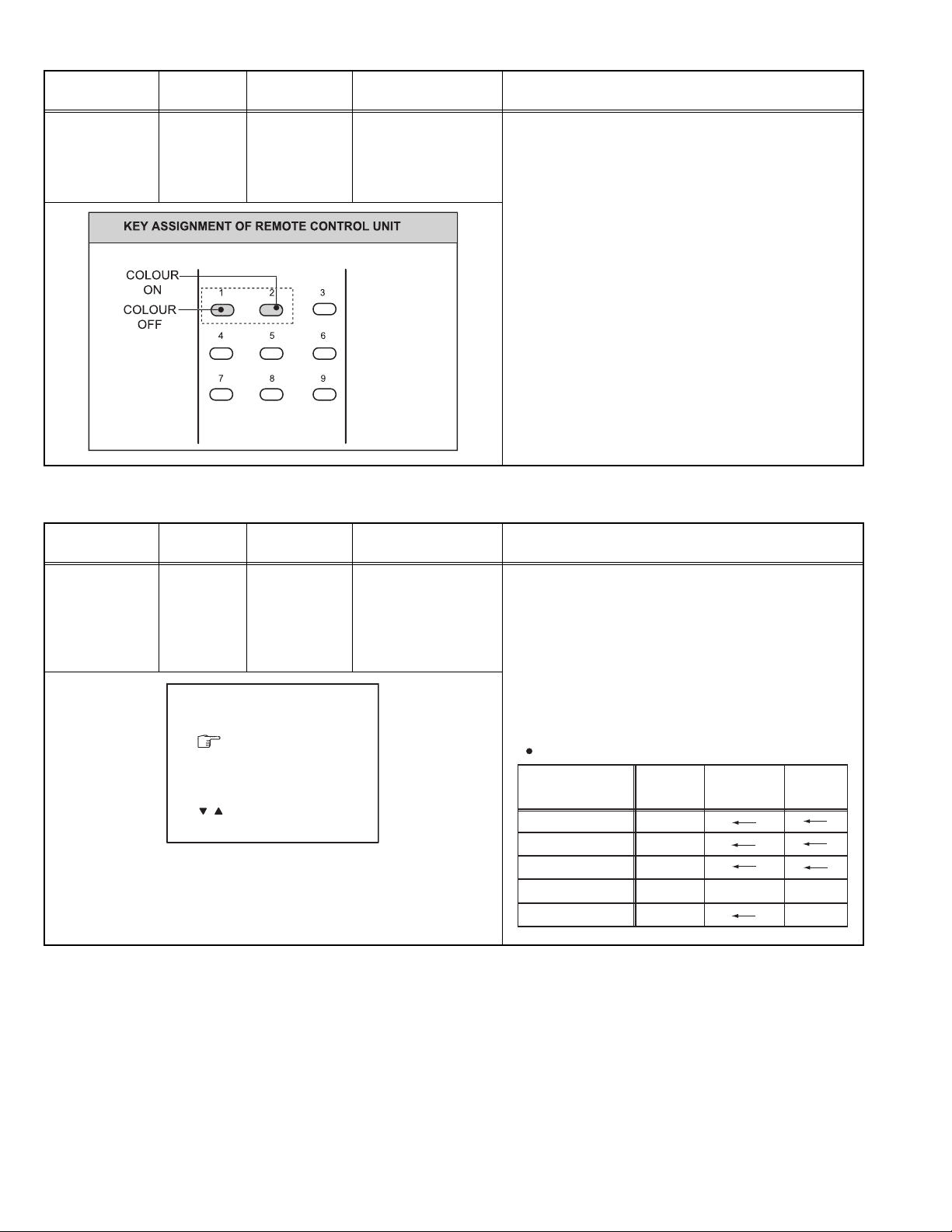
4.8.6 VSM PRESET SETTING
Test point Adjustment part Description
[2. V/C]
7. SECAM BL ADJUST
(1) Input a SECAM full field colour bar signal.
(2) Select 2. V/C from the SERVICE MENU.
(3) Select < 7. SECAM BL ADJUST >.
(4) Set the initial setting value of < 7. SECAM BL
ADJUST >.
(5) Switch the [1] key (colour OFF) and [2] key (colour
ON) and make sure that there is no colour on the
black and white screen.
(6) If the black and white screen is not best with the
initial setting value, make fine adjustment until you
get the best black and white screen.
(7) While watching the screen, adjust the value to be the
same colour between ON & OFF by [1] or [2] key.
(8) Press the [DISPLAY] key twice to return to the
normal screen.
Item
Measuring
instrument
VSM PRESET Remote
control unit
/ : SELECT
- / + : OPREATE DISP : EXIT
Test point Adjustment part Description
[4. VSM PRESET]
TINT
COLOUR
BRIGHT
CONT.
SHARP
(1) Select 4. VSM PRESET from the SERVICE MENU.
(2) Set the PICTURE MODE to BRIGHT.
(3) Select < TINT >.
(4) Set the initial setting value of < TINT > as shown in
the below table.
(5) Select < COLOUR > to < SHARP > in turn, and set
the values.
(6) Respectively select the "SOFT" and "STANDARD".
BRIGHT
TINT **
COLOUR **
BRIGHT **
CONT.
SHARP **
**
Make similar adjustment as same step as above.
VSM PRESET
Setting item
TINT
COLOUR
BRIGHT
CONT.
SHARP
BRIGHT
15
15
15
30
15
STANDARD SOFT
15
13
12
1-24 (No.YA370)
SECTION 5
TROUBLESHOOTING
This service manual does not describe TROUBLESHOOTING.

Victor Company of Japan, Limited
CRT Display Category 12, 3-chome, Moriya-cho, Kanagawa-ku, Yokohama-city, Kanagawa-prefecture, 221-8528, Japan
(No.YA370)
Printed in Japan
VPT

COLOUR TELEVISION
INSTRUCTIONS
Thank you for buying this JVC
colour television.
To make sure you understand how to
use your new TV, please read this
manual thoroughly before you begin.
AV-1406FE
AV-1406AE
Contents
Safety precautions 2
Preparation 3
1 Confirm which remote control you have
2 Inserting the batteries
3
Connecting the aerial and external devices
4 Connecting the power cord
5 SETUP TOUR
...................................
........................
..............................................
......
...
Basic operation 7
Remote control buttons and functions 8
PICTURE MODE button
COLOUR SYSTEM button
SOUND SYSTEM button
DISPLAY button
RETURN + button
CHANNEL SCAN button
MUTING button
OFF TIMER button
.................................
.............................
...............................
.............................................
..........................................
................................
.............................................
.........................................
Using the TV’s menus 10
Basic operation
ON TIMER
...........................................................
INPUT
...............................................................
VNR
AUTO SHUTOFF
CHILD LOCK
BLUE BACK
SETUP TOUR
LANGUAGE
AUTO CH PRESET
MANUAL CH PRESET
..............................................................
SKIP
Picture Adjustments
............................................
.....................................................
..........................................
.................................................
..................................................
...............................................
..................................................
.......................................
..................................
....................................
10
11
11
12
12
12
13
14
14
14
15
16
16
Using the buttons on the TV 17
Troubleshooting 19
Specifications 20
3
3
4
6
6
8
8
8
9
9
9
9
9
LCT1986-001A-H
1005TKH-NV-MT
© 2005 Victor Company of Japan, Limited
Safety precautions
WARNING
•To prevent fire or shock hazard, do not expose the TV to rain or moisture.
CAUTION
• Operate only from the power source indicated on the rear of the TV.
•Avoid damaging the power cord and mains plug. When you unplug the TV, pull it out by
the mains plug. Do not pull on the power cord.
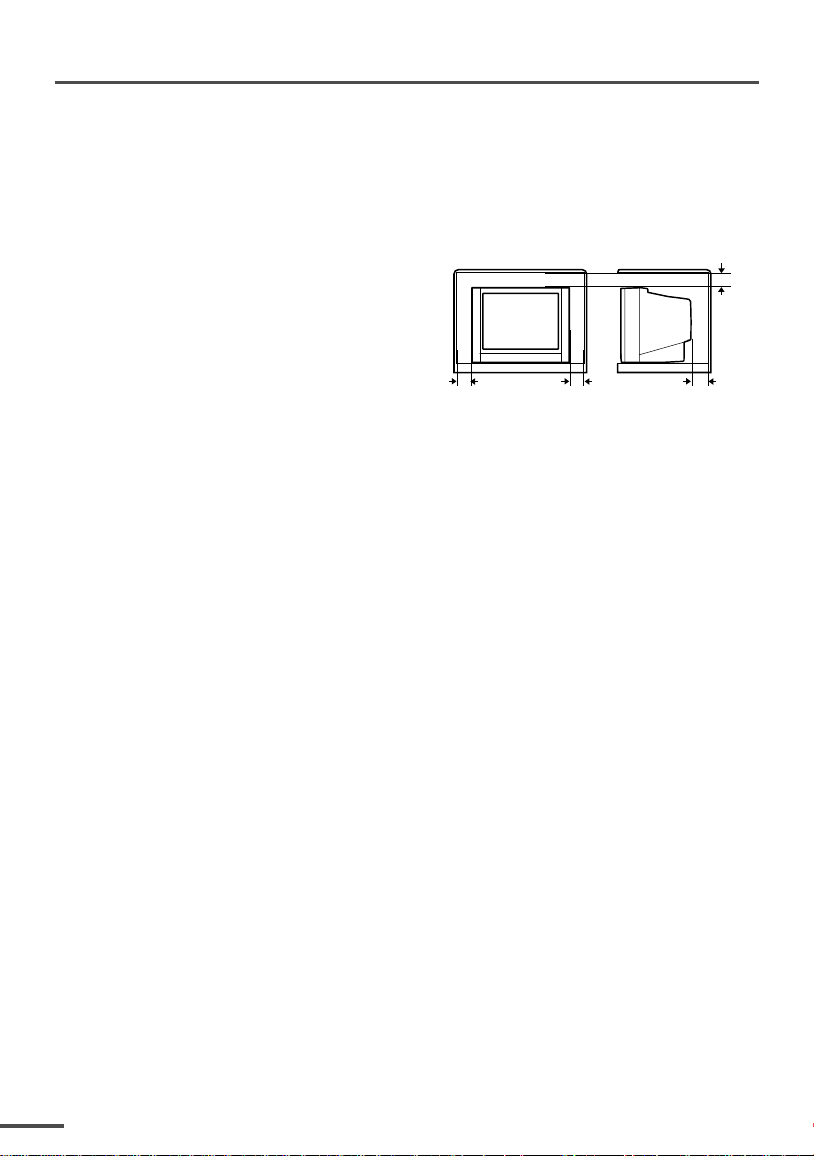
•Never block or cover the cabinet openings for
ventilation. Never install the TV where good
ventilation is unattainable. When installing
this TV, leave spaces for ventilation around
the TV more than the minimum distances
shown in the diagram.
• Do not allow objects or liquid into the
cabinet openings.
• In the event of a fault, unplug the TV and call a service technician. Do not attempt to
repair it by yourself or remove the rear cover.
• The surface of the TV screen is easily damaged. Be very careful with it when handling
the TV. Should the TV screen become soiled, wipe it with a soft dry cloth. Never rub it
forcefully. Never use any cleaner or detergent on it.
• When you don’t use this TV for a long period of time, be sure to unplug it.
10 cm 15 cm
10 cm
15 cm
2
Preparation
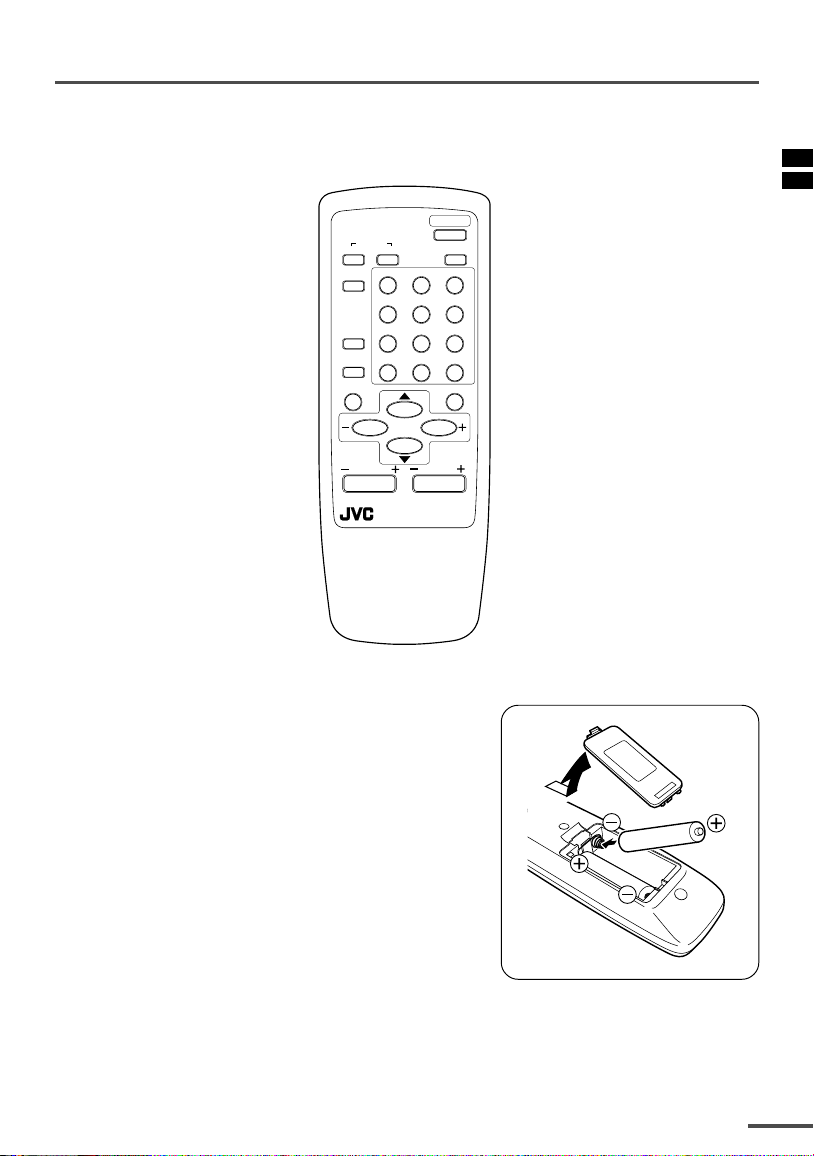
1 Confirm which remote control you have
RM-C360GY
POWER
COLOUR
TV/VIDEO
OFF
TIMER
CHANNEL
SCAN
DISPLAY
SYSTEM
SOUND
RETURN+
PICTURE
MODE
123
456
789
--
0-/
MUTING
MENU
CHANNEL
REMOTE CONTROL UNIT
2 Inserting the batteries
Correctly insert two batteries, observing the , and
. polarities and inserting the . end first.
CAUTION:
Follow the cautions printed on the batteries.
Notes:
• Use AA/R6/UM-3 dry cell batteries.
• If the remote control does not work properly, fit new
batteries.
The supplied batteries are for testing, not regular use.
VOLUME
3
Preparation
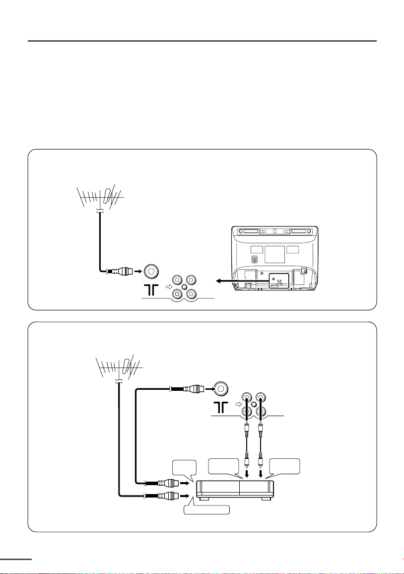
3 Connecting the aerial and external devices
•For further details, refer to the manuals provided with the devices you are connecting.
• Connecting cables are not supplied.
• The front and rear AUDIO/VIDEO input jacks are directly connected so that input to either jack
is output through both. You cannot provide input to both the front and rear jacks at the same
time. Disconnect one input, or use one of the jacks as an output jack only (for monitoring or
recording).
■ Connecting the aerial and VCR
Connecting the aerial
VHF/UHF outdoor aerial
VIDEO
AUDIO
IN
OUT
• Illustration of AV-1406FE.
Connecting the aerial and VCR
VHF/UHF outdoor aerial
4
1
To RF
output
To aerial input
2
To video
output
VIDEO
AUDIO
IN
OUT
3
To audio
output
VCR
• Illustration of AV-1406FE.
 Loading...