


 Loading...
ENGLISH
DP-2100/IP-420
INSTRUCTION MANUAL
* "CompactFlash(TM)" is the registered trademark of SanDisk Corporation, U.S.A.
CONTENTS
1. SPECIFICATIONS .................................................................................... |
1 |
1-1 Specifications of the machine head....................................................................... |
1 |
1-2 Specifications of the control box........................................................................... |
1 |
2. CONFIGURATION..................................................................................... |
2 |
2-1 Sewing machine main unit...................................................................................... |
2 |
3. INSTALLATION ........................................................................................ |
3 |
3-1 Caution at the time of set-up.................................................................................. |
3 |
3-2 Assembling the pedal section of the stand.......................................................... |
4 |
3-3 Assembling the table.............................................................................................. |
5 |
3-4 Connecting the power cable.................................................................................. |
6 |
3-5 Installing the sewing machine main unit............................................................... |
6 |
3-6 Installing the cover.................................................................................................. |
7 |
3-7 Installing the stopper for tilt prevention................................................................ |
7 |
3-8 Installing the operation panel................................................................................ |
7 |
3-9 Connecting the cords.............................................................................................. |
8 |
3-10 Installing the throat plate auxiliary plate............................................................. |
9 |
3-11 Installing the thread guide rod.............................................................................. |
9 |
3-12 Installing the thread stand.................................................................................. |
10 |
3-13 Assembling the table for work (WORK TOP TABLE)........................................ |
10 |
4. PREPARATION BEFORE OPERATION ................................................ |
11 |
4-1 Attaching the needle............................................................................................. |
11 |
4-2 Threading the needle-thread................................................................................ |
11 |
4-3 Winding the bobbin thread................................................................................... |
12 |
4-4 Setting the bobbin into the bobbin case ............................................................ |
12 |
4-5 Attaching and removing the bobbin case........................................................... |
13 |
4-6 Adjusting the thread tension................................................................................ |
13 |
4-7 Adjusting the thread take-up spring.................................................................... |
13 |
4-8 Adjusting the stitch guide.................................................................................... |
13 |
5. HOW TO USE THE OPERATION PANEL............................................... |
14 |
5-1. PREFACE............................................................................................................... |
14 |
5-2.BASIC OPERATION OF THE OPERATION PANEL (IP-420) ............................... |
18 |
(1) Configuration of IP-420 .................................................................................................................... |
18 |
(2) Buttons used in common.................................................................................................................. |
19 |
6. OPERATION OF THE SEWING MACHINE (SEMI-AUTOMATIC BASIC VOLUME).................... |
20 |
6-1 Data input screen.................................................................................................. |
20 |
6-2 Sewing screen....................................................................................................... |
22 |
6-3 Details data input screen...................................................................................... |
23 |
6-4 Feed amount.......................................................................................................... |
25 |
6-5 Basic operation of the sewing machine.............................................................. |
26 |
(1) Prepare the materials....................................................................................................................... |
26 |
(2) Turn ON the power switch................................................................................................................ |
26 |
(3) Calling the pattern <Pattern No. selection>...................................................................................... |
26 |
(4) |
Select left/right alternate sewing. <Left/right alternate sewing selection>........................................ |
27 |
(5) |
Perform sewing................................................................................................................................. |
28 |
6-6 Basic change of the set value.............................................................................. |
30 |
|
(1) |
Changing the sewing speed <Max. sewing speed setting>.............................................................. |
30 |
(2) |
Changing the pitch <Pitch setting>................................................................................................... |
30 |
(3) |
Changing the needle thread tension <Needle thread tension setting>............................................. |
31 |
(4) |
Changing the shirring amount <Shirring amount setting>................................................................ |
32 |
(5) |
Changing the shirring amount of auxiliary feed <Auxiliary feed shirring amount setting>.............................. |
32 |
6-7 Creating the pattern <Pattern creation>.............................................................. |
33 |
|
6-8 Deleting the pattern <Pattern deletion>.............................................................. |
34 |
|
7. OPERATION OF THE SEWING MACHINE (SEMI-AUTOMATIC APPLICATION VOLUME)................... |
36 |
|
7-1 Correcting the pattern........................................................................................... |
36 |
|
(1) |
Changing the needle thread tension of specified step <Compensation thread tension setting>................................ |
36 |
(2) |
Changing the pitch of specified step <Compensation pitch setting>................................................ |
37 |
(3) |
Increasing/decreasing the shirring amount of all steps <Shirring amount increase/decrease |
|
|
setting>............................................................................................................................................. |
38 |
(4) |
Increasing/decreasing the shirring amount immediately after changeover of step<Compensation |
|
|
shirring amount setting>................................................................................................................... |
39 |
(5) Adding the step <Step addition>....................................................................................................... |
40 |
|
(6) |
Deleting the step <Step deletion>.................................................................................................... |
42 |
(7) |
Changing the start position of program <Start position change>..................................................... |
44 |
(8) |
Mirroring the program of one sleeve and creating the program of the other sleeve <Mirroring |
|
|
function> .......................................................................................................................................... |
46 |
(9) |
Changing the top notch position of program <Top notch position change>...................................... |
47 |
(10) Naming the pattern <Data name setting>....................................................................................... |
49 |
|
7-2 Copying the pattern <Pattern copy>.................................................................... |
50 |
|
(1) |
Pattern copy in semi-automatic mode <Copy to semi-automatic>................................................... |
50 |
(2) |
Pattern copying from semi-automatic to fully-automatic <Copy to fully-automatic>......................... |
51 |
7-3 Creating the new pattern <New pattern creation>............................................. |
52 |
|
7-4 Using the other functions..................................................................................... |
54 |
|
(1) |
Directly calling the pattern from the sewing screen <Direct pattern selection>................................ |
54 |
(2) Adjust the STEP SELECTION button to the shape of sleeve <Measure function>.......................... |
54 |
|
8. OPERATION OF THE SEWING MACHINE (FULLY-AUTOMATIC BASIC |
||
VOLUME)................................................................................................ |
55 |
|
8-1 Data input screen.................................................................................................. |
55 |
|
8-2 Sewing screen....................................................................................................... |
57 |
|
8-3 Detailed data input screen.................................................................................... |
58 |
|
8-4 Feed amount.......................................................................................................... |
60 |
|
8-5 Basic operation of the sewing machine.............................................................. |
61 |
|
(1) |
Prepare the materials....................................................................................................................... |
61 |
(2) Turn the power ON........................................................................................................................... |
61 |
|
(3) |
Calling the pattern <Pattern No. selection>...................................................................................... |
61 |
(4) |
Selecting left/right alternate sewing <Left/right alternate sewing selection>.................................... |
62 |
(5) |
Performing sewing............................................................................................................................ |
62 |
8-6 Changing the basic set value .............................................................................. |
64 |
|
(1) |
Changing the sewing machine speed <Max. sewing speed setting>............................................... |
64 |
(2) |
Changing the pitch <Pitch setting>................................................................................................... |
65 |
(3) |
Changing the needle thread tension <Needle thread tension setting>............................................. |
65 |
(4) |
Changing the shirring amount <Shirring amount setting>................................................................ |
66 |
(5) |
Changing the shirring amount of auxiliary feed <Auxiliary feed shirring amount setting>................................. |
66 |
8-7 Creating the pattern <Pattern creation>.............................................................. |
67 |
|
8-8 Deleting the pattern <Pattern deletion>.............................................................. |
69 |
|
|
ii |
|
9. OPERATION OF THE SEWING MACHINE (FULLY-AUTOMATIC |
|
|
APPLICATION VOLUME)....................................................................... |
71 |
|
9-1 Correcting the pattern........................................................................................... |
71 |
|
(1) |
Changing the length of specified step <Length between steps setting>.......................................... |
71 |
(2) |
Changing the needle thread tension of specified step <Compensation thread tension setting>...... |
72 |
(3) |
Changing the pitch of specified step <Compensation pitch setting>................................................ |
73 |
(4) |
Increasing/decreasing the shirring amount of all steps <Shirring amount increase/decrease |
|
|
setting>............................................................................................................................................. |
75 |
(5) |
Increasing/decreasing the shirring amount immediately after changeover of step <Compensation |
|
|
shirring amount setting>................................................................................................................... |
76 |
(6) Adding the step <Step addition>....................................................................................................... |
77 |
|
(7) |
Deleting the step <Step deletion>.................................................................................................... |
79 |
(8) |
Changing gent's/ladies' wear classification <Gent's/ladies' selection>............................................. |
81 |
(9) |
Changing the size <Size change>.................................................................................................... |
82 |
(10) Setting the offset value of grading <Grading value setting>........................................................... |
83 |
|
(11) Changing the start position of program <Start position change>.................................................... |
84 |
|
(12) Mirroring the program of one sleeve and creating the program of the other one <Mirroring |
|
|
|
function>........................................................................................................................................... |
85 |
(13) Changing the top notch position of program <Top notch position change>.................................... |
87 |
|
(14) Naming the pattern <Data name setting>....................................................................................... |
88 |
|
9-2 Copying the pattern <Pattern copy>.................................................................... |
89 |
|
(1) |
Pattern copy in the fully-automatic <Copy to fully-automatic>.......................................................... |
89 |
(2) |
Pattern copy from fully-automatic to semi-automatic <Copy to semi-automatic>............................. |
91 |
9-3 Creating a new pattern <New pattern creation>................................................. |
92 |
|
9-4 Using other functions........................................................................................... |
94 |
|
(1) |
Directly calling the pattern from sewing screen <Direct pattern selection>...................................... |
94 |
(2) |
Re-registering the length between steps <Measure function>......................................................... |
95 |
10. OPERATION OF THE SEWING MACHINE (MANUAL BASIC |
|
|
VOLUME)................................................................................................ |
96 |
|
10-1 Data input screen................................................................................................. |
96 |
|
10-2 Sewing screen .................................................................................................... |
97 |
|
10-3 Details data input screen.................................................................................... |
98 |
|
10-4 Basic operation of the sewing machine............................................................ |
99 |
|
(1) |
Prepare the materials....................................................................................................................... |
99 |
(2) Turn the power ON........................................................................................................................... |
99 |
|
(3) |
Perform sewing................................................................................................................................. |
99 |
10-5 Changing the basic set value........................................................................... |
100 |
|
(1) |
Changing the sewing speed <Max. sewing speed setting>............................................................ |
100 |
(2) |
Changing the pitch <Pitch setting>................................................................................................. |
101 |
(3) |
Changing the needle thread tension <Needle thread tension setting>........................................... |
102 |
11. OPERATION OF THE SEWING MACHINE (MANUAL APPLICATION |
||
VOLUME).............................................................................................. |
103 |
|
11-1 Changing the detailed set value....................................................................... |
103 |
|
(1) |
Changing the operating mode of auxiliary pedal <Auxiliary pedal operation selection>......................... |
103 |
(2) |
Changing the auxiliary feed operating mode <Auxiliary feed mode selection>.............................. |
104 |
(3) |
Setting the auxiliary feed interlock mode <Auxiliary feed interlock mode setting>......................... |
106 |
(4) |
Setting the range of shirring amount <Shirring amount range setting>.......................................... |
108 |
(5) |
Setting the compensation thread tension <Compensation thread tension setting>....................... |
109 |
12. USING COUNTER............................................................................... |
110 |
|
12-1 Setting procedure of the counter..................................................................... |
110 |
|
12-2 Count-up releasing procedure......................................................................... |
113 |
|
iii
13. REGISTERING AND THE PATTERN TO DIRECT BUTTON AND |
|
|
RELEASING THE PATTERN FROM DIRECT BUTTON ..................... |
113 |
|
13-1 How to register................................................................................................... |
113 |
|
13-2 How to release................................................................................................... |
114 |
|
13-3 Register state at the time of your purchase.................................................... |
115 |
|
14. CHANGING SEWING MODE.............................................................. |
115 |
|
15. CHANGING MEMORY SWITCH DATA............................................... |
116 |
|
15-1 Changing procedure of memory switch data.................................................. |
116 |
|
15-2 Memory switch data list.................................................................................... |
117 |
|
15-3 Explanation of compensation thread tension................................................. |
124 |
|
(1) |
Explanation of compensation tension manual (numerical value) .................................................. |
124 |
(2) |
Explanation of compensation tension manual (level)..................................................................... |
126 |
(3) |
Explanation of compensation thread tension automatic................................................................. |
129 |
15-4 Explanation of the shirring smoothing function............................................. |
131 |
|
(1) |
Explanation of the motion of shirring smoothing function............................................................... |
131 |
(2) |
Setting of the shirring smoothing function...................................................................................... |
132 |
15-5 Explanation of the size class............................................................................ |
133 |
|
(1) |
Explanation of the size class.......................................................................................................... |
133 |
(2) |
Size development........................................................................................................................... |
135 |
16. ERROR CODE LIST............................................................................ |
136 |
|
17. USING COMMUNICATION FUNCTION.............................................. |
140 |
|
17-1 Handling possible data...................................................................................... |
140 |
|
17-2 Performing communication by using the media............................................. |
140 |
|
17-3 Performing communication by using USB...................................................... |
140 |
|
17-4 Take-in of the data............................................................................................. |
141 |
|
18. INFORMATION FUNCTION................................................................ |
144 |
|
18-1 Observing the maintenance and inspection information............................... |
144 |
|
18-2 Inputting the inspection time............................................................................ |
146 |
|
18-3 Releasing procedure of the warning................................................................ |
147 |
|
18-4 Observing the production control information............................................... |
148 |
|
(1) |
When displaying from the information screen................................................................................ |
148 |
(2) |
When displaying from the sewing screen....................................................................................... |
149 |
18-5 Performing setting of the production control information............................ |
150 |
|
18-6 Observing the working measurement information........................................ |
153 |
|
19. PERFORMING FORMATTING OF THE MEDIA................................. |
156 |
|
20. TRIAL SEWING FUNCTION............................................................... |
157 |
|
20-1 Performing trial sewing..................................................................................... |
157 |
|
21. PERFORMING KEY LOCK................................................................. |
159 |
|
22. DISPLAYING VERSION INFORMATION............................................ |
161 |
|
23. USING CHECK PROGRAM................................................................ |
162 |
|
23-1 Displaying the check program screen............................................................. |
162 |
|
23-2 Performing the auxiliary pedal setting............................................................ |
163 |
|
23-3 Performing checking of A/D value of auxiliary pedal.................................... |
164 |
|
iv
23-4 Performing LCD check...................................................................................... |
164 |
23-5 Performing touch panel compensation........................................................... |
165 |
23-6 Performing the input signal check.................................................................. |
167 |
23-7 Performing the output signal check................................................................ |
169 |
24. COMMUNICATION SCREEN OF MAINTENANCE PERSONNEL |
|
LEVEL................................................................................................... |
171 |
24-1 Data which are possible to be handled........................................................... |
171 |
24-2 Displaying maintenance personnel level........................................................ |
172 |
25. INFORMATION SCREEN OF THE MAINTENANCE PERSONNEL LEVEL.............. |
173 |
25-1 Display of error record...................................................................................... |
173 |
25-2 Display of the cumulative working information.............................................. |
174 |
26. MAINTENANCE................................................................................... |
175 |
26-1 Replacing procedure of feed belt..................................................................... |
175 |
(1) Replacing the top feed belt............................................................................................................. |
175 |
(2) Replacing the bottom feed belt....................................................................................................... |
176 |
(3) Replacing the bottom feed roller..................................................................................................... |
176 |
26-2 Changing the amount of alternate vertical movement of walkingfoot and |
|
presser foot ........................................................................................................ |
177 |
(1) When making equal the amount of alternate vertical movement of walking foot and presser foot |
|
(When making the amount equal to 1.5 mm)................................................................................. |
178 |
(2) When making 2.5 mm the amount of alternate vertical movement ............................................... |
178 |
26-3 Adjusting the height of the walking foot and the presser foot...................... |
179 |
(1) Adjusting the height of walking foot................................................................................................ |
179 |
(2) Adjusting the height of presser foot................................................................................................ |
179 |
26-4 Adjusting the needle and the hook.................................................................. |
180 |
(1) Adjusting the height of needle bar................................................................................................................... |
180 |
(2) Adjusting the hook.......................................................................................................................... |
180 |
26-5 Adjusting the thread trimmer........................................................................... |
181 |
(1) Adjusting the thread trimmer cam timing........................................................................................ |
181 |
(2) Adjusting the initial position of the moving knife............................................................................. |
181 |
(3) Adjusting the initial position of the thread trimmer solenoid............................................................ |
182 |
(4) Adjusting the position of the moving knife and the counter knife.................................................... |
183 |
26-6 Greasing parts................................................................................................... |
183 |
27. OTHERS.............................................................................................. |
184 |
27-1 Troubles in sewing and the corrective measures........................................... |
184 |
28. DRAWING OF THE TABLE................................................................. |
185 |
28-1 Slant table........................................................................................................... |
185 |
28-2 Work top table.................................................................................................... |
186 |
28-3 Edge stopper A ................................................................................................. |
187 |
28-4 Edge stopper B ................................................................................................. |
188 |

1. SPECIFICATIONS
1-1 Specifications of the machine head
Sewing speed |
Max. 3,500 sti/min (*1) |
||
Feed system |
Intermittent belt feed by direct drive of stepping motor |
||
Stitch length |
Both top and bottom 1.5 to 6 mm |
||
Stitch length adjustment system |
Panel input |
||
Stitch length adjustment minimum resolution |
0.1 mm |
||
Needle bar stroke |
30.7 mm |
||
Needle |
DPX17 #10 to #14 |
||
Hook |
Full-rotary non-lubricated horizontal-axis hook |
||
Presser foot lift |
By hand lifter : 5.5 mm, by auto-lifter : 10 mm |
||
Amount of alternate vertical movement of |
Max. 3.5 mm |
||
presser foot/walking foot |
|||
|
|
||
Adjustment of amount of alternate vertical |
Slot stop position adjustment |
||
movement of presser/walking foot |
|||
|
|
||
Lubrication |
Non-lubrication |
||
Number of programs that can be inputted |
99 programs |
||
Number of steps that can be inputted (per |
30 steps |
||
program) |
|||
|
|
||
Data mirroring |
Provided |
||
Right/left alternate sewing |
Possible |
||
Data record |
Main body, Media |
||
Noise |
- |
Equivalent continuous emission sound pressure level (LpA) at the |
|
|
|
workstation : |
|
|
|
A-weighted value of 84.5 dB; (Includes KpA = 2.5 dB); according to |
|
|
|
ISO 10821- C.6.2 -ISO 11204 GR2 at 3,400 sti/min for the sewing |
|
|
- |
cycle, 6.7s ON and 7.5s OFF (Pattern : check_mode4). |
|
|
Sound power level (LWA) ; |
||
|
|
A-weighted value of 89.5 dB; (Includes KWA = 2.5 dB); according to |
|
|
|
ISO 10821- C.6.3 -ISO 3744 GR2 at 3,400 sti/min for the sewing |
|
|
|
cycle, 6.7s ON and 7.5s OFF (Pattern : check_mode4). |
|
|
*1. The maximum sewing speed is limited in accordance with the amount of alternate vertical movement |
||||||||||||
|
of presser foot and walking foot, and stitch length. |
|
|
|
|
||||||||
|
Limitation by the amount of alternate vertical movement of presser and walking foot |
||||||||||||
|
|
|
|
|
|
|
|
|
|
|
|
||
|
|
Max. sewing speed (sti/min) |
|
Amount of vertical movement of |
|
Amount of vertical movement |
|
||||||
|
|
|
|
|
|
walking foot (mm) |
|
of presser foot (mm) |
|
||||
|
|
|
|
|
|
|
|
|
|
||||
|
|
|
3,500 |
|
|
|
|
|
Less than 0.3 |
(2.7) |
|
||
|
|
|
2,600 |
|
|
|
Not less than 0.3 to 1.5 |
(1.5) |
|
||||
|
|
|
2,000 |
|
|
|
Not less than 1.5 to 2.5 |
(2.5) |
|
||||
|
|
|
1,600 |
|
|
|
Not less than 2.5 to 3.5 |
(3.5) |
|
||||
|
Limitation by stitch length |
|
|
|
|
|
|
|
|
|
|
||
|
|
|
|
|
|
|
|
|
|
|
|
||
|
|
Max. sewing speed (sti/min) |
|
|
|
Stitch length (mm) |
|
|
|
|
|||
|
|
|
3,500 |
|
|
|
|
|
1.5 to 4.0 |
|
|
|
|
|
|
|
2,500 |
|
|
|
|
|
4.1 to 6.0 |
|
|
|
|
1-2 Specifications of the control box |
|
|
|
|
|||||||||
|
|
|
|
|
|
||||||||
Power voltage |
3-phase 200V/220V/240V |
|
Single phase 220V/230V/240V |
||||||||||
Frequency |
|
|
|
|
50Hz/60Hz |
|
|
|
|
||||
Rated current |
2.6A/2.4A/2.2A |
|
|
2.8A/2.6A/2.5A |
|
|
|
|
|||||
Operating tempera- |
|
0 to 40˚C, Less than 90% |
|
|
|
|
|||||||
ture/humidity |
|
|
|
|
|
||||||||
|
|
|
|
|
|
|
|
|
|
|
|||
– –
2. CONFIGURATION
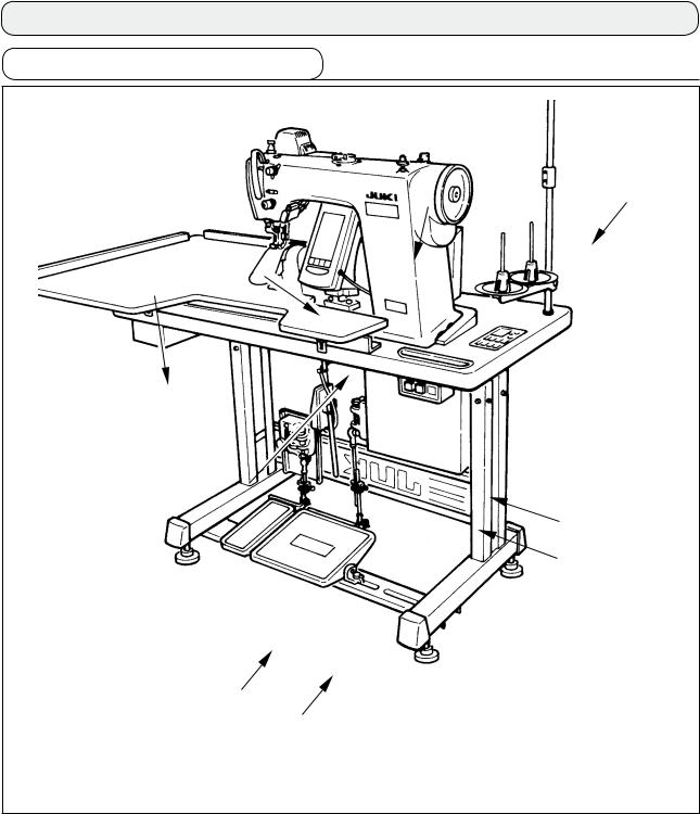
2-1 Sewing machine main unit
1 |
8 |
9
4
2
 5
5  3
3
7
6
1 Sewing machine head
2 Operation panel
3 Control box
4 Auxiliary table (WORK TOP TABLE)
5 Power switch
6 Main pedal
7 Auxiliary pedal
8 Thread stand
9 Shirring release switch
––

3. INSTALLATION
3-1 Caution at the time of set-up
1) Transporting procedure of the sewing machine
Hold and transport the sewing machine with two persons as shown in the illustration.
Do not hold the handwheel.
2) Caution when placing the sewing machine
Do not put protruding articles such as the screwdriver and the like at the location where the sewing machine is placed.
3) Removing the air vent cap
Be sure to remove the red rubber cap as shown in the illustration before operating the sewing machine. When transporting the machine head only, attach this rubber cap to the machine head.
––
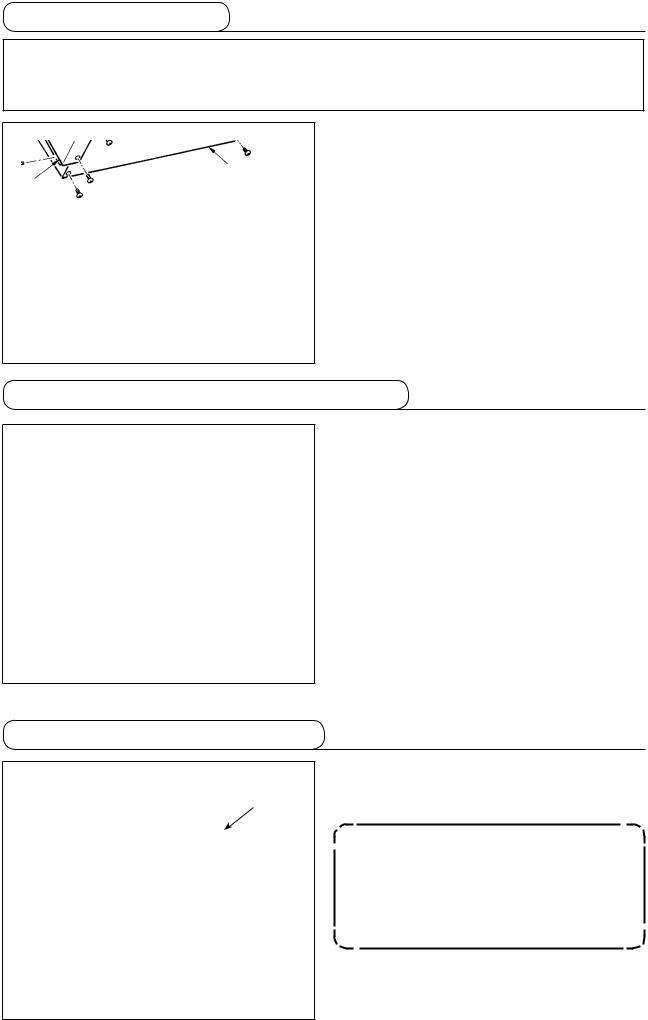
3-2 Assembling the pedal section of the stand
83
8
2
7
4
5
|
|
7 |
|
6 |
2 |
1 |
|
|
|
|
|
|
|
1 |
1)Assemble the lower strut to the stand using square nut 7 (wide width).
2)Put bush 4 to the pedal 8 and pass it through shaft 5 together with shaft bearing plate 3. Then fix with pedal shaft bearing 2.
3)Fix pedal shaft bearing 2 using square nut 1 (narrow width).
4)Assemble the whole pedal after fully drawing it up in the left direction in the illustration.
[When using with 1-pedal]
There is the short shaft for 1-pedal in the accessories. Remove the small pedal and shaft bearing plate 3 and replace the shaft with the shaft for 1-pedal. Then the machine can be used even with 1-pedal.
––
3-3 Assembling the table
7 |
5 |
7 |
|
4 |
|||
|
|
8 |
|
5 |
|
|
|
|
6 |
6 |
|
|
1
8
!5 2
!0
93
!1 !4
9 !2
!3
1) Fix hinge seats 5 and machine head supporting rubbers 6 on table 1 with the nails. (Use 2 pcs. each of nail for fixing hinge seats 5 and 1 pc. each of nail for fixing machine head supporting rubbers.)
2) Attach felts 7 to machine head supporting rubbers 6. 3) Attach machine head supporting rubbers 8 to table 1.
4) Fix stopper plate 9 to the rear side of table 1.
Caution) Be sure to install stopper plate 9 before installing control box 2.
5)Fix control box 2 and power switch 3, and fix the power cable with the staples.
6)Fix power switch 3 under the machine table witch wood screw !4. Fix the cable with staple !5supplied with the machine as accessories in accordance witch the forms of use.
7)Temporarily fix the side strut so that it is put between auxiliary pedal sensor !0and sensor plate !1.
8)Connect pedal (large) and pedal sensor !2with connecting rod (long). Adjust the inclination of connecting rod at the position of adjusting plate !3.
9)Connect pedal (small) and auxiliary pedal sensor !0with connecting rod (short). Adjust the inclination of connecting rod at the position of auxiliary pedal sensor and securely tighten the screw.
10)Install head supporting rod 4 on table 1.
––

3-4 Connecting the power cable
Connect the cable in accordance with the specifications.
• Connection of 3-phase 200V/220V/240V
Red |
Red |
|
Table |
|
|
Control box |
Green/Yellow |
|
|
Plug |
|
Green/Yellow |
|
|
|
|
|
White Black White |
Black |
|
|
Power switch |
Power source cord |
• Connection of single phase 220V/230V/240V
Light blue Light blue
Table
Green/Yellow
Control box
Plug
Green/Yellow
Brown Brown Power switch
Power source cord
Red |
|
|
|
|
AC200 V |
|
|
|
|
||
|
|
|
|
|
|
White |
|
|
AC220 V |
||
|
|
||||
Black |
|
|
|
AC240 V |
|
|
|
|
|||
Green/YellowGND
Brown |
|
|
|
|
AC220 V |
Light blue |
|
|
|
AC230 V |
|
|
|
|
|||
|
|
|
AC240 V |
||
|
|
||||
Green/YellowGND

 Never use the machine with the wrong power specifications.
3-5 Installing the sewing machine main unit
WARNING :
To prevent possible accidents caused by the fall of the sewing machine, perform the work by two persons or more when the machine is moved.
Insert hinges 1 into the holes in the frame and place the machine head on the table.
1
1
––
3-6 Installing the cover
WARNING :
When tilting/raising the sewing machine head, perform the work so as not to allow your fingers to be caught in the machine. In addition, to avoid possible accidents caused by abrupt start of the machine, turn OFF the power to the machine before starting the work.
Slowly tilt the machine head and install bottom cover 1 and bottom feed cover 2.
1
2
3-7 Installing the stopper for tilt prevention
Install stopper plate A 1 and stopper plate B 2 for tilt prevention.
1
2
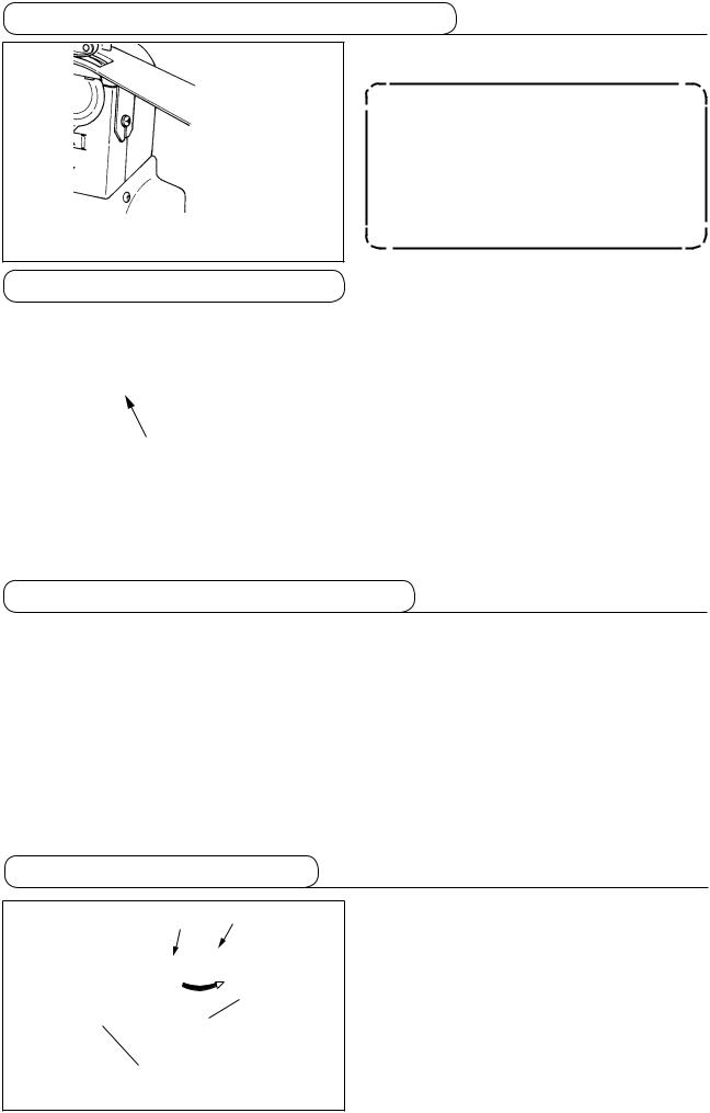
3-8 Installing the operation panel
AFix panel installing plate 2 to the base on the frame. Install operation panel 1 with a magnet and
1pass the cable through the hole in the table.
When the panel is installed in the state that it is excessively tilted in the direction A, the work table comes in contact with the panel and the panel
 2 may be damaged. Install the panel so that it is not excessively tilted.
––

3-9 Connecting the cords
|
Ground wire |
Sewing machine head |
||
|
CN38 |
|||
CN21 |
|
|
||
CN25 |
|
|
||
CN26 |
|
|
||
CN56 |
|
|
||
CN57 |
|
|
||
CN53 |
|
|
||
CN52 |
|
Knee SW |
||
CN51 |
Auxiliary pedal |
|||
|
|
|||
CN55 |
|
|
||
|
|
|
||
CN62 |
|
|
|
|
CN54 |
|
|
Operation panel |
|
|
|
|
||
CN34 |
|
|
|
|
|
CN26 |
CN25 |
|
|
Cord inserting |
|
|
|
|
port |
|
|
|
|
PWR circuit |
|
|
|
CN21 |
board |
|
|
|
|
CN38 |
|
|
|
CN34 |
|
|
|
|
|
CN55 |
|
|
|
|
CN54 |
|
|
|
|
CN53 |
|
|
|
|
CN52 |
CN56 CN57 |
CN62 |
||
CN51 |
||||
MAIN circuit board
Sticker (small)
Terminal |
No. of poles |
Name of cable |
CN38 |
White 4 poles |
Power cable of main motor |
CN21 |
White 9 poles |
Encoder cable of main motor |
CN25 |
Red 2 poles |
Top feed fan cord |
CN26 |
Red 2 poles |
Bottom feed fan cord |
CN56 |
White 10 poles |
Feed motor cord |
CN57 |
White 6 poles |
Auxiliary feed motor cord |
CN53 |
White 6 poles |
Head relay cord 1 |
CN52 |
White 4 poles |
Head relay cord 2 |
CN51 |
White 2 poles |
Presser lifter cord |
CN55 |
10 poles |
DATA p.c.b. cord |
CN62 |
Yellow 4 poles |
|
CN54 |
Red 4 poles |
|
CN34 |
26 poles |
|
1)Remove the auxiliary pedal cord and insert the cord into the control box from the cord inserting port. Pass the auxiliary pedal cord through the rear side of the auxiliary pedal and insert it into the control box from hole A located on the lower side of the pedal sensor.
2)Fix the auxiliary pedal cord with the sticker (small) so that the cord does not move.
3)Connect CN38, 21, 25, and 26 to PWR p.c.b. CN25 and 26 can be connected to either one. Connect others to MAIN p.c.b.
A
––

Cord clamp A 
4)Fix the cords connected to MAIN p.c.b. with cord clamp A.
Handling the cords
1)When fixing the cords, connect them with the sewing machine tilted, and bundle with clip band 1.
2)When the machine head
is returned to its home |
2 |
|
|
||
position, fix the cords |
|
|
with cord fixing plate 2 |
|
|
in the state that there is |
1 |
|
the slack in the cords. |
||
|
Caution : When tilting the sewing machine, make sure that the head support bar is attached to the table.
3-10 Installing the throat plate auxiliary plate
|
|
Loosen two screws 2, insert throat plate auxiliary |
|
|
|
|
|
plate 1 and fix it. |
2 |
1 |
Adjust the height so that the top sur- |
|
face of throat plate auxiliary plate |
|
|
|
|
|
|
aligns with that of the throat plate. |
|
|
If the height is not proper, material |
|
|
flops and the feed amount is not set- |
2 |
|
tled. |
|
|
|
3-11 Installing the thread guide rod
Securely insert thread guide rod 1 so that two side holes of it faces the front in the direction of the op-
1erator.
––

3-12 Installing the thread stand
1) Assemble the thread stand unit and set it to the hole located on the upper right side of the table.
2) Tighten lock nut 1 so that the thread stand unit does not move.
3) When ceiling wiring is possible, pass the power cable through the inside of thread stand rod 2.
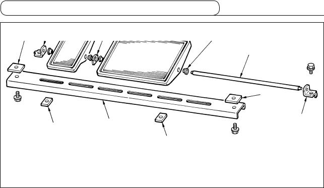
3-13 Assembling the table for work (WORK TOP TABLE)
8
3
9 |
1 |
4
2
Table
7
5
6
!1
6 |
!0 |
|
1)Install edge guide A 2 and B 3 on table for work 1 with 3 pcs. each of wood screw 7.
2)Temporarily tighten base A 5 and base B 6 on the table with screws !0.
3)Temporarily tighten adjusting plate 4 with 8 screws 8 and 4 screws 9.
4)Place table for work 1 on the base and temporarily tighten it with screw !1.
5)Tighten screws 8, 9 and !0while checking the whole position.
6)Loosen screw !1and tighten it in accordance with the height you desire.
There are the standard size and the long one for the adjusting plate.
When you desire to make the table for work higher, replace the standard size plate with  the long size one.
– 10 –

4. PREPARATION BEFORE OPERATION
4-1 Attaching the needle
WARNING :
Turn OFF the power before starting the work so as to prevent accidents caused by abrupt start of the sewing machine.
D B
1
2 C A
1)Turn the handwheel until the needle bar reaches the highest point of its stroke.
2)Loosen screw 2, and hold needle 1 with its indented part A facing exactly to the right in direction B.
3)Insert the needle fully into the hole in the needle bar in the direction of the arrow until the end of hole is reached.
4)Securely tighten screw 2.
5)Check that long groove C of the needle is facing exactly to the left in direction D.
4-2 Threading the needle-thread
WARNING :
Turn OFF the power before starting the work so as to prevent accidents caused by abrupt start of the sewing machine.
* Pass thread in |
|
9 |
|
|
|
||
the order of 1 |
|
|
|
through !3as |
!0 |
1 |
|
shown in the |
3 |
||
|
illustration.
2
4
|
6 |
|
|
8 |
|
|
|
|
|
|
|
5 |
|
|
7 |
|
|
|
|
!1 |
|
|
|
|
|
|
|
|
Note) Do not |
!2 |
|
|
|
pass this |
!3 |
|
|
|
part to |
|
|
|
|
section A. |
|
|
|
A |
|
|
|
|
|
|
|
|
|
|
|
– 11 –

4-3 Winding the bobbin thread
B |
A |
|
|
|
1) |
Insert the bobbin deep into the bobbin winder |
||
|
|
|
|
|
2) |
spindle 1 until it will go no further. |
||
|
|
|
|
|
Pass the bobbin thread pulled out from the spool |
|||
|
|
|
|
|
|
rested on the right side of the thread stand fol- |
||
|
|
|
|
|
|
lowing the order as shown in the figure on the |
||
|
|
|
|
|
|
left. Then, wind clockwise the end of the bobbin |
||
|
|
|
|
|
|
thread on the bobbin several times. |
||
|
|
|
|
|
|
(In case of the aluminum bobbin, after winding |
||
|
|
|
|
|
|
clockwise the end of the bobbin thread, wind |
||
|
|
|
|
|
|
counterclockwise the thread coming from the |
||
|
|
C |
|
|
|
bobbin thread tension several times to wind the |
||
|
|
|
|
|
bobbin thread with ease.) |
|
|
|
|
|
|
|
|
3) Press the bobbin winder trip latch 2 in the direc- |
|||
|
|
|
|
|
|
tion of A and start the sewing machine. The bob- |
||
|
|
|
|
|
|
bin rotates in the direction of |
C and the bobbin |
|
|
|
|
|
|
|
thread is wound up. The bobbin winder spindle |
||
|
|
|
|
|
|
|||
|
|
|
|
|
|
1 automatically as soon as the winding is fin- |
||
|
|
|
|
|
|
|||
|
|
|
|
7 |
4) |
ished. |
|
|
|
|
|
|
|
Remove the bobbin and cut the bobbin thread |
|||
|
|
|
|
|
5) |
with the thread cut retainer 3. |
|
|
|
|
|
A |
8 |
To adjust the winding amount of the bobbin |
|||
|
|
|
|
|
thread, loosen the setscrew |
4 and move the |
||
|
|
|
|
7 |
|
bobbin winder adjusting plate |
5 to the direction |
|
|
|
|
|
|
|
of A or B. Then, tighten the setscrew 4. |
||
|
|
|
|
6 |
|
To the direction of A |
: Decrease |
|
|
|
|
B |
|
6) |
To the direction of B |
: Increase |
|
|
|
|
|
In case that the bobbin thread is not wound |
||||
|
|
|
|
7 |
|
evenly on the bobbin, loosen the nut 6 and turn |
||
|
|
|
|
|
the bobbin thread tension to adjust the height of |
|||
|
|
|
|
|
|
|||
|
|
|
|
|
|
the thread tension disk 7. |
|
|
|
|
|
|
|
|
• It is the standard that the center of the bobbin is |
||
|
|
|
|
|
|
as high as the center of the thread tension disk. |
||
|
|
|
|
|
|
|||
|
• Move the position of the thread tension disk 7 to the direction of A as shown in the figure on the left |
|||||||
|
when the winding amount of the bobbin thread on the lower part of the bobbin is excessive and to the |
|||||||
|
direction of B as shown in the figure on the left when the winding amount of the bobbin thread on the |
|||||||
|
upper part of the bobbin is excessive. |
|
|
|
|
|||
After the adjustment, tighten the nut 6. |
|
|
|
|
||||
7) To adjust the tension of the bobbin winder, turn the thread tension nut 8. |
|
|
||||||
1. When winding the bobbin thread, start the winding in the state that the thread between the bobbin and thread tension disk 7 is tense.
2. When winding the bobbin thread in the state that sewing is not performed, remove the needle thread from the thread path of thread take-up and remove the bobbin from the hook.
3. There is the possibility that the thread pulled out from the thread stand is loosened due to the influence (direction) of the wind and may be entangled in the handwheel. Be careful of the direction of the wind.
4-4 Setting the bobbin into the bobbin case
|
1) |
Install the bobbin in the bobbin case so that the |
|
A |
|||
|
thread wound direction is clockwise. |
||
|
|
||
|
2) |
Pass the thread through thread slit A, and |
|
B |
|
pull the thread in direction B. By so doing, the |
|
|
thread will pass under the tension spring and |
||
|
|
||
|
|
come out from notch B. |
|
|
3) |
Check that the bobbin rotates in the direction of |
|
|
|
the arrow when thread C is pulled. |
|
C |
|
|
|
|
|
|
|
– 12 – |
|
||
4-5 Attaching and removing the bobbin case
1
4-6 Adjusting the thread tension
For attaching and removing the bobbin case, slide cover 1 up or down to perform it.
1.When attaching the bobbin case, insert it until it will go no further. If it is insufficient, the bobbin case may fall off during sewing.
2.Be sure to close the cover when starting the sewing machine.
There is a danger of rolling cloth in the bobbin case or the like.
|
|
|
|
|
|
[Adjusting the needle thread tension] |
|
|
|
|
|
|
|
||
|
|
|
|
|
|
1) Turn clockwise (direction A) thread tension nut No. 1 |
|
|
|
|
|
|
|
|
1 and the length of thread remaining at the needle |
|
|
|
|
|
|
|
tip after thread trimming will be shortened. |
|
|
B |
|
|
|
||
|
|
|
A |
|
|
2) |
Turn it counterclockwise (direction B) and the |
|
|
|
|
|
|||
|
|
|
|
C |
D |
3) |
length of thread will be lengthened. |
|
|
|
|
Thread tension of thread tension No. 2 2 is set |
|||
|
1 |
3 |
|
|
with the operation panel. |
||
|
|
|
|
|
|
|
For the details, refer to "6-6 (3) Changing the |
|
|
|
|
|
|
|
needle thread tension" p. 31. |
|
|
|
|
|
|
[Adjusting the bobbin thread tension] |
|
|
|
|
|
|
|
1) Turn clockwise (direction C) thread tension screw 3 |
|
|
2 |
|
|
|
and the bobbin thread tension is increased. |
||
|
|
|
2) |
Turn it counterclockwise (direction D) and the |
|||
|
|
|
|
|
|
||
|
|
|
|
|
|
|
tension is decreased. |
4-7 Adjusting the thread take-up spring
|
|
|
|
|
|
[ Changing the stroke amount of thread take-up spring 1 ] |
|
|
|
|
|
|
|
||
|
A |
1 |
|
1) |
Loosen setscrew 2 in the thread tension base. |
||
B |
|
|
|
|
2) |
Turn clockwise (direction A) the whole thread |
|
|
|
|
|
|
3) |
tension and the stroke amount is increased. |
|
|
|
|
|
|
|
Turn it counterclockwise (direction B) and the |
|
|
|
|
|
|
|
|
stroke amount is decreased. |
|
|
|
|
|
|
[ When changing the pressure of thread take-up spring 1 ] |
|
|
|
|
D |
|
C |
||
|
|
|
|
1) |
Put a thin screwdriver in the slot of thread tension rod |
||
|
|
|
|
|
|
||
|
|
|
|
|
|
2) |
3 and turn it with screw 2 tightened. |
|
|
|
|
|
|
Turn clockwise (direction C) the thread tension |
|
2 |
|
|
|
|
|
|
rod and the pressure is increased and turn it |
|
3 |
|
|
counterclockwise (direction D) and the pressure |
|||
|
|
|
|
||||
|
|
|
|
|
|
|
is decreased. |
|
|
|
|
|
|
|
|
4-8 Adjusting the stitch guide
2 3
C
 D
D
4
1 E
E
 F A B
F A B
1)When setscrew 2 is loosened, fine adjustment
A - B direction of stitch guide 1 position can be performed. After the adjustment, securely tighten setscrew 2.
2)When setscrew 3 is loosened, fine adjustment
A - B and C - D direction of stitch guide 1 position can be performed. After the adjustment, securely tighten setscrew 3.
3)When setscrew 4 is loosened, fine adjustment
E - F direction of stitch guide 1 position can be performed. After the adjustment, securely tighten setscrew 4.
– 13 –

5. HOW TO USE THE OPERATION PANEL
5-1. PREFACE
1)Kind of sewing data handled with IP-420
Pattern name |
Description |
Vector format data |
File that extension is ".VDT" |
|
Read from media. Max. 99 patterns can be used. |
Parameter data |
File that extension is ".EPD" |
|
Read from media. Max. 99 patterns can be used. |
2)To use the data for DP-2100 (VDT data and EPD data)
Insert a medium into the IP-420 and select pattern No. xxx from VDT data or EPD data.
3)Folder structure of the media
Store each file in the directories below of the media.
Media drive |
VDATA |
|
|
Vector format data: |
|
VD00 |
. VDT |
||
|
|
|||
|
|
|
|
Store in ¥VDATA. |
|
Store vector format data. |
VD00 |
. VDT |
|
|
|
VD00 |
. VDT |
|
|
DP2100 |
DP00 |
. EPD |
Parameter data: |
|
|
Store in ¥DP2100. |
||
|
|
|
|
|
|
Stores parameter data |
DP00 |
. EPD |
|
|
(exclusive for DP) |
|
||
|
|
DP00 |
. EPD |
|
 Data that are not stored in the directories above cannot be read. So, be careful.
– 14 –
4)CompactFlash (TM)
■Inserting the CompactFlash (TM)
1) Turn the label side of the CompactFlash(TM) to this side (place the notch of the edge to the rear.) and insert the part that has a small hole into the panel.
2) After completion of setting of the media, close the cover. By closing the cover, it is possible to access. If the media and the cover come in contact with each other and the cover is not closed, check the following matters.
• Check that the media is securely pressed until it goes no further.
Media • Check that the inserting direction of the media is proper.
1. When the inserting direction is wrong, panel or media may be damaged. 2. Do not insert any item other than the CompactFlash (TM).
3. The media slot in the IP-420 accommodates to the CompactFlash (TM) of 2 GB or less.
4. The media slot in the IP-420 supports the FAT16 which is the format of the CompactFlash (TM). FAT32 is not supported.
5. Be sure to use the CompactFlash (TM) which is formatted with IP-420. For the formatting procedure of the CompactFlash (TM), see "19. Performing formatting of the media", p.156.
■ Removing the CompactFlash (TM)
1) Hold the panel by hand, open the cover, and press the media 2 removing lever 1. The media is eject.
1 |
When the lever 1 is strongly pressed, |
|
the media 2 may be broken by pro- |
|
truding and falling. |
2) When the media 2 is drawn out as it is, removing is completed.
2
– 15 –

5)USB port
■ Inserting a device into the USB port
Slide the top cover and insert the USB device into the USB port. Then, copy data to be used from the USB device onto the main body.
After completion of copying the data, remove the USB device.
■ Disconnecting a device from the USB port
Remove the USB device. Put the cover back in place.
CAUTION :
Cautions when using the media
• Do not wet or touch it with wet hands. Fire or electric shock will be caused.
• Do not bend, or apply strong force or shock to it.
• Never perform disassembling or remodeling of it.
• Do not put the metal to the contact part of it. Data may be disappeared.
• Avoid storing or using it in the places below.
Place of high temperature or humidity / Place of dew condensation /
Place with much dust / Place where static electricity or electrical noise is likely to occur
– 16 –
1Precautions to be taken when handling USB devices
•Do not leave the USB device or USB cable connected to the USB port while the sewing machine is in operation. The machine vibration can damage the port section resulting in loss of data stored on the USB device or breakage of the USB device or sewing machine.
•Do not insert/remove a USB device during reading/writing a program or sewing data. It may cause data breakage or malfunction.
•When the storage space of a USB device is partitioned, only one partition is accessible.
•Some type of the USB device may not be properly recognized by this sewing machine.
•JUKI does not compensate for loss of data stored on the USB device caused by using it with this sewing machine.
•When the panel displays the communication screen or pattern data list, the USB drive is not recognized even if you insert a medium into the slot.
•For USB devices and media such as CF cards, only one device/medium should be basically connected/inserted to/into the sewing machine. When two or more devices/media are connected/inserted, the machine will only recognize one of them. Refer to the USB specifications.
•Insert the USB connector into the USB terminal on the IP panel until it will go no further.
•Do not turn the power OFF while the data on the USB flash drive is being accessed.
2USB specifications
•Conform to USB 1.1 standard
•Applicable devices *1____ Storage devices such as USB memory, USB hub, FDD and card reader
•Not-applicable devices__CD drive, DVD drive, MO drive, tape drive, etc.
•Format supported ______FD (floppy disk) FAT 12
Others (USB memory, etc.), FAT 12, FAT 16, FAT 32
•Applicable medium size__FD (floppy disk) 1.44MB, 720kB
Others (USB memory, etc.), 4.1MB ~ (2TB)
•Recognition of drives _ __For external devices such as a USB device, the device which is recognized first
is accessed. However, when a medium is connected to the built-in media slot, the access to that medium will be given the highest priority. (Example: If a medium is inserted into the media slot even when the USB memory has already been connected to the USB port, the medium will be accessed.)
•Restriction on connection_ _ Max. 10 devices (When the number of storage devices connected to the sewing
machine has exceeded the maximum number, the 11th storage device and beyond will not be recognized unless they are once disconnected and re-connected. )
•Consumption current ___The rated consumption current of the applicable USB devices is 500 mA at the maxi-
mum.
*1: JUKI does not guarantee operation of all applicable devices. Some device may not operate due to a compatibility problem.
– 17 –

5-2. BASIC OPERATION OF THE OPERATION PANEL (IP-420)
(1) Configuration of IP-420
[ Front ] |
[ Right side ] |
|
6 |
|
7 |
|
8 |
1 |
9 |
|
|
|
!0 |
|
!1 |
|
!2 |
|
2 |
3 |
4 |
5 |
|
|
|
|
|
|
|
|
|
||
|
|
|
|
|
|
||
Symbol |
|
|
Name |
|
Description |
||
1 |
TOUCH PANEL, LCD display section |
|
|
||||
|
|
|
|
|
|
||
2 |
READY key |
|
Change-over of the data input screen and the sewing screen is |
||||
|
performed. |
|
|||||
|
|
|
|
|
|
||
|
|
|
|
|
|
||
3 |
INFORMATION key |
Change-over of the data input screen and the information screen is |
|||||
performed. |
|
||||||
|
|
|
|
|
|
||
|
|
|
|
|
|
||
4 |
COMMUNICATION key |
Change-over of the data input screen and the communication |
|||||
screen is performed. |
|
||||||
|
|
|
|
|
|
||
|
|
|
|
|
|
||
5 |
MODE CHANGEOVER key |
Change-over of the data input screen and the mode change-over |
|||||
screen which performs |
various details setting. |
||||||
|
|
|
|
|
|||
|
|
|
|
|
|
|
|
6 |
Contrast control |
|
|
|
|
|
|
|
|
|
|
|
|
||
7 |
Brightness control |
|
|
|
|
||
8 |
CompactFlash (TM) eject button |
|
|
||||
|
|
|
|
|
|||
9 |
CompactFlash (TM) slot |
|
|
|
|||
|
|
|
|
|
|||
!0 |
Cover detection switch |
|
|
|
|||
|
|
|
|
||||
!1 |
Connector for external switch |
|
|
||||
|
|
|
|
||||
!2 |
Connector for control-box connection |
|
|
||||
|
|
|
|
|
|
|
|
Lightly press the target key on the touch panel with a fingertip to operate the IP-420. If you operate with any means other than your fingertip, the IP-420 can malfunction or the glass surface of the touch panel can be scratched or break.
– 18 –

(2) Buttons used in common
Buttons that perform common operation in the respective screens of IP-420 are as described below.
Symbol |
Name |
Description |
|
CANCEL button |
Pop-up screen is closed. In case of the data change screen, the data during |
|
changing can be cancelled. |
|
|
|
|
|
ENTER button |
Data changed are determined. |
|
|
|
|
UP SCROLL button |
This button scrolls button or display upward. |
|
|
|
|
DOWN SCROLL button |
This button scrolls button or display downward. |
|
|
|
|
RESET button |
This button releases error and the like. |
|
|
|
|
NUMERAL INPUT button |
Ten keys are displayed and input of number can be performed. |
|
|
|
|
CHARACTER INPUT button |
Character input screen is displayed. |
|
|
|
– 19 –

6. OPERATION OF THE SEWING MACHINE (SEMI-AUTOMATIC BASIC VOLUME)
6-1 Data input screen
7 8 G 9 !0 !1
A |
!2 |
|
|
1 |
|
|
!3 |
2 |
|
B
C
3
D
4
F
5
 E
E
6
|
|
|
|
|
|
|
|
|
|
|
|
|
!4 |
!5 |
|||||
|
|
|
|
|
!6 |
!7 |
|||
|
|
|
|
|
|
|
|
|
|
No. |
Button |
Name of button |
|
|
|
|
|
Description |
|
1 |
|
PATTERN SELECTION button |
Pattern No. being selected at present is displayed on the |
||||||
|
|
|
|
|
|
button and when the button is pressed, PATTERN No. |
|||
|
|
|
|
|
|
CHANGE screen is displayed. |
|||
2 |
|
DIRECT SELECTION button |
|
|
When the button is pressed, the list screen of pattern |
||||
|
|
|
|
|
|
Nos. which are registered in DIRECT SELECTION button |
|||
|
|
|
|
|
|
is displayed. |
|
|
|
3 |
|
LEFT/RIGHT/ALTERNATE |
|
|
Changeover method of program (for right sleeve and left |
||||
|
|
SEWING SELECTION button |
sleeve) during sewing is selected. |
||||||
|
|
|
|
|
|
|
|
|
|
4 |
|
STEP SELECTION button |
|
|
When the button is pressed, the step becomes in the |
||||
|
|
|
|
|
|
state of selection. |
|
|
|
|
|
|
|
|
|
|
|
|
|
5 |
|
SHIRRING AMOUNT FOR |
|
|
When the button is pressed, shirring amount for auxiliary |
||||
|
|
AUXILIARY FEED button |
|
|
feed change screen is displayed. |
||||
|
|
|
|
|
|
|
|
|
|
6 |
|
SHIRRING AMOUNT button |
|
|
When the button is pressed, shirring amount of the step |
||||
|
|
|
|
|
|
being selected is changed. |
|||
|
|
|
|
|
|
|
|
|
|
– 20 –

No. |
Button |
Name of button |
Description |
|
7 |
|
PATTERN NEW REGISTER |
When the button is pressed, pattern No. new register |
|
|
|
button |
screen is displayed. |
|
|
|
|
|
|
8 |
|
PATTERN COPY button |
When the button is pressed, sewing data copy screen is |
|
|
|
|
displayed. |
|
|
|
|
|
|
9 |
|
LETTER INPUT button |
When the button is pressed, letter input screen is dis- |
|
|
|
|
played. |
|
|
|
|
|
|
!0 |
|
NEEDLE THREAD TENSION |
When the button is pressed, needle thread tension |
|
|
|
SETTING button |
change screen is displayed. |
|
|
|
|
|
|
!1 |
|
DISK RISE button |
When the button is pressed, thread tension disk No. 1 |
|
|
|
|
rises. (Turn OFF the base tension during |
waiting.) |
|
|
|
|
|
!2 |
|
STEP DETAILS button |
When the button is pressed, list of sewing data corre- |
|
|
|
|
sponding to the step being selected is displayed. |
|
|
|
|
|
|
!3 |
|
SEWING DATA DISPLAY but- |
List of sewing data corresponding to the pattern No. be- |
|
|
|
ton |
ing selected is displayed. |
|
|
|
|
|
|
!4 |
|
READY key |
Changeover of data input screen and sewing screen is |
|
|
|
|
performed. |
|
|
|
|
|
|
!5 |
|
INFORMATION key |
Changeover of data input screen and information screen |
|
|
|
|
is performed. |
|
|
|
|
|
|
!6 |
|
COMMUNICATION key |
Changeover of data input screen and communication |
|
|
|
|
screen is performed. |
|
|
|
|
|
|
!7 |
|
MODE key |
Changeover of data input screen and mode changeover |
|
|
|
|
screen to perform various details setting is performed. |
|
|
|
|
|
|
Symbol |
Display |
Name of display |
Description |
A |
|
PATTERN No. display |
Pattern No. is displayed. |
|
|
|
|
B |
|
ALTERNATE SEWING display |
This is displayed when alternate sewing is selected. |
|
|
|
|
C |
|
LEFT/RIGHT SLEEVE display |
R display : Program for right sleeve is called. |
|
|
|
L display : Program for left sleeve is called. |
|
|
|
|
D |
|
SHIRRING AMOUNT display |
Shirring amount is displayed. |
|
|
|
|
E |
|
SHIRRING AMOUNT FOR |
Shirring amount of auxiliary feed is displayed. |
|
|
AUXILIARY FEED display |
|
|
|
|
|
F |
|
SHIRRING AMOUNT IN- |
Shirring amount increase/decrease set value is displayed. |
|
|
CREASE/DECREASE SET |
|
|
|
VALUE display |
|
G |
|
PATTERN NAME display |
Pattern name is displayed. |
|
|
|
|
– 21 –

6-2 Sewing screen
!8
@0 |
|
|
K |
|
|
@1 |
!9 |
|
J |
||
|
||
@2 |
@2 |
|
@3 |
@3 |
|
|
H |
I |
|
|
|
|
|
|
No. |
Button |
Name of button |
|
Description |
!8 |
|
Max. SEWING SPEED |
|
When the button is pressed, max. sewing speed setting screen is dis- |
|
|
SETTING button |
|
played. |
!9 |
|
MEASURE button |
|
When the button is pressed, length of each step is measured during |
|
|
|
|
sewing and is reflected to icon display shape of step selection button. |
|
|
|
|
|
@0 |
|
COUNTER SETTING |
|
When the button is pressed, bobbin/No. of pcs. counter setting screen is |
|
|
button |
|
displayed. |
|
|
|
|
This screen is displayed when setting at "12. USING COUNTER" p. 110. |
@1 |
|
COUNTER SELEC- |
|
When the button is pressed, bobbin/No. of pcs. counter is changed over. |
|
|
TION button |
|
This screen is displayed when setting at "12. USING COUNTER" p. 110. |
@2 |
|
+ button |
|
When the button is pressed, the numeral is increased. |
|
|
|
|
|
@3 |
|
– button |
|
When the button is pressed, the numeral is decreased. |
|
|
|
|
|
Symbol |
Display |
Name of display |
Description |
H |
|
SHIRRING AMOUNT display |
Shirring amount is displayed. |
|
|
|
|
I |
|
SHIRRING AMOUNT FOR |
Shirring amount of auxiliary feed is displayed. |
|
|
COUNTER display |
|
|
|
|
|
J |
|
AUXILIARY FEED display |
display : This is displayed when bobbin counter is used. |
|
|
|
|
|
|
|
display : This is displayed when No. of pcs. counter is used. |
|
|
|
|
K |
|
COUNTER SET VALUE display |
Counter set value is displayed. |
|
|
|
|
|
|
– 22 |
– |

6-3 Details data input screen
M
L
@7
@8
N
#0
#1
#3
#4
@2
@3
@4
@9
@5
@6
#2
– 23 –

No. |
Button |
Name of button |
Description |
@2 |
|
CANCEL button |
When the button is pressed, the step details button is |
|
|
|
closed. |
|
|
|
|
@3 |
|
STEP FEED button |
When the button is pressed, the selected step advances |
|
|
|
by one. |
@4 |
|
STEP RETURN button |
When the button is pressed, the selected step returns by |
|
|
|
one. |
@5 |
|
DETAILS SELECTION |
When the button is pressed, the details selection screen |
|
|
SCREEN FEED button |
scrolls forward. |
@6 |
|
DETAILS SELECTION |
When the button is pressed, the details selection screen |
|
|
SCREEN RETURN button |
scrolls backward |
@7 |
|
COMPENSATION THREAD |
When the button is pressed, pattern deletion screen is |
|
|
TENSION SETTING button |
displayed. |
|
|
|
|
@8 |
|
COMPENSATION PITCH SET- |
When the button is pressed, compensation thread tension |
|
|
TING button |
setting screen is displayed. |
|
|
|
|
@9 |
|
START POSITION CHANGE |
When the button is pressed, mirroring screen is displayed. |
|
|
button |
is displayed. |
|
|
|
|
#0 |
|
MIRRORING button AMOUNT |
When the button is pressed, mirroring screen is displayed. |
|
|
|
|
#1 |
|
COMPENSATION SHIRRING |
When the button is pressed, compensation shirring |
|
|
AMOUNT button |
amount setting screen is displayed. |
|
|
|
|
#2 |
|
TOP NOTCH POSITION |
When the button is pressed, top notch position change |
|
|
CHANGE button |
screen is displayed. |
|
|
|
|
#3 |
|
STEP ADDITION button |
When the button is pressed, step addition setting screen |
|
|
|
is displayed. |
|
|
|
|
#4 |
|
STEP DELETION button |
When the button is pressed, step deletion screen is dis- |
|
|
|
played. |
|
|
|
|
Symbol |
Display |
Name of display |
Description |
L |
|
COMPENSATION THREAD |
Set value of compensation thread tension is displayed. |
|
|
TENSION display |
|
|
|
|
|
M |
|
COMPENSATION PITCH |
Set value of compensation pitch is displayed. |
|
|
display |
|
|
|
|
|
N |
|
COMPENSATION AMOUNT |
Set value of compensation shirring amount is displayed. |
|
|
display |
|
|
|
|
|
– 24 –
Loading...