


OPERATOR'S MANUAL
SNOWBLOWERS
 SB1148
  SB1154
  SB1164
OM0369SB1148-A 07/09

TABLE OF CONTENT
SPECIFICATIONS...................................................................................................................................... |
3 |
INTRODUCTION – TO THE PURCHASER ............................................................................................... |
4 |
SAFETY PRECAUTIONS........................................................................................................................... |
5 |
General Information ........................................................................................................................... |
5 |
Before Operation ............................................................................................................................... |
6 |
Notice ................................................................................................................................................ |
6 |
The Snowblower................................................................................................................................ |
6 |
Before Operation ................................................................................................................ |
6 |
Snowblower Operation ....................................................................................................... |
7 |
The Tractor ........................................................................................................................................ |
7 |
General Information ............................................................................................................ |
7 |
Maintenance ...................................................................................................................................... |
8 |
Transporting....................................................................................................................................... |
9 |
Storage ........................................................................................................................................... |
9 |
SAFETY DECALS ................................................................................................................................... |
10 |
ASSEMBLY .............................................................................................................................................. |
11 |
Tractor Preparation ......................................................................................................................... |
11 |
Snowblower Assembly .................................................................................................................... |
11 |
Installation of SMV Sign .................................................................................................. |
11 |
Installation of Chute and Manual Rotation Kit 5RDF0016 ............................................... |
12 |
Installation of Chute and Hydraulic Rotation Kit 5RDF0017 ............................................ |
14 |
Installation of Electric Deflector Kit 5RDF0020 – For SB1154 & SB1164 Only................ |
16 |
Installation of Hydraulic Deflector Kit 5RDF0019............................................................. |
18 |
Installation of Snowblower with Three Point Hitch ........................................................... |
19 |
Installation of Snowblower with Quick Hitch .................................................................... |
20 |
How to Determine Driveline Angles.......................................................................... |
21 |
Angles at Each End of Driveline...................................................................................... |
22 |
Determining Driveline Length.......................................................................................... |
22 |
Driveline Installation........................................................................................................ |
24 |
Removing Snowblower from Tractor............................................................................... |
25 |
OM 0369SB1148-A |
1 |

TABLE OF CONTENT
OPERATION ........................................................................................................................................... |
27 |
General Preparation ....................................................................................................................... |
27 |
Operating Controls .......................................................................................................................... |
27 |
Work and Travel Speed ................................................................................................. |
27 |
Raising and Lowering the Snowblower........................................................................... |
27 |
Adjustments .................................................................................................................................... |
27 |
Reduction Chain Tension Adjustment ............................................................................ |
27 |
Skid Shoe Adjustment .................................................................................................... |
27 |
Manual Deflector Adjustment ......................................................................................... |
27 |
Snow Removal Methods ................................................................................................................. |
28 |
MAINTENANCE ....................................................................................................................................... |
29 |
Maintenance .................................................................................................................................... |
29 |
Shearbolts ....................................................................................................................... |
29 |
Drive shaft ....................................................................................................................... |
29 |
Driveline .......................................................................................................................... |
29 |
Lubrication....................................................................................................................................... |
30 |
Driveline – Troubleshooting............................................................................................................. |
31 |
PARTS ..................................................................................................................................................... |
34 |
Introduction........................................................................................................................................ |
34 |
Manual Holder ................................................................................................................................... |
34 |
Snowblower – SB1148 ..................................................................................................................... |
35 |
Snowblower – SB1154 & SB1164 ..................................................................................................... |
38 |
Gearboxes......................................................................................................................................... |
41 |
Driveline 5RD4700100 for SB1148.................................................................................................... |
42 |
Driveline 5RD4700159 for SB1154 & SB1164................................................................................... |
43 |
5RDF0016 - Manual Rotation for SB1148 – SB1154 – SB1164........................................................ |
44 |
5RDF0017 - Hydraulic Rotation for SB1148 – SB1154 – SB1164..................................................... |
45 |
5RDF0009 - Hydraulic Deflector for SB1148 – SB1154 – SB1164.................................................... |
46 |
5RDF0020Electric Deflector for SB1154 – SB1164 Only ................................................................ |
47 |
TORQUE SPECIFICATION TABLE ........................................................................................................ |
48 |
OM 0369SB1148-A |
2 |

SPECIFICATIONS
Features and Specifications |
SB1148 |
SB1154 |
SB1164 |
|
Function |
Snow Removal |
Snow Removal |
Snow Removal |
|
Working Width |
48" |
54" |
64" |
|
Transport Width |
48" |
54" |
64" |
|
Working Height |
24 5/8" |
26" |
26" |
|
Length |
39" |
39" |
39" |
|
Single/Dual Auger |
Single |
Single |
Single |
|
Auger Diameter |
15" |
15" |
15" |
|
Auger Flighting Thickness |
1/4" |
5/16" |
5/16" |
|
Impeller Diameter |
20" |
24" |
24" |
|
Impeller Width |
6" |
7" |
7" |
|
Impeller Shaft Diameter |
1" |
1 3/8" |
1 3/8" |
|
Number of Impeller blades |
4 |
4 |
4 |
|
Roller Chain |
50 |
60 |
60 |
|
Drive sprocket (# of teeth) |
17 |
10 |
10 |
|
Driven sprocket (# of teeth) |
36 |
32 |
32 |
|
Chain idler |
Manual adjustment |
Manual adjustment |
Manual adjustment |
|
Gearbox Manufacturer |
Comer |
Comer |
Comer |
|
Gearbox Description |
Model L-25J |
Model T-281A |
Model T-281A |
|
Tractor RPM |
540 |
540 |
540 |
|
Impeller RPM |
540 |
540 |
540 |
|
Auger RPM |
170 |
170 |
170 |
|
PTO Manufacturer |
Comer |
Comer |
Comer |
|
PTO Description |
20 |
40 |
40 |
|
Skid Shoe |
Adjustable |
Adjustable |
Adjustable |
|
Skid Shoe Material |
Steel |
Steel |
Steel |
|
End Plate Thickness |
3/16" |
3/16" |
3/16" |
|
Back Plate Thickness |
12ga |
12ga |
12ga |
|
Impeller Housing Thickness |
12ga |
12ga |
12ga |
|
Impeller Blade Thickness |
3/16" |
3/16" |
3/16" |
|
Side Panel Bottom Thickness |
3/16" |
3/16" |
3/16" |
|
Cutting Edge |
Welded |
Welded |
Welded |
|
Cutting Edge Dimension |
3/8" x 2" |
3/8" x 2" |
3/8" x 2" |
|
Chute Base |
Standard |
Standard |
Standard |
|
Parking Stand |
Standard |
Standard |
Standard |
|
Hitch Category |
Cat. 1 |
Cat. 1 |
Cat. 1 |
|
Quick Hitch Compatibility |
ASABE Compatible |
ASABE Compatible |
ASABE Compatible |
|
HP Requirements - min-max (hp) |
16-35 |
16-35 |
20-50 |
|
Operating Weight (lbs)-hyd. rot. & defl. |
437 |
455 |
479 |
|
Shipping Weight (lbs) |
370 |
390 |
421 |
|
Approx. Set-up Time (min.)* |
40 |
35 |
35 |
|
Chute Deflector Adjustment (standard) |
Manual |
Manual |
Manual |
|
|
|
Hydraulic - cylinder (2"x6") - |
Hydraulic - cylinder (2"x6") - |
|
|
Hydraulic cylinder (2"x6") - |
including hoses, and tips |
including hoses, and tips |
|
Chute Deflector Adjustment (option) |
Electric - 4" actuator - 1000 lbs. |
Electric - 4" actuator - 1000 lbs. |
||
including hoses, and tips |
||||
|
including hardware, switch, and |
including hardware, switch, and |
||
|
|
|||
|
|
electric cable. |
electric cable. |
|
|
Manual - worm gear w/ crank. |
Manual - worm gear w/ crank. |
Manual - worm gear w/ crank. |
|
Chute Rotation |
Hydraulic – cylinder (2"x6") - |
Hydraulic - cylinder (2"x6") - |
Hydraulic - cylinder (2"x6") - |
|
|
including bracket, hoses, and tips |
including bracket, hoses, and tips |
including bracket, hoses, and tips |
|
Chute |
Two-part |
Two-part |
Two-part |
|
|
|
|
|
* With manual chute rotation
OM 0369SB1148-A |
3 |

INTRODUCTION
TO THE PURCHASER
All products are designed to give safe, dependable service if they are operated and maintained according to instructions. Read and understand this manual before operation.
This manual has been prepared to assist the owner and operators in the safe operation and suitable maintenance of the implements. The information was applicable to products at the time of manufacture and does not include modifications made afterwards.
Read and understand this operator's manual before attempting to put an implement into service. Familiarize yourself with the operating instructions and all the safety recommendations contained in this manual and those labeled on the implements and on the tractor. Follow the safety recommendations and make sure that those with whom you work follow them.
Illustrations
The illustrations may not necessarily reproduce the full detail and the exact shape of the parts or depict the actual models, but are intended for reference only
Direction Reference
Right Hand and Left Hand are determined by those seen by the conductor standing behind the equipment.
The Dealer is responsible for warranty registration of the unit you have purchased. To assist your dealer in handling your needs, please record hereafter the model number and serial number of your implement and tractor. It is also advisable to supply them to your insurance company. It will be helpful in the event that an implement or tractor is lost or stolen.
MODEL :
SERIAL NUMBER :
DATE OF PURCHASE :
OM 0369SB1148-A |
4 |

SAFETY PRECAUTIONS
SAFETY FIRST
This symbol, the industry's "Safety Alert Symbol", is used throughout this manual and on labels on the machine itself to warn of the possibility of personal injury. Read these instructions carefully. It is essential that you read the instructions and safety regulations before you attempt to assemble or use this unit.
DANGER : Indicates an imminently hazardous situation which, if not avoided, will result in death or serious injury.
WARNING : Indicates a potentially hazardous situation which, if not avoided, could result in death or serious injury.
CAUTION : Indicates a potentially hazardous situation which, if not avoided, may result in minor or moderate injury.
IMPORTANT : Indicates that equipment or property damage could result if instructions are not followed.
NOTE : Gives helpful information.
All products are designed to give safe, dependable service if they are operated and maintained according to instructions. Read and understand this manual before operation. It is the owner's responsibility to be certain anyone operating this product reads this manual, and all other applicable manuals, to become familiar with this equipment and all safety precautions. Failure to do so could result in serious personal injury or equipment damage. If you have any questions, consult your dealer.
BEFORE OPERATION
Children and Bystanders
Tragic accidents can occur if the operator is not alert to the presence of children. Children are generally attracted to machines and the work being done. Never assume children will remain where you last saw them.
1.Keep children out of the operating area and under the watchful eye of another responsible adult.
2.Be alert and turn machine off if children enter the work area.
3.Before and when backing, look behind and look for small children.
4.Never carry children while operating the machine. They may fall off and be seriously injured or interfere with safe operation of the machine.
5.Never allow children to play on the machine or attachment even when turned off.
6.Never allow children to operate the machine even under adult supervision.
7.Use extra care when approaching blind corners, shrubs, trees, or other obstructions that might hide children from sight.
OM 0369SB1148-A |
5 |

SAFETY PRECAUTIONS - continued
NOTICE
A safe operator is the best insurance against accidents. All operators, no matter how experienced they may be, should read this Operator's Manual and all other related manuals before attempting to operate an implement. Please read the following section and pay particular attention to all safety recommendations contained in this manual and those labeled on the implements and on the tractor.
THE SNOWBLOWER
Before Operation
1.Read and understand this operator's manual and tractor operator's manual. Know how to operate all controls and how to stop the unit and disengage the controls quickly.
2.Never wear loose, torn, or bulky clothing around the tractor and implement. It may catch on moving parts or controls, leading to the risk of accident.
3.Before the snow season, thoroughly inspect the area where the equipment is to be used and remove all doormats, sleds, boards and other foreign objects.
4.Disengage clutch and shift into neutral before starting the engine.
5.Do not operate equipment in wintertime without wearing adequate winter garments.
6.Never attempt to make any adjustments while engine is running. Read this manual carefully to acquaint yourself with the equipment as well as the tractor operator's manual. Working with unfamiliar equipment can lead to accidents. Be thoroughly familiar with the controls and proper use of the equipment. Know how to stop the unit and disengage the controls quickly.
7.Keep all shields in place and properly tighten all mounting hardware.
8.Periodically, inspect all moving parts for wear and replace with authorized service parts if an excessive amount of wear is present.
9.Replace all missing, illegible, or damaged safety and warning decals. See list of decals in the operator's manual.
10.Do not modify or alter this equipment or any of its components, or any equipment function without first consulting your dealer.
11.Keep safety decals clean of dirt and grime.
OM 0369SB1148-A |
6 |

SAFETY PRECAUTIONS - continued
Snowblower Operation
1.Before leaving the tractor unattended, take all possible precautions. Disengage the PTO, stop the engine and remove the ignition key. Lower the implement to the ground.
2.Before starting the snowblower, remove any ice that has accumulated in the auger/impeller.
3.Watch carefully for foreign objects that could enter the blower while operating.
4.Be sure the clutch switch/lever is in OFF position before starting engine.
5.Do not put hands or feet near rotation parts. Keep clear of discharge opening at all times.
6.Exercise extreme caution when operating on or crossing a gravel drive, walks, or roads. Stay alert for hidden hazards or traffic. Do not carry passengers.
7.Adjust collector housing height to clear gravel or crushed rock surface.
8.Stop the engine, remove the key, and allow the rotating parts to stop before unclogging the collector/impeller housing or chute, and making any repairs, adjustments or inspections. Use only a 36" long piece of wood to unclog blower.
9.If the snowblower starts to vibrate abnormally, stop the engine immediately and check for cause. Excessive vibration is generally a sign of trouble.
10.Do not run the engine indoors except when starting engine and transporting attachment in or out of building. Carbon monoxide gas is colorless, odourless and deadly.
11.Exercise extreme caution when changing direction on slopes. Do not attempt to operate on steep slopes.
12.Never operate snowblower without guards, and other safety protective devices in place.
13.Never operate snowblower near glass enclosures, automobiles, window wells, embankments, etc., without proper adjustment of snow discharge angle.
14.Never operate machine at high transport speeds on a slippery surface.
15.Use extra caution when backing up.
16.Do not direct discharge at bystanders or animals. Ejected objects may cause injury.
17.Disengage power to auger/impeller when transporting or when not in use.
18.Never operate the snowblower without good visibility and lighting.
19.Prolonged exposure to loud noise can cause impairment or loss of hearing. Wear a suitable hearing protective device such as earmuffs or earplugs to protect against objectionable or uncomfortable noises
OM 0369SB1148-A |
7 |

SAFETY PRECAUTIONS - continued
THE TRACTOR
General Information
1.Read the operator's manual carefully before using tractor. Lack of operating knowledge can lead to accidents.
Operating the Tractor
1.Never run the tractor engine in a closed building without adequate ventilation, as the exhaust fumes are very dangerous.
2.Never allow an open flame near the fuel tank or battery.
3.Make sure the shield is installed when using a PTO-driven equipment and always replace the shield if damaged.
4.Always bring the tractor to a complete stop, shut off the engine, lower the implement to the ground and remove the ignition key before leaving the tractor.
5.Never park the tractor on a steep slope.
6.Do not attempt to operate on steep slopes.
7.Use of tire chains for better traction and stability is recommended.
8.Always drive the tractor at speeds compatible with safety, especially when operating over rough ground, crossing ditches, or when turning.
9.Handle fuel with care, as it is highly flammable.
10.Use approved fuel container.
11.Never add fuel to a running engine or a hot engine.
12.Fill fuel tank outdoors with extreme care. Never fill fuel tank indoors. Replace fuel cap securely and wipe up spilled fuel.
13.Never allow anyone to operate the snowblower until they are thoroughly familiar with basic tractor and snowblower operation.
2.Do not allow anyone but the operator to ride on the tractor. There is no safe place for extra riders
14.A minimum 20% of tractor and equipment weight must be on the tractor front wheels when attachments are in transport position. Without this weight, tractor could tip over, causing personal injury or death. The weight may be attained with a loader, front wheel weights, ballast in tires or front tractor weights. Weigh the tractor and equipment. Do not estimate.
15.Always make sure all snowblower components are properly installed and securely fastened BEFORE operation.
During Operation
1.Do not allow anyone to ride on the tractor/snowblower at any time. There is no safe place for passengers on this equipment. The operator MUST sit in the tractor seat.
2.Eye and hearing protection is recommended when operating the snowblower.
3.Operate only during daylight hours, or when the area is well lit with bright artificial light.
4.Disengage the PTO (turn to “OFF”), place the transmission in neutral, set the parking brake, shut off the engine and remove the key, and make sure rotating components have stopped BEFORE leaving the operator’s seat.
5.Inspect the snowblower after striking any foreign object to assure that all snowblower parts are safe and secure and not damaged.
OM 0369SB1148-A |
8 |
SAFETY PRECAUTIONS - continued
MAINTENANCE
1.Park the tractor/snowblower on level ground, set the parking brake, disengage the PTO, shut off the engine, remove the key, and lower the implement to the ground BEFORE making any snowblower adjustments.
2.To avoid injury, do not adjust, unclog or service the snowblower with the tractor engine running. Making sure rotating components have completely stopped before leaving the operator’s seat
3.Keep the tractor/snowblower clean. Snow and ice build-up can lead to malfunction or personal injury from thawing and refreezing in garage.
4.Always wear eye protection when cleaning or servicing the snowblower.
5.Do not work under any part of the tractor or snowblower, unless it is securely supported by safety stands.
6.Make sure all shields and guards are securely in place following all service, cleaning, or repair work.
7.Do not modify or alter this equipment or any of its components or operating functions. If you have questions concerning modifications, consult with your dealer.
TRANSPORTATION
1.If the tractor/snowblower is to be driven on public roads, it must be equipped with an SMV (Slow Moving Vehicle) sign. Check local traffic codes that may apply to unit usage on public roads and highways in your area.
2.Be alert for all other traffic when driving the tractor/snowblower on public roads or highways.
STORAGE
1.Before storing the snowblower, certain precautions should be taken to protect it from deterioration.
2.Clean the snowblower thoroughly.
3.Make all the necessary repairs.
4.Replace all Safety Signs that are damaged, lost, or otherwise become illegible. If a part to be replaced has a sign on it, obtain a new safety sign from your dealer and install it in the same place as on the removed part.
5.Repaint all parts from which paint has worn or peeled.
6.Lubricate the snowblower as instructed under "Lubrication" section.
7.When the snowblower is dry, oil all moving parts. Apply oil liberally to all surfaces to protect against rust.
8.Attach driveline shield safety chain around driveline by passing it over the upper hitch
9.Store in a dry place.
OM 0369SB1148-A |
9 |

SAFETY DECALS
Replace immediately if damaged.
LOCATED ON HYDRAULIC ROTATION
5RD664548
5RD2500606
5RD655834
5RD2500611
5RD2500604
5RD2500616
5RD2500605
5RD2500607
 5RD2500608 5RD2500617
  5RD2500618 5RD2500619
5RD2500606
5RD2500614
5RD2500400 5RD2500610
OM 0369SB1148-A |
10 |
ASSEMBLY
TRACTOR PREPARATION
See Dealer for Tractor Preparation information.
SNOWBLOWER ASSEMBLY
The snowblower is assembled at the factory however snowblower kits must be assembled. Use the present manual and lay out all parts for assembly. Separate bolts and nuts into various sizes. After assembly, torque all the bolts according to the Torque Specification Table on page 50.
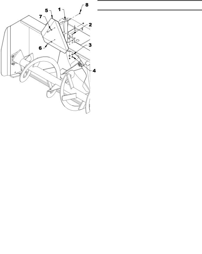
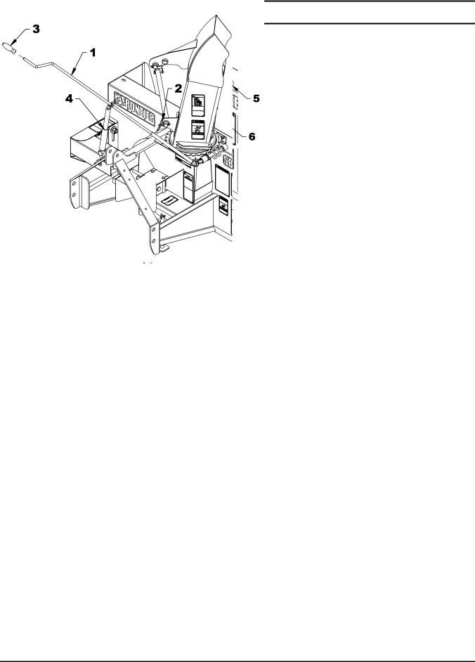
Installation of SMV Sign
(Figures 1-2)
1.Figure 1: Remove the 1/4" NC x 1" bolt, the flat washer and the 1/4" nylon insert nut (items 1-2-3) that fixes the sign (item 4) to the frame. Save the hardware.
2.Figure 2: Install the sign support (item 1) on the snowblower with two 1/4" NC x 1" bolts, two 1/4" flat washers and two 1/4" NC nylon insert nuts (items 2-3-4).
3.Figure 2: Using the hardware previously removed, attach the SMV sign (item 5) with two 1/4" NC x 1" bolts, two flat washers and two 1/4" nylon insert nut (items 6-7-8).
4.Remove the black protective film from the SMV sign.
|
|
|
|
|
|
|
|
|
|
|
Figure 1 |
|
|
|
Figure 2 |
|
|
|
|
|
|
|
|
|
|
|
|
|
|
|
|
|
|
|
|
|
|
|
|
|
|
|
|
|
OM 0369SB1148-A |
11 |

ASSEMBLY
Installation of Chute and Manual Rotation Kit 5RDF0016
(Figures 3-4-5-6)
NOTE: The rotation handle can be installed on the right or left side of the three point hitch.
1. Figure 3: Install the rotation bushing (item 2) over the chute base.
2.Figure 4: Insert the 1 11/16" plastic bushing (item 1) in the worm support bracket (item 2) and insert the longest end of the rotation worm (item 3).
3.Figure 4: Insert the 1 5/16" plastic bushing (item 4) in the welded tube of the snowblower (item 5).
4.Figure 4: Place the support (item 2) under the snowblower's right upper plate (item 6).
5.Figure 3: Place the chute (item 1) over the rotation bushing (item 2) and install the four retaining plates (item 3) with eight 1/4" x 3/4" bolts and eight serrated flange nuts (items 4-5). Tighten securely.
6.Figure 4: Insert the rotation tube (item 7) in the worm assembly aligning the holes, insert an Allen socket head capscrew 10-24 x 1" (item 8) making sure the screw head sinks into the rotation worm and secure with a nylon insert nut (item 9).
7.Figure 5: Install the rotation bracket (item 1) on the left or right arm of the three point hitch with two 3/8" NC x 1 1/4" bolts, 3/8" lockwashers and 3/8" nuts (items 2-3- 4). Tighten firmly.
9.Figure 5: Insert the handle support (item 9) in the bracket (item 5) adjusting the height of the support according to your needs and secure in place with a 3/8" x 1/2" square head setscrew (item 10).
10.Figure 5: Insert the grommet (item 11) in the handle support (item 9).
11.Figure 6: Insert the handle (item 1) in the handle support (item 4) and in the rotation tube. Select desired length, align nearest holes and secure with the 4 mm x 80mm hairpin (item 2). Install the plastic handle (item 3).
12.Figure 5: Once the snowblower is attached to the tractor, adjust handle position and height to ensure comfort and safe operation. Tighten setscrew (item 10) on the handle support as well as the 3/4" x 1 1/2" bolt, 3/4" lockwasher and 3/4" nut (items 6-7-8).
13.Figure 6: To insure the manual rotation functions properly, position the handle support (item 4) the closest possible to the top link mounting point of the three point hitch while making sure it does not come into contact with the operator's seat when the snowblower is fully raised.
14.Tighten all bolts according to the Torque Specification Table on page 50.
8. Figure 5: Attach the handle support bracket (item 5) to the rotation bracket (item 1) with a 3/4"NC x 1 1/4" bolt, lockwasher and nut (items 6-7-8) making sure to attach the brackets in the direction illustrated.
 CAUTION
To avoid personal injury, check the full lifting range of the snowblower, to ensure that the chute rotation handle is clear of the operator’s area when the snowblower is in raised position.
OM 0369SB1148-A |
12 |
ASSEMBLY
|
|
|
|
|
|
|
|
Figure 3 |
|
|
|
Figure 4 |
|
|
|
|
|
|
|
|
|
|
|
|
|
|
|
|
|
|
|
|
|
|
|
Figure 5 |
|
|
|
Figure 6 |
|
|
|
|
|
|
|
|
|
|
|
|
|
|
|
OM 0369SB1148-A |
13 |

ASSEMBLY
Installation of Chute and Hydraulic Rotation Kit 5RDF0017
(Figures 7-8-9)
1. Figure 7: Place the rotation bushing (item 2) over the chute base.
2.Figure 7: Place the chute (item 1) over the rotation bushing (item 2) and install the four retaining plates (item 3) with eight 1/4" x 3/4" bolts and eight serrated flange nuts (items 4-5). Tighten securely.
3.Figure 8: Attach the rotation bracket (item 1) in the 21/32’’ hole in the housing with a 5/8’’NC x 1 1/2’’ hex. bolt, a 5/8" lockwasher and a 5/8" nut (items 2-3-4).
Note: For SB1148 only. Place the 5/8" lg spacer (fig. 8, item 5) on the Ø9/16" x 1" slot in the housing before attaching the other end of the bracket.
4.Figure 8: Attach the other end of the bracket (item 1) in the Ø9/16" x 1" slot in the housing with a 1/2"NC x 1 1/4" hex. bolt, a Ø9/16" hole flat washer, a 1/2" lockwasher and a 1/2" hex. nut (items 6-7- 8-9). Tighten securely.
5.Figure 8: Attach the bell crank (item 10) by inserting the pivot bushing (item 11) in the tube and slide the bell crank between the flat bars of the rotation bracket (item 1). Secure everything with a 5/8’’NC x 5 1/2" hex. bolt, a 5/8" lockwasher and a 5/8" stover nut (items 12-13-14) in the order shown. Tighten firmly.
6.Figure 8: Grease both holes of the push arm generously (item 15) and slide the shortest section between the bell crank arms (item 10). Insert a 3/8’’ x 1 1/4"’ bolt from the top and secure with a 3/8’’NC stover nut (items 16-17). Tighten leaving some movement to the mechanism.
7.Figure 8: Slide the longest of the push arm (item 15) between the flat bars welded on the base of the chute. Secure everything with a 3/8’’ x 1 1/4" hex. bolt and a 3/8"NC stover nut (items 18-19). Tighten leaving some movement to the mechanism.
8.Figure 8: Attach the fixed section of the cylinder (item 20) to the rotation bracket (item 1, hole "B") and the sliding section to the bell crank (item 10, hole "A") placing a Ø 1 1/16" flat washer (item 21) between the cylinder yoke and the top of the bell crank and secure with the cylinder pins and the circlips. Point the hydraulic ports upward as illustrated.
NOTE: The 1 1/16" hole flat washer (item 21) prevents the cylinder yoke from rubbing on the bell crank.
9.Figure 9: Connect the 3/8" ends of both hoses (item 2) to the cylinder (item 1) and install a quick coupler with rubber dust cap (items 6-7) at the end of each hose.
10.Figure 9: Secure the hoses on the three point hitch with the hose clamp, 3/8" NC x 1 1/2" lg bolt and 3/8" NC nylon insert nut (items 4-3-5) and attach hoses together with the nylon tie wraps (item 8) where needed.
 CAUTION
To avoid serious personal injury. Escaping hydraulic/ diesel fluid under pressure can penetrate the skin causing serious injury.
•Do not use your hands to check for leaks. Use a piece of cardboard or paper to search for leaks.
1.Hydraulic hose
2.Cardboard
3.Magnifying glass
•Stop engine and relieve pressure before connecting or disconnecting lines.
•Tighten all connections before starting engine or pressurizing lines.
If any fluid is injected into the skin, obtain medical attention immediately or gangrene may result.
OM 0369SB1148-A |
14 |
 Loading...