

Page 1

Operation and Safety Manual
®
Original Instructions - Keep this manual with the machine at all times.
TOUCAN 10E
TOUCAN 26E
AS
English - Operation and Safety Manual
31210088
May 11, 2010
Page 2

Page 3

FOREWORD
FOREWORD
This manual is a very important tool! Keep it with the machine at all times.
The purpose of this manual is to provide owners, users, operators, lessors, and lessees with the precautions and
operating procedures essential for the safe and proper machine operation for its intended purpose.
Due to continuous product improvements, JLG Industries, Inc. reserves the right to make specification changes
without prior notification. Contact JLG Industries, Inc. for updated information.
31210088 – JLG Lift – a
Page 4
FOREWORD
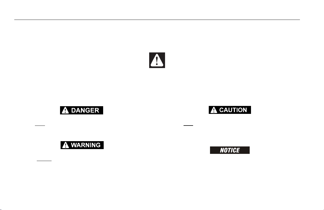
SAFETY ALERT SYMBOLS AND SAFETY SIGNAL WORDS
This is the Safety Alert Symbol. It is used to alert you to the potential personal
injury hazards. Obey all safety messages that follow this symbol to avoid possible
injury or death.
INDICATES AN IMMINENTLY HAZARDOUS SITUATION. IF NOT
AVOIDED, WILL RESULT IN SERIOUS INJURY OR DEATH. THIS DECAL
WILL HAVE A RED BACKGROUND.
INDICATES A POTENTIALLY HAZARDOUS SITUATION. IF NOT
AVOIDED, COULD
DECAL WILL HAVE AN ORANGE BACKGROUND.
RESULT IN SERIOUS INJURY OR DEATH. THIS
INDICATES A POTENTIALLY HAZARDOUS SITUATION. IF NOT
AVOIDED, MAY RESULT IN MINOR OR MODERATE INJURY. IT MAY
ALSO ALERT AGAINST UNSAFE PRACTICES. THIS DECAL WILL HAVE A
YELLOW BACKGROUND.
INDICATES INFORMATION OR A COMPANY POLICY THAT RELATES
DIRECTLY OR INDIRECTLY TO THE SAFETY OF PERSONNEL OR PROTECTION OF PROPERTY.
b – JLG Lift – 31210088
Page 5

THIS PRODUCT MUST COMPLY WITH ALL SAFETY RELATED BULLETINS. CONTACT JLG INDUSTRIES, INC. OR THE LOCAL AUTHORIZED
JLG REPRESENTATIVE FOR INFORMATION REGARDING SAFETYRELATED BULLETINS WHICH MAY HAVE BEEN ISSUED FOR THIS
PRODUCT.
For:
• Accident Reporting
• Product Safety Publications
• Current Owner Updates
• Questions Regarding
Product Safety
FOREWORD
• Standards and Regulations
Compliance Information
• Questions Regarding Special Product Applications
• Questions Regarding Product Modifications
JLG INDUSTRIES, INC. SENDS SAFETY RELATED BULLETINS TO THE
OWNER OF RECORD OF THIS MACHINE. CONTACT JLG INDUSTRIES,
INC. TO ENSURE THAT THE CURRENT OWNER RECORDS ARE
UPDATED AND ACCURATE.
JLG INDUSTRIES, INC. MUST BE NOTIFIED IMMEDIATELY IN ALL
INSTANCES WHERE JLG PRODUCTS HAVE BEEN INVOLVED IN AN
ACCIDENT INVOLVING BODILY INJURY OR DEATH OF PERSONNEL OR
WHEN SUBSTANTIAL DAMAGE HAS OCCURRED TO PERSONAL PROPERTY OR THE JLG PRODUCT.
Contact:
Product Safety and Reliability Department
JLG Industries, Inc.
13224 Fountainhead Plaza
Hagerstown, MD 21742
USA
or Your Local JLG Office
(See addresses on inside of manual cover)
In USA:
Toll Free: 877-JLG-SAFE (877-554-7233)
Outside USA:
31210088 – JLG Lift – c
Phone: 240-420-2661
Fax: 301-745-3713
E-mail: ProductSafety@JLG.com
Page 6

FOREWORD
Original Issue - July 10, 2008
Manual Revised - June 22, 2009
Manual Revised - May 11, 2010
REVISION LOG
d – JLG Lift – 31210088
Page 7

TABLE OF CONTENTS
SECTION - 1 - SAFETY PRECAUTIONS
1.1 GENERAL . . . . . . . . . . . . . . . . . . . . . . . . . . . . . . . 1-1
1.2 PRE-OPERATION . . . . . . . . . . . . . . . . . . . . . . . . . 1-1
Operator Training and Knowledge . . . . . . . . . . 1-1
Workplace Inspection . . . . . . . . . . . . . . . . . . . . 1-2
Machine Inspection. . . . . . . . . . . . . . . . . . . . . . 1-2
1.3 OPERATION . . . . . . . . . . . . . . . . . . . . . . . . . . . . . 1-3
General . . . . . . . . . . . . . . . . . . . . . . . . . . . . . . . 1-3
Trip and Fall Hazards . . . . . . . . . . . . . . . . . . . . 1-4
Electrocution Hazards. . . . . . . . . . . . . . . . . . . . 1-5
Tipping Hazards . . . . . . . . . . . . . . . . . . . . . . . . 1-6
Crushing and Collision Hazards . . . . . . . . . . . . 1-8
1.4 TOWING, LIFTING, AND HAULING . . . . . . . . . . . 1-8
1.5 ADDITIONAL HAZARDS / SAFETY. . . . . . . . . . . . 1-9
SECTION - 2 - USER RESPONSIBILITIES, MACHINE
PREPARATION, AND INSPECTION
2.1 PERSONNEL TRAINING. . . . . . . . . . . . . . . . . . . . 2-1
Operator Training . . . . . . . . . . . . . . . . . . . . . . . 2-1
Training Supervision . . . . . . . . . . . . . . . . . . . . . 2-1
Operator Responsibility . . . . . . . . . . . . . . . . . . 2-1
2.2 PREPARATION, INSPECTION, AND MAINTENANCE
Pre-Start Inspection . . . . . . . . . . . . . . . . . . . . . 2-4
General . . . . . . . . . . . . . . . . . . . . . . . . . . . . . . . 2-6
Function Check. . . . . . . . . . . . . . . . . . . . . . . . . 2-7
Tilt Sensor Check . . . . . . . . . . . . . . . . . . . . . . . 2-8
2-2
Overload Sensor Check (If Equipped) . . . . . . 2-9
Slack/Broken Chain Sensors Check . . . . . . . 2-10
SECTION - 3 - MACHINE CONTROLS AND INDICATORS
3.1 GENERAL . . . . . . . . . . . . . . . . . . . . . . . . . . . . . . . 3-2
3.2 CONTROLS AND INDICATORS . . . . . . . . . . . . . . 3-2
Ground Control Station . . . . . . . . . . . . . . . . . . 3-2
Platform Manual Descent Valves. . . . . . . . . . . 3-6
Mast Manual Descent Valve . . . . . . . . . . . . . . 3-6
Jib Manual Descent Valve . . . . . . . . . . . . . . . . 3-7
Manual Swinging Operating Devices . . . . . . . 3-7
Platform Control Station . . . . . . . . . . . . . . . . . 3-8
3.3 DECAL INSTALLATION . . . . . . . . . . . . . . . . . . . . 3-14
SECTION - 4 - MACHINE OPERATION
4.1 DESCRIPTION . . . . . . . . . . . . . . . . . . . . . . . . . . . . 4-1
4.2 OPERATING SPECIFICATIONS AND LIMITATIONS
Capacities . . . . . . . . . . . . . . . . . . . . . . . . . . . . 4-1
Stability . . . . . . . . . . . . . . . . . . . . . . . . . . . . . . 4-1
Grade and Side Slope . . . . . . . . . . . . . . . . . . . 4-3
4.3 OPERATION . . . . . . . . . . . . . . . . . . . . . . . . . . . . . 4-5
4.4 STEERING AND TRAVELLING (DRIVING) . . . . . . 4-5
Steering . . . . . . . . . . . . . . . . . . . . . . . . . . . . . . 4-6
Travelling (driving) . . . . . . . . . . . . . . . . . . . . . . 4-6
Drive Orientation System (DOS) . . . . . . . . . . . 4-7
. . 4-1
31210088 – JLG Lift – 1
Page 8

TABLE OF CONTENTS
4.5 RAISING AND LOWERING THE PLATFORM . . . . 4-7
Raising and lowering the mast . . . . . . . . . . . . 4-8
Raising and lowering the jib . . . . . . . . . . . . . . 4-8
4.6 SWINGING. . . . . . . . . . . . . . . . . . . . . . . . . . . . . . . 4-9
4.7 EMERGENCY CONTROL . . . . . . . . . . . . . . . . . . . 4-9
4.8 ALARMS . . . . . . . . . . . . . . . . . . . . . . . . . . . . . . . 4-10
Overload Warning Light/Alarm (If equipped) 4-10
Tilt Warning Light/Alarm . . . . . . . . . . . . . . . . 4-10
Slack Chain Warning Light/Alarm . . . . . . . . 4-11
Soft Touch Warning Light/Alarm (Option) . . 4-12
4.9 SHUT DOWN AND PARK . . . . . . . . . . . . . . . . . . 4-12
4.10 BATTERY CHARGING. . . . . . . . . . . . . . . . . . . . . 4-13
Battery Charger Fault Code. . . . . . . . . . . . . . 4-14
4.11 TIE-DOWN/LIFT LUGS . . . . . . . . . . . . . . . . . . . . 4-15
Tie Down . . . . . . . . . . . . . . . . . . . . . . . . . . . . 4-15
Lifting . . . . . . . . . . . . . . . . . . . . . . . . . . . . . . . 4-16
4.12 TOWING . . . . . . . . . . . . . . . . . . . . . . . . . . . . . . . 4-16
Electric Brake Release. . . . . . . . . . . . . . . . . . 4-17
SECTION - 5 - EMERGENCY PROCEDURES
5.1 GENERAL . . . . . . . . . . . . . . . . . . . . . . . . . . . . . . . 5-1
5.2 INCIDENT NOTIFICATION . . . . . . . . . . . . . . . . . . 5-1
5.3 EMERGENCY OPERATION. . . . . . . . . . . . . . . . . . 5-1
Operator Unable to Control Machine . . . . . . . 5-1
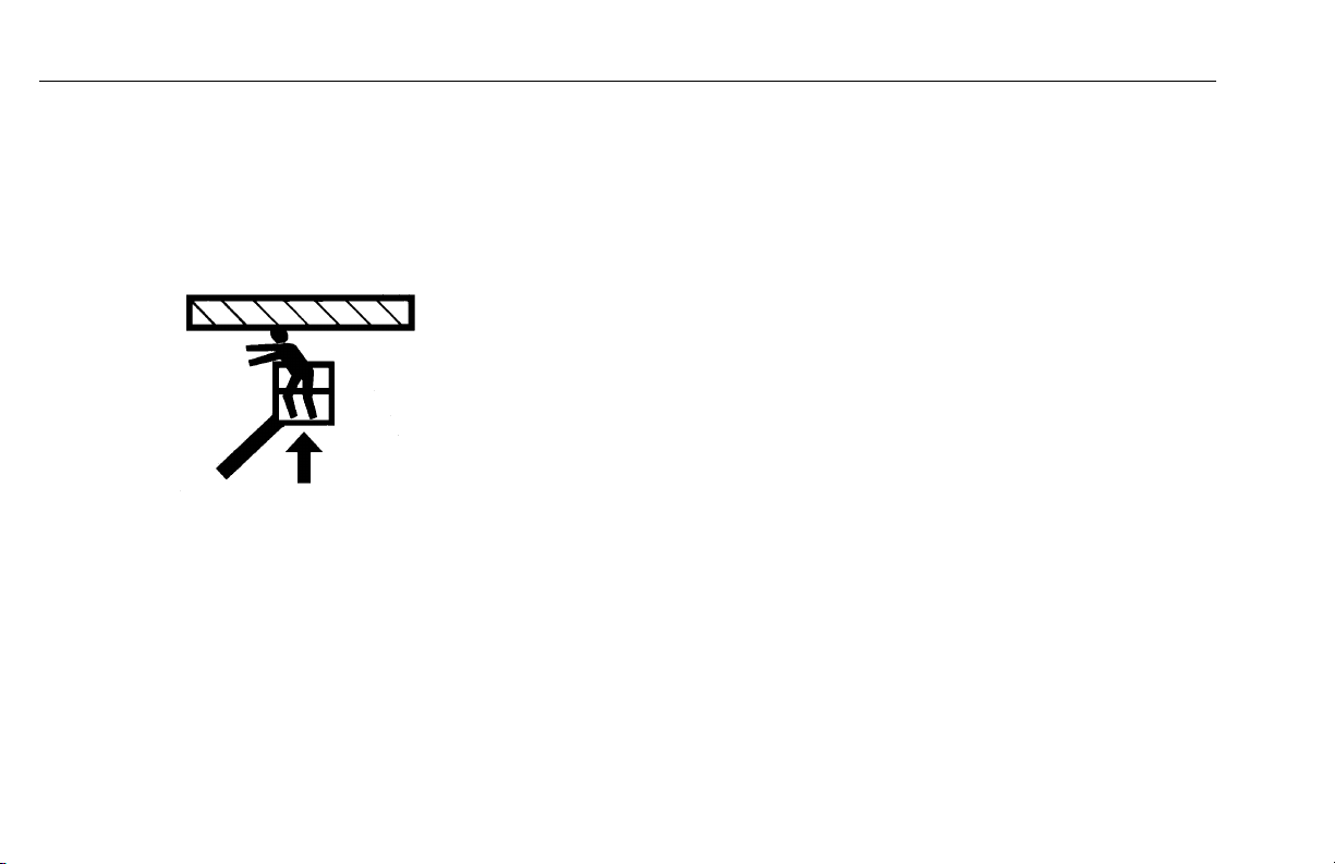
Platform or Jib Caught Overhead . . . . . . . . . . 5-2
5.4 PLATFORM MANUAL DESCENT. . . . . . . . . . . . . .5-2
5.5 EMERGENCY TOWING . . . . . . . . . . . . . . . . . . . . .5-2
SECTION - 6 - GENERAL SPECIFICATIONS & OPERATOR
MAINTENANCE
6.1 INTRODUCTION . . . . . . . . . . . . . . . . . . . . . . . . . .6-1
Other Publications Available . . . . . . . . . . . . . . 6-1
6.2 OPERATING SPECIFICATIONS. . . . . . . . . . . . . . .6-2
6.3 OPERATOR MAINTENANCE . . . . . . . . . . . . . . . . .6-9
6.4 CHASSIS HOOD REMOVAL . . . . . . . . . . . . . . . .6-10
6.5 BATTERY MAINTENANCE. . . . . . . . . . . . . . . . . .6-10
Battery Maintenance and Safety Practices . . 6-10
Filling System Draining . . . . . . . . . . . . . . . . . 6-12
Battery Voltage and Electrolyte Specific Gravity
Filling System Maintenance . . . . . . . . . . . . . . 6-15
Use of a Battery in a Cold Environment. . . . . 6-15
Battery Not Working Continuously or Inactive
Battery . . . . . . . . . . . . . . . . . . . . . . . . . . . . . . 6-15
Battery Troubleshooting. . . . . . . . . . . . . . . . . 6-16
6.6 OIL LEVEL/OIL FILTER . . . . . . . . . . . . . . . . . . . .6-17
Hydraulic Oil Check . . . . . . . . . . . . . . . . . . . . 6-17
Hydraulic Filter Replacement. . . . . . . . . . . . . 6-18
6.7 TIRES & WHEELS . . . . . . . . . . . . . . . . . . . . . . . .6-19
Tire Wear and Damage . . . . . . . . . . . . . . . . . 6-19
Wheel and Tire Replacement. . . . . . . . . . . . . 6-19
Wheel Installation . . . . . . . . . . . . . . . . . . . . . . 6-19
6-14
2 – JLG Lift – 31210088
Page 9

TABLE OF CONTENTS
6.8 LUBRICATION. . . . . . . . . . . . . . . . . . . . . . . . . . . 6-20
Overload System Spring Washer (If Equipped)
Swing Bearing Race . . . . . . . . . . . . . . . . . . . . 6-22
Swing Bearing Teeth. . . . . . . . . . . . . . . . . . . . 6-23
Mast Profiles Races. . . . . . . . . . . . . . . . . . . . . 6-24
Lifting Chains . . . . . . . . . . . . . . . . . . . . . . . . . 6-25
6.9 OVERLOAD SYSTEM VERIFICATION
(IF EQUIPPED) . . . . . . . . . . . . . . . . . . . . . . . . . . 6-26
6.10 TILT SENSOR VERIFICATION . . . . . . . . . . . . . . 6-27
6.11 SUPPLEMENTAL INFORMATION . . . . . . . . . . . 6-28
6.12 DIAGNOSTIC TROUBLE CODES (DTC) . . . . . . 6-28
Introduction . . . . . . . . . . . . . . . . . . . . . . . . . . . 6-28
6.13 DTC INDEX . . . . . . . . . . . . . . . . . . . . . . . . . . . . . 6-28
6.14 DTC CHECK TABLES . . . . . . . . . . . . . . . . . . . . . 6-29
0-0 Help Comments . . . . . . . . . . . . . . . . . . . . 6-29
2-1 Power-Up . . . . . . . . . . . . . . . . . . . . . . . . . 6-30
2-2 Platform Controls . . . . . . . . . . . . . . . . . . . 6-31
2-3 Ground Controls . . . . . . . . . . . . . . . . . . . . 6-33
2-5 Function Prevented. . . . . . . . . . . . . . . . . . 6-35
3-1 Line Contactor Open Circuit . . . . . . . . . . . 6-37
3-2 Line Contactor Short Circuit . . . . . . . . . . . 6-37
3-3 Ground Output Driver . . . . . . . . . . . . . . . . 6-38
4-2 Thermal Limit . . . . . . . . . . . . . . . . . . . . . . 6-41
4-4 Battery Supply. . . . . . . . . . . . . . . . . . . . . . 6-43
4-6 Transmission and Drive System . . . . . . . . 6-45
6-6 Communication. . . . . . . . . . . . . . . . . . . . . 6-46
6-21
6-7 Accessory . . . . . . . . . . . . . . . . . . . . . . . . 6-46
7-7 Electric Motor. . . . . . . . . . . . . . . . . . . . . . 6-47
8-1 Tilt Sensor . . . . . . . . . . . . . . . . . . . . . . . . 6-48
8-2 Platform Load Sense . . . . . . . . . . . . . . . . 6-49
8-6 Steering/Axle . . . . . . . . . . . . . . . . . . . . . . 6-49
9-9 Hardware . . . . . . . . . . . . . . . . . . . . . . . . . 6-50
SECTION - 7 - INSPECTION AND REPAIR LOG
31210088 – JLG Lift – 3
Page 10

TABLE OF CONTENTS
LIST OF TABLES
TABLE NO. TITLE PAGE NO.
1-1 Minimum Approach Distance (M.A.D.) . . . . . . . . . . 1-5
1-2 Beaufort Scale (For Reference Only) . . . . . . . . . . 1-10
2-1 Inspection and Maintenance Table. . . . . . . . . . . . . 2-3
3-1 T10E & T26E - Decal Installation. . . . . . . . . . . . . . 3-17
4-1 Battery Charger Fault Code . . . . . . . . . . . . . . . . . 4-14
6-1 Operating Specifications And Dimensions . . . . . . 6-2
6-2 Dimensions . . . . . . . . . . . . . . . . . . . . . . . . . . . . . . . 6-5
6-3 Tires Specifications . . . . . . . . . . . . . . . . . . . . . . . . . 6-5
6-4 Drive Motors - Hydraulic Power Unit. . . . . . . . . . . . 6-6
6-5 Battery Specifications . . . . . . . . . . . . . . . . . . . . . . . 6-7
6-6 Lubrication Specifications . . . . . . . . . . . . . . . . . . . . 6-7
6-7 Hydraulic Oil Specifications - Standard . . . . . . . . . 6-7
6-8 Hydraulic Oil Specifications - Optional . . . . . . . . . . 6-8
6-9 Wheel Torque Chart . . . . . . . . . . . . . . . . . . . . . . . 6-20
6-10 Recommended Viscosity Grade . . . . . . . . . . . . . . 6-25
7-1 Inspection and Repair Log . . . . . . . . . . . . . . . . . . . 7-1
4 – JLG Lift – 31210088
Page 11

TABLE OF CONTENTS
LIST OF FIGURES
FIGURE NO. TITLE PAGE NO.
2-1. Daily Walk-Around Inspection . . . . . . . . . . . . . . . . 2-5
2-2. Tilt Sensor. . . . . . . . . . . . . . . . . . . . . . . . . . . . . . . . 2-8
2-3. Overload Sensor. . . . . . . . . . . . . . . . . . . . . . . . . . . 2-9
2-4. Slack/Broken Chain Sensors . . . . . . . . . . . . . . . . 2-10
3-1. Basic Nomenclature - Location of Machine Controls
3-2. Ground Control Station . . . . . . . . . . . . . . . . . . . . . 3-3
3-3. Mast Manual Descent Valve . . . . . . . . . . . . . . . . . . 3-6
3-4. Jib Manual Descent Valve . . . . . . . . . . . . . . . . . . . 3-7
3-5. Manual Swinging Operating Devices. . . . . . . . . . . 3-8
3-6. Platform Control Indicator Panel . . . . . . . . . . . . . 3-10
3-7. Decal Installation - Sheet 1. . . . . . . . . . . . . . . . . . 3-14
3-8. Decal Installation - Sheet 2. . . . . . . . . . . . . . . . . . 3-15
3-9. Decal Installation - Sheet 3. . . . . . . . . . . . . . . . . . 3-16
4-1. Position of Least BACKWARD stability. . . . . . . . . . 4-2
4-2. Position of Least FORWARD stability. . . . . . . . . . . 4-2
4-3. Grade and Side Slope . . . . . . . . . . . . . . . . . . . . . . 4-4
4-4. Steer/Drive Controls . . . . . . . . . . . . . . . . . . . . . . . . 4-6
4-5. Drive Orientation System (DOS) . . . . . . . . . . . . . . 4-7
4-6. Lift Controls. . . . . . . . . . . . . . . . . . . . . . . . . . . . . . . 4-7
4-7. Swing Control . . . . . . . . . . . . . . . . . . . . . . . . . . . . . 4-9
4-8. Emergency Controls. . . . . . . . . . . . . . . . . . . . . . . 4-10
4-9. Machine Tie-Down . . . . . . . . . . . . . . . . . . . . . . . . 4-15
4-10. Lifting the Machine . . . . . . . . . . . . . . . . . . . . . . . . 4-16
4-11. Lifting the Machine Using a Fork Truck . . . . . . . . 4-16
. . 3-1
4-12. Electric Brake Release . . . . . . . . . . . . . . . . . . . . . 4-17
6-1. Range Diagram . . . . . . . . . . . . . . . . . . . . . . . . . . . . 6-4
6-2. Operator Maintenance & Lubrication Diagram . . . . 6-9
6-3. Chassis Hood Removal. . . . . . . . . . . . . . . . . . . . . 6-10
6-4. Level Indicators . . . . . . . . . . . . . . . . . . . . . . . . . . . 6-11
6-5. Adding Water to Batteries . . . . . . . . . . . . . . . . . . . 6-11
6-6. Filling System Draining . . . . . . . . . . . . . . . . . . . . . 6-12
6-7. Draining the Water . . . . . . . . . . . . . . . . . . . . . . . . 6-13
6-8. Measuring Electrolyte Specific Gravity . . . . . . . . . 6-14
6-9. Hydraulic Oil Check . . . . . . . . . . . . . . . . . . . . . . . 6-17
6-10. Hydraulic Filter Replacement . . . . . . . . . . . . . . . . 6-18
6-11. Wheel Lug Nut Tightening Sequence. . . . . . . . . . 6-19
6-12. Overload System Spring Washer Lubrication . . . 6-21
6-13. Swing Bearing Race Lubrication. . . . . . . . . . . . . . 6-22
6-14. Swing Bearing Teeth lubrication. . . . . . . . . . . . . . 6-23
6-15. Mast Profiles Races Lubrication . . . . . . . . . . . . . . 6-24
6-16. Overload System Verification . . . . . . . . . . . . . . . . 6-26
6-17. Jacking Points . . . . . . . . . . . . . . . . . . . . . . . . . . . . 6-27
31210088 – JLG Lift – 5
Page 12

TABLE OF CONTENTS
NOTES:
6 – JLG Lift – 31210088
Page 13

SECTION 1 – SAFETY PRECAUTIONS
SECTION 1. SAFETY PRECAUTIONS
1.1 GENERAL
This section outlines the necessary precautions for proper
and safe machine operation and maintenance. For proper
machine use, it is mandatory that a daily routine is established based on the content of this manual. A maintenance
program, using the information provided in this manual and
the Service and Maintenance Manual, must also be established by a qualified person and followed to ensure the
machine is safe to operate.
The owner/user/operator/lessor/lessee of the machine
should not operate the machine until this manual has been
read, training is accomplished, and operation of the machine
has been completed under the supervision of an experienced and qualified operator.
If there are any questions with regard to safety, training,
inspection, maintenance, application, and operation, please
contact JLG Industries, Inc. (“JLG”).
FAILURE TO COMPLY WITH THE SAFETY PRECAUTIONS LISTED IN
THIS MANUAL COULD RESULT IN MACHINE DAMAGE, PROPERTY DAMAGE, PERSONAL INJURY OR DEATH.
1.2 PRE-OPERATION
Operator Training and Knowledge
• Read and understand this manual before operating the
machine.
• Do not operate this machine until complete training is performed by authorized persons.
• Only authorized and qualified personnel can operate the
machine.
• Read, understand, and obey all DANGERS, WARNINGS,
CAUTIONS, and operating instructions on the machine
and in this manual.
• Use the machine in a manner which is within the scope of
its intended application set by JLG.
31210088 – JLG Lift – 1-1
Page 14

SECTION 1 – SAFETY PRECAUTIONS
• All operating personnel must be familiar with the emergency controls and emergency operation of the machine
as specified in this manual.
• Read, understand, and obey all applicable employer,
local, and governmental regulations as they pertain to
operation of the machine.
Workplace Inspection
• The operator is to take safety measures to avoid all hazards in the work area prior to machine operation.
• Do not operate or raise the platform while on trucks, trailers, railway cars, floating vessels, scaffolds or other equipment unless approved in writing by JLG.
• Do not operate the machine in hazardous environments
unless approved for that purpose by JLG.
• Be sure that the ground conditions are able to support the
maximum load shown on the decals located on the
machine.
• This machine can be operated in temperatures of 0
o
F (-20o C to 40o C). Consult JLG for operation out-
104
side this range.
• This machine must be used in a sufficient ambient light.
o
F to
Machine Inspection
• Before machine operation, perform inspections and functional checks. Refer to Section 2 of this manual for
detailed instructions.
• Do not operate this machine until it has been serviced and
maintained according to requirements specified in the
Service and Maintenance Manual.
• Be sure the trigger control, platform enable button and all
other safety devices are operating properly. Modification
of these devices is a safety violation.
MODIFICATION OR ALTERATION OF AN AERIAL WORK PLATFORM
SHALL BE MADE ONLY WITH WRITTEN PERMISSION FROM THE MANUFACTURER.
• Do not operate any machine on which safety or instruction
placards or decals are missing or illegible.
• Avoid any buildup of debris on the platform floor. Keep
mud, oil, grease, and other slippery substances from footwear and platform floor.
1-2 – JLG Lift– 31210088
Page 15

SECTION 1 – SAFETY PRECAUTIONS
1.3 OPERATION
General
• Do not use the machine for any purpose other than positioning personnel, their tools and equipment.
• Never operate a machine that is not working properly. If a
malfunction occurs, shut down the machine.
• Never slam a control switch or lever through neutral to an
opposite direction. Always return switch to neutral and
stop before moving the switch to the next function. Operate controls with slow and even pressure.
• Do not allow personnel to tamper with or operate the
machine from the ground with personnel in the platform,
except in an emergency.
• Do not carry materials directly on platform railing. Contact
JLG for approved material handling accessories.
• When two persons are in the platform, the operator shall
be responsible for all machine operations.
• Always ensure that power tools are properly stowed and
never left hanging by their cord from the platform work
area.
• Supplies or tools which extend outside the platform are
prohibited unless approved by JLG.
• When driving, always position extending structure over
rear axle in line with the direction of travel. Remember, if
extending structure is over the front axle, steer and drive
functions will be reversed.
• Do not assist a stuck or disabled machine by pushing,
pulling, or by using extending structure functions. Only
pull the unit from the tie-down lugs on the chassis.
• Do not place extending structure or platform against any
structure to steady the platform or to support the structure.
• Stow extending structure and shut off all power before
leaving machine.
31210088 – JLG Lift – 1-3
Page 16
SECTION 1 – SAFETY PRECAUTIONS
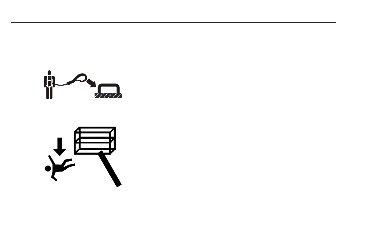
Trip and Fall Hazards
During operation, occupants in the platform must wear a full
body harness with a lanyard attached to an authorized lanyard anchorage point. Attach only one (1) lanyard per lanyard anchorage point.
• Before operating the machine, make sure all gates are
closed and fastened in their proper position.
• Keep both feet firmly positioned on the platform floor at all
times. Never use ladders, boxes, steps, planks, or similar
items on platform to provide additional reach.
• Never use the extending structure to enter or leave the
platform.
• Use extreme caution when entering or leaving platform.
Be sure that the platform is fully lowered. Face the
machine, maintain “three point contact” with the machine,
using two hands and one foot or two feet and one hand
during entry and exit.
1-4 – JLG Lift– 31210088
Page 17
SECTION 1 – SAFETY PRECAUTIONS
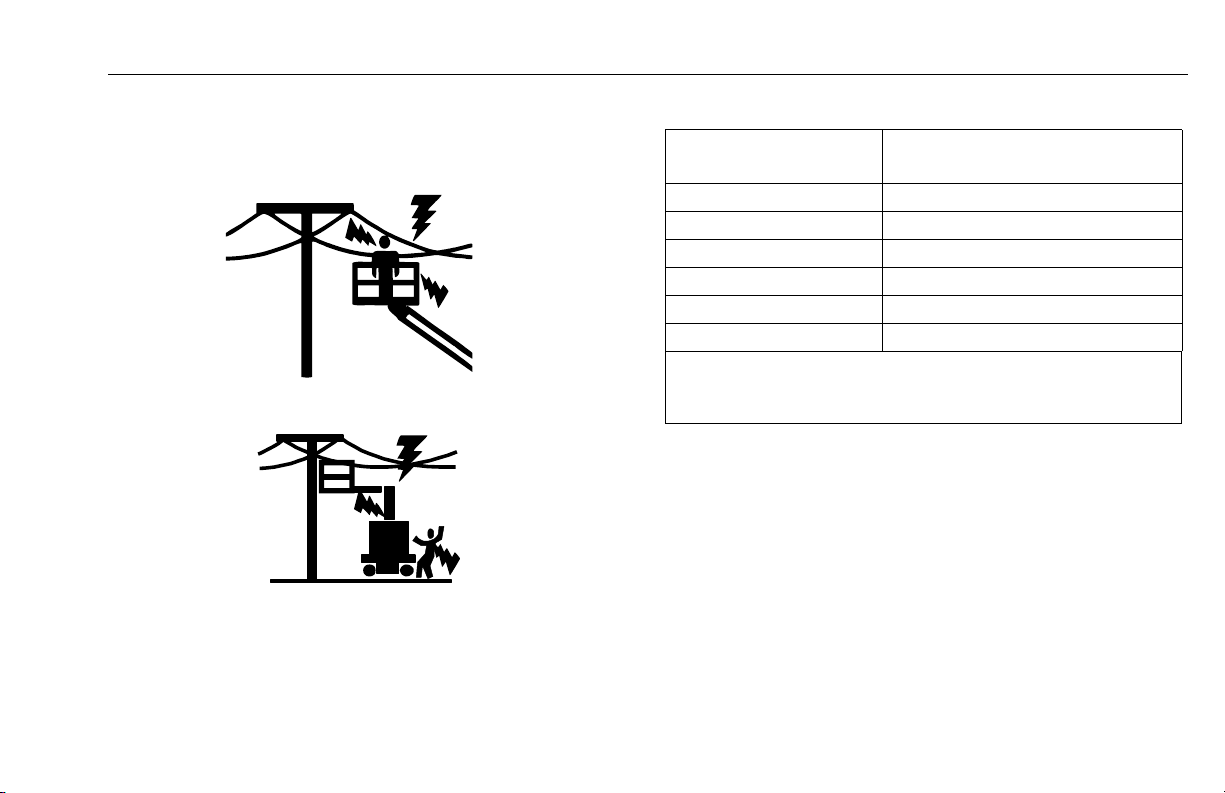
Electrocution Hazards
• This machine is not insulated and does not provide protection from contact or proximity to electrical current.
• Maintain distance from electrical lines, apparatus, or any
energized (exposed or insulated) parts according to the
Minimum Approach Distance (MAD) as shown in Table 1-1.
• Allow for machine movement and electrical line swaying.
Table 1-1. Minimum Approach Distance (M.A.D.)
Voltag e Ran ge
(Phase to Phase)
0 to 50 kV 3 (10)
Over 50 kV to 200 kV 5 (15)
Over 200kV to 350 kV 6 (20)
Over 350 kV to 500 KV 8 (25)
Over 500 kV to 750 kV 11 (35)
Over 750 kV to 1000 kV 14 (45)
NOTE: This requirement shall apply except where
employer, local or governmental regulations are
more stringent.
• Maintain a clearance of at least 3 m (10 ft.) between any
part of the machine and its occupants, their tools and their
equipment from any electrical line or apparatus carrying
up to 50 000 volts. A 0,3 m (1 ft.) additional clearance is
required for every additional 30 000 volts or less.
• The minimum approach distance may be reduced if insulating barriers are installed to prevent contact and the barriers are rated for the voltage of the line being guarded.
These barriers shall not be part of (or attached to) the
machine. The minimum approach distance shall be
reduced to a distance within the designed working dimen-
MINIMUM APPROACH DISTANCE
in Meters (Feet)
31210088 – JLG Lift – 1-5
Page 18
SECTION 1 – SAFETY PRECAUTIONS
sions of the insulating barrier. This determination shall be
made by a qualified person in accordance with employer,
local or governmental requirements for work practices
near energized equipment.
DO NOT MANEUVER MACHINE OR PERSONNEL INSIDE PROHIBITED
ZONE (MAD). ASSUME ALL ELECTRICAL PARTS AND WIRING ARE
ENERGIZED UNLESS KNOWN OTHERWISE.
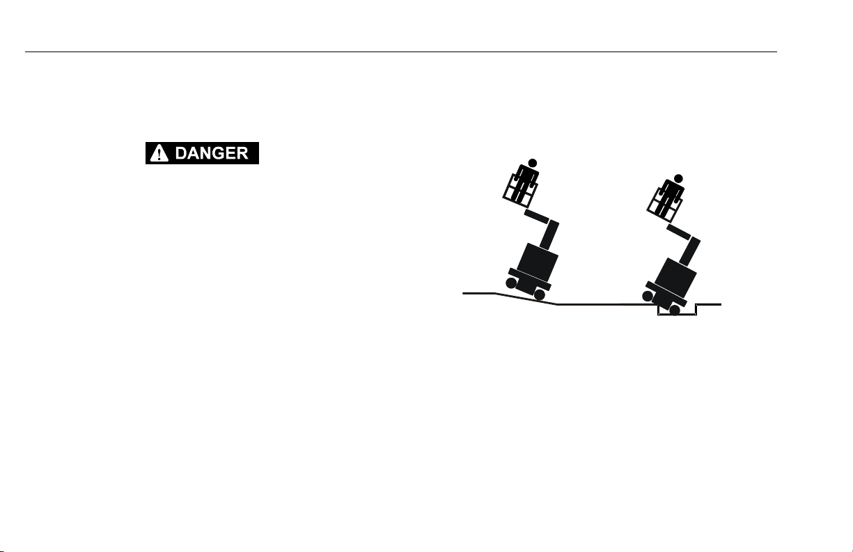
Tipping Hazards
• The user should be familiar with the surface before driving. Do not exceed the allowable sideslope and grade
while driving.
• Never exceed the maximum platform capacity. Distribute
loads evenly on platform floor.
• Before driving on floors, bridges, trucks, and other surfaces, check allowable capacity of the surfaces.
• Do not elevate platform or drive with platform elevated
while on a sloping, uneven, or soft surface.
1-6 – JLG Lift– 31210088
Page 19

SECTION 1 – SAFETY PRECAUTIONS
• Do not raise the platform or drive from an elevated position unless the machine is on firm, level and smooth surfaces.
• When travelling on grades (Refer to Section 4), the platform MUST be fully lowered. It is recommended to drive
up the grade in FORWARD gear and to REVERSE down
the slope.
• Keep the chassis of the machine at least 0,6 m (2 ft.) from
holes, bumps, drop-offs, obstructions, debris, concealed
holes, and other potential hazards on the floor/surface.
• Do not push or pull any object with the extending structure.
• Never attempt to use the machine as a crane. Do not tieoff machine to any adjacent structure.
• Do not operate the machine when wind conditions exceed
12.5 m/s (28 mph). Refer to Table 1-2, Beaufort Scale (For
Reference Only).
• Do not increase the surface area of the platform or the
load. Increase of the area exposed to the wind will
decrease stability.
• Do not increase the platform size with unauthorized deck
extensions or attachments.
• If extending structure assembly or platform is in a position
that one or more wheels are off the ground, all persons
must be removed before attempting to stabilize the
machine. Use cranes, forklift trucks, or other appropriate
equipment to stabilize machine.
31210088 – JLG Lift – 1-7
Page 20
SECTION 1 – SAFETY PRECAUTIONS
Crushing and Collision Hazards
• Approved head gear must be worn by all operating and
ground personnel.
• Check work area for clearances overhead, on sides, and
bottom of platform when lifting, swinging or lowering platform, and driving.
• During operation, keep all body parts inside platform railing.
• Always post a lookout when driving in areas where vision
is obstructed.
• Keep non-operating personnel at least 2m (6 ft.) away
from machine during all driving and swinging operations.
• Limit travel speed according to conditions of ground surface, congestion, visibility, slope, location of personnel,
and other factors which may cause hazard of collision or
injury to personnel.
• Be aware of stopping distances in all drive speeds. When
driving in high speed, slow down the machine using the
controller before stopping.
• Do not use high speed drive in restricted or close quarters
or when driving in reverse.
• Exercise extreme caution at all times to prevent obstacles
from striking or interfering with operating controls and persons in the platform.
• Be sure that operators of other overhead and floor level
machines are aware of the aerial work platform’s presence. Disconnect power to overhead cranes.
• Warn personnel not to work, stand, or walk under a raised
extending structure or platform. Position barricades on
floor if necessary.
1.4 TOWING, LIFTING, AND HAULING
• Never allow personnel in platform while towing, lifting, or
hauling.
• This machine should not be towed, except in the event of
emergency, malfunction, power failure, or loading/unloading. Refer to Emergency Towing Procedures Section of
this Manual for emergency towing procedures.
1-8 – JLG Lift– 31210088
Page 21

SECTION 1 – SAFETY PRECAUTIONS
• Ensure extending structure is in the stowed position prior
to towing, lifting or hauling. The platform and the tool tray
must be completely empty of tools.
• When lifting machine, lift only at designated areas of the
machine. Lift the unit with equipment of adequate capacity.
• Refer to the Machine Operation Section of this Manual for
lifting information.
1.5 ADDITIONAL HAZARDS / SAFETY
• Do not use machine as a ground for welding.
• When performing welding or metal cutting operations,
precautions must be taken to protect the chassis from
direct exposure to weld and metal cutting spatter.
• Battery fluid is highly corrosive. Avoid contact with skin
and clothing at all times.
• Charge batteries only in a well ventilated area.
31210088 – JLG Lift – 1-9
Page 22
SECTION 1 – SAFETY PRECAUTIONS
DO NOT OPERATE THE MACHINE WHEN WIND CONDITIONS EXCEED 28
MPH (12,5 M/S OR 45 KM/H).
Table 1-2. Beaufort Scale (For Reference Only)
Beaufort
Number
0 0 0-0.2 Calm Calm. Smoke rises vertically.
1 1-3 0.3-1.5 Light air Wind motion visible in smoke.
2 4-7 1.6-3.3 Light breeze Wind felt on exposed skin. Leaves rustle.
3 8-12 3.4-5.4 Gentle breeze Leaves and smaller twigs in constant motion.
4 13-18 5.5-7.9 Moderate breeze Dust and loose paper raised. Small branches begin to move.
5 19-24 8.0-10.7 Fresh breeze Smaller trees sway.
6 25-31 10.8-13.8 Strong breeze Large branches in motion. Whistling heard in overh ead wires.
7 32-38 13.9-17.1 Near Gale/Moderate Gale Whole trees in motion. Effort needed to walk against the wind.
8 39-46 17.2-20.7 Fresh Gale Twigs broken from trees. Cars veer on road.
9 47-54 20.8-24.4 Strong gale Light structure damage.
Wind Speed
mph m/s
Description Land Conditions
Umbrella use becomes difficult.
1-10 – JLG Lift– 31210088
Page 23

SECTION 2 – USER RESPONSIBILITIES, MACHINE PREPARATION, AND INSPECTION
SECTION 2. USER RESPONSIBILITIES, MACHINE PREPARATION, AND INSPECTION
2.1 PERSONNEL TRAINING
The aerial platform is a personnel handling device; so it is
necessary that it be operated and maintained only by trained
personnel.
Persons under the influence of drugs or alcohol or who are
subject to seizures, dizziness or loss of physical control must
not operate this machine.
Operator Training
Operator training must cover:
1. Use and limitations of the controls in the platform and at
the ground, emergency controls and safety systems.
2. Control labels, instructions, and warnings on the
machine.
3. Rules of the employer and government regulations.
4. Use of approved fall protection device.
5. Enough knowledge of the mechanical operation of the
machine to recognize a malfunction or potential malfunction.
6. The safest means to operate the machine where overhead obstructions, other moving equipment, and obstacles, depressions, holes or drop-offs exist.
7. Means to avoid the hazards of unprotected electrical
conductors.
8. Specific job requirements or machine application.
Training Supervision
Training must be done under the supervision of a qualified
person in an open area free of obstructions until the trainee
has developed the ability to safely control and operate the
machine.
Operator Responsibility
The operator must be instructed that he/she has the responsibility and authority to shut down the machine in case of a
malfunction or other unsafe condition of either the machine
or the job site.
31210088 – JLG Lift – 2-1
Page 24

SECTION 2 – USER RESPONSIBILITIES, MACHINE PREPARATION, AND INSPECTION
2.2 PREPARATION, INSPECTION, AND MAINTENANCE
The following table covers the periodic machine inspections
and maintenance recommended by JLG Industries, Inc.
Consult local regulations for further requirements for aerial
work platforms. The frequency of inspections and maintenance must be increased as necessary when the machine is
used in a harsh or hostile environment, if the machine is
used with increased frequency, or if the machine is used in a
severe manner.
JLG INDUSTRIES, INC. RECOGNIZES A FACTORY-TRAINED SERVICE
TECHNICIAN AS A PERSON WHO HAS SUCCESSFULLY COMPLETED
THE JLG SERVICE TRAINING SCHOOL FOR THE SPECIFIC JLG PRODUCT
MODEL.
2-2 – JLG Lift – 31210088
Page 25

SECTION 2 – USER RESPONSIBILITIES, MACHINE PREPARATION, AND INSPECTION
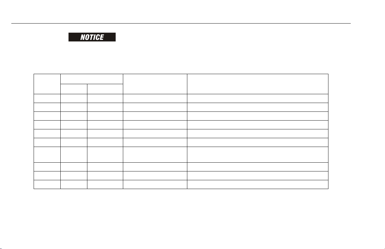
Table 2-1.Inspection and Maintenance Table
Type Frequency
Pre-Start Inspection
Pre-Delivery
Inspection
(See Note)
Freque nt Inspec tion
(See Note)
Annual Machine
Inspection
(See Note)
Preventative
Maintenance
NOTE: Inspection forms are available from JLG. Use the Service and Maintenance Manual to perform inspections.
Before using each day;
or whenever there’s an Operator change.
Before each sale, lease, or rental delivery. Owner, Dealer or User Qualified JLG Mechanic Service and Maintenance Manual
In service for 3 months or 150 hours, whichever comes first; or
Out of service for a period of more than 3
months; or
Purchased used.
Annually, no later than 13 months from the
date of prior inspection.
At intervals as specified in the Service and
Maintenance Manual.
Primary
Responsibility
User or Operator User or Operator Operator and Safety Manual
Owner, Dealer or User Qualified JLG Mechanic Service and Maintenance Manual
Owner, Dealer or User Factory-Trained Service
Owner, Dealer or User Qualified JLG Mechanic Service and Maintenance Manual
Service
Qualification
Technician (Recommended)
Reference
and applicable JLG inspection form
and applicable JLG inspection form
Service and Maintenance Manual
and applicable JLG inspection form
31210088 – JLG Lift – 2-3
Page 26
SECTION 2 – USER RESPONSIBILITIES, MACHINE PREPARATION, AND INSPECTION
Pre-Start Inspection
The Pre-Start Inspection must include each of the following:
1. Cleanliness – Check all surfaces for leakage (oil or battery fluid) or foreign objects. Report any leakage to the
proper maintenance personnel.
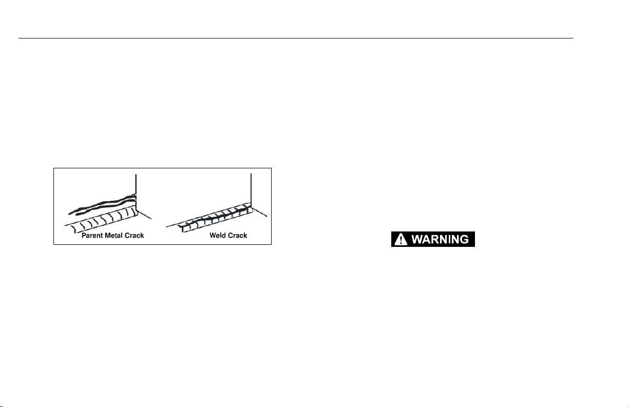
2. Structure – Inspect the machine structure for dents,
damage, weld or parent metal cracks or other discrepancies.
3. Decals and Placards – Check all for cleanliness and
legibility. Make sure none of the decals and placards are
missing. Make sure all illegible and missing decals and
placards are cleaned or replaced.
4. Operation and Safety Manuals – Make sure a copy of
the Operator and Safety manual, AEM Safety manual
(ANSI markets only), and ANSI Manual of Responsibility
(ANSI markets only) is enclosed in the weather resistant
storage container.
5. “Walk-Around” Inspection – Refer to Figure 2-1.
6. Battery – Charge as required.
7. Hydraulic Oil – Check the hydraulic oil level in the reser-
voir. Ensure hydraulic oil is added as required.
8. Accessories/Attachments - Reference the Operator
and Safety Manual of each attachment or accessory
installed upon the machine for specific inspection, operation, and maintenance instructions.
9. Function Check – Once the “Walk-Around” Inspection
is complete, perform a functional check of all systems in
an area free of overhead and ground level obstructions.
Refer to Section 4 for more specific operating instructions.
IF THE MACHINE DOES NOT OPERATE PROPERLY, TURN OFF THE
MACHINE IMMEDIATELY! REPORT THE PROBLEM TO THE PROPER
MAINTENANCE PERSONNEL. DO NOT OPERATE THE MACHINE UNTIL IT
IS DECLARED SAFE FOR OPERATION.
2-4 – JLG Lift – 31210088
Page 27
SECTION 2 – USER RESPONSIBILITIES, MACHINE PREPARATION, AND INSPECTION
Figure 2-1. Daily Walk-Around Inspection
31210088 – JLG Lift – 2-5
Page 28

SECTION 2 – USER RESPONSIBILITIES, MACHINE PREPARATION, AND INSPECTION
General
Begin the "Walk-Around Inspection" at Item 1, as noted on
the diagram. Continue checking each item in sequence for
the conditions listed in the following checklist.
TO AVOID POSSIBLE INJURY, BE SURE MACHINE POWER IS OFF.
DO NOT OPERATE MACHINE UNTIL ALL MALFUNCTIONS HAVE BEEN
CORRECTED.
INSPECTION NOTE: On all components, make sure there
are no loose or missing parts, that they are securely fastened,
and no visible damage, leaks or excessive wear exists in
addition to any other criteria mentioned.
1. Platform Assembly and Gate - Gate opens and closes
properly, manual in storage container. See inspection
note.
2. Platform & Ground Control Consoles - Placards
secure and legible, control levers and switches return to
neutral and emergency stop switches function properly.
3. Steering Assembly - See inspection note.
4. Wheel/Tire Assemblies - Properly secured, no missing
lug nuts. Inspect for worn tread, cuts, tears or other discrepancies. Inspect wheels for damage and corrosion.
See inspection note.
5. Hood Assemblies - See Inspection Note.
6. Hydraulic Cylinders- No visible damage, pivot pins and
hydraulic hoses undamaged, no leakage (hose connections - valve block).
7. Manual Descent - See Inspection Note.
8. Lifting Chains, Chain Yokes and Clevis Pins - Must be
installed and in good condition. Chains must be correctly tensioned and lubricated.
9. Hydraulic Pump/Motor Control Valves Installation/Oil
Level in Reservoir - Swing needle valve fully closed.
See Inspection Note.
10. Limit Switches - Mast limit switch(es), chain slack limit
switches and overload sensor (if equipped) are properly
installed and fastened. See inspection note.
2-6 – JLG Lift – 31210088
Page 29

SECTION 2 – USER RESPONSIBILITIES, MACHINE PREPARATION, AND INSPECTION
Function Check
Refer to Sections 3 & 4 for description and operation of machine
functions.
Control Stations
1. From the Ground Control Console with no load in the
platform:
a. Operate all functions to ensure proper operation.
b. While operating a mast lift-up movement, push in all
other function buttons. Mast lift-up movement
should continue and no other movement should
occur.
c. Ensure that all machine functions are disabled
when the emergency stop button is depressed.
d. Raise the mast about one meter (3 ft.), check if the
manual descent valve lowers the mast properly
(refer to Figure 3-3. for mast manual descent valve
location).
e. Raise the jib about half a meter (2 ft.), check if the
manual descent valve lowers the jib properly (Refer
to Figure 3-4).
2. From the Platform Control Console:
a. Ensure that the platform control console is firmly
secured.
b. Check that all guards protecting the switches are
securely in place.
c. Operate all functions including horn button to
ensure proper operation.
d. Ensure that all machine functions are disabled
when the emergency stop button is depressed.
e. Ensure all mast and jib functions stop when the
function enable button is released.
f. Ensure all drive functions stop when joystick trigger
is released.
g. With the mast elevated half a meter (2 ft.), on a
smooth, firm and level surface, drive the machine to
check if the high drive cutout speed-limit is
engaged. Drive speed will be reduced from a top
speed of 5.5 km/h to 0.75 km/h (3.40 mph to 0.45
mph) (Approx.).
h. Toucan 10E only: With the mast elevated 4.50 m
(14.8 ft.), on a smooth, firm and level surface, drive
the machine to check if the extra drive cutout
speed-limit is engaged. Drive speed will be reduced
to 0.40 km/h (0.25 mph) (Approx.).
31210088 – JLG Lift – 2-7
Page 30
SECTION 2 – USER RESPONSIBILITIES, MACHINE PREPARATION, AND INSPECTION
Figure 2-2. Tilt Sensor
i. Swing the superstructure either to the left or to the
right: when the jib is no longer over the rear axle,
the drive orientation system (DOS) indicator lights
up (Yellow).
Actuate a drive function: the drive function is disabled. The DOS indicator blinks, and the DOS override button must be used for the drive function to
operate.
j. With the machine in transport (stowed) position,
drive the machine on a grade, not to exceed the
rated gradeability and stop to ensure the brakes
hold.
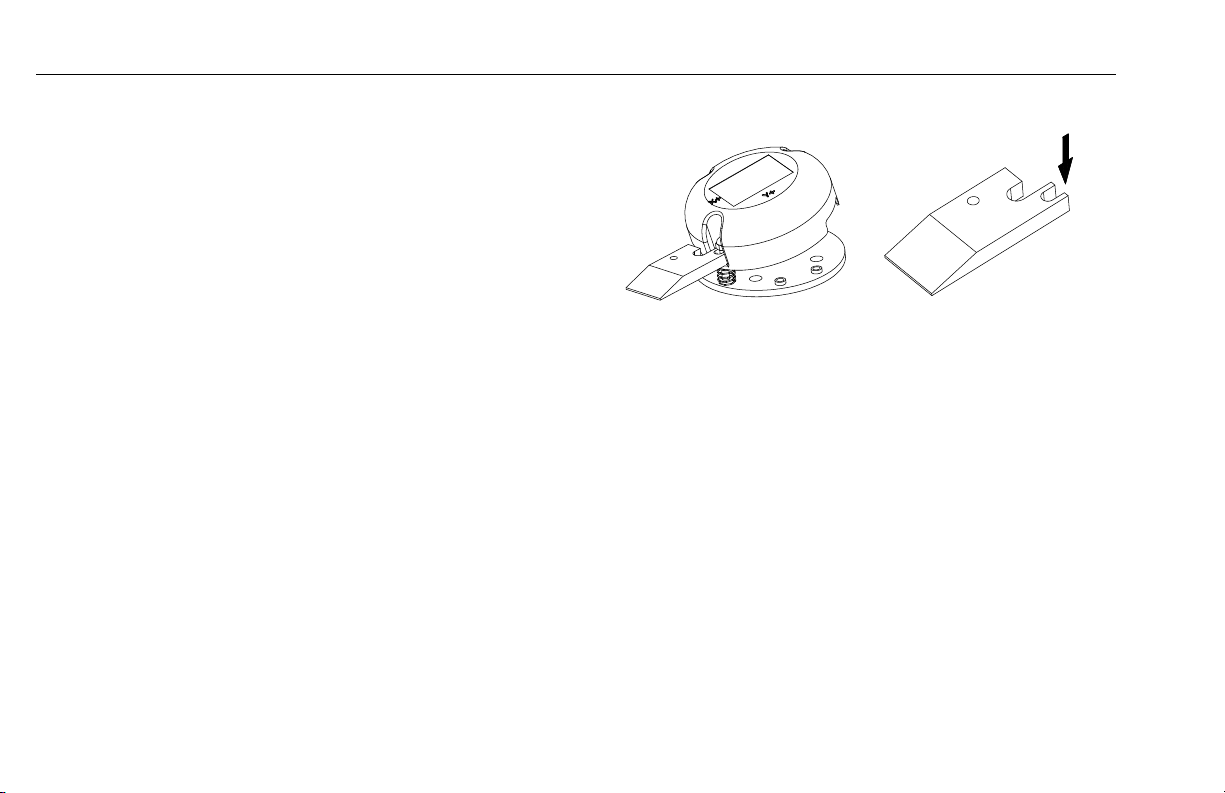
Tilt Sensor Check
Check the tilt indicator light/alarm to ensure proper operation. Wedge a block (P/N: ST2741 - located in the manual
storage container) to activate the tilt sensor and keep it tilted.
The tilt sensor is located on the chassis behind the right rear
wheel. Refer to Figure 2-2.
1. From the platform console :
- Raise the mast by approximately 1m (3 ft.).
a. Confirm an audible alarm sounds.
b. Verify the tilt indicator (red) blinks.
c. Check that the following functions are affected :
- Drive function disabled.
- Mast/Jib lift-up and swinging movements can be
performed only in creep mode.
2-8 – JLG Lift – 31210088
Page 31

SECTION 2 – USER RESPONSIBILITIES, MACHINE PREPARATION, AND INSPECTION
Figure 2-3. Overload Sensor
Overload Sensor Check (If Equipped)
Check the overload indicator light/alarm to ensure proper
operation. Wedge a block (P/N: ST2741 - located in the manual
storage container) to activate the overload sensor and keep it
activated. Refer to Figure 2-3.
1. From the Platform Control Console:
a. Confirm an audible alarm sounds.
b. Verify the overload indicator (Red) blinks.
c. Check that all functions are disabled.
2. From the Ground Control Panel:
a. Confirm an audible alarm sounds.
b. Verify the overload indicator (Red) blinks.
31210088 – JLG Lift – 2-9
Page 32

SECTION 2 – USER RESPONSIBILITIES, MACHINE PREPARATION, AND INSPECTION
Figure 2-4. Slack/Broken Chain Sensors
Slack/Broken Chain Sensors Check
Check the slack/broken chain indicator light/alarm and interlock
to ensure proper operation. Refer to Figure 2-4. for chain sensors
location (Qty:3). Wedge a block (P/N: ST2741 - located in the
manual storage container) to activate a slack chain sensor and
keep it activated.
1. From the Platform Control Console:
a. Confirm an audible alarm sounds.
b. Verify the slack chain indicator (Red) lights up.
c. Check when the slack chain indicator warning is
activated, the following functions are disabled:
- Mast/Jib lower
- Swing
- Drive
2. From the Ground Control Panel:
a. Confirm an audible alarm sounds.
b. Check when the slack chain indicator warning is
activated, the following functions are disabled:
- Mast/Jib lower
- Swing
c. Repeat check for each chain sensor.
2-10 – JLG Lift – 31210088
Page 33

SECTION 3 – MACHINE CONTROLS AND INDICATORS
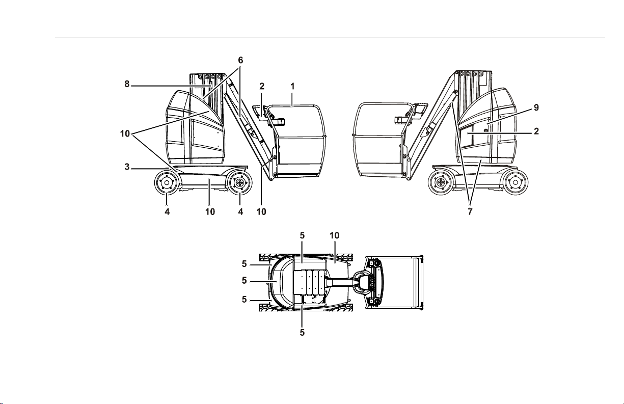
Figure 3-1. Basic Nomenclature - Location of Machine Controls
1- Driving wheels
2- Steering Wheels
3- Access door to Pump/Motor
Control valves
4- Counterweight
5- Jib
6- Ground Control Panel
7- Telescopic mast
8- Platform
9- Platform Control console
10- Manual Storage Container
11- Access door to battery/charger
12- Mast manual descent valve
13- Jib manual descent valve
14- Swinging motor release valve
15- Manual swinging operating device
SECTION 3. MACHINE CONTROLS AND INDICATORS
31210088 – JLG Lift – 3-1
Page 34

SECTION 3 – MACHINE CONTROLS AND INDICATORS
3.1 GENERAL
This section provides the necessary information needed to
understand controls and their functions.
THE MANUFACTURER HAS NO DIRECT CONTROL OVER MACHINE
APPLICATION AND OPERATION. THE USER AND OPERATOR ARE
RESPONSIBLE FOR CONFORMING WITH GOOD SAFETY PRACTICES.
3.2 CONTROLS AND INDICATORS
TO AVOID SERIOUS INJURY, DO NOT OPERATE MACHINE IF ANY CONTROL LEVERS OR TOGGLE SWITCHES CONTROLLING PLATFORM
MOVEMENT DO NOT RETURN TO THE OFF POSITION WHEN RELEASED.
Ground Control Station
DO NOT OPERATE FROM GROUND CONTROL STATION WITH PERSONNEL IN THE PLATFORM EXCEPT IN AN EMERGENCY.
WHEN THE MACHINE IS SHUT DOWN FOR OVERNIGHT PARKING OR
BATTERY CHARGING, THE PLATFORM/OFF/GROUND SELECTOR AND
THE EMERGENCY STOP SWITCHES MUST BE POSITIONED TO OFF TO
PREVENT DRAINING THE BATTERIES.
3-2 – JLG Lift – 31210088
Page 35

SECTION 3 – MACHINE CONTROLS AND INDICATORS
1- 5 Amp Circuit Breaker
2- Overload Warning Light (If equipped)
3- Multi-Display Indicator (MDI)
4- Platform/Off/Ground Selector Switch
5- Battery Charger Status Indicators (depending on equipment)
6- Emergency Stop Switch
7- Function Enable Button
8- Mast Lift/Lower Buttons
9- Jib Lift/Lower Buttons
10- Superstructure Swing Buttons
11- Brake Release Button
Figure 3-2. Ground Control Station
31210088 – JLG Lift – 3-3
Page 36

SECTION 3 – MACHINE CONTROLS AND INDICATORS
1. 5 Amp. Circuit Breaker - This circuit breaker protects
the control circuit in case of a short circuit or other malfunction.
2. Overload Warning Light (If equipped) - This lamp
(red), when blinking, indicates that the maximum rated
load in the platform is exceeded. The platform must be
safely unloaded until the alarm stops.
3. Multi-Display Indicator (MDI)
Hourmeter - The hourmeter symbol is lit when
the number of operated hours is displayed.
Speed reduction - Indicates that the maximum
drive speed is reduced when the platform is
out of transport position.
The wrench symbol is lit when a DTC (Diagnosis Troubleshooting Code) is displayed.
Five Digits Display
In normal operating condition, displays the
total amount of machine operation time accumulated.
In abnormal operating condition, displays a
DTC (Diagnosis Troubleshooting Code).
Alarm LED
Illuminates in abnormal operating condition
(when a DTC, other than 00xx DTC’s exists).
Battery Discharge Indicator (BDI).
This bar-graph is designed to let the operator
know the condition of the battery before starting to use the machine.
The last bar flashes when the level of charge is
less than 10%. The bar-graph is not displayed
when the batteries are completely discharged.
3-4 – JLG Lift – 31210088
Page 37

SECTION 3 – MACHINE CONTROLS AND INDICATORS
4. Platform/Off/Ground Selector Switch - A three-posi-
tion, key-operated power select switch supplies power
to the platform or ground controls and powers machine
down in the off position.
5. Battery Charger Status Indicators - This panel is
designed to give the operator an accurate reading on
the status of the battery charger. DEPENDING ON THE
CHARGER INSTALLED ON THE MACHINE THOSE
LIGHTS MAY NOT BE USED. REFER TO SECTION 4-10
OF THIS MANUAL FOR FURTHER INFORMATION.
GREEN- Charge complete
YELLOW- Charging in process
RED- Charging abnormal
6. Emergency Stop Switch - Depress the switch to stop
all functions of the machine. The switch must be turned
clockwise to restore the machine functions.
7. Function Enable Button - A membrane switch that must
be pushed in and held to enable the controls of the
ground control station.
8. Mast Lift/Lower Buttons - Membrane switches that provide raising or lowering of the mast (with the Function
Enable Switch (7) pushed in).
9. Jib Lift/Lower Buttons - Membrane switches that provide raising or lowering of the jib (with the Function
Enable Switch (7) pushed in).
10. Superstructure Swing Buttons - Membrane switches
that provide swinging of the superstructure to the right
or to the left (with the Function Enable Switch (7)
pushed in).
11. Brake Release Switch
DO NOT MANUALLY DISENGAGE THE BRAKES UNLESS THE MACHINE:
- IS IN TRANSPORT (STOWED) POSITION.
- IS ON A SMOOTH, FIRM AND LEVEL SURFACE.
- WHEELS CHOCKED OR MACHINE POSITIVELY CONNECTED TO TOW
VEHICLE.
The machine must be powered ON to Ground Control Mode
at the Platform/Off/Ground selector switch to operate the
brake release switch. Refer to section 4-12 of this manual for
further information.
31210088 – JLG Lift – 3-5
Page 38

SECTION 3 – MACHINE CONTROLS AND INDICATORS
Platform Manual Descent Valves
The platform manual descent valves are used in the event of
total power failure to lower the platform using gravity.
1. Push on the remote push bar (1) to lower the mast.
Release the bar when the platform is lowered to the
desired level.
2. To lower the jib once the mast is fully retracted, push in
the manual descent valve, override button (2). Release
the button when the platform is lowered to the desired
level.
KEEP BODY, HANDS AND ARMS OUT OF THE PATH OF THE MAST, THE
JIB AND THE PLATFORM WHILE LOWERING.
Mast Manual Descent Valve
- The mast manual descent valve remote push bar (1) (red)
located behind the access door to the pump/motor assembly.
Figure 3-3. Mast Manual Descent Valve
is
3-6 – JLG Lift – 31210088
Page 39

SECTION 3 – MACHINE CONTROLS AND INDICATORS
Jib Manual Descent Valve
- The jib manual descent button (2) is located on the jib cylinder valve.
Manual Swinging Operating Devices
The manual swinging operating devices are used in the event of
total power failure to manually swing the superstructure. Those
devices are composed of:
- a rotary valve (1) located on the pump/motor control valves
assembly to release the swinging motor (Refer to Figure 3-
5.).
- a pinion (2), located below the pump/motor control valves
compartment, that can be operated using, depending on
equipment, a square 1/2 inch ratchet wrench (a) or the folding lever (b).
Figure 3-4. Jib Manual Descent Valve
31210088 – JLG Lift – 3-7
Page 40

SECTION 3 – MACHINE CONTROLS AND INDICATORS
DO NOT RELEASE THE SWINGING MOTOR UNLESS THE MACHINE IS ON
A LEVEL SURFACE.
NEVER LEAVE THE MACHINE WITH A WRENCH ENGAGED ON THE PINION, WITH THE LEVER UNFOLDED OR WITH THE ROTARY VALVE
UNSCREWED.
Platform Control Station
TO AVOID SERIOUS INJURY, DO NOT OPERATE MACHINE IF ANY CONTROL LEVERS OR SWITCHES CONTROLLING PLATFORM MOVEMENT
DO NOT RETURN TO THE OFF OR NEUTRAL POSITION WHEN
Figure 3-5. Manual Swinging Operating Devices
RELEASED.
1. Open the access door to the pump/motor assembly.
2. Fully unscrew the rotary valve.
3. Depending on equipment, engage a square 1/2 inch
ratchet wrench in the square hole on top of the pinion or
lift the folding lever. Push on top of the pinion to engage
it in the turntable bearing teeth. Turn the lever clockwise
to swing the structure to the right or turn the lever counter-clockwise to swing the structure to the left.
4. When finished swinging, depending on equipment,
remove the wrench from the pinion or fold back the lever
until it is latched. Fully screw in the rotaty valve.
3-8 – JLG Lift – 31210088
Page 41

SECTION 3 – MACHINE CONTROLS AND INDICATORS
1. Indicator Panel
2. Emergency Stop Switch
3. Trigger Switch
4. Drive/Swing Functions Controller
5. Steer Switch
6. Mast/Jib Function Enable Button
7. Mast Lift Up/Down Joystick Controller
8. Jib Lift Up/Down Joystick Controller
9. Drive Orientation System (DOS) Override Button
10. Horn Button
31210088 – JLG Lift – 3-9
Page 42

SECTION 3 – MACHINE CONTROLS AND INDICATORS
1. Indicator panel
NOTE: The indicator panel uses different shaped symbols to alert
the operator to different types of operational situations
that could arise. The definition of those symbols are
explained below.
Indicates a potentially hazardous situation,
which if not corrected, could result in serious
injury or death. This indicator will be red.
Indicates an abnormal operating condition,
which if not corrected, may result in machine
interruption or damage. This indicator will be
yellow.
Indicates important information regarding the
operating condition, i.e. procedures essential
for safe operation. This indicator will be green.
Figure 3-6. Platform Control Indicator Panel
a- Control Enable Indicator
b- Creep Speed Indicator
c- System Distress Indicator
d- Drive Orientation Indicator
e- Tilt Indicator Warning Light
f- Overload Indicator Warning Light (If equipped)
g- Slack Chain Indicator Warning Light
h- Battery Discharge Indicator (BDI)
i- Soft Touch Indicator (Optional)
3-10 – JLG Lift – 31210088
Page 43

SECTION 3 – MACHINE CONTROLS AND INDICATORS
Green
Green
Yellow
Yellow
Red
Red
Red
Yellow
a. When lit, indicates that the controls are enabled. If
a function is not actuated within seven seconds, or
a seven seconds lapse between ending one function and beginning the next function occurs, the
enable light will go out and the enable must be
released and activated again to enable the controls.
When blinking, indicates that the machine is in a
configuration where the current activated function
is not permitted.
b. Indicates that the high drive cutout limit-speed is
engaged (the mast is out of transport (stowed)
position).
c. This light indicates that the control system has
detected an abnormal condition. This lamp when
actuated is flashing a DTC (Diagnostic Troubleshooting Code). For an explanation of these codes
and items, the operator can or cannot correct, see
Section 6 Diagnostic Trouble Codes (DTC).
d. When the structure is swung beyond the rear tires
or further in either direction, the Drive Orientation
indicator will illuminate. This is a signal for the operator to verify that the drive control is being operated
in the proper direction (i.e. controls reversed situations).
e. Indicates that the chassis is out of level (refer to
machine specifications for max. allowable slope
angle). If the mast is out of the transport (stowed)
position and the chassis is out of level, an audible
alarm will sound.
f. (If equipped) - Indicates that the maximum rated
load in the platform is exceeded. In addition to the
warning indicator, an audible alarm sounds. The
platform must be unloaded until the alarm stops.
g. Indicates that a slack chain condition has been
detected. In addition to the warning indicator, an
audible alarm will sound as long as the chain slack
chain condition exists.
h. This set of lights indicates the charge level of the
battery.
i. (If equipped) - Indicates the Soft Touch frame is
against an obstacle. In addition to the warning indicator, an audible alarm sounds. Once illuminated,
only the reverse movement to the one that caused
the contact with the obstacle can be operated in
Creep mode.
31210088 – JLG Lift – 3-11
Page 44

SECTION 3 – MACHINE CONTROLS AND INDICATORS
2. Emergency Stop Switch - A two-position, red, emergency stop switch, when positioned to ON furnishes
operating power to the platform control station. In addition, the switch can be used to turn off power to the
function controls in the event of an emergency. Power is
turned off by depressing the switch and power is turned
on by turning the switch clockwise to pull it out.
3. Trigger Switch - This switch located at the front of the
controller acts as an enable and must be depressed
before operating the drive, steer and swinging functions.
When released, the function being operated will stop.
4. Drive/Swing Functions Controller - This dual axis joystick controls drive and swinging functions. The speed
of both functions is proportionally controlled by the distance of travel of the hand joystick.
Drive - Engage the trigger switch lever (3) with the joystick in neutral position then move the control handle
forward to drive the machine forward or move the control handle backward to drive the machine backward.
Swing - Engage the trigger switch lever (3) with the joystick in neutral position then toggle the control handle to
the left to swing the superstructure to the left or toggle
the control handle to the right to swing to the right.
5. Steer Switch - The thumb-operated steer switch on top
of the control handle activates the steer wheels in the
direction activated (right or left).
6. Mast/Jib Function Enable Button - This button is used
to enable mast and jib functions. It must be depressed
and held before actuating a mast or jib function. When
released, the function being operated will stop.
7. Mast Lift Up/Down Joystick Controller - This fingertip,
single axis, joystick controller operates Mast Lift Up and
Lift Down functions.
With the joystick controller in neutral position, push-in
and hold the Mast/Jib Function Enable Button (6), moving the joystick backward will raise the mast and moving
the joystick forward will lower the mast. The speed of the
movements is proportionally controlled by the distance
of travel of the joystick.
8. Jib Lift Up/Down Joystick Controller - This fingertip,
single axis, joystick controller operates Jib Lift Up and
Jib Lift Down functions.
With the joystick controller in neutral position, push-in
and hold the Mast/Jib Function Enable Button (6), moving the joystick backward will raise the jib and moving
the joystick forward will lower the jib. The speed of the
movements is proportionally controlled by the distance
of travel of the joystick.
3-12 – JLG Lift – 31210088
Page 45

SECTION 3 – MACHINE CONTROLS AND INDICATORS
9. Drive Orientation Override Button - When the jib is
swung beyond the rear tires or further in either direction,
the Drive Orientation indicator will illuminate. Before driving, locate the black/white orientation arrows on both
the chassis and the platform controls. Push and release
the override switch and within 3 seconds slowly move
the Drive/Steer control to actuate drive or steer. Move
the drive control toward the arrow matching the
intended direction of machine travel.
10. Horn - This button, when activated, permits the operator
to warn job site personnel when the machine is operating in the area.
31210088 – JLG Lift – 3-13
Page 46

SECTION 3 – MACHINE CONTROLS AND INDICATORS
3.3 DECAL INSTALLATION
Figure 3-7. Decal Installation - Sheet 1
3-14 – JLG Lift – 31210088
Page 47

SECTION 3 – MACHINE CONTROLS AND INDICATORS
Figure 3-8. Decal Installation - Sheet 2
31210088 – JLG Lift – 3-15
Page 48

SECTION 3 – MACHINE CONTROLS AND INDICATORS
Figure 3-9. Decal Installation - Sheet 3
3-16 – JLG Lift – 31210088
Page 49

SECTION 3 – MACHINE CONTROLS AND INDICATORS
Table 3-1. T10E & T26E - Decal Installation
Item # T10E
1701499 1701499 1701499 1701499 1701499
1
1701640 1701640 1701640 1701640 1701640
2
1703811 1703811 1703811 1703811 1703811
3
1703814 1703814 1703814 1703814 1703814
4
1704016 1704016 1704016 1704016 1704016
5
1704277 1704277 1704277 1704277 1704277
6
1705781 1705781 1705781 1705781 1705781
7
1705803 1703785 1703785 1703785 1704031
8
1706493 -- -- -- --
9
1706740 1706740 1706740 1706740 1706740
10
1706764 1704885 1704885 1704885 1704885
11
12
13
14
15
16
17
18
AU0149 AU0149 AU0149 AU0149 AU0149
AU1423 AU1423 AU1423 AU1423 AU1423
-- -- -- -- -AU1825 AU1825 AU1825 AU1825 AU1825
AU2095 AU2095 AU2095 AU2095 AU2095
AU2096 AU2096 AU2096 AU2096 AU2096
AU2097 AU2097 AU2097 AU2097 AU2097
T26E
ANSI
T26E
CSA
T26E
Spanish
T26E
Portuguese
Item # T10E
19
20
21
22
23
24
25
26
27
28
29
30
31
32
33
34
35
36
AU2098 AU2098 AU2098 AU2098 AU2098
AU2099 AU2099 AU2099 AU2099 AU2099
AU2100 AU2122 AU2122 AU2122 AU2122
AU2101 AU2101 AU2101 AU2101 AU2101
AU2102 AU2120 AU2120 AU2120 AU2148
AU2103 AU2118 AU2118 AU2118 AU2150
AU2104 AU2104 AU2104 AU2104 AU2104
AU2105 AU2105 AU2105 AU2105 AU2105
AU2106 AU2116 AU2116 AU2116 AU2116
AU2107 AU2119 AU2119 AU2119 AU2147
AU2108 AU2117 AU2117 AU2117 AU2149
AU2109 AU2121 AU2142
-- -- AU2140 AU2147 AU2152
-- -- 1705514 -- --
-- --
-- --
-- --
-- --
T26E
ANSI
T26E
CSA
AU2141 AU2148 AU2153
AU2143 AU2149 AU2154
AU2144 AU2150 AU2155
AU2145 1704031 1704023
T26E
Spanish
AU2146 AU2151
T26E
Portuguese
31210088 – JLG Lift – 3-17
Page 50

SECTION 3 – MACHINE CONTROLS AND INDICATORS
NOTES:
3-18 – JLG Lift – 31210088
Page 51

SECTION 4 – MACHINE OPERATION
SECTION 4. MACHINE OPERATION
4.1 DESCRIPTION
This machine is a self-propelled hydraulic lift equipped with a
work platform on the end of an elevating and rotating mast.
The primary operator control station is in the platform. From this
control station, the operator can drive and steer the machine in
both forward and reverse directions. The operator can raise or
lower the mast and the jib or swing the mast to the left or right.
Standard mast swing is 172.5 degree left and right of the
stowed position. The machine has a Ground Control Station
which will override the Platform Control Station. Ground Controls operate mast and jib lift and swing and are to be used in an
emergency to lower the platform to the ground should the operator in the platform be unable to do so. The Ground Control is
also to be used in Pre-Start Inspection.
4.2 OPERATING SPECIFICATIONS AND LIMITATIONS
Capacities
The mast and the jib can be raised above horizontal with or
without any load in the platform if:
1. Machine is positioned on a smooth, firm and level surface.
2. Load is within manufacturer’s rated design capacity.
3. All machine systems are functioning properly.
4. Machine is as originally equipped from JLG.
Stability
Machine stability is based on two (2) conditions which are called
FORWARD and BACKWARD stability. The machine’s position of
least FORWARD stability is shown in (See Figure 4-2.) and its
position of least BACKWARD stability is shown in (See Figure 4-
1.).
TO AVOID FORWARD OR BACKWARD TIPPING, DO NOT OVERLOAD
MACHINE OR OPERATE THE MACHINE ON AN OUT-OF-LEVEL SURFACE.
31210088 – JLG Lift – 4-1
Page 52

SECTION 4 – MACHINE OPERATION
Figure 4-1. Position of Least BACKWARD stability
Figure 4-2. Position of Least FORWARD stability
4-2 – JLG Lift – 31210088
Page 53

Grade and Side Slope
With the machine in transport mode, travelling is limited by two
factors: gradeability and side slope (Refer to Figure 4-3.).
Gradeability is the percent of grade of the incline the machine
can climb. Side slope is the angle of the surface the machine
can be driven across. Refer to Table 6-1.
With the mast out of transport (stowed) position, the machine
must not be operated on grade or side slopes greater than that
is specified in Table 6-1.
SECTION 4 – MACHINE OPERATION
31210088 – JLG Lift – 4-3
Page 54

SECTION 4 – MACHINE OPERATION
Figure 4-3. Grade and Side Slope
4-4 – JLG Lift – 31210088
Page 55

SECTION 4 – MACHINE OPERATION
4.3 OPERATION
1. At ground control station, position the key-select switch
to PLATFORM.
2. Position the emergency stop switch to the on (out) position by turning it clockwise.
3. At platform control station, position the emergency stop
switch to the on (out) position by turning it clockwise.
NOTE: If at any time during operation, the machine remains idle
for a period exceeding 2 hours, machine power will be
shut down. The emergency stop switch(es) must be recycled to start machine again.
TO AVOID SERIOUS INJURY, DO NOT OPERATE MACHINE IF ANY CONTROL LEVERS OR SWITCHES CONTROLLING THE PLATFORM MOVEMENT DOES NOT RETURN TO THE OFF OR NEUTRAL POSITION WHEN
RELEASED.
IF THE PLATFORM DOES NOT STOP WHEN CONTROL LEVER OR THE
ENABLE BUTTON/TRIGGER SWITCH IS RELEASED, USE THE EMERGENCY STOP SWITCH TO STOP THE MACHINE.
4.4 STEERING AND TRAVELLING (DRIVING)
DO NOT DRIVE WITH MAST OUT OF TRANSPORT (STOWED) POSITION
EXCEPT ON A SMOOTH, FIRM AND LEVEL SURFACE FREE OF
OBSTRUCTIONS AND HOLES.
TO AVOID LOSS OF TRAVEL CONTROL OR "TIP OVER", DO NOT DRIVE
MACHINE ON GRADES OR SIDE SLOPES EXCEEDING THOSE SPECIFIED
IN SECTION 6.
USE EXTREME CAUTION WHEN DRIVING IN REVERSE AND AT ALL
TIMES WHEN THE PLATFORM IS ELEVATED.
BEFORE DRIVING, LOCATE THE BLACK/WHITE ORIENTATION ARROWS
ON BOTH THE CHASSIS AND THE PLATFORM CONTROLS. MOVE THE
DRIVE CONTROLS IN A DIRECTION MATCHING THE DIRECTIONAL
ARROW FOR THE INTENDED DIRECTION OF TRAVEL.
31210088 – JLG Lift – 4-5
Page 56

SECTION 4 – MACHINE OPERATION
Figure 4-4. Steer/Drive Controls
Steering
1.
Squeeze and hold the
2. Activate the thumb switch on top of the joystick to right
(2) for travelling right or to left (3) for travelling left.
When released, the thumb switch will return to the center-off position and the wheels will remain in the previously selected position. To return the wheels to the
straightened position, the switch must be activated in
the opposite direction until the wheels are centered.
trigger switch (1)
on front of the joystick.
Travelling (driving)
1. With all control levers in neutral position, squeeze and
hold the trigger switch (1) on front of the joystick.
2. Move the joystick forward (4) (within 7 seconds after the
trigger has been actuated) to drive forward or move the
joystick backward (5) to drive in reverse. The speed of
the movement is proportionally controlled by the distance of travel of the joystick.
3. Return the controller to its centered (neutral) position to
stop, then release the trigger.
IF THE TILT INDICATOR WARNING LIGHT/ALARM IS ACTIVATED WHILE
DRIVING WITH THE MAST RAISED, LOWER THE MAST COMPLETELY
AND DRIVE TO A SMOOTH, FIRM AND LEVEL SURFACE.
4-6 – JLG Lift – 31210088
Page 57

SECTION 4 – MACHINE OPERATION
Drive Orientation System (DOS)
When the structure is swung beyond the rear wheels or further
in either direction, the drive orientation indicator (1) will illuminate and drive will be disabled.
1. Push and release the override button (2), and within 3
seconds move the drive/steer controls to activate drive
or steer.
2. Before driving, locate the black/white directional arrows
on both the chassis and the platform controls (3). Move
the drive control joystick in a direction matching the
directional arrow, for the intended direction of travel.
4.5 RAISING AND LOWERING THE PLATFORM
DO NOT RAISE THE PLATFORM EXCEPT ON A SMOOTH, FIRM AND
LEVEL SURFACE FREE OF OBSTRUCTIONS AND HAZARDS.
ENSURE THE AREA BENEATH THE PLATFORM IS FREE FROM
PERSONNEL PRIOR TO LOWERING THE PLATFORM.
Figure 4-6. Lift Controls
Figure 4-5. Drive Orientation System (DOS)
31210088 – JLG Lift – 4-7
Page 58

SECTION 4 – MACHINE OPERATION
Raising and lowering the mast
1. With all control levers in neutral position, push in and
hold the green enable button (1) on the left hand side
of the console.
2. To raise the mast, move the mast controller backward
(2). The speed of the movement is proportionally con-
trolled by the distance of travel of the joystick.
3. Return the controller to its centered (neutral) position to
stop.
4. To lower the mast, move the mast controller forward
(3). The speed of the movement is proportionally con-
trolled by the distance of travel of the joystick.
5. Return the controller to its centered (neutral) position to
stop, then release the enable button.
Raising and lowering the jib
1. With all control levers in neutral position, push in and
hold the green enable button (1) on the left hand side
of the console.
2. To raise the jib, move the jib controller backward (4).
The speed of the movement is proportionally controlled
by the distance of travel of the joystick.
3. Return the controller to its centered (neutral) position to
stop.
4. To lower the jib, move the jib controller forward (5).
The speed of the movement is proportionally controlled
by the distance of travel of the joystick.
5. Return the controller to its centered (neutral) position to
stop, then release the enable button.
4-8 – JLG Lift – 31210088
Page 59

SECTION 4 – MACHINE OPERATION
1
2
3
4.6 SWINGING
DO NOT SWING THE SUPERSTRUCTURE EXCEPT ON A SMOOTH, FIRM
AND LEVEL SURFACE, FREE OF OBSTRUCTIONS AND HOLES.
WHEN SWINGING, MAKE SURE THERE IS AMPLE ROOM FOR THE JIB
TO CLEAR SURROUNDING WALLS, PARTITIONS AND EQUIPMENT.
Figure 4-7. Swing Control
1. With all control levers in neutral position, squeeze and
hold the trigger switch (1) on front of the joystick.
2. Move the joystick to the desired direction: right (2) or
left (3). The speed of the movement is proportionally
controlled by the distance of travel of the joystick.
3. Return the controller to its centered (neutral) position to
stop, then release the trigger.
4.7 EMERGENCY CONTROL
The machine has a Ground Control Station which will override
the Platform Control Station. Ground controls operate Lift and
Swing, and are to be used in an emergency to lower the platform to the ground, should the operator in the platform be
unable to do so.
DO NOT OPERATE FROM GROUND CONTROL STATION WITH
PERSONNEL IN THE PLATFORM EXCEPT IN AN EMERGENCY.
ENSURE THE AREA BENEATH THE PLATFORM IS FREE OF PERSONNEL
OR OBSTACLES PRIOR TO LOWERING.
31210088 – JLG Lift – 4-9
Page 60

SECTION 4 – MACHINE OPERATION
1. Position the key-select switch (1) to GROUND.
2. Push and hold the enable button (2).
3. Actuate the appropriate function button (3) until the
desired elevation or position of the platform is achieved.
4.8 ALARMS
Overload Warning Light/Alarm (If equipped)
When the maximum rated load in the platform is exceeded, RED
light indicators at both the ground and the platform control stations will blink and an audible alarm will sound. When the overload indicator warning is activated, all machine functions are
disabled. The platform must be safely unloaded until the alarm stops.
Tilt Warning Light/Alarm
When the chassis is out of level (Refer to Table 6-1), the RED
light indicator at platform control station will illuminate. If the
mast is out of transport (stowed) position, and the chassis is out
of level an audible alarm will sound.
IF THE WARNING LIGHT IS ILLUMINATED WHEN THE MAST IS RAISED,
LOWER THE MAST AND REPOSITION MACHINE SO THAT IT IS LEVEL
Figure 4-8. Emergency Controls
BEFORE ELEVATING THE MAST.
4-10 – JLG Lift – 31210088
Page 61

SECTION 4 – MACHINE OPERATION
When the tilt indicator warning is activated, the following functions are affected:
-The Drive function is disabled out of stowed position.
-Mast/Jib Lift and Swinging movements switch to Creep
mode.
When the tilt indicator warning is activated, control the machine
as follows:
1. Lower the mast.
2. Return the platform in line with the chassis.
3. Lower the Jib.
4. Drive the machine to a smooth, firm and level surface.
AVOID RAISING THE MAST, OPERATING THE JIB OR SWINGING WITH
THE MAST RAISED WHEN THE MACHINE IS OUT OF LEVEL. ALWAYS
LOWER THE MAST AS MUCH AS POSSIBLE BEFORE OPERATING THE
JIB OR SWINGING.
Slack Chain Warning Light/Alarm
When the system detects a slack chain condition, the RED light
indicator at platform control station will illuminate and an audible
alarm will sound.
Slack chain condition is generally caused by the platform or the
jib coming to rest on an obstacle while lowering.
When the slack chain indicator warning is activated, all machine
functions, except mast and jib raising movements are disabled.
Procedure to follow in case the slack chain indicator warning is
activated:
1. Raise the mast or the jib (generally the reverse movement to the one that caused the alarm to be activated).
This will re-tension the chain(s) and stop the alarm.
2. Examine surroundings to identify the cause.
3. Perform the movement which will clear the machine and
prevent contact with the obstacle.
IF THE EXAMINATION OF THE SURROUNDINGS DOES NOT REVEAL ANY
POSSIBLE OBSTACLE, DISCONTINUE OPERATION IMMEDIATELY.
DO NOT USE MANUAL DESCENT CONTROLS.
PLATFORM OCCUPANTS MUST BE RESCUED AND THE MAST MECHANISM SERVICED BY A QUALIFIED TECHNICIAN.
31210088 – JLG Lift – 4-11
Page 62

SECTION 4 – MACHINE OPERATION
Soft Touch Warning Light/Alarm (Option)
When the bumper under the work platform is against an obstacle, the YELLOW light indicator at platform control station will
illuminate and an audible alarm will sound. Only the reverse
movement to the one that caused the contact with the obstacle
can be controlled in the Creep mode.
NOTE: This feature is only operational when the machine is con-
trolled from the platform control station.
4.9 SHUT DOWN AND PARK
Shut down and park the machine as follows:
1. Drive the machine to a reasonably well-protected and
well-ventilated area.
2. Ensure the platform is fully lowered.
3.
Turn the platform/ground selector switch to off and remove
the key to disable the machine and prevent unauthorized
use.
4. At the ground control station, position the emergency
stop switch to the off (pushed in) position.
5. If necessary, cover the platform console, the instruction
placards, caution and warning decals so that they will be
protected from hostile environment.
6. If necessary, charge the battery.
4-12 – JLG Lift – 31210088
Page 63

SECTION 4 – MACHINE OPERATION
4.10 BATTERY CHARGING
NOTE: Be sure that the machine is parked in a well-ventilated
area before charging begins.
ONLY PLUG THE CHARGER INTO A PROPERLY INSTALLED AND
GROUNDED OUTLET. DO NOT USE GROUND ADAPTORS OR MODIFY
PLUG. DO NOT TOUCH NON-INSULATED PORTION OF OUTPUT CONNECTOR OR NON-INSULATED BATTERY TERMINAL.
DO NOT OPERATE CHARGER IF THE AC SUPPLY CORD IS DAMAGED OR
IF THE CHARGER HAS RECEIVED A SHARP BLOW, BEEN DROPPED OR
OTHERWISE DAMAGED IN ANY WAY.
ALWAYS DISCONNECT THE AC SUPPLY BEFORE MAKING OR BREAKING
THE (POS/NEG) CONNECTIONS TO THE BATTERY.
DO NOT OPEN OR DISASSEMBLE CHARGER.
NOTE: It is not necessary to charge the battery if the electrolyte
specific gravity has not dropped under 1.240kg/l. Doing
so regularly, will greatly reduce battery life.
The battery charger AC input plug (1) is located on the battery
compartment.
1. Connect the AC input plug (1) to a grounded outlet.
2. When first powered up, the charger will go through a
short LED indicator self-test. The battery charger light’s
on the Ground Control Station will flash in sequence for
two seconds.
3. The batteries are fully charged when the green light on
the battery charger status panel (Ground Control Station) is illuminated.
NOTE: If the charger is left plugged in, the charger will automati-
cally restart a complete charge cycle if the batteries voltage drops below a minimum voltage or 30 days has
elapsed.
31210088 – JLG Lift – 4-13
Page 64

SECTION 4 – MACHINE OPERATION
Battery Charger Fault Code
If a fault occured during charging, the red (Fault LED located on the Ground Control Station panel) will flash with a code corresponding to
the error. Refer to the table following for the flash codes and their removal.
If required, further general and troubleshooting information about the battery charger can be found in the charger manufacturers Owner’s
Guide included in the manual storage box mounted on the machine.
Table 4-1. Battery Charger Fault Code
Flash(s)
1 Battery voltage high Auto-recover - Indicates a high batter y pack voltage.
2 Battery voltage low
3 Charge time-out
4 Check battery
5 Over-temperature Auto-recover - Indicates charger has shut down due to high internal temp.
6
Fault Remedy
Auto-recover - Indicates either a battery pack failure, battery pack not connected to charger or battery volts per cell is less
than 0.5 VDC. Check the battery pack and connections.
Indicates the batteries did not charge in the allowed time. This could occur if the batteries are a larger capacity than the algorithm is intended for or if the batteries are damaged, old, or in poor condition.
Indicates the batteries could not be trickle charged up to the minimum voltage per cell level required for the charge to be
started.
Indicates that the battery will not accept charge current, or an internal fault has been detected in the charger. This fault will
Charger Internal
Fault
nearly always be set within the first 30 seconds of operation. Once it has been determined that the batteries and connections
are not faulty and fault 6 is again displayed after interrupting AC power for at least 10 seconds, the charger must be brought
to a qualified service depot.
4-14 – JLG Lift – 31210088
Page 65

4.11 TIE-DOWN/LIFT LUGS
Tie Down
When transporting the machine:
- Platform must be fully lowered in the stowed position.
- Machine must be tied down to the truck bed or trailer deck as
shown in Figure 4-9.
SECTION 4 – MACHINE OPERATION
Figure 4-9. Machine Tie-Down
31210088 – JLG Lift – 4-15
Page 66

SECTION 4 – MACHINE OPERATION
Lifting
When lifting the machine:
- Platform must be fully lowered in the stowed position.
- Remove all loose items from the machine.
- Attach lifting straps/chains at BOTH lifting lugs as shown in
Figure 4-10.
Figure 4-10. Lifting the Machine
The machine may also be lifted using a fork truck:
- Fully lower the mast and the jib.
- Position the platform in line with the chassis with the jib over
the rear axle.
- Fork lift as shown in Figure 4-11.
VERIFY THE CAPACITY OF THE FORK TRUCK AND OF ITS EQUIPMENT.
FORK LIFT ONLY AT THE DESIGNATED POINTS.
WHEN DRIVING THE FORK TRUCK, KEEP THE WORK PLATFORM AS
NEAR TO THE GROUND AS POSSIBLE (BUT WITH A SUFFICIENT CLEARANCE FOR THE WHEELS NOT TO CONTACT THE GROUND).
Figure 4-11. Lifting the Machine Using a Fork Truck
4.12 TOWING
It is not recommended that this machine be towed, except in the
event of an emergency or a machine power failure.
4-16 – JLG Lift – 31210088
Page 67

SECTION 4 – MACHINE OPERATION
Electric Brake Release
NOTE: Electrical release of the brakes requires enough battery
power to hold the brakes in released mode until destination is reached.
1. Chock wheels or secure machine with tow vehicle.
2. Position the key-select-switch to ground control station
(1).
3. Push and hold the enable push button (2).
4. Depress the brake release button (3) for one second to
release the brakes. Once the brakes are released, an
acoustic (discontinuous sound) alarm is triggered.
5. When finished towing depress and hold both the enable
push button (2) and the brake release button (3)
again or power the machine down at the ground control
station to re-engage the brakes.
NOTE: Any action to remove electrical power from the brakes
such as, depressing the ground control emergency stop
switch, or switching the key switch to OFF or PLATFORM
MODE will re-engage the brakes.
Figure 4-12. Electric Brake Release
31210088 – JLG Lift – 4-17
Page 68

SECTION 4 – MACHINE OPERATION
NOTES:
4-18 – JLG Lift – 31210088
Page 69

5.1 GENERAL
SECTION 5 – EMERGENCY PROCEDURES
SECTION 5. EMERGENCY PROCEDURES
This section explains the steps to be taken in case of an
emergency situation during operation.
5.2 INCIDENT NOTIFICATION
JLG Industries, Inc. must be notified immediately of any incident involving a JLG product. Even if no injury or property
damage is evident, the factory should be contacted by telephone and provided with all necessary details.
In USA:
JLG Phone: 877-JLG-SAFE (554-7233)
Outside USA: 240-420-2661
E-mail: ProductSafety@JLG.com
Failure to notify the manufacturer of an incident involving a
JLG Industries product within 48 hours of such an occurrence may void any warranty consideration on that particular
machine.
FOLLOWING ANY INCIDENT, THOROUGHLY INSPECT THE MACHINE
AND TEST ALL FUNCTIONS FIRST FROM THE GROUND CONTROLS,
THEN FROM THE PLATFORM CONTROLS. DO NOT LIFT ABOVE 3 M (10
FT.) UNTIL YOU ARE SURE THAT ALL DAMAGE HAS BEEN REPAIRED, IF
REQUIRED, AND THAT ALL CONTROLS ARE OPERATING CORRECTLY.
5.3 EMERGENCY OPERATION
Operator Unable to Control Machine
IF THE PLATFORM OPERATOR IS PINNED, TRAPPED OR
UNABLE TO OPERATE OR CONTROL MACHINE:
1. Other personnel should operate the machine from
ground controls only as required.
2. Other qualified personnel in the platform may use the
platform controls. DO NOT CONTINUE OPERATION IF
CONTROLS DO NOT FUNCTION PROPERLY.
3. Cranes, forklift trucks or other equipment can be used to
stabilize motion of the machine.
31210088 – JLG Lift – 5-1
Page 70

SECTION 5 – EMERGENCY PROCEDURES
Platform or Jib Caught Overhead
If the platform or the jib become jammed or snagged in overhead structures or equipment, rescue platform occupants
prior to freeing the machine.
5.4 PLATFORM MANUAL DESCENT
The platform manual descent valves are used in the event of a
total power failure to retract and lower the platform using gravity.
Refer to Section 3-2 PLATFORM MANUAL DESCENT AND
SWING.
5.5 EMERGENCY TOWING
Towing this machine is discouraged. However provisions for
towing the machine in emergency situations have been incorporated. Refer to Section 4-12 TOWING.
5-2 – JLG Lift – 31210088
Page 71

SECTION 6 – GENERAL SPECIFICATIONS & OPERATOR MAINTENANCE
SECTION 6. GENERAL SPECIFICATIONS & OPERATOR MAINTENANCE
6.1 INTRODUCTION
This section of the manual provides additional necessary information to the operator for proper operation and maintenance of
this machine.
The maintenance portion of this section is intended as information to assist the machine operator to perform daily maintenance tasks only, and does not replace the more thorough
Preventive Maintenance and Inspection Schedule included in
the Service and Maintenance Manual.
Other Publications Available
Service and Maintenance Manual.................. 31210090
Illustrated Parts Manual.................................. 31210091
Hydraulic Schematic .......................................... FL0153
Electrical Schematic...........................................ELE251
31210088 – JLG Lift – 6-1
Page 72

SECTION 6 – GENERAL SPECIFICATIONS & OPERATOR MAINTENANCE
6.2 OPERATING SPECIFICATIONS
Table 6-1. Operating Specifications And Dimensions
Model TOUCAN 10E (CE) TOUCAN 26E (ANSI)
200 kg
Maximum Work Load
Maximum Manual Force 400 N 150 lbf (667 N)
Maximum Operating Wind Speed 45 km/h (12.5 m/s) 28 mph
Maximum Elevated Travel Grade(Gradeability and Side slope) 3.5% (2°) 0°
Maximum Stowed Travel Grade (Gradeability)(Reference Figure 4.3) 25% (14°) 25% (14°)
Maximum Stowed Travel Grade (Side slope)(Reference Figure 4.3) 8.7% (5°) 8.7% (5°)
Maximum Drive Speed
Stowed
Mast Elevated (1)
Mast Fully Elevated (2)
Inside Turning Radius
Outside Turning Radius
Maximum Platform Height 8.10m 26.5’ (8.10m)
Horizontal Reach
From centerline of machine
From rear wheel edge
From side wheel edge
Up and Over Clearance 6.50 m 21.3’ (6.50 m)
(2 persons
+ 40 kg material)
5.50 km/h
0.75 km/h
0.40 km/h
0.55 m
1.99 m
2.58 m
1.78 m
2.08 m
500 lbs (227 kg)
3.4 mph (5.5 km/h)
0.47 mph (0.75 km/h)
0.47 mph (0.75 km/h)
21.7” (0.55 m)
82.7” (2.10 m)
8.67’ (2.64 m)
6.04’ (1.84 m)
6.76’ (2.06 m)
6-2 – JLG Lift – 31210088
Page 73

SECTION 6 – GENERAL SPECIFICATIONS & OPERATOR MAINTENANCE
Table 6-1. Operating Specifications And Dimensions
Approximate Gross Machine Weight 2990 kg 6834 lbs (3100 kg)
Maximum Tire Load (per wheel) 1680 kg 3485 lbs (1580 kg)
Maximum Hydraulic Pressure 18 MPa 2600 psi
Maximum Ground Bearing Pressure 21 kg/cm² 285 psi
Electrical System Voltage 24V 24V
(1) Up to 7.20 m (23.6’) - Platform height with the jib fully raised
(2) Above 7.20 m (23,6’) - Platform height with the jib fully raised - Toucan 10E only.
31210088 – JLG Lift – 6-3
Page 74

SECTION 6 – GENERAL SPECIFICATIONS & OPERATOR MAINTENANCE
Figure 6-1. Range Diagram
6-4 – JLG Lift – 31210088
Page 75

SECTION 6 – GENERAL SPECIFICATIONS & OPERATOR MAINTENANCE
Table 6-2. Dimensions
DESCRIPTION
Platform Height - Stowed 0.35 m 14” (0.35 m)
Platform Height - Elevated 8.10 m 26.5’ (8.10 m)
Working Height 10.10 m 32.5’ (10.10 m)
Overall Stowed Machine Height 1.99 m 78.5” (1.99 m)
Overall Machine Width 0.99 m 45” (1.14 m)
Overall Machine Length 2.82 m 109” (2.77 m)
Platform Size - Length 0.70 m 27.5” (0.70 m)
Platform Size - Width 0.90 m 35.4” (0.90 m)
Model
TOUCAN 10E
Model
TOUCAN 26E
Table 6-3. Tires Specifications
DESCRIPTION
Size Ø406 x 125 mm Ø406 x 125 mm
Wheel Bolts Torque 142-163 Nm 105-120 ft.lbs
Model
TOUCAN 10E
Model
TOUCAN 26E
31210088 – JLG Lift – 6-5
Page 76

SECTION 6 – GENERAL SPECIFICATIONS & OPERATOR MAINTENANCE
Table 6-4. Drive Motors - Hydraulic Power Unit
DESCRIPTION Model TOUCAN 10E - TOUCAN 26E
Drive Motor
Hydraulic
Power
Unit
(1) - Including Tank
Motor
Displacement 3.1 cc/rev - (0.19 cu.in/rev)
Pump
Flow Rate 9.6 l/mn @ 13 MPa - (2.54 gal/min @ 1900 psi)
Tank 6 l (5.5 l usable) - (1.59 gal (1.46 gal usable))
Capacity
Hydraulic System (1) Approx. 9 l - (2.38 gal)
Vol tag e 1 5 VAC
Powe r 0.8 5 kW
Vol tage 24 VDC
Powe r 3 kW
6-6 – JLG Lift – 31210088
Page 77

SECTION 6 – GENERAL SPECIFICATIONS & OPERATOR MAINTENANCE
Table 6-5. Battery Specifications
DESCRIPTION Model TOUCAN 10E - TOUCAN 26E
Voltage (24 VDC) 12 cells of 2 V
NOTE: Aside from JLG recommendations, it is not advisable to
mix oils of different brands or types, as they may not contain the same required additives or be of comparable viscosities.
Table 6-7. Hydraulic Oil Specifications - Standard
Amp Hour (Standard battery) 240 Amp Hour @ 5 HR. Rate
Battery Weight (Approx.) 220 kg (485 lbs)
Table 6-6. Lubrication Specifications
KEY SPECIFICATIONS e.g.
A Extreme Pressure - Multi Purpose Grease MOBILUX EP2
COMPLEX EP2
BOpen Gear Lube MOBILTAC 81
C Non Detergent Mineral Oil (*) MOBIL DTE 16M
D Synthetic Chain Oil Fuchs VT 800
(*) To be adapted to the machine’s operating conditions. See Table 6-10
SPECIFICATION NERVOFLUID VG 32 MOBIL DTE 13M
ISO Viscosity grade 32 32
Cinematic Viscosity @
-20°C (-4°F)
Cinematic Viscosity @
0°C (32°F)
Cinematic Viscosity @
+40°C (104°F)
Pour Point, Max. -41°C (-42°F) -46°C (-50°F)
Flash Point, Min. 225°C (437°F) 166°C (330°F)
Viscosity Index 148 144
ISO 6743-4 Classification
1213 mm²/s (cSt) 1213 mm²/s (cSt)
254 mm²/s (cSt) 250 mm²/s (cSt)
34 mm²/s (cSt) 33.3 mm²/s (cSt)
HV HV
31210088 – JLG Lift – 6-7
Page 78

SECTION 6 – GENERAL SPECIFICATIONS & OPERATOR MAINTENANCE
Table 6-8. Hydraulic Oil Specifications - Optional
SPECIFICATIONS PANOLIN HLP SYNTH 3504 NERVOL EQUIVIS XV32 NERVOL AGROFLUID 32
Oil Type Synthetic Biodegradable Low Temperature Synthetic Food Compatible
ISO Viscosity Grade 32 cSt 32 cSt 32 cSt
Cinematic Viscosity @
-20°C (-4°F)
Cinematic Viscosity @ 0°C
(32°F)
Cinematic Viscosity @ +40°C
(104°F)
Pour Point, Max. -58°C (-72.4°F) -39°C (-38.2°F) -60°C (-76°F)
Flash Point, Min. 240°C (464°F) 208°C (406.4°F) 230°C (446°F)
Viscosity Index 140 - 143
ISO 6743-4 Classification - HV -
1150 cSt 428 cSt 795 cSt
280 cSt 127 cSt 198 cSt
30.6 cSt 32.3 cSt 31 cSt
6-8 – JLG Lift – 31210088
Page 79

6.3 OPERATOR MAINTENANCE
1. Battery
2. Oil Level / Oil Filter
3. Tires & Wheels
4.
Overload System Spring Washers
(If Equipped)
5. Turntable Bearing Lubrication
6. Telescopic Mast Lubrication
7. Lifting Chains Lubrication
8. Overload System Verification
(If Equipped)
9. Tilt Sensor Verification
SECTION 6 – GENERAL SPECIFICATIONS & OPERATOR MAINTENANCE
Figure 6-2. Operator Maintenance & Lubrication Diagram
31210088 – JLG Lift – 6-9
Page 80

SECTION 6 – GENERAL SPECIFICATIONS & OPERATOR MAINTENANCE
6.4 CHASSIS HOOD REMOVAL
- Unscrew the four (4) retaining screws (a);
- Remove first the left chassis cover (b) : Slide the cover to
the rear of the machine (1) by approx. 20 mm (1”), then lift
the covers to remove it completely;
- Remove the right chassis cover (c) : Proceed as for the left
cover.
Figure 6-3. Chassis Hood Removal
6.5 BATTERY MAINTENANCE
Battery Maintenance and Safety Practices
ENSURE THAT BATTERY ACID DOES NOT COMES INTO CONTACT WITH
SKIN OR CLOTHING. WEAR PROTECTIVE CLOTHING AND EYEWEAR
WHEN WORKING WITH BATTERIES. NEUTRALIZE ANY BATTERY ACID
SPILLS WITH BAKING SODA AND WATER.
BATTERY ACID RELEASES AN EXPLOSIVE GAS WHILE CHARGING,
ALLOW NO OPEN FAMES, SPARKS OR LIGHTED TOBACCO PRODUCTS
IN THE AREA WHILE CHARGING BATTERIES. CHARGE BATTERIES
ONLY IN A WELL VENTILATED AREA.
6-10 – JLG Lift – 31210088
Page 81

SECTION 6 – GENERAL SPECIFICATIONS & OPERATOR MAINTENANCE
As with any wet cell battery, check the electrolyte level of the
batteries often, using the floats in the center of each cell filling.
Figure 6-4. Level Indicators
1. Float does not emerge - Insufficient Level
2. Float emerges - Correct Level
Add distilled water only when required.
ADD ONLY DISTILLED WATER TO BATTERIES. FILL BATTERIES ONLY
AFTER CHARGING (DURING CHARGE, ELECTROLYTE LEVEL INCREASES
AND CAN OVERFLOW).
- Fill the reservoir (1) with distilled water.
- Depress and hold the filling pump activation button (2).
- Release the button when the flow indicator (3) slows down.
- Ensure the level is correct in each cell.
Figure 6-5. Adding Water to Batteries
1. Water Reservoir
2. Pump Activation Button
3. Flow Indicator
4. Filter
31210088 – JLG Lift – 6-11
Page 82

SECTION 6 – GENERAL SPECIFICATIONS & OPERATOR MAINTENANCE
Filling System Draining (If equipped)
Frequency - Prior to extended use in cold chamber or outdoor
storage when temperatures could fall below freezing.
1. Battery Filling Network Draining
- Disconnect the can (c) from the battery filling network (1).
- Connect the pipe (b) on the battery filling network outlet (2).
- Connect the bulb (a) on the battery filling network inlet (1).
- Press the bulb to drain the filling circuit.
- Disconnect the bulb (a) while maintaining it pressed.
- Squeeze valve (3) to let the bulb (a) blow up again.
- Repeat the last 4 steps untill complete draining of the
circuit.
- Disconnect the bulb (a) and the pipe (b).
2. Can Draining
- Connect the pipe (b) on the can (c).
- Press on the battery filling system button until the can
is empty.
- Disconnect the pipe (b) from the can (c).
3. Reconnect the can (c) on the battery filling network (1).
Figure 6-6. Filling System Draining
6-12 – JLG Lift – 31210088
Page 83

SECTION 6 – GENERAL SPECIFICATIONS & OPERATOR MAINTENANCE
Regularly:
- Clean and dry the battery top.
- Ensure the connections are clean and tight.
- Drain the water that can accumulate at the bottom of the
container (electrolyte overflow, leak in the filling circuit, battery cleaning…). Use the bulb supplied with the machine to
drain the water as shown in the Figure 6-7.
DRAINED WATER MAY HAVE BEEN IN CONTACT WITH ACID AND MAY
HAVE BECOME CORROSIVE. ENSURE THAT DRAINED WATER DOES
NOT COME INTO CONTACT WITH SKIN OR CLOTHING. WEAR PROTECTIVE CLOTHING AND EYEWEAR WHEN WORKING WITH BATTERIES.
NEUTRALIZE ANY BATTERY ACID SPILLS WITH BAKING SODA AND
WATER.
NOTE: The water that contacted a battery is classified as indus-
trial waste and must be disposed of according to regulations in force.
Figure 6-7. Draining the Water
1. Battery Container
2. Plunger
3. Bulb
31210088 – JLG Lift – 6-13
Page 84

SECTION 6 – GENERAL SPECIFICATIONS & OPERATOR MAINTENANCE
Battery Voltage and Electrolyte Specific Gravity
NOTE: Voltage and specific gravity measures should not be per-
formed after battery cells have been filled. These measures must be done after a complete charge, once the
charger has been unplugged and after the battery has
been standing for at least 15 minutes.
- Open the filling cap of the cell on which the red cable is
connected (B+).
- Using the hydrometer (supplied with the machine), take a
quantity of electrolyte sufficient so that the float emerges.
Ensure that the float top does not touch the rubber bulb
or that the float does not stick by capillarity to the glass
wall.
- Read the value as indicated in Figure 6-8.
- Return electrolyte in the cell and record the value in the
battery service log.
- Measure the cell voltage and record the value in the battery service log.
- Repeat operation for each cell in sequence from B+ (Red
Cable) to B- (Black cable).
NOTE: If important disparities are noticed between gravity/volt-
age of different cells or if the gravity values are lower than
1.240kg/l (after a complete charge) contact JLG Product
Support.
Figure 6-8. Measuring Electrolyte Specific Gravity
6-14 – JLG Lift – 31210088
Page 85

SECTION 6 – GENERAL SPECIFICATIONS & OPERATOR MAINTENANCE
Filling System Maintenance
Batteries filling circuit must be serviced once a year. Cleaning
frequency must be increased in case of premature clogging of
the filter or a reduction of water flow.
- Disconnect and clean the filter (4) (See Figure 6-5.) by
reversing the water flow from the normal direction.
- Check hoses for flexibility. In case of hardening in the
connections area, replace the hose.
- Check every fittings and connections for leakage.
- Check the caps individually. Ensure perfect mobility of the
floats. In case of clogging, replace the cap.
- In any case, it is recommended to replace the caps every
2 or 3 years.
Use of a Battery in a Cold Environment
Low temperatures decrease battery capacity. The battery must
be fully charged when the machine is operated in a cold environment.
Battery Not Working Continuously or Inactive Battery
A battery that is not used or used intermittently must be stored
charged in a dry area away from freezing temperatures. A
charge must be performed once a month.
- Disconnect the battery to insulate it electrically.
- Keep the top of the battery clean and dry to prevent selfdischarge.
IF THE BATTERY IS NOT USED CONTINUOUSLY, IT MUST BE
RECHARGED BEFORE USE AND AT LEAST ONCE A MONTH (EVEN IF THE
ELECTROLYTE SPECIFIC GRAVITY MEASURES ARE HIGH).
BEFORE RETURNING TO SERVICE A BATTERY THAT REMAIN INACTIVE
FOR A LONG PERIOD OF TIME, CHARGE THE BATTERY AND CHECK
ELECTROLYTE LEVEL IN THE CELLS.
31210088 – JLG Lift – 6-15
Page 86

SECTION 6 – GENERAL SPECIFICATIONS & OPERATOR MAINTENANCE
Battery Troubleshooting
6-16 – JLG Lift – 31210088
Page 87

SECTION 6 – GENERAL SPECIFICATIONS & OPERATOR MAINTENANCE
6.6 OIL LEVEL/OIL FILTER
NOTE: Care should be taken not to introduce any impurities (dirt,
water etc.) while cap or plug is removed.
Hydraulic Oil Check
Lube Point - Hydraulic Tank
Reservoir Capacity: 6 liters
Lube - Hydraulic Oil (See Table 6-7)
Interval - Check Daily
NOTE: Check oil level with the wheels fully steered to the left.
1. Open the access door to the hydraulic power unit (1).
2. Locate the decal (2) on the tank (3).
3. The oil level in the tank must be within the MIN (mini-
mum) and Max (maximum) markings (4) of the decal.
4. If additional oil is required, wipe all dirt and debris from
the filler/breather cap (5) area, add proper grade of oil
by using a funnel. Fill until oil level is between the MIN
and MAX markings (4).
Figure 6-9. Hydraulic Oil Check
31210088 – JLG Lift – 6-17
Page 88

SECTION 6 – GENERAL SPECIFICATIONS & OPERATOR MAINTENANCE
1
2
234
Hydraulic Filter Replacement
Lube Point - Replaceable Element (JLG P/N: 930134)
Interval - After first 50 hours of operation and every 250 hours
thereafter.
1. Turn machine power off at ground control station.
2. Open the access door to the hydraulic power unit (1).
3. Wipe all dirt and debris from the filter plug (2) area.
4. Unscrew the filter plug (2).
5. Install a screw (M6) in the threaded hole (3) of the filter
and extract the filter (4). Use a container to collect oil
that can spill from the filter cavity.
6. Install a new filter (oil the filter O-ring before insertion)
and the filter plug.
7. Perform a few swinging movements from the ground
control station to bleed the air from the circuit.
8. Check oil level in the reservoir and adjust accordingly.
Figure 6-10. Hydraulic Filter Replacement
6-18 – JLG Lift – 31210088
Page 89

SECTION 6 – GENERAL SPECIFICATIONS & OPERATOR MAINTENANCE
Studs A
Studs B
6.7 TIRES & WHEELS
Tire Wear and Damage
Inspect tires periodically for wear or damage. Tires with worn
edges or distorted profiles require replacement. Tires with significant damage in the tread area or side wall, require immediate
evaluation before replacing machine into service.
Wheel and Tire Replacement
Replacement wheels must have the same diameter and profile
as the original. Replacement tires must be the same size and
rating as the tire being replaced.
Use of genuine parts is recommended.
Wheel Installation
It is extremely important to apply and maintain proper mounting
torque.
WHEEL LUG NUTS MUST BE INSTALLED AND MAINTAINED AT THE
PROPER TORQUE TO PREVENT LOOSE WHEELS, BROKEN LUG NUTS,
AND POSSIBLE SEPARATION OF WHEEL FROM THE AXLE. BE SURE TO
USE ONLY THE LUG NUTS THAT MATCHED TO THE CONE ANGLE OF THE
WHEEL.
Tighten the lug nuts to the proper torque to prevent wheels from
coming loose. Use a torque wrench to tighten the fasteners.
Over-tightening will result in breaking the lug nuts or permanently deforming the mounting holes in the wheels. The proper
procedure for attaching wheels is as follow:
1. Start all lug nuts by hand to prevent cross threading. DO
NOT use a lubricant on threads or nuts.
2. Tighten lug nuts in the following sequence.
Figure 6-11. Wheel Lug Nut Tightening Sequence
31210088 – JLG Lift – 6-19
Page 90

SECTION 6 – GENERAL SPECIFICATIONS & OPERATOR MAINTENANCE
3. The tightening of the lug nuts should be done in stages.
Following the recommended sequence, tighten lug nut
per wheel torque.
Table 6-9. Wheel Torque Chart
Torque Sequence Studs A
st
Stage 2nd Stage 3
1
28-42 N.m
(20-30 ft.lbs)
91-112 N.m
(65-80 ft.lbs)
rd
Stage
142-163 N.m
(105-120 f t.lbs)
Torque Sequence - Studs B
st
Stage 2nd Stage 3
1
25-35 N.m
(18-25 ft.lbs)
70-84 N.m
(51-62 ft.lbs)
rd
Stage
120-140 N.m
(88-103 ft.lbs)
4. Wheel lug nuts should be torqued after the first 50 hours
of operation and after each wheel removal. Check
torque every 3 month or 125 hours of operation.
6.8 LUBRICATION
NOTE: Recommended lubricating intervals are based on
machine operation under normal conditions. For
machines used in multi-shift operations and/or exposed to
hostile environments or conditions, lubrication frequencies must be increased accordingly.
6-20 – JLG Lift – 31210088
Page 91

SECTION 6 – GENERAL SPECIFICATIONS & OPERATOR MAINTENANCE
Overload System Spring Washer (If Equipped)
Spring washer stack lubrication is important to maintain overload system accuracy. Coat the spring washers using a brush or
by spraying.
Lube Points - Spring Washers
Capacity: A/R
Lube - D (See Table 6-6)
Interval - Every 125 hours of operation or after each cleaning.
Figure 6-12. Overload System Spring Washer Lubrication
31210088 – JLG Lift – 6-21
Page 92

SECTION 6 – GENERAL SPECIFICATIONS & OPERATOR MAINTENANCE
Swing Bearing Race
Lube Points - 2 grease fittings
Capacity: A/R
Lube - A (See Table 6-6)
Interval - Every 250 hours of operation
1. Remove chassis hoods.
2. From ground control station, raise the mast to gain
access to the turntable plate.
3. Locate the access hole (1) on the turntable plate.
4. Swing the structure to the right to gain access to the first
grease fitting (2).
5. Lubricate using a grease gun.
6. Swing the structure 180° to the left to gain access to the
second grease fitting and lubricate.
Figure 6-13. Swing Bearing Race Lubrication
6-22 – JLG Lift – 31210088
Page 93

SECTION 6 – GENERAL SPECIFICATIONS & OPERATOR MAINTENANCE
112
Swing Bearing Teeth
Lube Points - Coat each tooth
Capacity: A/R
Lube - B (See Table 6-6)
Interval - Every 1000 hours of operation
1. Remove chassis hoods.
2. From ground control station, raise the mast to gain
access to the turntable plate.
3. Remove bearing teeth covers (1).
4. Apply grease on teeth using a brush (2).
Figure 6-14. Swing Bearing Teeth lubrication
31210088 – JLG Lift – 6-23
Page 94

SECTION 6 – GENERAL SPECIFICATIONS & OPERATOR MAINTENANCE
Mast Profiles Races
Lube Points - Bronze spacers tracks
Capacity: A/R
Lube - A (See Table 6-6)
Interval - Every 125 hours of operation or after each cleaning
1. From ground control station, fully raise the mast.
2. Clean the inside walls of the mast profiles to remove the
old grease.
3. Using a brush, lubricate the bronze spacer track.
4. Cycle the mast and complete lubrication as necessary.
Figure 6-15. Mast Profiles Races Lubrication
6-24 – JLG Lift – 31210088
Page 95

SECTION 6 – GENERAL SPECIFICATIONS & OPERATOR MAINTENANCE
Lifting Chains
Lube Points - 6 chains
Capacity: A/R
Lube - C (See Table 6-6)
Interval - After the first 50 hours of operation and every 125
hours of operation (or every 30 days) thereafter.
Lubricant can be applied manually with a brush or by spraying.
Apply lubricant longitudinally and transversally for the lubricant
to reach the joints between the plates.
Table 6-10. Recommended Viscosity Grade
TEMPERATURE ISO VISCOSITY GRADE
-15°C to 0°C (5°F to 32°F) 15 to 32 mm²/s (cSt)
0°C to 50°C (32°F to 122°F) 46 to 150 mm²/s (cSt)
31210088 – JLG Lift – 6-25
Page 96

SECTION 6 – GENERAL SPECIFICATIONS & OPERATOR MAINTENANCE
6.9 OVERLOAD SYSTEM VERIFICATION (IF EQUIPPED)
Interval - At least every 6 month of operation.
1. Turn machine power on at ground control station.
2. Place a 200kg load evenly distributed on platform floor:
- No alarm should be triggered.
3. Add weight on platform (additional load not to exceed
30kg) until the overload warning is activated:
- RED light indicators at both the ground and the platform control stations blink.
- An audible alarm sounds.
- All functions are disabled.
4. Remove additional load. Apply a slight force (F) on the
platform:
- Alarms stop.
5. If the overload warning is not activated after the addition
of 30kg, have the overload system calibrated by a qualified technician before replacing machine into service.
Figure 6-16. Overload System Verification
6-26 – JLG Lift – 31210088
Page 97

SECTION 6 – GENERAL SPECIFICATIONS & OPERATOR MAINTENANCE
6.10 TILT SENSOR VERIFICATION
Interval - At least every 6 month of operation.
1. Drive the machine on a known level surface.
2. Chock both rear wheels.
3. Remove chassis hoods and place a spirit level (digital
display) on the chassis positioned in line w/chassis.
4. Using a jack of appropriate capacity, lift the front on the
chassis. The tilt alarm must be activated within 0.2°
below the value in Table 6-1.
5. Place the spirit level perpendicular to the chassis and lift
either the left or the right side of the chassis. The tilt
alarm must be activated within 0.2° below the value in
Table 6-1.
6. If the tilt warning is not activated within the indicated
angle values, the tilt sensor must be recalibrated by a
qualified technician before replacing machine into service.
Figure 6-17. Jacking Points
31210088 – JLG Lift – 6-27
Page 98

SECTION 6 – GENERAL SPECIFICATIONS & OPERATOR MAINTENANCE
6.11 SUPPLEMENTAL INFORMATION
Vibrations emitted by these machines are not hazardous to
an operator in the work platform. The equivalent continuous
A-weighted sound pressure level at the work platform is less
than 70dB(A).
6.12 DIAGNOSTIC TROUBLE CODES (DTC)
Introduction
This sub-section provides a reference for Diagnostic Trouble
Codes (DTC) read from the Multifunction Digital Indicator (MDI).
For more information on the MDI, refer to Section 3. For information on the locations of any limit switches/sensors, refer to Section 2.
DTC’s are sorted in groups by the first two digits, which is also
the system distress lamp flash code. To troubleshoot mutiple
DTCs, start with the DTC with the higher first two digits. If a cor-
rection is made during a check, conclude the check by
cycling the machine power, using the emergency stop
switch.
6.13 DTC INDEX
DTC TABLE PAGE
0-0 Help Comments. . . . . . . . . . . . . . . . . . . . . . . . . . . . . . . 6-29
2-1 Power-Up . . . . . . . . . . . . . . . . . . . . . . . . . . . . . . . . . . . 6-30
2-2 Platform Controls . . . . . . . . . . . . . . . . . . . . . . . . . . . . . 6-31
2-3 Ground Controls . . . . . . . . . . . . . . . . . . . . . . . . . . . . . . 6-33
2-5 Function Prevented . . . . . . . . . . . . . . . . . . . . . . . . . . . . 6-35
3-1 Line Contactor Open Circuit . . . . . . . . . . . . . . . . . . . . . . 6-37
3-2 Line Contactor Short Circuit. . . . . . . . . . . . . . . . . . . . . . 6-37
3-3 Ground Output Driver. . . . . . . . . . . . . . . . . . . . . . . . . . . 6-38
4-2 Thermal Limit . . . . . . . . . . . . . . . . . . . . . . . . . . . . . . . . 6-41
4-4 Battery Supply. . . . . . . . . . . . . . . . . . . . . . . . . . . . . . . . 6-43
4-6 Transmission and Drive System. . . . . . . . . . . . . . . . . . . 6-45
6-6 Communication. . . . . . . . . . . . . . . . . . . . . . . . . . . . . . . 6-46
6-7 Accessory. . . . . . . . . . . . . . . . . . . . . . . . . . . . . . . . . . . 6-46
7-7 Electric Motor . . . . . . . . . . . . . . . . . . . . . . . . . . . . . . . . 6-47
8-1 Tilt Sensor. . . . . . . . . . . . . . . . . . . . . . . . . . . . . . . . . . . 6-48
8-2 Platform Load Sense . . . . . . . . . . . . . . . . . . . . . . . . . . . 6-49
8-6 Steering / Axle . . . . . . . . . . . . . . . . . . . . . . . . . . . . . . . . 6-49
9-9 Hardware . . . . . . . . . . . . . . . . . . . . . . . . . . . . . . . . . . . 6-50
6-28 – JLG Lift – 31210088
Page 99

SECTION 6 – GENERAL SPECIFICATIONS & OPERATOR MAINTENANCE
6.14 DTC CHECK TABLES
0-0 Help Comments
DTC FAULT MESSAGE DESCRIPTION CHECK
001 EVER YTHING OK The normal help message in Platform Mode. Dis-
plays on the analyzer only.
002 GROUND MODE OK The normal help message in Ground Mode. Dis-
plays on the analyzer only.
008 FUNCTIONS LOCKED OUT -
SYSTEM POWERED DOWN
0010 RUNNING AT CUTBACK - OUT
OF TRANSPORT POSITION
0022 DIFFERENT FUNCTION
SELECTED & IGNORED
0023 FUNCTION SELECTED BUT
TRIGGER SWITCH OPEN
After 2 hours without activity, the Control System
enters a low-power state to preserve batter y
charge. Displays on the analyzer only; the MDI’s
LED is blinking with the display Off.
Drive speed is limited while the mast is elevated.
Displays on the analyzer only.
Two hydraulically powered movements simultaneously controlled.
One of the drive joystick functions was activated,
but the trigger switch was not.
• Normal operation should resume after a power cycle.
Refer problem to a qualified JLG mechanic.
• Fully stow the platform.
• Check that the mast switches are securely mounted.
Refer problem to a qualified JLG mechanic.
• Release joysticks and allow to center.
Refer problem to a qualified JLG mechanic.
• Release joystick and allow to center.
• Check if the joystick is obstructed or jammed.
• Check if the trigger switch is damaged.
Refer problem to a qualified JLG mechanic.
31210088 – JLG Lift – 6-29
Page 100

SECTION 6 – GENERAL SPECIFICATIONS & OPERATOR MAINTENANCE
DTC FAULT MESSAGE DESCRIPTION CHECK
0027 FUNCTION SELECTED BUT LIFT
ENABLE SWITCH OPEN
0028 DRIVE PREVENTED - TILTED &
ELEVATED
0029 RUNNING AT CREEP - MAX
ELEVATION
The Mast or the Jib joystick was activated, but the
enable switch was not.
Drive is prevented while the platform is not in
transport position and the chassis is not level.
Drive speed is limited while the mast if fully
extended.
Displays on the analyzer only.
• Release joystick and allow to center.
• Check if the joystick is obstructed or jammed.
• Check if the enable switch is damaged.
Refer problem to a qualified JLG mechanic.
• Check that the machine is tilted. If so, lower the platform and reposition the machine to a level surface.
• Fully stow the platform.
• Check that the tilt sensor is securely mounted and its
wire connected.
Refer problem to a qualified JLG mechanic.
• Fully stow the platform.
• Check that the mast switches are securely mounted.
Refer problem to a qualified JLG mechanic.
2-1 Power-Up
DTC FAULT MESSAGE DESCRIPTION CHECK
211 P O W E R C Y C L E T h e n o r m a l h e l p m e s s a g e i s i s s u e d a t e a c h p o w e r
cycle. Displays on the analyzer only.
212 KEYSWITCH FAUL TY Both Platform and Ground Mo des are selected
simultaneously. Defaults to Ground Mode.
Normal operation. No check necessary.
Refer problem to a qualified JLG mechanic.
6-30 – JLG Lift – 31210088
 Loading...