

Page 1
Service and Maintenance Manual
Model
TOUCAN 12E
P/N - 31210149
December 18, 2013
Page 2

NOTES:
____________________________________ ______________________________________
____________________________________ ______________________________________
____________________________________ ______________________________________
____________________________________ ______________________________________
____________________________________ ______________________________________
____________________________________ ______________________________________
____________________________________ ______________________________________
____________________________________ ______________________________________
____________________________________ ______________________________________
____________________________________ ______________________________________
____________________________________ ______________________________________
____________________________________ ______________________________________
____________________________________ ______________________________________
____________________________________ ______________________________________
____________________________________ ______________________________________
____________________________________ ______________________________________
____________________________________ ______________________________________
____________________________________ ______________________________________
____________________________________ ______________________________________
____________________________________ ______________________________________
____________________________________ ______________________________________
____________________________________ ______________________________________
____________________________________ ______________________________________
____________________________________ ______________________________________
____________________________________ ______________________________________
____________________________________ ______________________________________
____________________________________ ______________________________________
____________________________________ ______________________________________
____________________________________ ______________________________________
____________________________________ ______________________________________
____________________________________ ______________________________________
Page 3
SECTION A - INTRODUCTION - MAINTENANCE SAFETY PRECAUTIONS
31210149 – JLG Lift – A-1
SECTION A. INTRODUCTION - MAINTENANCE SAFETY PRECAUTIONS
AGENERAL
This section contains the general safety precautions
which must be observed during maintenance of the aerial
platform. It is of utmost importance that maintenance personnel pay strict attention to these warnings and precautions to avoid possible injury to themselves or others, or
damage to the equipment. A maintenance program must
be followed to ensure that the machine is safe to operate.
MODIFICATION OF THE MACHINE WITHOUT CERTIFICATION BY
A RESPONSIBLE AUTHORITY THAT THE MACHINE IS AT LEAST
AS SAFE AS ORIGINALLY MANUFACTURED, IS A SAFETY VIOLATION.
The specific precautions to be observed during maintenance are inserted at the appropriate point in the manual.
These precautions are, for the most part, those that apply
when servicing hydraulic and larger machine component
parts.
Your safety, and that of others, is the first consideration
when engaging in the maintenance of equipment. Always
be conscious of weight. Never attempt to move heavy
parts without the aid of a mechanical device. Do not allow
heavy objects to rest in an unstable position. When raising
a portion of the equipment, ensure that adequate support
is provided.
SINCE THE MACHINE MANUFACTURER HAS NO DIRECT CONTROL OVER THE FIELD INSPECTION AND MAINTENANCE,
SAFETY IN THIS AREA IS THE RESPONSIBILITY OF THE OWNER/
OPERATOR.
B HYDRAULIC SYSTEM SAFETY
It should be noted that the machines hydraulic systems
operate at extremely high, potentially dangerous pressures. Every effort should be made to relieve any system
pressure prior to disconnecting or removing any portion of
the system.
CMAINTENANCE
FAILURE TO COMPLY WITH SAFETY PRECAUTIONS LISTED IN
THIS SECTION MAY RESULT IN MACHINE DAMAGE, PERSONNEL
INJURY OR DEATH AND IS A SAFETY VIOLATION.
• REMOVE ALL RINGS, WATCHES AND JEWELRY
WHEN PERFORMING ANY MAINTENANCE.
• DO NOT WEAR LONG HAIR UNRESTRAINED, OR
LOOSE-FITTING CLOTHING AND NECKTIES WHICH
ARE APT TO BECOME CAUGHT ON OR ENTANGLED
IN EQUIPMENT.
• OBSERVE AND OBEY ALL DANGER, WARNING, CAUTION AND OTHER INSTRUCTIONS ON MACHINE
AND IN SERVICE MANUAL.
• KEEP OIL, GREASE, WATER, ETC. WIPED FROM
STANDING SURFACES AND HAND HOLDS.
• NEVER WORK UNDER AN ELEVATED STRUCTURE
UNTIL STRUCTURE HAS BEEN SAFELY
RESTRAINED FROM ANY MOVEMENT BY BLOCKING
OR OVERHEAD SLING.
• BEFORE MAKING ADJUSTMENTS, LUBRICATING OR
PERFORMING ANY OTHER MAINTENANCE, SHUT
OFF ALL POWER CONTROLS.
• BATTERY SHOULD ALWAYS BE DISCONNECTED
DURING REPLACEMENT OF ELECTRICAL COMPONENTS.
• KEEP ALL SUPPORT EQUIPMENT AND ATTACHMENTS STOWED IN THEIR PROPER PLACE.
• USE ONLY APPROVED, NONFLAMMABLE CLEANING
SOLVENTS.
• ENSURE REPLACEMENT PARTS OR COMPONENTS
ARE IDENTICAL OR EQUIVALENT TO ORIGINAL
PARTS OR COMPONENTS.
Page 4

SECTION A - INTRODUCTION - MAINTENANCE SAFETY PRECAUTIONS
A-2 – JLG Lift – 31210149
REVISON LOG
Original Issue - December 18, 2013
Page 5

31210149 – JLG Lift – 1
TABLE OF CONTENTS
TABLE OF CONTENTS
SECTION A - INTRODUCTION - MAINTENANCE SAFETY PRECAUTIONS
A GENERAL . . . . . . . . . . . . . . . . . . . . . . . . . . . . . . . . . . . . . . . . . . . . . . . . . . . . . . . . . . . . . . . . . . . .A-1
B HYDRAULIC SYSTEM SAFETY. . . . . . . . . . . . . . . . . . . . . . . . . . . . . . . . . . . . . . . . . . . . . . . . . . . .A-1
C MAINTENANCE . . . . . . . . . . . . . . . . . . . . . . . . . . . . . . . . . . . . . . . . . . . . . . . . . . . . . . . . . . . . . . . .A-1
SECTION 1 - OPERATING SPECIFICATIONS
1.1 OPERATING SPECIFICATIONS . . . . . . . . . . . . . . . . . . . . . . . . . . . . . . . . . . . . . . . . . . . . . . . . . . .1-1
1.2 DIMENSIONAL DATA . . . . . . . . . . . . . . . . . . . . . . . . . . . . . . . . . . . . . . . . . . . . . . . . . . . . . . . . . . . 1-1
1.3 PERFORMANCE DATA . . . . . . . . . . . . . . . . . . . . . . . . . . . . . . . . . . . . . . . . . . . . . . . . . . . . . . . . . .1-2
1.4 CAPACITIES . . . . . . . . . . . . . . . . . . . . . . . . . . . . . . . . . . . . . . . . . . . . . . . . . . . . . . . . . . . . . . . . . . 1-2
1.5 COMPONENTS DATA . . . . . . . . . . . . . . . . . . . . . . . . . . . . . . . . . . . . . . . . . . . . . . . . . . . . . . . . . . . 1-3
Batteries . . . . . . . . . . . . . . . . . . . . . . . . . . . . . . . . . . . . . . . . . . . . . . . . . . . . . . . . . . . . . . . . . 1-3
Electric Pump / Electric Motor Assembly . . . . . . . . . . . . . . . . . . . . . . . . . . . . . . . . . . . . . . . 1-3
Drive Motor Assembly . . . . . . . . . . . . . . . . . . . . . . . . . . . . . . . . . . . . . . . . . . . . . . . . . . . . . . 1-3
Swing Drive . . . . . . . . . . . . . . . . . . . . . . . . . . . . . . . . . . . . . . . . . . . . . . . . . . . . . . . . . . . . . . 1-4
Platform Rotation Drive . . . . . . . . . . . . . . . . . . . . . . . . . . . . . . . . . . . . . . . . . . . . . . . . . . . . . 1-4
Cylinders . . . . . . . . . . . . . . . . . . . . . . . . . . . . . . . . . . . . . . . . . . . . . . . . . . . . . . . . . . . . . . . . 1-4
Tires . . . . . . . . . . . . . . . . . . . . . . . . . . . . . . . . . . . . . . . . . . . . . . . . . . . . . . . . . . . . . . . . . . . . 1-4
1.6 MAJOR COMPONENTS WEIGHTS . . . . . . . . . . . . . . . . . . . . . . . . . . . . . . . . . . . . . . . . . . . . . . . .1-5
1.7 LUBRICATION . . . . . . . . . . . . . . . . . . . . . . . . . . . . . . . . . . . . . . . . . . . . . . . . . . . . . . . . . . . . . . . . .1-6
Hydraulic Oil . . . . . . . . . . . . . . . . . . . . . . . . . . . . . . . . . . . . . . . . . . . . . . . . . . . . . . . . . . . . . 1-6
Lubrication Chart . . . . . . . . . . . . . . . . . . . . . . . . . . . . . . . . . . . . . . . . . . . . . . . . . . . . . . . . . . 1-7
Lube Specifications . . . . . . . . . . . . . . . . . . . . . . . . . . . . . . . . . . . . . . . . . . . . . . . . . . . . . . . . 1-8
1.8 TORQUE REQUIREMENTS. . . . . . . . . . . . . . . . . . . . . . . . . . . . . . . . . . . . . . . . . . . . . . . . . . . . . . .1-8
1.9 SERIAL NUMBER LOCATIONS. . . . . . . . . . . . . . . . . . . . . . . . . . . . . . . . . . . . . . . . . . . . . . . . . . . .1-9
SECTION 2 - GENERAL SERVICE INFORMATION
2.1 MACHINE PREPARATION, INSPECTION AND MAINTENANCE . . . . . . . . . . . . . . . . . . . . . . . . . .2-1
General . . . . . . . . . . . . . . . . . . . . . . . . . . . . . . . . . . . . . . . . . . . . . . . . . . . . . . . . . . . . . . . . . 2-1
Preparation, Inspection and Maintenance . . . . . . . . . . . . . . . . . . . . . . . . . . . . . . . . . . . . . . 2-1
Pre-Start Inspection . . . . . . . . . . . . . . . . . . . . . . . . . . . . . . . . . . . . . . . . . . . . . . . . . . . . . . . . 2-1
Pre-Delivery Inspection and Frequent Inspection. . . . . . . . . . . . . . . . . . . . . . . . . . . . . . . . . 2-1
Annual Machine Inspection . . . . . . . . . . . . . . . . . . . . . . . . . . . . . . . . . . . . . . . . . . . . . . . . . . 2-1
Preventative Maintenance . . . . . . . . . . . . . . . . . . . . . . . . . . . . . . . . . . . . . . . . . . . . . . . . . . . 2-1
2.2 PREVENTIVE MAINTENANCE AND INSPECTION SCHEDULE. . . . . . . . . . . . . . . . . . . . . . . . . . . 2-2
2.3 SERVICING AND MAINTENANCE GUIDELINES . . . . . . . . . . . . . . . . . . . . . . . . . . . . . . . . . . . . . . 2-6
General . . . . . . . . . . . . . . . . . . . . . . . . . . . . . . . . . . . . . . . . . . . . . . . . . . . . . . . . . . . . . . . . . 2-6
Safety and Workmanship . . . . . . . . . . . . . . . . . . . . . . . . . . . . . . . . . . . . . . . . . . . . . . . . . . . 2-6
Cleanliness. . . . . . . . . . . . . . . . . . . . . . . . . . . . . . . . . . . . . . . . . . . . . . . . . . . . . . . . . . . . . . . 2-6
Components Removal and Installation . . . . . . . . . . . . . . . . . . . . . . . . . . . . . . . . . . . . . . . . . 2-6
Component Disassembly and Reassembly . . . . . . . . . . . . . . . . . . . . . . . . . . . . . . . . . . . . . 2-6
Pressure-Fit Parts . . . . . . . . . . . . . . . . . . . . . . . . . . . . . . . . . . . . . . . . . . . . . . . . . . . . . . . . . 2-6
Bearings. . . . . . . . . . . . . . . . . . . . . . . . . . . . . . . . . . . . . . . . . . . . . . . . . . . . . . . . . . . . . . . . . 2-6
Care and Installation of Teflon Coated Bushings . . . . . . . . . . . . . . . . . . . . . . . . . . . . . . . . . 2-6
Bolt Usage and Torque Application . . . . . . . . . . . . . . . . . . . . . . . . . . . . . . . . . . . . . . . . . . . 2-8
Hydraulic Lines and Electrical Wiring . . . . . . . . . . . . . . . . . . . . . . . . . . . . . . . . . . . . . . . . . . 2-8
Hydraulic System. . . . . . . . . . . . . . . . . . . . . . . . . . . . . . . . . . . . . . . . . . . . . . . . . . . . . . . . . . 2-8
Welding on Work Platform. . . . . . . . . . . . . . . . . . . . . . . . . . . . . . . . . . . . . . . . . . . . . . . . . . . 2-9
Lubrication . . . . . . . . . . . . . . . . . . . . . . . . . . . . . . . . . . . . . . . . . . . . . . . . . . . . . . . . . . . . . . . 2-9
Battery . . . . . . . . . . . . . . . . . . . . . . . . . . . . . . . . . . . . . . . . . . . . . . . . . . . . . . . . . . . . . . . . . . 2-9
2.4 LUBRICATION INFORMATION . . . . . . . . . . . . . . . . . . . . . . . . . . . . . . . . . . . . . . . . . . . . . . . . . . . .2-9
Hydraulic System. . . . . . . . . . . . . . . . . . . . . . . . . . . . . . . . . . . . . . . . . . . . . . . . . . . . . . . . . . 2-9
Lubrication Specifications . . . . . . . . . . . . . . . . . . . . . . . . . . . . . . . . . . . . . . . . . . . . . . . . . . . 2-9
Hydraulic Oil . . . . . . . . . . . . . . . . . . . . . . . . . . . . . . . . . . . . . . . . . . . . . . . . . . . . . . . . . . . . . 2-9
Changing Hydraulic Oil . . . . . . . . . . . . . . . . . . . . . . . . . . . . . . . . . . . . . . . . . . . . . . . . . . . . . 2-9
2.5 PRESSURE RELIEF VALVE. . . . . . . . . . . . . . . . . . . . . . . . . . . . . . . . . . . . . . . . . . . . . . . . . . . . . . . 2-9
2.6 HYDRAULIC CARTRIDGE INSTALLATION. . . . . . . . . . . . . . . . . . . . . . . . . . . . . . . . . . . . . . . . . . .2-10
SECTION 3 - THEORY OF OPERATION
Page 6

2 – JLG Lift – 31210149
TABLE OF CONTENTS
3.1 OVERVIEW . . . . . . . . . . . . . . . . . . . . . . . . . . . . . . . . . . . . . . . . . . . . . . . . . . . . . . . . . . . . . . . . . . .3-1
3.2 MODES OF OPERATION . . . . . . . . . . . . . . . . . . . . . . . . . . . . . . . . . . . . . . . . . . . . . . . . . . . . . . . . 3-1
Ground Mode. . . . . . . . . . . . . . . . . . . . . . . . . . . . . . . . . . . . . . . . . . . . . . . . . . . . . . . . . . . . . 3-1
Platform Mode . . . . . . . . . . . . . . . . . . . . . . . . . . . . . . . . . . . . . . . . . . . . . . . . . . . . . . . . . . . . 3-1
3.3 CAN COMMUNICATIONS . . . . . . . . . . . . . . . . . . . . . . . . . . . . . . . . . . . . . . . . . . . . . . . . . . . . . . . . 3-1
3.4 JOYSTICKS . . . . . . . . . . . . . . . . . . . . . . . . . . . . . . . . . . . . . . . . . . . . . . . . . . . . . . . . . . . . . . . . . . .3-2
3.5 TRACTION . . . . . . . . . . . . . . . . . . . . . . . . . . . . . . . . . . . . . . . . . . . . . . . . . . . . . . . . . . . . . . . . . . . . 3-2
3.6 PUMP/STRUCTURE MOVEMENTS . . . . . . . . . . . . . . . . . . . . . . . . . . . . . . . . . . . . . . . . . . . . . . . .3-3
Lift Up/Down . . . . . . . . . . . . . . . . . . . . . . . . . . . . . . . . . . . . . . . . . . . . . . . . . . . . . . . . . . . . . 3-3
Swing . . . . . . . . . . . . . . . . . . . . . . . . . . . . . . . . . . . . . . . . . . . . . . . . . . . . . . . . . . . . . . . . . . . 3-4
Steer. . . . . . . . . . . . . . . . . . . . . . . . . . . . . . . . . . . . . . . . . . . . . . . . . . . . . . . . . . . . . . . . . . . . 3-5
Telescope . . . . . . . . . . . . . . . . . . . . . . . . . . . . . . . . . . . . . . . . . . . . . . . . . . . . . . . . . . . . . . . 3-5
Platform Level . . . . . . . . . . . . . . . . . . . . . . . . . . . . . . . . . . . . . . . . . . . . . . . . . . . . . . . . . . . . 3-6
Interlocks . . . . . . . . . . . . . . . . . . . . . . . . . . . . . . . . . . . . . . . . . . . . . . . . . . . . . . . . . . . . . . . . 3-6
Personality Settings and Calibration . . . . . . . . . . . . . . . . . . . . . . . . . . . . . . . . . . . . . . . . . . . 3-7
SECTION 4 - CHASSIS MOUNTED COMPONENTS
4.1 DRIVE MOTORS . . . . . . . . . . . . . . . . . . . . . . . . . . . . . . . . . . . . . . . . . . . . . . . . . . . . . . . . . . . . . . .4-1
Brake - Electrical Characteristics. . . . . . . . . . . . . . . . . . . . . . . . . . . . . . . . . . . . . . . . . . . . . . 4-1
Brake - Dust Cleaning . . . . . . . . . . . . . . . . . . . . . . . . . . . . . . . . . . . . . . . . . . . . . . . . . . . . . . 4-1
Brake Disassembly . . . . . . . . . . . . . . . . . . . . . . . . . . . . . . . . . . . . . . . . . . . . . . . . . . . . . . . . 4-1
Brake Disk Wear Checking . . . . . . . . . . . . . . . . . . . . . . . . . . . . . . . . . . . . . . . . . . . . . . . . . . 4-1
Brake Assembly. . . . . . . . . . . . . . . . . . . . . . . . . . . . . . . . . . . . . . . . . . . . . . . . . . . . . . . . . . . 4-2
Drive Motor Assembly Removal . . . . . . . . . . . . . . . . . . . . . . . . . . . . . . . . . . . . . . . . . . . . . . 4-2
Drive Motor Assembly Installation . . . . . . . . . . . . . . . . . . . . . . . . . . . . . . . . . . . . . . . . . . . . . 4-3
Oil Type & Capacity. . . . . . . . . . . . . . . . . . . . . . . . . . . . . . . . . . . . . . . . . . . . . . . . . . . . . . . . 4-3
Oil Filling . . . . . . . . . . . . . . . . . . . . . . . . . . . . . . . . . . . . . . . . . . . . . . . . . . . . . . . . . . . . . . . . 4-3
4.2 WHEELS AND TIRES . . . . . . . . . . . . . . . . . . . . . . . . . . . . . . . . . . . . . . . . . . . . . . . . . . . . . . . . . . .4-4
Tire Wear and Damage . . . . . . . . . . . . . . . . . . . . . . . . . . . . . . . . . . . . . . . . . . . . . . . . . . . . . 4-4
Wheel and Tire Replacement . . . . . . . . . . . . . . . . . . . . . . . . . . . . . . . . . . . . . . . . . . . . . . . . 4-4
Wheel Installation. . . . . . . . . . . . . . . . . . . . . . . . . . . . . . . . . . . . . . . . . . . . . . . . . . . . . . . . . . 4-4
4.3 STEERING LINKAGE. . . . . . . . . . . . . . . . . . . . . . . . . . . . . . . . . . . . . . . . . . . . . . . . . . . . . . . . . . . .4-5
Steer Cylinder . . . . . . . . . . . . . . . . . . . . . . . . . . . . . . . . . . . . . . . . . . . . . . . . . . . . . . . . . . . . 4-5
Steering Linkage - Spindle/Hub Assembly . . . . . . . . . . . . . . . . . . . . . . . . . . . . . . . . . . . . . . 4-5
SECTION 5 - TURNTABLE AND VERTICAL MAST
5.1 SWING BEARING . . . . . . . . . . . . . . . . . . . . . . . . . . . . . . . . . . . . . . . . . . . . . . . . . . . . . . . . . . . . . . 5-1
Swing Bearing Attach Bolts Check . . . . . . . . . . . . . . . . . . . . . . . . . . . . . . . . . . . . . . . . . . . . 5-1
Swing Bearing Lubrication . . . . . . . . . . . . . . . . . . . . . . . . . . . . . . . . . . . . . . . . . . . . . . . . . . 5-1
Replacement of Swing Bearing . . . . . . . . . . . . . . . . . . . . . . . . . . . . . . . . . . . . . . . . . . . . . . . 5-2
5.2 SWING DRIVE . . . . . . . . . . . . . . . . . . . . . . . . . . . . . . . . . . . . . . . . . . . . . . . . . . . . . . . . . . . . . . . . .5-4
Swing Drive Removal. . . . . . . . . . . . . . . . . . . . . . . . . . . . . . . . . . . . . . . . . . . . . . . . . . . . . . . 5-4
Swing Drive Disassembly . . . . . . . . . . . . . . . . . . . . . . . . . . . . . . . . . . . . . . . . . . . . . . . . . . . 5-5
Swing Drive Assembly . . . . . . . . . . . . . . . . . . . . . . . . . . . . . . . . . . . . . . . . . . . . . . . . . . . . . . 5-5
Swing Drive Installation . . . . . . . . . . . . . . . . . . . . . . . . . . . . . . . . . . . . . . . . . . . . . . . . . . . . . 5-5
5.3 ROLLERS. . . . . . . . . . . . . . . . . . . . . . . . . . . . . . . . . . . . . . . . . . . . . . . . . . . . . . . . . . . . . . . . . . . . . 5-5
Inspection . . . . . . . . . . . . . . . . . . . . . . . . . . . . . . . . . . . . . . . . . . . . . . . . . . . . . . . . . . . . . . . 5-5
Removal and Installation . . . . . . . . . . . . . . . . . . . . . . . . . . . . . . . . . . . . . . . . . . . . . . . . . . . . 5-5
Mast Transversal Play/Mast Sections Alignment . . . . . . . . . . . . . . . . . . . . . . . . . . . . . . . . . 5-6
5.4 LIFTING CHAINS . . . . . . . . . . . . . . . . . . . . . . . . . . . . . . . . . . . . . . . . . . . . . . . . . . . . . . . . . . . . . . .5-7
Safety Accessories and Tooling . . . . . . . . . . . . . . . . . . . . . . . . . . . . . . . . . . . . . . . . . . . . . . 5-7
Lubrication . . . . . . . . . . . . . . . . . . . . . . . . . . . . . . . . . . . . . . . . . . . . . . . . . . . . . . . . . . . . . . . 5-7
Lifting Chains Inspection . . . . . . . . . . . . . . . . . . . . . . . . . . . . . . . . . . . . . . . . . . . . . . . . . . . . 5-8
Lifting Chains Removal and Installation . . . . . . . . . . . . . . . . . . . . . . . . . . . . . . . . . . . . . . . . 5-9
Chain Tension Adjustment . . . . . . . . . . . . . . . . . . . . . . . . . . . . . . . . . . . . . . . . . . . . . . . . . . 5-16
5.5 PULLEY - PULLEY SUPPORT . . . . . . . . . . . . . . . . . . . . . . . . . . . . . . . . . . . . . . . . . . . . . . . . . . . . .5-16
Pulley Inspection . . . . . . . . . . . . . . . . . . . . . . . . . . . . . . . . . . . . . . . . . . . . . . . . . . . . . . . . . . 5-16
Removal and Installation . . . . . . . . . . . . . . . . . . . . . . . . . . . . . . . . . . . . . . . . . . . . . . . . . . . . 5-17
5.6 MAST CYLINDER . . . . . . . . . . . . . . . . . . . . . . . . . . . . . . . . . . . . . . . . . . . . . . . . . . . . . . . . . . . . . .5-18
Mast Cylinder Removal . . . . . . . . . . . . . . . . . . . . . . . . . . . . . . . . . . . . . . . . . . . . . . . . . . . . . 5-18
Mast Cylinder Disassembly . . . . . . . . . . . . . . . . . . . . . . . . . . . . . . . . . . . . . . . . . . . . . . . . . . 5-20
Page 7

31210149 – JLG Lift – 3
TABLE OF CONTENTS
Mast Cylinder Installation . . . . . . . . . . . . . . . . . . . . . . . . . . . . . . . . . . . . . . . . . . . . . . . . . . . 5-20
5.7 COUNTERWEIGHT . . . . . . . . . . . . . . . . . . . . . . . . . . . . . . . . . . . . . . . . . . . . . . . . . . . . . . . . . . . . .5-21
Counterweight Removal . . . . . . . . . . . . . . . . . . . . . . . . . . . . . . . . . . . . . . . . . . . . . . . . . . . . 5-21
Counterweight Installation . . . . . . . . . . . . . . . . . . . . . . . . . . . . . . . . . . . . . . . . . . . . . . . . . . . 5-21
SECTION 6 - TELESCOPIC BOOM AND PLATFORM
6.1 OVERLAOD SYSTEM . . . . . . . . . . . . . . . . . . . . . . . . . . . . . . . . . . . . . . . . . . . . . . . . . . . . . . . . . . . 6-1
Overload System Verification . . . . . . . . . . . . . . . . . . . . . . . . . . . . . . . . . . . . . . . . . . . . . . . . 6-1
Overload System Setting. . . . . . . . . . . . . . . . . . . . . . . . . . . . . . . . . . . . . . . . . . . . . . . . . . . . 6-1
6.2 PLATFORM . . . . . . . . . . . . . . . . . . . . . . . . . . . . . . . . . . . . . . . . . . . . . . . . . . . . . . . . . . . . . . . . . . .6-1
Platform Removal. . . . . . . . . . . . . . . . . . . . . . . . . . . . . . . . . . . . . . . . . . . . . . . . . . . . . . . . . . 6-1
Platform Installation . . . . . . . . . . . . . . . . . . . . . . . . . . . . . . . . . . . . . . . . . . . . . . . . . . . . . . . . 6-2
6.3 PLATFORM SUPPORTS AND SLAVE CYLINDER . . . . . . . . . . . . . . . . . . . . . . . . . . . . . . . . . . . . . 6-2
Platform Supports and Slave Cylinder Removal . . . . . . . . . . . . . . . . . . . . . . . . . . . . . . . . . . 6-2
Slave Cylinder Disassembly . . . . . . . . . . . . . . . . . . . . . . . . . . . . . . . . . . . . . . . . . . . . . . . . . 6-4
Platform Supports and Slave Cylinder Installation . . . . . . . . . . . . . . . . . . . . . . . . . . . . . . . . 6-4
6.4 TELESCOPIC BOOM, BOOM AND MASTER CYLINDERS . . . . . . . . . . . . . . . . . . . . . . . . . . . . . .6-4
Boom and Cylinders Removal. . . . . . . . . . . . . . . . . . . . . . . . . . . . . . . . . . . . . . . . . . . . . . . . 6-4
Boom and Master Cylinders Disassembly . . . . . . . . . . . . . . . . . . . . . . . . . . . . . . . . . . . . . . 6-5
Boom Disassembly . . . . . . . . . . . . . . . . . . . . . . . . . . . . . . . . . . . . . . . . . . . . . . . . . . . . . . . . 6-5
Boom and Cylinders Installation . . . . . . . . . . . . . . . . . . . . . . . . . . . . . . . . . . . . . . . . . . . . . . 6-5
6.5 TELESCOPE . . . . . . . . . . . . . . . . . . . . . . . . . . . . . . . . . . . . . . . . . . . . . . . . . . . . . . . . . . . . . . . . . .6-5
Telescope Toucan 12E Plus. . . . . . . . . . . . . . . . . . . . . . . . . . . . . . . . . . . . . . . . . . . . . . . . . . . . . .6-5
Telescope Sections and Cylinder Removal . . . . . . . . . . . . . . . . . . . . . . . . . . . . . . . . . . . . . 6-5
Telescope Dual Cylinder Disassembly . . . . . . . . . . . . . . . . . . . . . . . . . . . . . . . . . . . . . . . . . 6-6
Telescope Sections and Cylinder Installation . . . . . . . . . . . . . . . . . . . . . . . . . . . . . . . . . . . . 6-6
Telescope Toucan 12E / Toucan 32E . . . . . . . . . . . . . . . . . . . . . . . . . . . . . . . . . . . . . . . . . . . . . . 6-6
Telescope Sections and Cylinder Removal . . . . . . . . . . . . . . . . . . . . . . . . . . . . . . . . . . . . . 6-6
Telescope Cylinder Disassembly . . . . . . . . . . . . . . . . . . . . . . . . . . . . . . . . . . . . . . . . . . . . . 6-7
Telescope Sections and Cylinder Installation . . . . . . . . . . . . . . . . . . . . . . . . . . . . . . . . . . . . 6-7
SECTION 7 - HYDRAULICS
7.1 HYDRAULIC LINES CONNECTIONS . . . . . . . . . . . . . . . . . . . . . . . . . . . . . . . . . . . . . . . . . . . . . . . 7-1
7.2 HYDRAULIC POWER UNIT . . . . . . . . . . . . . . . . . . . . . . . . . . . . . . . . . . . . . . . . . . . . . . . . . . . . . . .7-2
Ports Identification . . . . . . . . . . . . . . . . . . . . . . . . . . . . . . . . . . . . . . . . . . . . . . . . . . . . . . . . . 7-2
Proportional Pressure Relief Valve . . . . . . . . . . . . . . . . . . . . . . . . . . . . . . . . . . . . . . . . . . . . 7-2
Check Valve 0.5 bar. . . . . . . . . . . . . . . . . . . . . . . . . . . . . . . . . . . . . . . . . . . . . . . . . . . . . . . . 7-3
Check Valve 4.5 bar. . . . . . . . . . . . . . . . . . . . . . . . . . . . . . . . . . . . . . . . . . . . . . . . . . . . . . . . 7-3
Electric Motor. . . . . . . . . . . . . . . . . . . . . . . . . . . . . . . . . . . . . . . . . . . . . . . . . . . . . . . . . . . . . 7-3
7.3 HYDRAULIC TANK . . . . . . . . . . . . . . . . . . . . . . . . . . . . . . . . . . . . . . . . . . . . . . . . . . . . . . . . . . . . .7-4
Oil Level . . . . . . . . . . . . . . . . . . . . . . . . . . . . . . . . . . . . . . . . . . . . . . . . . . . . . . . . . . . . . . . . . 7-4
Adding Oil to the System. . . . . . . . . . . . . . . . . . . . . . . . . . . . . . . . . . . . . . . . . . . . . . . . . . . . 7-4
Tank Draining/Cleaning . . . . . . . . . . . . . . . . . . . . . . . . . . . . . . . . . . . . . . . . . . . . . . . . . . . . . 7-5
Tank Filling. . . . . . . . . . . . . . . . . . . . . . . . . . . . . . . . . . . . . . . . . . . . . . . . . . . . . . . . . . . . . . . 7-5
7.4 MAIN MANIFOLD. . . . . . . . . . . . . . . . . . . . . . . . . . . . . . . . . . . . . . . . . . . . . . . . . . . . . . . . . . . . . . . 7-5
Manifold Schematic . . . . . . . . . . . . . . . . . . . . . . . . . . . . . . . . . . . . . . . . . . . . . . . . . . . . . . . . 7-5
Disassembly: . . . . . . . . . . . . . . . . . . . . . . . . . . . . . . . . . . . . . . . . . . . . . . . . . . . . . . . . . . . . . 7-6
Inspection: . . . . . . . . . . . . . . . . . . . . . . . . . . . . . . . . . . . . . . . . . . . . . . . . . . . . . . . . . . . . . . . 7-6
Assembly: . . . . . . . . . . . . . . . . . . . . . . . . . . . . . . . . . . . . . . . . . . . . . . . . . . . . . . . . . . . . . . . 7-6
7.5 SECONDARY MANIFOLD . . . . . . . . . . . . . . . . . . . . . . . . . . . . . . . . . . . . . . . . . . . . . . . . . . . . . . . .7-7
Manifold Schematic . . . . . . . . . . . . . . . . . . . . . . . . . . . . . . . . . . . . . . . . . . . . . . . . . . . . . . . . 7-7
Disassembly. . . . . . . . . . . . . . . . . . . . . . . . . . . . . . . . . . . . . . . . . . . . . . . . . . . . . . . . . . . . . . 7-7
Inspection . . . . . . . . . . . . . . . . . . . . . . . . . . . . . . . . . . . . . . . . . . . . . . . . . . . . . . . . . . . . . . . 7-7
Assembly . . . . . . . . . . . . . . . . . . . . . . . . . . . . . . . . . . . . . . . . . . . . . . . . . . . . . . . . . . . . . . . . 7-7
7.6 CYLINDERS HOLDING VALVES . . . . . . . . . . . . . . . . . . . . . . . . . . . . . . . . . . . . . . . . . . . . . . . . . . .7-8
Mast Cylinder Holding Valve . . . . . . . . . . . . . . . . . . . . . . . . . . . . . . . . . . . . . . . . . . . . . . . . . 7-8
Jib Cylinder Holding Valve . . . . . . . . . . . . . . . . . . . . . . . . . . . . . . . . . . . . . . . . . . . . . . . . . . 7-8
Telescope Cylinder Holding Valve . . . . . . . . . . . . . . . . . . . . . . . . . . . . . . . . . . . . . . . . . . . . 7-10
Slave Cylinder Holding Valve . . . . . . . . . . . . . . . . . . . . . . . . . . . . . . . . . . . . . . . . . . . . . . . . 7-10
7.7 SWING MOTOR. . . . . . . . . . . . . . . . . . . . . . . . . . . . . . . . . . . . . . . . . . . . . . . . . . . . . . . . . . . . . . . .7-12
7.8 CYLINDER REPAIR . . . . . . . . . . . . . . . . . . . . . . . . . . . . . . . . . . . . . . . . . . . . . . . . . . . . . . . . . . . . . 7-13
Page 8

4 – JLG Lift – 31210149
TABLE OF CONTENTS
Disassembly. . . . . . . . . . . . . . . . . . . . . . . . . . . . . . . . . . . . . . . . . . . . . . . . . . . . . . . . . . . . . . 7-17
Inspection . . . . . . . . . . . . . . . . . . . . . . . . . . . . . . . . . . . . . . . . . . . . . . . . . . . . . . . . . . . . . . . 7-17
Assembly . . . . . . . . . . . . . . . . . . . . . . . . . . . . . . . . . . . . . . . . . . . . . . . . . . . . . . . . . . . . . . . . 7-17
SECTION 8 - CONTROL COMPONENTS
8.1 CONTROL COMPONENTS OVERVIEW . . . . . . . . . . . . . . . . . . . . . . . . . . . . . . . . . . . . . . . . . . . . .8-1
8.2 CONTROL COMPONENTS - SERVICE. . . . . . . . . . . . . . . . . . . . . . . . . . . . . . . . . . . . . . . . . . . . . . 8-2
Battery Maintenance and Safety Practices . . . . . . . . . . . . . . . . . . . . . . . . . . . . . . . . . . . . . . 8-2
Main Power Contactor Relay . . . . . . . . . . . . . . . . . . . . . . . . . . . . . . . . . . . . . . . . . . . . . . . . . 8-5
Power Fuse . . . . . . . . . . . . . . . . . . . . . . . . . . . . . . . . . . . . . . . . . . . . . . . . . . . . . . . . . . . . . . 8-5
Mast Elevation Limit Switch . . . . . . . . . . . . . . . . . . . . . . . . . . . . . . . . . . . . . . . . . . . . . . . . . . 8-6
Jib Elevation Limit Switches . . . . . . . . . . . . . . . . . . . . . . . . . . . . . . . . . . . . . . . . . . . . . . . . . 8-6
Chain Slack Sensor . . . . . . . . . . . . . . . . . . . . . . . . . . . . . . . . . . . . . . . . . . . . . . . . . . . . . . . . 8-7
Overload Sensor . . . . . . . . . . . . . . . . . . . . . . . . . . . . . . . . . . . . . . . . . . . . . . . . . . . . . . . . . . 8-8
Overload System Calibration. . . . . . . . . . . . . . . . . . . . . . . . . . . . . . . . . . . . . . . . . . . . . . . . . 8-8
Drive Orientation Switch . . . . . . . . . . . . . . . . . . . . . . . . . . . . . . . . . . . . . . . . . . . . . . . . . . . . 8-9
Steering Sensor . . . . . . . . . . . . . . . . . . . . . . . . . . . . . . . . . . . . . . . . . . . . . . . . . . . . . . . . . . . 8-9
Tilt Sensor . . . . . . . . . . . . . . . . . . . . . . . . . . . . . . . . . . . . . . . . . . . . . . . . . . . . . . . . . . . . . . . 8-10
8.3 TRACTION SYSTEM . . . . . . . . . . . . . . . . . . . . . . . . . . . . . . . . . . . . . . . . . . . . . . . . . . . . . . . . . . . . 8-11
Common Traction System Difficulties . . . . . . . . . . . . . . . . . . . . . . . . . . . . . . . . . . . . . . . . . . 8-11
8.4 POWER MODULE . . . . . . . . . . . . . . . . . . . . . . . . . . . . . . . . . . . . . . . . . . . . . . . . . . . . . . . . . . . . . .8-12
Removal . . . . . . . . . . . . . . . . . . . . . . . . . . . . . . . . . . . . . . . . . . . . . . . . . . . . . . . . . . . . . . . . . 8-12
Installation . . . . . . . . . . . . . . . . . . . . . . . . . . . . . . . . . . . . . . . . . . . . . . . . . . . . . . . . . . . . . . . 8-13
Power Module Electrical Evaluation . . . . . . . . . . . . . . . . . . . . . . . . . . . . . . . . . . . . . . . . . . . 8-14
8.5 GROUND CONTROL STATION. . . . . . . . . . . . . . . . . . . . . . . . . . . . . . . . . . . . . . . . . . . . . . . . . . . .8-16
Ground Module . . . . . . . . . . . . . . . . . . . . . . . . . . . . . . . . . . . . . . . . . . . . . . . . . . . . . . . . . . . 8-16
Membrane Panel . . . . . . . . . . . . . . . . . . . . . . . . . . . . . . . . . . . . . . . . . . . . . . . . . . . . . . . . . . 8-19
Printed Circuit Board (PCB) Replacement . . . . . . . . . . . . . . . . . . . . . . . . . . . . . . . . . . . . . . 8-19
8.6 PLATFORM CONTROL STATION . . . . . . . . . . . . . . . . . . . . . . . . . . . . . . . . . . . . . . . . . . . . . . . . . .8-20
Printed Circuit Board (PCB) Replacement . . . . . . . . . . . . . . . . . . . . . . . . . . . . . . . . . . . . . . 8-20
Upper Control Box - Component Replacement . . . . . . . . . . . . . . . . . . . . . . . . . . . . . . . . . . 8-20
Upper Control Box - Components Evaluation. . . . . . . . . . . . . . . . . . . . . . . . . . . . . . . . . . . . 8-21
SECTION 9 - JLG CONTROL SYSTEM
9.1 HAND HELD ANALYZER. . . . . . . . . . . . . . . . . . . . . . . . . . . . . . . . . . . . . . . . . . . . . . . . . . . . . . . . .9-1
Analyzer Menu Structure . . . . . . . . . . . . . . . . . . . . . . . . . . . . . . . . . . . . . . . . . . . . . . . . . . . . 9-1
Hand Analyzer . . . . . . . . . . . . . . . . . . . . . . . . . . . . . . . . . . . . . . . . . . . . . . . . . . . . . . . . . . . . 9-2
Using the Analyzer. . . . . . . . . . . . . . . . . . . . . . . . . . . . . . . . . . . . . . . . . . . . . . . . . . . . . . . . . 9-2
Changing the Access Level of the Hand Held Analyzer . . . . . . . . . . . . . . . . . . . . . . . . . . . . 9-3
Adjusting Parameters Using the Hand Held Analyzer . . . . . . . . . . . . . . . . . . . . . . . . . . . . . 9-4
Machine Setup. . . . . . . . . . . . . . . . . . . . . . . . . . . . . . . . . . . . . . . . . . . . . . . . . . . . . . . . . . . . 9-5
9.2 ANALYZER SCREEN LAYOUT . . . . . . . . . . . . . . . . . . . . . . . . . . . . . . . . . . . . . . . . . . . . . . . . . . . .9-6
9.3 MACHINE SETUP PROGRAMMING INFORMATION . . . . . . . . . . . . . . . . . . . . . . . . . . . . . . . . . . .9-8
9.4 CALIBRATION INSTRUCTIONS . . . . . . . . . . . . . . . . . . . . . . . . . . . . . . . . . . . . . . . . . . . . . . . . . . .9-10
9.5 CALIBRATING STEERING SENSOR. . . . . . . . . . . . . . . . . . . . . . . . . . . . . . . . . . . . . . . . . . . . . . . . 9-10
9.6 CALIBRATING TILT SENSOR . . . . . . . . . . . . . . . . . . . . . . . . . . . . . . . . . . . . . . . . . . . . . . . . . . . . .9-10
9.7 CALIBRATING THE JOYSTICKS. . . . . . . . . . . . . . . . . . . . . . . . . . . . . . . . . . . . . . . . . . . . . . . . . . .9-10
9.8 CALIBRATING THE PRESSURE RELIEF VALVE . . . . . . . . . . . . . . . . . . . . . . . . . . . . . . . . . . . . . . 9-11
9.9 MACHINE PERSONALITY - ADJUSTMENT SETTINGS . . . . . . . . . . . . . . . . . . . . . . . . . . . . . . . . .9-12
9.10 SYSTEM TEST. . . . . . . . . . . . . . . . . . . . . . . . . . . . . . . . . . . . . . . . . . . . . . . . . . . . . . . . . . . . . . . . .9-17
SECTION 10 - DIAGNOSTIC TROUBLE CODES
10.1 INTRODUCTION . . . . . . . . . . . . . . . . . . . . . . . . . . . . . . . . . . . . . . . . . . . . . . . . . . . . . . . . . . . . . . .10-1
10.2 DTC INDEX . . . . . . . . . . . . . . . . . . . . . . . . . . . . . . . . . . . . . . . . . . . . . . . . . . . . . . . . . . . . . . . . . . . 10-1
10.3 DTC CHECK TABLES . . . . . . . . . . . . . . . . . . . . . . . . . . . . . . . . . . . . . . . . . . . . . . . . . . . . . . . . . . .10-2
0-0 Help Comments. . . . . . . . . . . . . . . . . . . . . . . . . . . . . . . . . . . . . . . . . . . . . . . . . . . . . . . . 10-2
SECTION 11 - GENERAL ELECTRICAL INFORMATION & SCHEMATICS
11.1 GENERAL . . . . . . . . . . . . . . . . . . . . . . . . . . . . . . . . . . . . . . . . . . . . . . . . . . . . . . . . . . . . . . . . . . . .11-1
11.2 MULTIMETER BASICS . . . . . . . . . . . . . . . . . . . . . . . . . . . . . . . . . . . . . . . . . . . . . . . . . . . . . . . . . .11-1
Grounding . . . . . . . . . . . . . . . . . . . . . . . . . . . . . . . . . . . . . . . . . . . . . . . . . . . . . . . . . . . . . . . 11-1
Page 9

31210149 – JLG Lift – 5
TABLE OF CONTENTS
Backprobing . . . . . . . . . . . . . . . . . . . . . . . . . . . . . . . . . . . . . . . . . . . . . . . . . . . . . . . . . . . . . 11-1
Min/Max . . . . . . . . . . . . . . . . . . . . . . . . . . . . . . . . . . . . . . . . . . . . . . . . . . . . . . . . . . . . . . . . . 11-1
Polarity . . . . . . . . . . . . . . . . . . . . . . . . . . . . . . . . . . . . . . . . . . . . . . . . . . . . . . . . . . . . . . . . . . 11-1
Scale . . . . . . . . . . . . . . . . . . . . . . . . . . . . . . . . . . . . . . . . . . . . . . . . . . . . . . . . . . . . . . . . . . . 11-1
Voltage Measurement . . . . . . . . . . . . . . . . . . . . . . . . . . . . . . . . . . . . . . . . . . . . . . . . . . . . . . 11-1
Resistance Measurement . . . . . . . . . . . . . . . . . . . . . . . . . . . . . . . . . . . . . . . . . . . . . . . . . . . 11-2
Continuity Measurement . . . . . . . . . . . . . . . . . . . . . . . . . . . . . . . . . . . . . . . . . . . . . . . . . . . . 11-2
Current Measurement . . . . . . . . . . . . . . . . . . . . . . . . . . . . . . . . . . . . . . . . . . . . . . . . . . . . . . 11-3
11.3 CHECKING SWITCHES . . . . . . . . . . . . . . . . . . . . . . . . . . . . . . . . . . . . . . . . . . . . . . . . . . . . . . . . .11-3
Basic Check. . . . . . . . . . . . . . . . . . . . . . . . . . . . . . . . . . . . . . . . . . . . . . . . . . . . . . . . . . . . . . 11-3
Limit Switches . . . . . . . . . . . . . . . . . . . . . . . . . . . . . . . . . . . . . . . . . . . . . . . . . . . . . . . . . . . . 11-3
Automatic Switches . . . . . . . . . . . . . . . . . . . . . . . . . . . . . . . . . . . . . . . . . . . . . . . . . . . . . . . . 11-4
Switch Wiring - Low Side, High Side . . . . . . . . . . . . . . . . . . . . . . . . . . . . . . . . . . . . . . . . . . . 11-4
11.4 APPLYING SILICONE DIELECTRIC COMPOUND TO ELECTRICAL CONNECTIONS . . . . . . . . .11-4
11.5 AMP CONNECTOR . . . . . . . . . . . . . . . . . . . . . . . . . . . . . . . . . . . . . . . . . . . . . . . . . . . . . . . . . . . . .11-5
Applying Silicone Dielectric Compound to AMP Connectors. . . . . . . . . . . . . . . . . . . . . . . . 11-5
Assembly . . . . . . . . . . . . . . . . . . . . . . . . . . . . . . . . . . . . . . . . . . . . . . . . . . . . . . . . . . . . . . . . 11-5
Disassembly. . . . . . . . . . . . . . . . . . . . . . . . . . . . . . . . . . . . . . . . . . . . . . . . . . . . . . . . . . . . . . 11-7
Wedge Lock. . . . . . . . . . . . . . . . . . . . . . . . . . . . . . . . . . . . . . . . . . . . . . . . . . . . . . . . . . . . . . 11-7
Service - Voltage Reading . . . . . . . . . . . . . . . . . . . . . . . . . . . . . . . . . . . . . . . . . . . . . . . . . . . 11-7
11.6 DEUTSCH CONNECTORS . . . . . . . . . . . . . . . . . . . . . . . . . . . . . . . . . . . . . . . . . . . . . . . . . . . . . . .11-9
DT/DTP Series Assembly. . . . . . . . . . . . . . . . . . . . . . . . . . . . . . . . . . . . . . . . . . . . . . . . . . . . 11-9
DT/DTP Series Disassembly . . . . . . . . . . . . . . . . . . . . . . . . . . . . . . . . . . . . . . . . . . . . . . . . . 11-9
HD30/HDP20 Series Assembly . . . . . . . . . . . . . . . . . . . . . . . . . . . . . . . . . . . . . . . . . . . . . . . 11-10
HD30/HDP20 Series Disassembly. . . . . . . . . . . . . . . . . . . . . . . . . . . . . . . . . . . . . . . . . . . . . 11-10
11.7 CONNECTORS IDENTIFICATION. . . . . . . . . . . . . . . . . . . . . . . . . . . . . . . . . . . . . . . . . . . . . . . . . . 11-11
11.8 ELECTRICAL SCHEMATIC . . . . . . . . . . . . . . . . . . . . . . . . . . . . . . . . . . . . . . . . . . . . . . . . . . . . . . . 11-14
11.9 HYDRAULIC SCHEMATIC. . . . . . . . . . . . . . . . . . . . . . . . . . . . . . . . . . . . . . . . . . . . . . . . . . . . . . . .11-20
Page 10

TABLE OF CONTENTS
6 – JLG Lift – 31210149
LIST OF FIGURES
FIGURE NO. TITLE PAGE NO.
1-1. Lubrication Chart. . . . . . . . . . . . . . . . . . . . . . . . . . . . . . . . . . . . . . . . . . . . . . . . . . . . . . . . . . . . . . .1-7
1-2. Serial Number . . . . . . . . . . . . . . . . . . . . . . . . . . . . . . . . . . . . . . . . . . . . . . . . . . . . . . . . . . . . . . . . . 1-9
3-1. Drive Motor Schematic . . . . . . . . . . . . . . . . . . . . . . . . . . . . . . . . . . . . . . . . . . . . . . . . . . . . . . . . . .3-2
3-2. Hydraulic Pump Electric Schematic . . . . . . . . . . . . . . . . . . . . . . . . . . . . . . . . . . . . . . . . . . . . . . . .3-3
3-3. Mast Lift System - Basic Schematic . . . . . . . . . . . . . . . . . . . . . . . . . . . . . . . . . . . . . . . . . . . . . . . .3-3
3-4. Jib Lift System - Basic Schematic. . . . . . . . . . . . . . . . . . . . . . . . . . . . . . . . . . . . . . . . . . . . . . . . . .3-4
3-5. Swing System - Basic Schematic . . . . . . . . . . . . . . . . . . . . . . . . . . . . . . . . . . . . . . . . . . . . . . . . . .3-4
3-6. Steer System - Basic Schematic. . . . . . . . . . . . . . . . . . . . . . . . . . . . . . . . . . . . . . . . . . . . . . . . . . .3-5
3-7. Telescope System - Basic Schematic. . . . . . . . . . . . . . . . . . . . . . . . . . . . . . . . . . . . . . . . . . . . . . . 3-5
3-8. Platform Level System - Basic Schematic . . . . . . . . . . . . . . . . . . . . . . . . . . . . . . . . . . . . . . . . . . .3-6
4-1. Dust Cleaning . . . . . . . . . . . . . . . . . . . . . . . . . . . . . . . . . . . . . . . . . . . . . . . . . . . . . . . . . . . . . . . . .4-1
4-2. Brake Disassembly . . . . . . . . . . . . . . . . . . . . . . . . . . . . . . . . . . . . . . . . . . . . . . . . . . . . . . . . . . . . . 4-1
4-3. Brake Disk Wear Checking . . . . . . . . . . . . . . . . . . . . . . . . . . . . . . . . . . . . . . . . . . . . . . . . . . . . . . .4-1
4-4. Brake Assembly. . . . . . . . . . . . . . . . . . . . . . . . . . . . . . . . . . . . . . . . . . . . . . . . . . . . . . . . . . . . . . . . 4-2
4-5. Drive Motor Removal. . . . . . . . . . . . . . . . . . . . . . . . . . . . . . . . . . . . . . . . . . . . . . . . . . . . . . . . . . . .4-2
4-6. Drive Motor Installation . . . . . . . . . . . . . . . . . . . . . . . . . . . . . . . . . . . . . . . . . . . . . . . . . . . . . . . . . . 4-3
4-7. Oil filling . . . . . . . . . . . . . . . . . . . . . . . . . . . . . . . . . . . . . . . . . . . . . . . . . . . . . . . . . . . . . . . . . . . . . . 4-3
4-8. Wheel Lug Nut Tightening Sequence. . . . . . . . . . . . . . . . . . . . . . . . . . . . . . . . . . . . . . . . . . . . . . .4-4
4-9. Steering Linkage Assembly . . . . . . . . . . . . . . . . . . . . . . . . . . . . . . . . . . . . . . . . . . . . . . . . . . . . . .4-5
4-10. Steering Sensor Installation . . . . . . . . . . . . . . . . . . . . . . . . . . . . . . . . . . . . . . . . . . . . . . . . . . . . . .4-6
5-1. Access Holes. . . . . . . . . . . . . . . . . . . . . . . . . . . . . . . . . . . . . . . . . . . . . . . . . . . . . . . . . . . . . . . . . .5-1
5-2. Torque Sequence Diagram. . . . . . . . . . . . . . . . . . . . . . . . . . . . . . . . . . . . . . . . . . . . . . . . . . . . . . .5-1
5-3. Swing Bearing Race Lubrication. . . . . . . . . . . . . . . . . . . . . . . . . . . . . . . . . . . . . . . . . . . . . . . . . . .5-1
5-4. Swing Bearing Teeth Lubrication . . . . . . . . . . . . . . . . . . . . . . . . . . . . . . . . . . . . . . . . . . . . . . . . . .5-1
5-5. Swing Bearing Removal - 1 of 6 . . . . . . . . . . . . . . . . . . . . . . . . . . . . . . . . . . . . . . . . . . . . . . . . . . . 5-2
5-6. Swing Bearing Removal - 2 of 6 . . . . . . . . . . . . . . . . . . . . . . . . . . . . . . . . . . . . . . . . . . . . . . . . . . . 5-2
5-7. Swing Bearing Removal - 3 of 6 . . . . . . . . . . . . . . . . . . . . . . . . . . . . . . . . . . . . . . . . . . . . . . . . . . . 5-2
5-8. Swing Bearing Removal - 4 of 6 . . . . . . . . . . . . . . . . . . . . . . . . . . . . . . . . . . . . . . . . . . . . . . . . . . . 5-3
5-9. Swing Bearing Removal - 5 of 6 . . . . . . . . . . . . . . . . . . . . . . . . . . . . . . . . . . . . . . . . . . . . . . . . . . . 5-3
5-10. Swing Bearing Removal - 6 of 6 . . . . . . . . . . . . . . . . . . . . . . . . . . . . . . . . . . . . . . . . . . . . . . . . . . . 5-3
5-11. Swing Bearing Installation. . . . . . . . . . . . . . . . . . . . . . . . . . . . . . . . . . . . . . . . . . . . . . . . . . . . . . . . 5-4
5-12. Swing Drive Removal . . . . . . . . . . . . . . . . . . . . . . . . . . . . . . . . . . . . . . . . . . . . . . . . . . . . . . . . . . .5-4
5-13. Swing Drive Disassembly - 1 of 3 . . . . . . . . . . . . . . . . . . . . . . . . . . . . . . . . . . . . . . . . . . . . . . . . . .5-5
5-14. Swing Drive Disassembly - 2 of 3 . . . . . . . . . . . . . . . . . . . . . . . . . . . . . . . . . . . . . . . . . . . . . . . . . .5-5
5-15. Swing Drive Disassembly - 3 of 3 . . . . . . . . . . . . . . . . . . . . . . . . . . . . . . . . . . . . . . . . . . . . . . . . . .5-5
5-16. Roller Assembly. . . . . . . . . . . . . . . . . . . . . . . . . . . . . . . . . . . . . . . . . . . . . . . . . . . . . . . . . . . . . . . . 5-5
5-17. Roller Removal . . . . . . . . . . . . . . . . . . . . . . . . . . . . . . . . . . . . . . . . . . . . . . . . . . . . . . . . . . . . . . . .5-6
5-18. Roller Installation . . . . . . . . . . . . . . . . . . . . . . . . . . . . . . . . . . . . . . . . . . . . . . . . . . . . . . . . . . . . . . . 5-6
5-19. Mast Sections Vertical Alignment . . . . . . . . . . . . . . . . . . . . . . . . . . . . . . . . . . . . . . . . . . . . . . . . . . 5-6
5-20. Long Hollow Body Socket. . . . . . . . . . . . . . . . . . . . . . . . . . . . . . . . . . . . . . . . . . . . . . . . . . . . . . . . 5-7
5-21. Cracked Plate . . . . . . . . . . . . . . . . . . . . . . . . . . . . . . . . . . . . . . . . . . . . . . . . . . . . . . . . . . . . . . . . . 5-8
5-22. Turned Pin . . . . . . . . . . . . . . . . . . . . . . . . . . . . . . . . . . . . . . . . . . . . . . . . . . . . . . . . . . . . . . . . . . . . 5-8
5-23. Worn Plate . . . . . . . . . . . . . . . . . . . . . . . . . . . . . . . . . . . . . . . . . . . . . . . . . . . . . . . . . . . . . . . . . . . . 5-8
5-24. Chains Stages and Attachments Description . . . . . . . . . . . . . . . . . . . . . . . . . . . . . . . . . . . . . . . . . 5-9
5-25. First Chain Stage. . . . . . . . . . . . . . . . . . . . . . . . . . . . . . . . . . . . . . . . . . . . . . . . . . . . . . . . . . . . . . .5-10
5-26. Second Chain Stage . . . . . . . . . . . . . . . . . . . . . . . . . . . . . . . . . . . . . . . . . . . . . . . . . . . . . . . . . . . .5-10
5-27. Third Chain Stage . . . . . . . . . . . . . . . . . . . . . . . . . . . . . . . . . . . . . . . . . . . . . . . . . . . . . . . . . . . . . . 5-11
5-28. Fourth Chain Stage . . . . . . . . . . . . . . . . . . . . . . . . . . . . . . . . . . . . . . . . . . . . . . . . . . . . . . . . . . . . .5-11
5-29. First Chains Stage Removal . . . . . . . . . . . . . . . . . . . . . . . . . . . . . . . . . . . . . . . . . . . . . . . . . . . . . .5-12
5-30. Second Chains Stage Removal . . . . . . . . . . . . . . . . . . . . . . . . . . . . . . . . . . . . . . . . . . . . . . . . . . . 5-13
5-31. Third Chains Stage Removal . . . . . . . . . . . . . . . . . . . . . . . . . . . . . . . . . . . . . . . . . . . . . . . .
. . . . .5-14
5-32. Fourth Chains Stage Removal . . . . . . . . . . . . . . . . . . . . . . . . . . . . . . . . . . . . . . . . . . . . . . . . . . . . 5-15
5-33. Chain Tension Adjustment . . . . . . . . . . . . . . . . . . . . . . . . . . . . . . . . . . . . . . . . . . . . . . . . . . . . . . . 5-16
5-34. Chains Tension Control. . . . . . . . . . . . . . . . . . . . . . . . . . . . . . . . . . . . . . . . . . . . . . . . . . . . . . . . . . 5-16
5-35. Slantwise Pulley. . . . . . . . . . . . . . . . . . . . . . . . . . . . . . . . . . . . . . . . . . . . . . . . . . . . . . . . . . . . . . . . 5-16
5-36. Pulley Assembly Wear. . . . . . . . . . . . . . . . . . . . . . . . . . . . . . . . . . . . . . . . . . . . . . . . . . . . . . . . . . . 5-17
5-37. Pulley Support Removal . . . . . . . . . . . . . . . . . . . . . . . . . . . . . . . . . . . . . . . . . . . . . . . . . . . . . . . . . 5-17
5-38. Mast Cylinder Removal - 1 of 8 . . . . . . . . . . . . . . . . . . . . . . . . . . . . . . . . . . . . . . . . . . . . . . . . . . . . 5-18
Page 11

TABLE OF CONTENTS
31210149 – JLG Lift – 7
5-39. Mast Cylinder Removal - 2 of 8 . . . . . . . . . . . . . . . . . . . . . . . . . . . . . . . . . . . . . . . . . . . . . . . . . . . . 5-18
5-40. Mast Cylinder Removal - 3 of 8 . . . . . . . . . . . . . . . . . . . . . . . . . . . . . . . . . . . . . . . . . . . . . . . . . . . . 5-18
5-41. Mast Cylinder Removal - 4 of 8 . . . . . . . . . . . . . . . . . . . . . . . . . . . . . . . . . . . . . . . . . . . . . . . . . . . . 5-19
5-42. Mast Cylinder Removal - 5 of 8 . . . . . . . . . . . . . . . . . . . . . . . . . . . . . . . . . . . . . . . . . . . . . . . . . . . . 5-19
5-43. Mast Cylinder Removal - 6 of 8 . . . . . . . . . . . . . . . . . . . . . . . . . . . . . . . . . . . . . . . . . . . . . . . . . . . . 5-19
5-44. Mast Cylinder Removal - 7 of 8 . . . . . . . . . . . . . . . . . . . . . . . . . . . . . . . . . . . . . . . . . . . . . . . . . . . . 5-19
5-45. Mast Cylinder Removal - 8 of 8 . . . . . . . . . . . . . . . . . . . . . . . . . . . . . . . . . . . . . . . . . . . . . . . . . . . . 5-20
5-46. Counterweight Removal - 1 of 2 . . . . . . . . . . . . . . . . . . . . . . . . . . . . . . . . . . . . . . . . . . . . . . . . . . . 5-21
5-47. Counterweight Removal - 2 of 2 . . . . . . . . . . . . . . . . . . . . . . . . . . . . . . . . . . . . . . . . . . . . . . . . . . . 5-21
6-1. Platform Removal-Installation . . . . . . . . . . . . . . . . . . . . . . . . . . . . . . . . . . . . . . . . . . . . . . . . . . . . .6-1
6-2. Platform Support and Slave Cylinder Removal - 1 of 4 . . . . . . . . . . . . . . . . . . . . . . . . . . . . . . . . . 6-2
6-3. Platform Rotation Option (If Equipped). . . . . . . . . . . . . . . . . . . . . . . . . . . . . . . . . . . . . . . . . . . . . . 6-2
6-4. Platform Support and Slave Cylinder Removal - 2 of 4 . . . . . . . . . . . . . . . . . . . . . . . . . . . . . . . . . 6-3
6-5. Platform Support and Slave Cylinder Removal - 3 of 4 . . . . . . . . . . . . . . . . . . . . . . . . . . . . . . . . . 6-3
6-6. Platform Support and Slave Cylinder Removal - 4 of 4 . . . . . . . . . . . . . . . . . . . . . . . . . . . . . . . . . 6-3
6-7. Boom and Cylinder Removal - 1 of 2 . . . . . . . . . . . . . . . . . . . . . . . . . . . . . . . . . . . . . . . . . . . . . . .6-4
6-8. Boom and Cylinder Removal - 2 of 2 . . . . . . . . . . . . . . . . . . . . . . . . . . . . . . . . . . . . . . . . . . . . . . .6-5
6-9. Telescope and Cylinder Removal - 1of 5 . . . . . . . . . . . . . . . . . . . . . . . . . . . . . . . . . . . . . . . . . . . .6-5
6-10. Telescope and Cylinder Removal - 2 of 5. . . . . . . . . . . . . . . . . . . . . . . . . . . . . . . . . . . . . . . . . . . .6-5
6-11. Telescope and Cylinder Removal - 3 of 5. . . . . . . . . . . . . . . . . . . . . . . . . . . . . . . . . . . . . . . . . . . .6-5
6-12. Telescope and Cylinder Removal - 4 of 5. . . . . . . . . . . . . . . . . . . . . . . . . . . . . . . . . . . . . . . . . . . .6-6
6-13. Telescope and Cylinder Removal - 5 of 5. . . . . . . . . . . . . . . . . . . . . . . . . . . . . . . . . . . . . . . . . . . .6-6
6-14. Telescope and Cylinder Removal - 1 of 3. . . . . . . . . . . . . . . . . . . . . . . . . . . . . . . . . . . . . . . . . . . .6-6
6-15. Telescope and Cylinder Removal - 2 of 3. . . . . . . . . . . . . . . . . . . . . . . . . . . . . . . . . . . . . . . . . . . .6-6
6-16. Telescope and Cylinder Removal - 3 of 3. . . . . . . . . . . . . . . . . . . . . . . . . . . . . . . . . . . . . . . . . . . .6-7
7-1. Hydraulic Lines Connections . . . . . . . . . . . . . . . . . . . . . . . . . . . . . . . . . . . . . . . . . . . . . . . . . . . . .7-1
7-2. Hydraulic Power Unit. . . . . . . . . . . . . . . . . . . . . . . . . . . . . . . . . . . . . . . . . . . . . . . . . . . . . . . . . . . . 7-2
7-3. Ports Identification. . . . . . . . . . . . . . . . . . . . . . . . . . . . . . . . . . . . . . . . . . . . . . . . . . . . . . . . . . . . . .7-2
7-4. Dust Cleaning . . . . . . . . . . . . . . . . . . . . . . . . . . . . . . . . . . . . . . . . . . . . . . . . . . . . . . . . . . . . . . . . .7-3
7-5. Moving Hydraulic Power Unit Motor . . . . . . . . . . . . . . . . . . . . . . . . . . . . . . . . . . . . . . . . . . . . . . . .7-3
7-6. Motor Brushes . . . . . . . . . . . . . . . . . . . . . . . . . . . . . . . . . . . . . . . . . . . . . . . . . . . . . . . . . . . . . . . . . 7-3
7-7. Hydraulic Oil Check. . . . . . . . . . . . . . . . . . . . . . . . . . . . . . . . . . . . . . . . . . . . . . . . . . . . . . . . . . . . . 7-4
7-8. Tank Draining/Cleaning. . . . . . . . . . . . . . . . . . . . . . . . . . . . . . . . . . . . . . . . . . . . . . . . . . . . . . . . . . 7-5
7-9. Main Manifold . . . . . . . . . . . . . . . . . . . . . . . . . . . . . . . . . . . . . . . . . . . . . . . . . . . . . . . . . . . . . . . . . 7-5
7-10. Manifold Schematic. . . . . . . . . . . . . . . . . . . . . . . . . . . . . . . . . . . . . . . . . . . . . . . . . . . . . . . . . . . . .7-5
7-11. Hand Pump . . . . . . . . . . . . . . . . . . . . . . . . . . . . . . . . . . . . . . . . . . . . . . . . . . . . . . . . . . . . . . . . . . .7-6
7-12. Secondary Manifold . . . . . . . . . . . . . . . . . . . . . . . . . . . . . . . . . . . . . . . . . . . . . . . . . . . . . . . . . . . .7-7
7-13. Secondary Manifold Schematic . . . . . . . . . . . . . . . . . . . . . . . . . . . . . . . . . . . . . . . . . . . . . . . . . . . 7-7
7-14. Mast Cylinder Holding Valve - Removal/Installation . . . . . . . . . . . . . . . . . . . . . . . . . . . . . . . . . . . .7-8
7-15. Mast Cylinder Holding Valve - Schematic/Exploded View . . . . . . . . . . . . . . . . . . . . . . . . . . . . . . .7-8
7-16. Jib Cylinder Holding Valve - Removal/Installation . . . . . . . . . . . . . . . . . . . . . . . . . . . . . . . . . . . . .7-8
7-17. Jib Cylinder Holding Valve - Schematic/Exploded View . . . . . . . . . . . . . . . . . . . . . . . . . . . . . . . .7-9
7-18. Telescope Cylinder Holding Valve - Removal/Installation . . . . . . . . . . . . . . . . . . . . . . . . . . . . . . .7-10
7-19. Slave Cylinder Holding Valve - Removal/Installation . . . . . . . . . . . . . . . . . . . . . . . . . . . . . . . . . . .7-10
7-20. Adjustment Checking . . . . . . . . . . . . . . . . . . . . . . . . . . . . . . . . . . . . . . . . . . . . . . . . . . . . . . . . . . .7-11
7-21. Air Bleeding From Rod Side . . . . . . . . . . . . . . . . . . . . . . . . . . . . . . . . . . . . . . . . . . . . . . . . . . . . . .7-11
7-22. Air Bleeding From Piston Side . . . . . . . . . . . . . . . . . . . . . . . . . . . . . . . . . . . . . . . . . . . . . . . . . . . . 7-12
7-23. Swing Motor . . . . . . . . . . . . . . . . . . . . . . . . . . . . . . . . . . . . . . . . . . . . . . . . . . . . . . . . . . . . . . . . . .7-12
7-24. Steer Cylinder . . . . . . . . . . . . . . . . . . . . . . . . . . . . . . . . . . . . . . . . . . . . . . . . . . . . . . . . . . . . . . . . .7-13
7-25. Master Cylinder . . . . . . . . . . . . . . . . . . . . . . . . . . . . . . . . . . . . . . . . . . . . . . . . . . . . . . . . . . . . . . . .7-13
7-26. Slave Cylinder . . . . . . . . . . . . . . . . . . . . . . . . . . . . . . . . . . . . . . . . . . . . . . . . . . . . . . . . . . . . . . . . . 7-14
7-27. Jib Cylinder . . . . . . . . . . . . . . . . . . . . . . . . . . . . . . . . . . . . . . . . . . . . . . . . . . . . . . . . . . . . . . . . . . . 7-14
7-28. Mast Cylinder. . . . . . . . . . . . . . . . . . . . . . . . . . . . . . . . . . . . . . . . . . . . . . . . . . . . . . . . . . . . . . . . . . 7-15
7-29. Telescope Cylinder . . . . . . . . . . . . . . . . . . . . . . . . . . . . . . . . . . . . . . . . . . . . . . . . . . . . . . . . . . . . . 7-15
7-30. Telescope Plus Cylinder . . . . . . . . . . . . . . . . . . . . . . . . . . . . . . . . . . . . . . . . . . . . . . . . . . . . . . . . .7-16
8-1. Control Components Location . . . . . . . . . . . . . . . . . . . . . . . . . . . . . . . . . . . . . . . . . . . . . . . .
. . . .8-1
8-2. Battery filling . . . . . . . . . . . . . . . . . . . . . . . . . . . . . . . . . . . . . . . . . . . . . . . . . . . . . . . . . . . . . . . . . .8-2
8-3. Draining the water . . . . . . . . . . . . . . . . . . . . . . . . . . . . . . . . . . . . . . . . . . . . . . . . . . . . . . . . . . . . . .8-3
8-4. Measuring Electrolyte Specific Gravity . . . . . . . . . . . . . . . . . . . . . . . . . . . . . . . . . . . . . . . . . . . . . .8-3
8-5. Main Power Contactor Relay. . . . . . . . . . . . . . . . . . . . . . . . . . . . . . . . . . . . . . . . . . . . . . . . . . . . . . 8-5
8-6. Power Fuse . . . . . . . . . . . . . . . . . . . . . . . . . . . . . . . . . . . . . . . . . . . . . . . . . . . . . . . . . . . . . . . . . . . 8-5
8-7. Mast Elevation Limit Switches. . . . . . . . . . . . . . . . . . . . . . . . . . . . . . . . . . . . . . . . . . . . . . . . . . . . .8-6
Page 12

TABLE OF CONTENTS
8 – JLG Lift – 31210149
8-8. Actuators Setting . . . . . . . . . . . . . . . . . . . . . . . . . . . . . . . . . . . . . . . . . . . . . . . . . . . . . . . . . . . . . . . 8-6
8-9. Jib Elevation Limit Switches . . . . . . . . . . . . . . . . . . . . . . . . . . . . . . . . . . . . . . . . . . . . . . . . . . . . . .8-6
8-10. Jib Actuators Setting . . . . . . . . . . . . . . . . . . . . . . . . . . . . . . . . . . . . . . . . . . . . . . . . . . . . . . . . . . . .8-6
8-11. Main Jib Switch Conditions. . . . . . . . . . . . . . . . . . . . . . . . . . . . . . . . . . . . . . . . . . . . . . . . . . . . . . .8-6
8-12. Chain Slack Sensors . . . . . . . . . . . . . . . . . . . . . . . . . . . . . . . . . . . . . . . . . . . . . . . . . . . . . . . . . . . . 8-7
8-13. Overload Sensor . . . . . . . . . . . . . . . . . . . . . . . . . . . . . . . . . . . . . . . . . . . . . . . . . . . . . . . . . . . . . . .8-8
8-14. Overload Sensor Calibration. . . . . . . . . . . . . . . . . . . . . . . . . . . . . . . . . . . . . . . . . . . . . . . . . . . . . .8-8
8-15. Overload System. . . . . . . . . . . . . . . . . . . . . . . . . . . . . . . . . . . . . . . . . . . . . . . . . . . . . . . . . . . . . . .8-8
8-16. Drive Orientation Switch . . . . . . . . . . . . . . . . . . . . . . . . . . . . . . . . . . . . . . . . . . . . . . . . . . . . . . . . .8-9
8-17. Steering Sensor. . . . . . . . . . . . . . . . . . . . . . . . . . . . . . . . . . . . . . . . . . . . . . . . . . . . . . . . . . . . . . . .8-9
8-18. Wheel Straightening . . . . . . . . . . . . . . . . . . . . . . . . . . . . . . . . . . . . . . . . . . . . . . . . . . . . . . . . . . . . 8-10
8-19. Tilt Sensor . . . . . . . . . . . . . . . . . . . . . . . . . . . . . . . . . . . . . . . . . . . . . . . . . . . . . . . . . . . . . . . . . . . . 8-10
8-20. Tilt Sensor Calibration Verification . . . . . . . . . . . . . . . . . . . . . . . . . . . . . . . . . . . . . . . . . . . . . . . . . 8-10
8-21. Main Electrical Power Connections . . . . . . . . . . . . . . . . . . . . . . . . . . . . . . . . . . . . . . . . . . . . . . . .8-11
8-22. Power Module Removal - Installation . . . . . . . . . . . . . . . . . . . . . . . . . . . . . . . . . . . . . . . . . . . . . . . 8-12
8-23. Power Module Terminals . . . . . . . . . . . . . . . . . . . . . . . . . . . . . . . . . . . . . . . . . . . . . . . . . . . . . . . . 8-13
8-24. Cables on Power Module Post Terminal . . . . . . . . . . . . . . . . . . . . . . . . . . . . . . . . . . . . . . . . . . . .8-13
8-25. Ground Control Station Connectors - 1 of 3 . . . . . . . . . . . . . . . . . . . . . . . . . . . . . . . . . . . . . . . . . .8-16
8-26. Ground Control Station Connectors - 2 of 3 . . . . . . . . . . . . . . . . . . . . . . . . . . . . . . . . . . . . . . . . . .8-17
8-27. Ground Control Station Connectors - 3 of 3 . . . . . . . . . . . . . . . . . . . . . . . . . . . . . . . . . . . . . . . . . .8-18
8-28. Ground Control Box Circuit Board - Installation . . . . . . . . . . . . . . . . . . . . . . . . . . . . . . . . . . . . . . .8-19
8-29. Upper Control Box Circuit Board - Installation . . . . . . . . . . . . . . . . . . . . . . . . . . . . . . . . . . . . . . . . 8-20
8-30. Joystick Controls - Installation . . . . . . . . . . . . . . . . . . . . . . . . . . . . . . . . . . . . . . . . . . . . . . . . . . . .8-20
8-31. Enable/Emergency Stop Switches - Installation. . . . . . . . . . . . . . . . . . . . . . . . . . . . . . . . . . . . . . .8-21
9-1. Hand Held Analyzer . . . . . . . . . . . . . . . . . . . . . . . . . . . . . . . . . . . . . . . . . . . . . . . . . . . . . . . . . . . .9-1
9-2. Hand Held Analyzer Connection. . . . . . . . . . . . . . . . . . . . . . . . . . . . . . . . . . . . . . . . . . . . . . . . . . . 9-2
9-3. Analyzer Flow Chart - Sheet 1 of 2 . . . . . . . . . . . . . . . . . . . . . . . . . . . . . . . . . . . . . . . . . . . . . . . . . 9-6
9-4. Analyzer Flow Chart - Sheet 2 of 2 . . . . . . . . . . . . . . . . . . . . . . . . . . . . . . . . . . . . . . . . . . . . . . . . . 9-7
9-5. Wheel Straightening . . . . . . . . . . . . . . . . . . . . . . . . . . . . . . . . . . . . . . . . . . . . . . . . . . . . . . . . . . . . 9-10
9-6. System Test Flow Chart . . . . . . . . . . . . . . . . . . . . . . . . . . . . . . . . . . . . . . . . . . . . . . . . . . . . . . . . .9-17
10-1. DTCs Displays . . . . . . . . . . . . . . . . . . . . . . . . . . . . . . . . . . . . . . . . . . . . . . . . . . . . . . . . . . . . . . . . . 10-1
11-1. Voltage Measurement (DC). . . . . . . . . . . . . . . . . . . . . . . . . . . . . . . . . . . . . . . . . . . . . . . . . . . . . . . 11-1
11-2. Resistance Measurement . . . . . . . . . . . . . . . . . . . . . . . . . . . . . . . . . . . . . . . . . . . . . . . . . . . . . . . .11-2
11-3. Continuity Measurement . . . . . . . . . . . . . . . . . . . . . . . . . . . . . . . . . . . . . . . . . . . . . . . . . . . . . . . . . 11-2
11-4. Current Measurement (DC). . . . . . . . . . . . . . . . . . . . . . . . . . . . . . . . . . . . . . . . . . . . . . . . . . . . . . .11-3
11-5. Connector Assembly Figure 1 . . . . . . . . . . . . . . . . . . . . . . . . . . . . . . . . . . . . . . . . . . . . . . . . . . . .11-5
11-6. AMP Connector . . . . . . . . . . . . . . . . . . . . . . . . . . . . . . . . . . . . . . . . . . . . . . . . . . . . . . . . . . . . . . . . 11-5
11-7. Connector Assembly Figure 2 . . . . . . . . . . . . . . . . . . . . . . . . . . . . . . . . . . . . . . . . . . . . . . . . . . . .11-6
11-8. Connector Assembly Figure 3 . . . . . . . . . . . . . . . . . . . . . . . . . . . . . . . . . . . . . . . . . . . . . . . . . . . .11-6
11-9. Connector Assembly Figure 4 . . . . . . . . . . . . . . . . . . . . . . . . . . . . . . . . . . . . . . . . . . . . . . . . . . . .11-6
11-10. Connector Disassembly . . . . . . . . . . . . . . . . . . . . . . . . . . . . . . . . . . . . . . . . . . . . . . . . . . . . . . . . . 11-7
11-11. Connector Installation . . . . . . . . . . . . . . . . . . . . . . . . . . . . . . . . . . . . . . . . . . . . . . . . . . . . . . . . . . .11-8
11-12. DT/DTP Contact Installation . . . . . . . . . . . . . . . . . . . . . . . . . . . . . . . . . . . . . . . . . . . . . . . . . . . . . .11-9
11-13. DT/DTP Contact Removal . . . . . . . . . . . . . . . . . . . . . . . . . . . . . . . . . . . . . . . . . . . . . . . . . . . . . . . .11-9
11-14. HD/HDP Contact Installation. . . . . . . . . . . . . . . . . . . . . . . . . . . . . . . . . . . . . . . . . . . . . . . . . . . . . .11-10
11-15. HD/HDP Locking Contacts Into Position . . . . . . . . . . . . . . . . . . . . . . . . . . . . . . . . . . . . . . . . . . . .11-10
11-16. HD/HDP Contact Removal . . . . . . . . . . . . . . . . . . . . . . . . . . . . . . . . . . . . . . . . . . . . . . . . . . . . . . . 11-10
11-17. HD/HDP Unlocking Contacts . . . . . . . . . . . . . . . . . . . . . . . . . . . . . . . . . . . . . . . . . . . . . . . . . . . . . 11-10
11-18. Wiring Harness and Connectors - Sheet 1 of 3 . . . . . . . . . . . . . . . . . . . . . . . . . . . . . . . . . . . . . . .11-11
11-19. Wiring Harness and Connectors - Sheet 2 of 3 . . . . . . . . . . . . . . . . . . . . . . . . . . . . . . . . . . . . . . .11-12
11-20. Wiring harness and Connectors - Sheet 3 of 3. . . . . . . . . . . . . . . . . . . . . . . . . . . . . . . . . . . . . . .
.11-13
11-21. Electrical schematic - Drive System . . . . . . . . . . . . . . . . . . . . . . . . . . . . . . . . . . . . . . . . . . . . . . . .11-14
11-22. Electrical Schematic - Turntable . . . . . . . . . . . . . . . . . . . . . . . . . . . . . . . . . . . . . . . . . . . . . . . . . . .11-15
11-23. Electrical Schematic - Lower Control Board. . . . . . . . . . . . . . . . . . . . . . . . . . . . . . . . . . . . . . . . . .11-16
11-24. Electrical Schematic - Mast. . . . . . . . . . . . . . . . . . . . . . . . . . . . . . . . . . . . . . . . . . . . . . . . . . . . . . .11-17
11-25. Electrical Schematic - Platform Box . . . . . . . . . . . . . . . . . . . . . . . . . . . . . . . . . . . . . . . . . . . . . . . .11-18
11-26. Electrical Schematic - Batteries . . . . . . . . . . . . . . . . . . . . . . . . . . . . . . . . . . . . . . . . . . . . . . . . . . .11-19
11-27. Hydraulic schematic . . . . . . . . . . . . . . . . . . . . . . . . . . . . . . . . . . . . . . . . . . . . . . . . . . . . . . . . . . . .11-20
Page 13

TABLE OF CONTENTS
31210149 – JLG Lift – 9
LIST OF TABLES
TABLE NO. TITLE PAGE NO.
1-1 Operating Specifications. . . . . . . . . . . . . . . . . . . . . . . . . . . . . . . . . . . . . . . . . . . . . . . . . . . . . . . . .1-1
1-2 Dimensions . . . . . . . . . . . . . . . . . . . . . . . . . . . . . . . . . . . . . . . . . . . . . . . . . . . . . . . . . . . . . . . . . . . 1-1
1-3 Performances . . . . . . . . . . . . . . . . . . . . . . . . . . . . . . . . . . . . . . . . . . . . . . . . . . . . . . . . . . . . . . . . . 1-2
1-4 Capacities . . . . . . . . . . . . . . . . . . . . . . . . . . . . . . . . . . . . . . . . . . . . . . . . . . . . . . . . . . . . . . . . . . . . 1-2
1-5 Battery Specifications . . . . . . . . . . . . . . . . . . . . . . . . . . . . . . . . . . . . . . . . . . . . . . . . . . . . . . . . . . . 1-3
1-6 Hydraulic Unit Specifications . . . . . . . . . . . . . . . . . . . . . . . . . . . . . . . . . . . . . . . . . . . . . . . . . . . . . 1-3
1-7 Drive Motor Specifications . . . . . . . . . . . . . . . . . . . . . . . . . . . . . . . . . . . . . . . . . . . . . . . . . . . . . . .1-3
1-8 Swing Drive Specifications . . . . . . . . . . . . . . . . . . . . . . . . . . . . . . . . . . . . . . . . . . . . . . . . . . . . . . . 1-4
1-9 Platform Rotation Drive Specifications . . . . . . . . . . . . . . . . . . . . . . . . . . . . . . . . . . . . . . . . . . . . . . 1-4
1-10 Cylinders Specifications . . . . . . . . . . . . . . . . . . . . . . . . . . . . . . . . . . . . . . . . . . . . . . . . . . . . . . . . . 1-4
1-11 Tires Specifications . . . . . . . . . . . . . . . . . . . . . . . . . . . . . . . . . . . . . . . . . . . . . . . . . . . . . . . . . . . . .1-4
1-12 Major Components Weights . . . . . . . . . . . . . . . . . . . . . . . . . . . . . . . . . . . . . . . . . . . . . . . . . . . . . .1-5
1-13 Hydraulic Oil Specifications (Standard) . . . . . . . . . . . . . . . . . . . . . . . . . . . . . . . . . . . . . . . . . . . . . 1-6
1-14 Lubrication Chart. . . . . . . . . . . . . . . . . . . . . . . . . . . . . . . . . . . . . . . . . . . . . . . . . . . . . . . . . . . . . . .1-7
1-15 Lube Specifications. . . . . . . . . . . . . . . . . . . . . . . . . . . . . . . . . . . . . . . . . . . . . . . . . . . . . . . . . . . . .1-8
1-16 Torque Chart . . . . . . . . . . . . . . . . . . . . . . . . . . . . . . . . . . . . . . . . . . . . . . . . . . . . . . . . . . . . . . . . . .1-8
2-1 Maintenance and Inspection Requirements . . . . . . . . . . . . . . . . . . . . . . . . . . . . . . . . . . . . . . . . . . 2-2
2-2 Inspection and Preventive Maintenance Schedule . . . . . . . . . . . . . . . . . . . . . . . . . . . . . . . . . . . .2-3
4-1 Wheel Torque Chart . . . . . . . . . . . . . . . . . . . . . . . . . . . . . . . . . . . . . . . . . . . . . . . . . . . . . . . . . . . . 4-4
8-1 Battery Troubleshooting . . . . . . . . . . . . . . . . . . . . . . . . . . . . . . . . . . . . . . . . . . . . . . . . . . . . . . . . . 8-4
8-2 Mast Limit Switch Conditions . . . . . . . . . . . . . . . . . . . . . . . . . . . . . . . . . . . . . . . . . . . . . . . . . . . . .8-6
8-3 End Of Stroke Jib Limit Switch Conditions. . . . . . . . . . . . . . . . . . . . . . . . . . . . . . . . . . . . . . . . . . .8-6
8-4 Slack Chain Connection (x295) Condition . . . . . . . . . . . . . . . . . . . . . . . . . . . . . . . . . . . . . . . . . . .8-8
8-5 Sensor Connections Conditions . . . . . . . . . . . . . . . . . . . . . . . . . . . . . . . . . . . . . . . . . . . . . . . . . . .8-8
8-6 Sensor Connections Conditions . . . . . . . . . . . . . . . . . . . . . . . . . . . . . . . . . . . . . . . . . . . . . . . . . . .8-10
8-7 Joysticks wiring . . . . . . . . . . . . . . . . . . . . . . . . . . . . . . . . . . . . . . . . . . . . . . . . . . . . . . . . . . . . . . . . 8-21
9-1 Machine Setup Programming Information . . . . . . . . . . . . . . . . . . . . . . . . . . . . . . . . . . . . . . . . . . . 9-8
9-2 Acceptable Pressure Values - T12E/T32E. . . . . . . . . . . . . . . . . . . . . . . . . . . . . . . . . . . . . . . . . . . . 9-11
9-3 Acceptable Pressure Values - T12E Plus . . . . . . . . . . . . . . . . . . . . . . . . . . . . . . . . . . . . . . . . . . . .9-11
9-4 Machine Personality Adjustment. . . . . . . . . . . . . . . . . . . . . . . . . . . . . . . . . . . . . . . . . . . . . . . . . . .9-12
Page 14

TABLE OF CONTENTS
10 – JLG Lift – 31210149
NOTES:
_______________________________________ _______________________________________
_______________________________________ _______________________________________
_______________________________________ _______________________________________
_______________________________________ _______________________________________
_______________________________________ _______________________________________
_______________________________________ _______________________________________
_______________________________________ _______________________________________
_______________________________________ _______________________________________
_______________________________________ _______________________________________
_______________________________________ _______________________________________
_______________________________________ _______________________________________
_______________________________________ _______________________________________
_______________________________________ _______________________________________
_______________________________________ _______________________________________
_______________________________________ _______________________________________
_______________________________________ _______________________________________
_______________________________________ _______________________________________
_______________________________________ _______________________________________
_______________________________________ _______________________________________
_______________________________________ _______________________________________
_______________________________________ _______________________________________
_______________________________________ _______________________________________
_______________________________________ _______________________________________
_______________________________________ _______________________________________
_______________________________________ _______________________________________
_______________________________________ _______________________________________
_______________________________________ _______________________________________
_______________________________________ _______________________________________
_______________________________________ _______________________________________
_______________________________________ _______________________________________
_______________________________________ _______________________________________
Page 15
SECTION 1 - OPERATING SPECIFICATIONS
31210149 – JLG Lift – 1-1
SECTION 1. OPERATING SPECIFICATIONS
1.1 OPERATING SPECIFICATIONS
1.2 DIMENSIONAL DATA
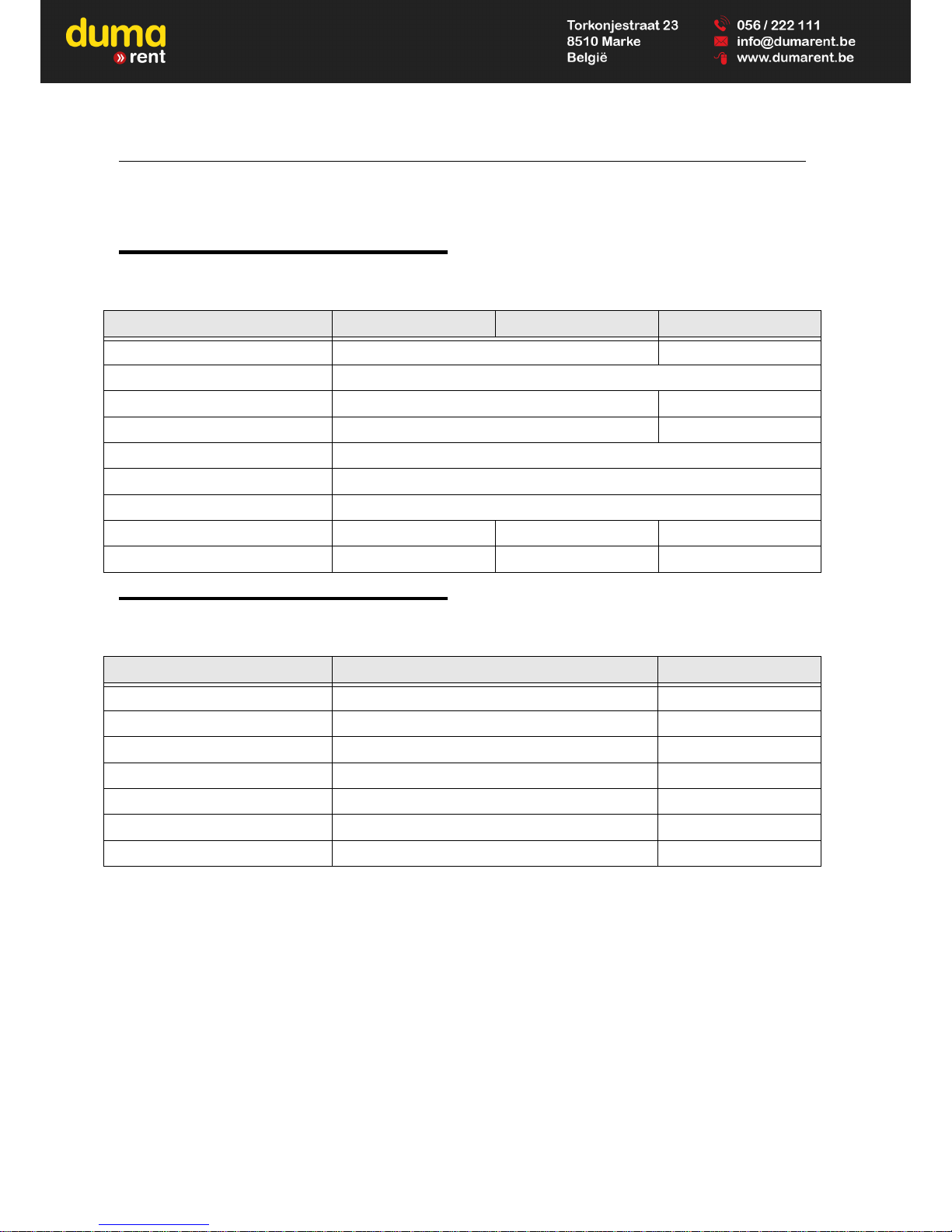
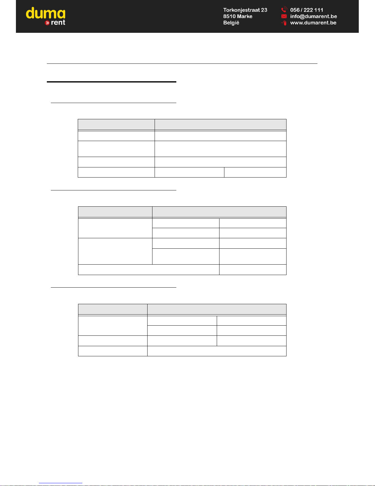
Table 1-1. Operating Specifications
Description Model Toucan 12E Model Toucan 12E Plus Model Toucan 32E
Maximum Work Load 200 kg 500 lbs
Maximum Persons 2
Maximum Horizontal Side Force 400 N 100 lbs
Maximum Operating Wind Speed 12.5 m/s (45 km/h) 28 mph
Maximum Stowed Travel Grade (Gradeability) 25% (14°)
Maximum Stowed Travel Grade (Side slope) 8.7% (5°)
Tilt Alarm Triggering Angle Value 3°
Maximum Tire Load (per wheel) 2 280 kg 2 680 kg 5 030 lbs
Approximate Gross Machine Weight - Global 4 300 kg 4 900 kg 9 480 lbs
Table 1-2. Dimensions
Description Models Toucan 12E - Toucan 12E Plus Model Toucan 32E
Overall Stowed Machine Height 1.99 m 6.5’
Overall Machine Length 3.65 m 11.8’
Overall Machine Width 1.20 m 3.9’
Platform Size - Length (Platform base) 0.70 m 27.6"
Platform Size - Width - (Platform base) 1.05 m 41.3"
Wheel Base (Wheels straightened) 1.60 m 5.3’
Ground Clearance (chassis base plate) 10 cm 3.9"
Page 16
SECTION 1 - OPERATING SPECIFICATIONS
1-2 – JLG Lift – 31210149
1.3 PERFORMANCE DATA
1.4 CAPACITIES
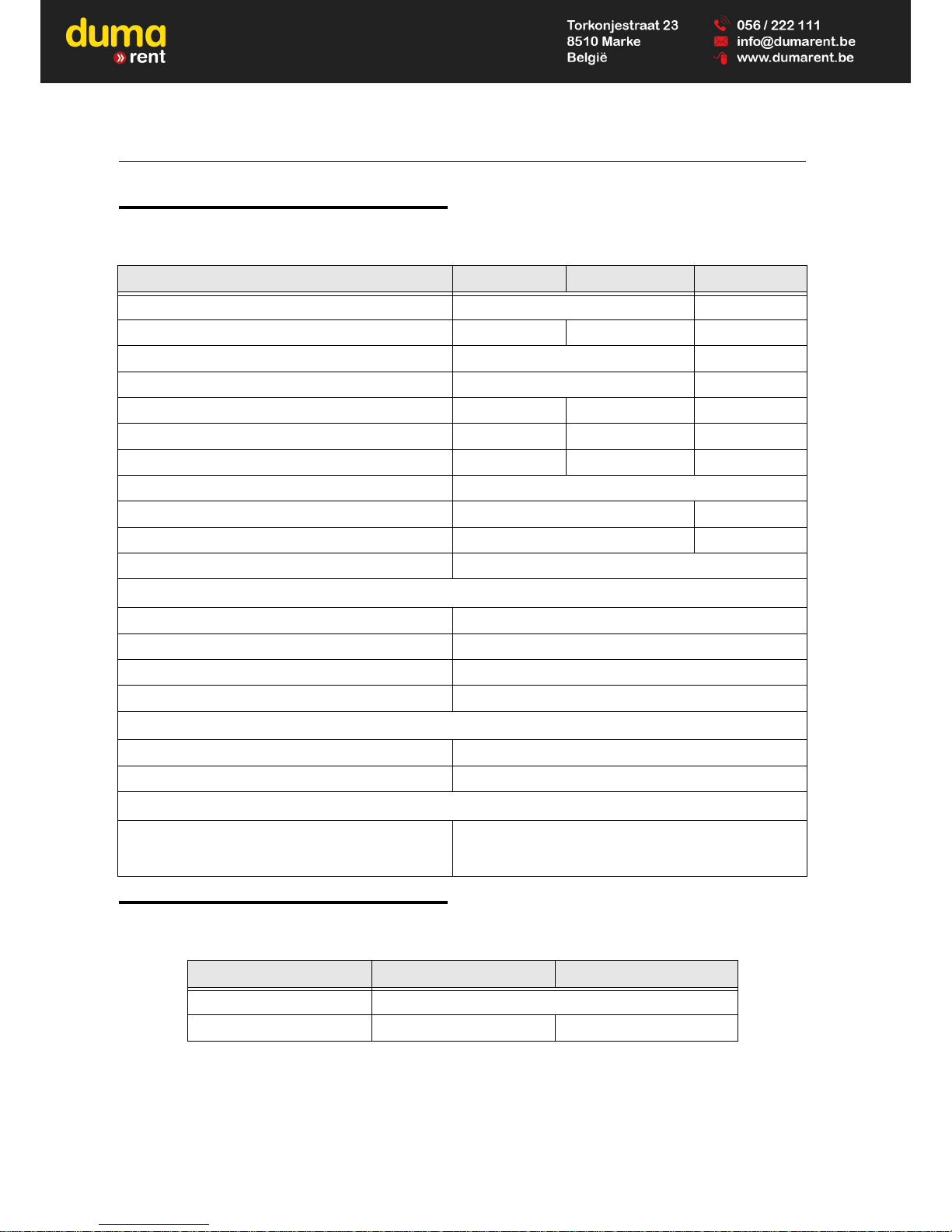
Table 1-3. Performances
Description Model Toucan 12E Model Toucan 12E Plus Model Toucan 32E
Platform Height - Stowed (Platform floor to ground) 0.35 m 1.1 ft
Platform Height - Elevated (Platform floor to ground) 9.83 m 10.65 m 32.3 ft
Platform Height - Mast Elevated / Jib Horizontal (Platform floor to ground ) 7.12 m 23.4 ft
Up and Over clearance - Jib Horizontal 6.95 m 22.8 ft
Maximum Horizontal Reach (from centreline) 4.60 m 5.55 m 14.9 ft
Maximum Horizontal Reach (from side edge of chassis) 4.00 m 4.95 m 13.0 ft
Maximum Horizontal Reach (from rear edge of chassis) 3.57 m 4.52 m 11.5 ft
Swinging Angle 345° (not continuous)
Inside Turning Radius 0.75 m 2.5 ft
Outside Turning Radius 2.60 m 8.5 ft
Gradeability 25% (14°)
Elevating
Mast Lift Up Time - W/one person (approx. 80kg) 22 to 26 seconds
Mast Lift Down Time - W/one person (approx. 80kg) 25 to 29 seconds
Jib Lift Up Time - W/one person (approx. 80k g) 15 to 21 seconds
Jib Lift Down Time - W/one person (Approx. 80kg) 18 to 24 seconds
Swinging
Swinging Time - From rest to rest - Mast stowed 53 to 63 seconds
Swinging Time - From rest to rest - Mast elevated 83 to 99 seconds
Driving
M ax im u m D r iv e S p ee d
Stowed
Ma s t e le v at e d
5.50 km/h
0.75 km/h
Table 1-4. Capacities
Component Models Toucan 12E - Toucan 32E Model Toucan 12E Plus
Hydraulic Tank 15l (11.5 l usable) - 3.96 gal (3.04 gal usable)
Hydraulic System (Including Tank) Approx. 20 l - (5.28 gal) Approx. 21.5 l - (5.3 gal)
Page 17
SECTION 1 - OPERATING SPECIFICATIONS
31210149 – JLG Lift – 1-3
1.5 COMPONENTS DATA
Batteries
Electric Pump / Electric Motor Assembly
Drive Motor Assembly
Table 1-5. Battery Specifications
Description Model Toucan 12E - Toucan 12E Plus - Toucan 32E
Voltage (48VSystem - Series) 8 Packs of 6 Volts (semitraction)
Amp Hour (Standard battery) 260 Amp Hour @ 20 HR. Rate
215 Amp Hour @ 5 HR. Rate
Life Cycle Rating 800 Cycles
Weight - Approx 265 kg 584 lbs
Table 1-6. Hydraulic Unit Specifications
Description Model Toucan 12E - Toucan 12E Plus - Toucan 32E
Motor
Voltage 48 VDC
Powe r 3 .5 kW
Pump (Gear pump)
Displacement 4.2 cc/rev (0.26 cu.in/rev)
Flow rate
11.5 l/mn @ 13 MPa
(3.84 gal/mn@1900 psi)
Max. Operating Pressure 18 MPa (2 600 psi)
Table 1-7. Drive Motor Specifications
Description Model Toucan 12E - Toucan 12E Plus - Toucan 32E
Motor
Vol tage 48 VDC
Power 3.5 kW
Brake Supply Voltage 24 VDC (Nominal)
Sensor Bearing 64 Impulses per rev.
Page 18

SECTION 1 - OPERATING SPECIFICATIONS
1-4 – JLG Lift – 31210149
Swing Drive
Platform Rotation Drive
Cylinders
Tires
Table 1-8. Swing Drive Specifications
Description Model Toucan 12E - Toucan 12E Plus - Toucan 32E
Motor Type Orbital
Displacement 20 cc
Gear Reducer Wheel and Worm. Ratio 1/50
Table 1-9. Platform Rotation Drive Specifications
Description Model Toucan 12E - Toucan 12E Plus - Toucan 32E
Electrical Cylinder
Vol tage 48 VDC
Stroke 150 mm
Table 1-10. Cylinders Specifications
Description Bore DIA. Stroke Rod DIA.
Steer Cylinder (Double Action) 50 mm (1.97 in) 171 mm (6.73 in) 25 mm (0.98 in)
Telescope Cylinder Toucan 12E
(Double Action)
50 mm (1.97 in) 1240 mm (48.82 in) 30 mm (1.18 in)
Telescope Cylinder Toucan 12E Plus
(Double Action)
50 mm (1.97 in) 171 mm (6.73 in) 25 mm (0.98 in)
Master Cylinder (Double Action) 55 mm (2.16 in) 265.5 mm (10.45 in) 35 mm (1.38 in)
Slave Cylinder (Double Action) 55 mm (2.16 in) 265.5 mm (10.45 in) 35 mm (1.38 in)
Mast Cylinder (Single Action) 90 mm (3.54 in) 1005 mm (39.57 in) 80 mm (3.15 in)
Jib Cylinder (Single Action) 70 mm (2.76 in) 755 mm (29.72 in) 65 mm (2.56 in)
Table 1-11. Tires Specifications
Description Models Toucan 12E/12E Plus Tou ca n 3 2E
Size 457 x 178 mm 18 x 7 in
Max. Allowable Tire Load 3 265 kg 7 200 lbs
Wheel Bolt Torque
250 Nm 185 ft lb
210 Nm 155 ft lb
Page 19
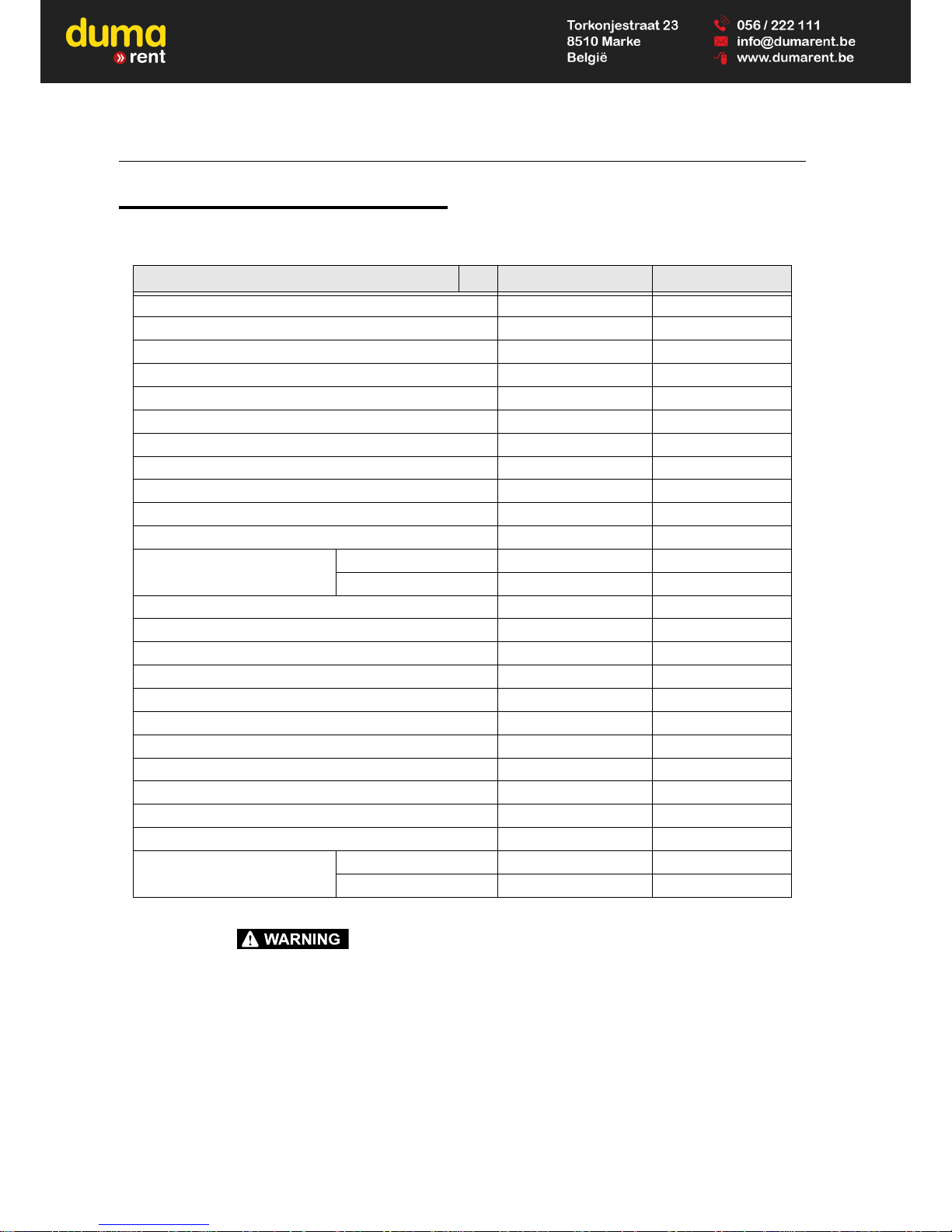
SECTION 1 - OPERATING SPECIFICATIONS
31210149 – JLG Lift – 1-5
1.6 MAJOR COMPONENTS WEIGHTS
DO NOT REPLACE ITEMS CRITICAL TO STABILITY, SUCH AS BATTERIES OR SOLID TIRES, WITH ITEMS OF DIFFERENT WEIGHT OR
SPECIFICATION. DO NOT MODIFY UNIT IN ANY WAY TO AFFECT STABILITY.
Table 1-12. Major Components Weights
Description Models Toucan 12E/12E Plus Tou ca n 3 2E
Platform (*) 54 kg 119 lbs
Platform Support (Without Rotation) 20 kg 44 lbs
Platform Support (Option Rotation) 11 kg 24 lbs
Level Correction Support (Option Rotatio n) 15 kg 33 lbs
Boom 54 kg 119 lbs
Telescope Mid Sec tion (Toucan 12E Plus) 28 kg 62 lbs
Telescope Inner Secti on (Toucan12E Plus) 22 kg 49 lbs
Telescope (Toucan 12E / Toucan 32E) 32 kg 71 lbs
Boom Cylinder 46 kg 101 lbs
Master Cylinder 11 kg 24 lbs
Slave Cylinder 12 kg 26 lbs
Telescope Cyl inder Toucan 12E Pl us 42 kg 93 lbs
Toucan 12E/Toucan 32E 26 kg 57 lbs
Mast Assembly (5 Mast Sections) 630 kg 1 390 lbs
Mast Cylinder 76 kg 168 lbs
Mast Section #1 290 kg 640 lbs
Swing Bearing 32 kg 71 lbs
Swing Drive 17 kg 37 lbs
Electric Pump 18 kg 40 lbs
Chassis 680 kg 1 500 lbs
Wheel and Tire (each) (*) 35 kg 77 lbs
Spindle Steering (each) (*) 19 kg 42 lbs
Drive Motor (each) (*) 90 kg 200 lbs
Battery Standard (each) (*) 33 kg 73 lbs
Counterweight Main (*) 1 395 kg 3 076 lbs
Additional (*) 575 kg 1 268 lbs
(*) Items critical for stability
Page 20

SECTION 1 - OPERATING SPECIFICATIONS
1-6 – JLG Lift – 31210149
1.7 LUBRICATION
Hydraulic Oil
NOTE: Hydraulic oils must have anti-wear qualities and suffi-
cient chemical stability for mobile hydraulic system
service. It is not advisable to mix oil of different
brands or types, as they may not contain the same
required additive or be of comparable viscosities.
Table 1-13. Hydraulic Oil Specifications (Standard)
Specifications NERVOFLUID 15
ISO Viscosity Grade 15
Cinematic Viscosity @ -20°C [-4°F] 213.6 mm²/s (cSt)
Cinematic Viscosity @ 0°C [32°F] 68.1 mm²/s (cSt)
Cinematic Viscosity @ +40°C [104°F] 15.1 mm²/s (cSt)
Pour Point, Max. -40°C (-40°F)
Flash Point, Min. 175°C (347°F)
Viscosity Index 153
ISO 6743-4 Classification HV
Page 21

SECTION 1 - OPERATING SPECIFICATIONS
31210149 – JLG Lift – 1-7
Lubrication Chart
Figure 1-1. Lubrication Chart
NOTE: Lubrication intervals are based on machine operation under normal condition. For machines used in multi shift opera-
tions and/or exposed to hostile environments or conditions, lubrication frequencies must be increased accordingly.
NOTE: Refer to the corresponding sections in this manual for specific lubrication procedures.
Table 1-14. Lubrication Chart
Component
Number/Type
Lube Points
Lube
Interval Hours
Comments
125 250 1000
1 Swing Bearing Race 2 grease fittings A X
2 Swing Bearing Teeth By brush B X Remove old grease first
3 Lifting Chains
Spray on or by
brush
C X Lubricate before first 50 hours of operation
4 Hydraulic Oil
Fill through
reservoir cap
D X Check level daily. Change at least ever y 2 years
1. Swing bearing race
2. Swing bearing Teeth
3. Lifting Chains
4. Hydraulic Oil
Page 22
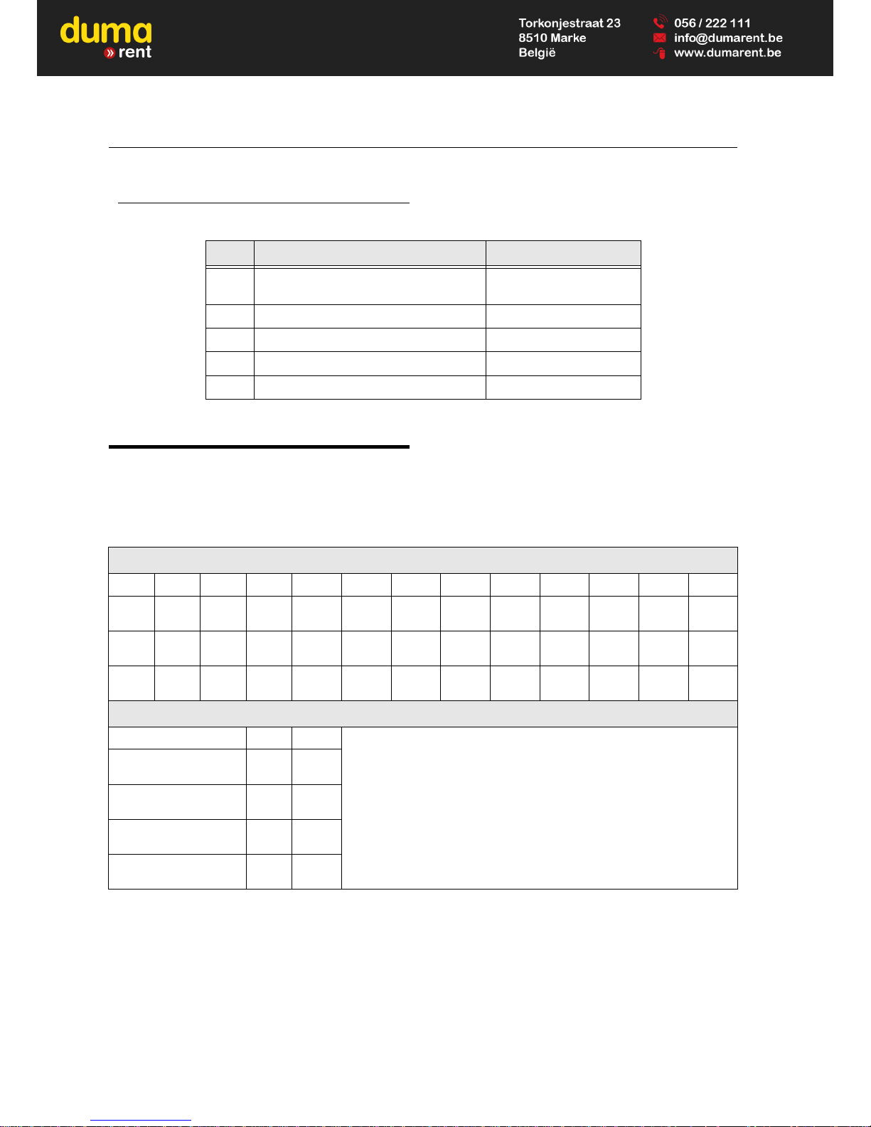
SECTION 1 - OPERATING SPECIFICATIONS
1-8 – JLG Lift – 31210149
Lube Specifications
1.8 TORQUE REQUIREMENTS
Unless specific torque requirements are given within the
text, refer to the following torque chart to determine
proper torque values.
Table 1-15. Lube Specifications
Key Specifications E.g.
A Extreme Pressure - Multi Purpose Grease
MOBILUX EP2
COMPLEX EP2
B Open Gear Lube MOBILTAC 81
C Non Detergent Mineral Oil (*) MOBIL DTE 16M
D Hydraulic Oil NERVOFLUID 15
E Synthetic Chain Oil FUCHS VT800
(*) To be adapted to the machi ne’s operating conditions. Refer to the corresponding section in this manual.
Table 1-16. Torque Chart
Torque Values for Bolts, Nuts and Studs
Grade Unit M4x70 M5x80 M6x100 M8x125 M10x150 M12x175 M14x200 M16x200 M20x250 M24x300 M30x350
8.8
Nm
lbf.ft
2.7
2
5.2
3.8
9.1
6.7
22
16.2
44
32.5
76
56
121
89.2
189
139
370
272
637
469
1280
944
10.9
Nm
lbf.ft
3.9
2.9
7.7
5.7
13.4
9.9
32
23.6
64
47.2
111
81.9
178
131
278
205
544
408
936
690
1880
1386
12.9
Nm
lbf.ft
4.6
3.4
9
6.6
15.7
11.6
38
28
75
55.3
130
95.9
209
154
325
239
637
469
1095
807
2200
1622
Torque Values for Hydraulic Fittings
Ty pe Unit Torque
JIC 9/16"-18
Nm
lbf.ft3022.1
BSPP 1/4"-19
Nm
lbf.ft
14.8
109
BSPP 3/8"-19
Nm
lbf.ft3425.1
Metric M18x150
Nm
lbf.ft5137.6
Page 23
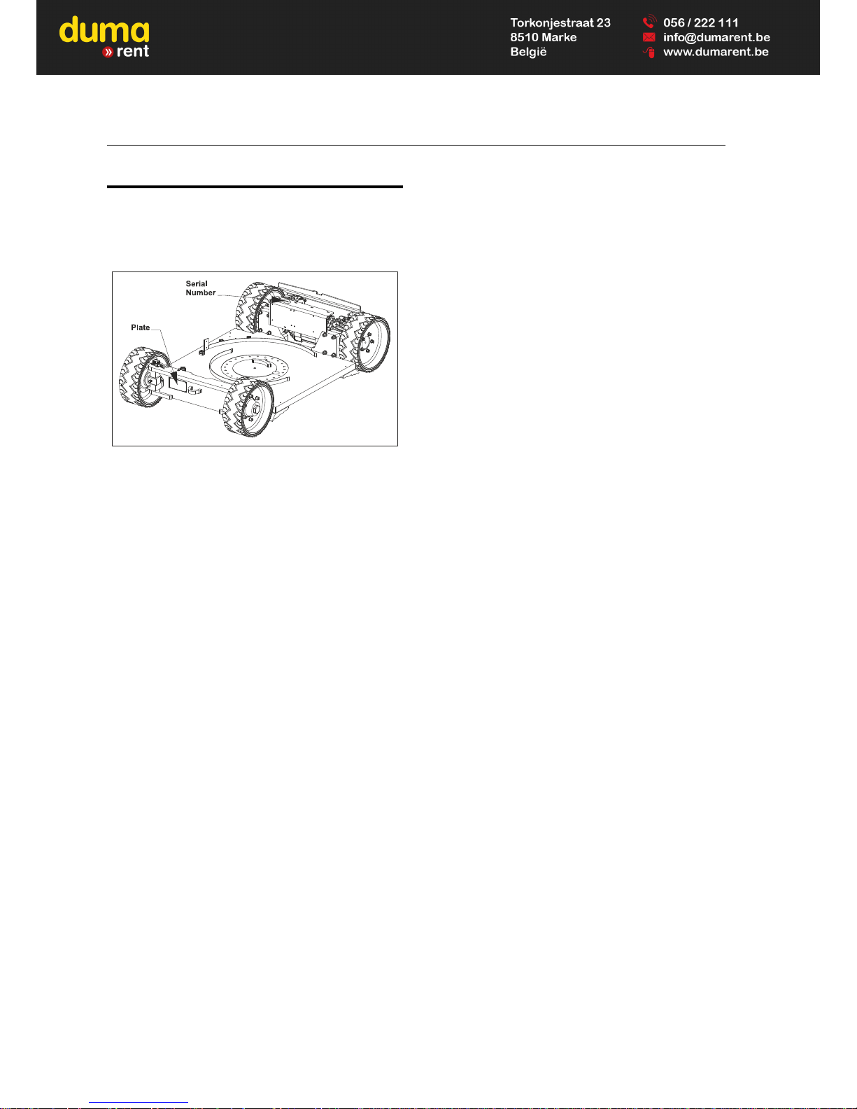
SECTION 1 - OPERATING SPECIFICATIONS
31210149 – JLG Lift – 1-9
1.9 SERIAL NUMBER LOCATIONS
For machines identification, a serial number plate is
affixed at the front side of the chassis. If the serial number
plate is damaged or missing, the machine serial number is
stamped on the frame at location shown following.
Figure 1-2. Serial Number
Page 24

SECTION 1 - OPERATING SPECIFICATIONS
1-10 – JLG Lift – 31210149
NOTES:
_______________________________________ _______________________________________
_______________________________________ _______________________________________
_______________________________________ _______________________________________
_______________________________________ _______________________________________
_______________________________________ _______________________________________
_______________________________________ _______________________________________
_______________________________________ _______________________________________
_______________________________________ _______________________________________
_______________________________________ _______________________________________
_______________________________________ _______________________________________
_______________________________________ _______________________________________
_______________________________________ _______________________________________
_______________________________________ _______________________________________
_______________________________________ _______________________________________
_______________________________________ _______________________________________
_______________________________________ _______________________________________
_______________________________________ _______________________________________
_______________________________________ _______________________________________
_______________________________________ _______________________________________
_______________________________________ _______________________________________
_______________________________________ _______________________________________
_______________________________________ _______________________________________
_______________________________________ _______________________________________
_______________________________________ _______________________________________
_______________________________________ _______________________________________
_______________________________________ _______________________________________
_______________________________________ _______________________________________
_______________________________________ _______________________________________
_______________________________________ _______________________________________
_______________________________________ _______________________________________
_______________________________________ _______________________________________
Page 25
SECTION 2 - GENERAL SERVICE INFORMATION
31210149 – JLG Lift – 2-1
SECTION 2. GENERAL SERVICE INFORMATION
2.1 MACHINE PREPARATION, INSPECTION
AND MAINTENANCE
General
This section provides the necessary information needed
by those personnel that are responsible to place the
machine in operation readiness and maintain its safe
operating condition. For maximum service life and safe
operation, ensure that all the necessary inspections and
maintenance have been completed before placing the
machine into service.
Preparation, Inspection and Maintenance
It is important to establish and conform to a comprehensive inspection and preventive maintenance program. The
following table outlines the periodic machine inspections
and maintenance recommended by JLG Industries, Inc.
Consult your national, regional, or local regulations for further requirements for aerial work platforms. The frequency
of inspections and maintenance must be increased as
environment, severity and frequency of usage requires.
Pre-Start Inspection
It is the User's or Operator's primary responsibility to perform a Pre-Start Inspection of the machine prior to use
daily or at each change of operator. Reference the Operation and Safety Manual for completion procedures for the
Pre-Start Inspection. The Operator and Safety Manual
must be read in its entirety and understood prior to performing the Pre-Start Inspection.
Pre-Delivery Inspection and Frequent
Inspection
The Pre-Delivery Inspection and Frequent Inspection shall
be performed by a qualified JLG equipment mechanic.
JLG Industries, Inc. recognizes a qualified JLG equipment
mechanic as a person who, by possession of a recognized degree, certificate, extensive knowledge, training, or
experience, has successfully demonstrated the ability and
proficiency to service, repair, and maintain the subject
JLG product model.
The Pre-Delivery Inspection and Frequent Inspection procedures are performed in the same manner, but at different times. The Pre-Delivery Inspection shall be performed
prior to each sale, lease, or rental delivery. The Frequent
Inspection shall be accomplished for each machine in service for 3 months or 150 hours (whichever comes first);
out of service for a period of more than 3 months; or when
purchased used. The frequency of this inspection must be
increased as environment, severity and frequency of
usage requires.
Reference the JLG Pre-Delivery and Frequent Inspection
Form and the Inspection and Preventative Maintenance
Schedule for items requiring inspection during the perfor-
mance of these inspections. Reference the appropriate
areas of this manual for servicing and maintenance procedures.
Annual Machine Inspection
The annual machine inspection must be performed by a
Factory-Trained Service Technician on an annual basis, lo
later than thirteen (13) months from the date of the prior
Annual Machine Inspection. JLG Industries, Inc. recognizes a Factory-Trained Service Technician as a person
who has successfully completed the JLG Service Training
School for the subject JLG product model. Reference the
machine Service and Maintenance Manual and appropriate JLG inspection form for performance of this inspection.
Reference the JLG Annual Machine Inspection Form and
the Inspection and Preventative Maintenance Schedule for
items requiring inspection during the performance of this
inspection. Reference the appropriate areas of this manual for servicing and maintenance procedures.
For the purpose of receiving safety-related bulletins, it is
important that JLG Industries, Inc. has updated ownership
information for each machine. When performing each
Annual Machine Inspection, notify JLG Industries, Inc. of
the current machine ownership.
Preventative Maintenance
In conjunction with the specified inspections, maintenance shall be performed by a qualified JLG equipment
mechanic. JLG Industries, Inc. recognizes a qualified JLG
equipment mechanic as a person who, by possession of a
recognized degree, certificate, extensive knowledge, training, or experience, has successfully demonstrated the
ability and proficiency to service, repair, and maintain the
subject JLG product model.
Reference the Preventive Maintenance and Inspection
Schedule and the appropriate areas of this manual for servicing and maintenance procedures. The frequency of
service and maintenance must be increased as environment, severity and frequency of usage requires.
Page 26

SECTION 2 - GENERAL SERVICE INFORMATION
2-2 – JLG Lift – 31210149
2.2 PREVENTIVE MAINTENANCE AND
INSPECTION SCHEDULE
The preventive maintenance and inspection checks are
listed and defined in Table 2-2. This table is divided into
two basic parts, the "AREA" to be inspected and the
"INTERVAL" at which the inspection is to take place. Under
the "AREA" portion of the table, the various systems along
with the components that make up that system are listed.
The "INTERVAL" portion of the table is divided into six columns representing the various inspection time periods.
The numbers listed within the interval column represent
the applicable inspection code for which that component
is to be checked.
The checks and services listed in this schedule are not
intended to replace any local or regional regulations that
may pertain to this type of equipment nor should the lists
be considered as all inclusive. Variances in interval times
may occur due to climate and/or conditions and depending on the location and use of the machine.
Table 2-1. Maintenance and Inspection Requirements
TYPE FREQUENCY
PRIMARY
RESPONSIBILITY
SERVICE
QUALIFICATION
REFERENCE
Pre-start Inspection
Prior to use each day; or
At each Operator change
User or Operator User or Operator Operator and Safety manual
Pre-delivery Inspection
Prior to each sale, lease or
rental delivery
Owner, Dealer or
User
Qualified JLG
Mechanic
Service and Maintenance
Manual and applicable JLG
inspection form
Frequent Inspection
In service for 3 months; or
Out of service for a period of
more than 3 months; or
Purchased used
Owner, Dealer or
User
Qualified JLG
Mechanic
Service and Maintenance
Manual and applicable JLG
inspection form
Annual Machine Inspection
Annually, no later than 13
months from the date of the
prior inspection
Owner, Dealer or
User
Factory-Trained
Service Technician
(Recommended)
Service and Maintenance
Manual and applicable JLG
inspection form
Preventive Maintenance
At intervals as specified in the
Service and Maintenance
manual
Owner, Dealer or
User
Qualified JLG
Mechanic
Service and Maintenance
Manual
Page 27

SECTION 2 - GENERAL SERVICE INFORMATION
31210149 – JLG Lift – 2-3
Table 2-2. Inspection and Preventive Maintenance Schedule
AREA
INTERVAL
Pre-start1
Inspection
Weekly
preventive
maintenance
Monthly
preventive
Maintenance
Pre-delivery2
or Frequent
3
Inspection
Annual4
(Yearly)
Inspection
Every 2
Yea rs
PLATFORM ASSEMBLY
Platform 1-2 1-2
Railing 2 2
Gate 1-5 1-5
Floor 7 2
Lanyard Anchorage Points 2 2-9
Platform Support (Option Platform Rotation
Only)
2 1-2-4 1-2-4
Level Correction Support 2 1-2-4 1-2-4
TELESCOPIC BOOM ASSEMBLY
Boom and Telescope Weldment 2 1-2-4 1-2-4
Pivot Pins and Pins Retainers 1 1-2 1-2
Wear Pads 12 3-12
Hose, Cables Installation, Power Track 1-2-8-11 1-2-8-11
MAST ASSEMBLY
Mast Sections 2 2-4 2-3-4
Roller Pin, Plastic Wear Pad 12 3-12
Pulleys 22
Chains/Yokes 13 12-13 12-13
Hose, Cables Installation, Power Track 1-2-8-11 1-2-8-11
TURNTABLE
Swing Drive System 5 8 5-8 5-8
Swing Bearing Bolts 14
Hose, Cables Installation, Power Track 1-2-8-11 1-2-8-11
Hoods, Hood Props, Hood Latches 5 1-2-5
CHASSIS ASSEMBLY
Chassis Weldment 4
Tires 1-15 16 15-16-17 15-16-17
Wheel Bolts 1 14 14 14
Steering Spindles Weldments 2-4 2-4
Page 28
SECTION 2 - GENERAL SERVICE INFORMATION
2-4 – JLG Lift – 31210149
Steering Knuckles Thrust Washers 12 12
Steer Components 1
Drive Motor Brakes 7-12
Drive Motor Gearbox 8 8
Hoods, Hood Props 5 1-2-5
FUNCTIONS/CONTROLS
Platform Controls 5-6-9 5-6-9 5-6-9
Ground Controls 5-6-9 5-6-9 5-6-9
Manual/Breakdown Controls 5-9 5-9 5-9
Emergency Stop Switches (Ground & Platform)
555
Functions Limit or Cutout Switch Systems 5 5 5
POWER SYSTEM
Batteries 18 18 1-19
Battery Fluid 10 10
Centralized Filling System 5 5 5-8
Battery Container Draining 22 22
Electrical Connections 1 20 20
Battery Charger 55
HYDRAULIC/ELECTRIC SYSTEM
Hydraulic Power Unit 8 1-8 1-8
Hydraulic Cylinders 8 1-7-8 2 1-2-8 1-2-8
Hydraulic Hoses, Lines and Fittings 8 1-8 11 1-2-8-11 1-2-8-11
Hydraulic Tank/Hydraulic Fluid 10
Hydraulic Fluid Replacement 22
Electrical Connections 1 20 20
Instruments, Switches 5 1 7-15
Lights, Horn 5 5
Electric Motor Brushes (Hyd. Power Unit) 7-12
GENERAL
Operation and Safety manuals in Storage
Box
21 21 21
Table 2-2. Inspection and Preventive Maintenance Schedule
AREA
INTERVAL
Pre-start1
Inspection
Weekly
preventive
maintenance
Monthly
preventive
Maintenance
Pre-delivery2
or Frequent
3
Inspection
Annual4
(Yearly)
Inspection
Every 2
Yea rs
Page 29
SECTION 2 - GENERAL SERVICE INFORMATION
31210149 – JLG Lift – 2-5
Maintenance and Inspection Table Codes:
1. Check for proper and secure installation.
2. Visual inspection for damage, cracks, distortion and
excessive wear.
3. Check for proper adjustment.
4. Check for cracked or broken welds.
5. Operates properly.
6. Returns to neutral or "off" position when released.
7. Clean and free of debris.
8. Check for sign of leakage.
9. Decals installed and legible.
10. Check for proper fluid level.
11. Check for chafing and proper routing.
12. Check for proper tolerances.
13. Properly lubricated.
14. Torqued to proper specification
15. No worn edges, excessive wear or distorted profiles.
16. Properly seated around the rim.
17. Proper and authorized components.
18. State of charge.
19. Check/record acid gravity and tension.
20. No loose connections, corrosion or abrasion.
21. Verify.
22. Perform.
Footnotes:
1
: Prior to use each day; or at each operator change.
2
: Prior to each sale, lease or delivery.
3
: In service for 3 months or 125 hours; or out of service
for 3 months or more; or purchased used.
4
: Annually, not later than 13 months from the date of prior
inspection.
ANSI and EMI Manuals/Handbooks
Installed
21
Capacity Decals Installed, Secure, Legible 21 21 21
All Decals/Placards installed, Secure, Legible
21 21 21
Walk-Around Inspection Performed 21
Annual Machine Inspection Due 21 21
No Unauthorized Modifications or Additions 21 2 1
All Relevant Safety Publications Incorporated
21 21
General Structural Condition and Welds 2-4 2-4
All Fasteners, Pins, Shields and Covers 1-2 1-2
Grease and Lubricate to Specifications 22 22
Function Test of All Systems 21 21 21-22
Paint and Appearance 7 7
Stamp Inspection Date on Mast Section #1 22
Notify JLG of Machine Ownership 22
Table 2-2. Inspection and Preventive Maintenance Schedule
AREA
INTERVAL
Pre-start1
Inspection
Weekly
preventive
maintenance
Monthly
preventive
Maintenance
Pre-delivery2
or Frequent
3
Inspection
Annual4
(Yearly)
Inspection
Every 2
Yea rs
Page 30
SECTION 2 - GENERAL SERVICE INFORMATION
2-6 – JLG Lift – 31210149
2.3 SERVICING AND MAINTENANCE
GUIDELINES
General
The following information is provided to assist you in the
use and application of servicing and maintenance procedures contained in this book.
Safety and Workmanship
Your safety and that of others is the first consideration
when engaging in the maintenance of equipment. Always
be conscious of weight. Never attempt to move heavy
parts without the aid of a mechanical device. Do not allow
heavy object to rest in an unstable position. When raising
a portion of the equipment, ensure that adequate support
is provided.
NEVER WORK UNDER AN ELEVATED PLATFORM UNTIL PLATFORM HAS BEEN SAFELY RESTRAINED FROM ANY MOVEMENT
BY BLOCKING OR OVERHEAD SLING.
Cleanliness
The most important single item in preserving the long service life of a machine is to keep dirt and foreign materials
out of the vital components. Precautions have been taken
to safeguard against this. Shields, covers, seals and filters
are provided to keep the wheel bearings, mast sections
and oil supply clean; however, these items must be maintained on a scheduled basis in order to function properly.
At any time when hydraulic oil lines are disconnected,
clean adjacent areas as well as the openings and fittings
themselves. As soon as a line or component is disconnected, cap or cover all opening to prevent entry of foreign matter.
Contaminants in the hydraulic system will affect operation
and will result in serious damage to components working
parts. Every precaution must be taken to keep hydraulic
oil clean, including reserve oil in storage. If the oil must be
poured from the original container into another, be sure to
clean all contaminants from the service container.
Clean and inspect all parts during servicing or maintenance, and assure that all passages and openings are
unobstructed. Cover all parts to keep them clean. Be sure
all parts are clean before they are installed. New parts
should remain in their containers until they are ready to be
used.
Components Removal and Installation
Use adjustable lifting devices, whenever possible, if
mechanical assistance is required. All slings (chains,
cables, etc.) should be parallel to each other and as near
perpendicular as possible to top of part being lifted.
Should it be necessary to remove a component on an
angle, keep in mind that the capacity of an eyebolt or similar bracket lessens, as the angle between the supporting
structure and the component becomes less than 90
degrees.
If a part resists removal, check to see whether all nuts,
bolts, cables, brackets, wiring, etc. have been removed
and that no adjacent parts are interfering.
Component Disassembly and Reassembly
When disassembling or reassembling a component, complete the procedural steps in sequence. Do not partially
disassemble or assemble one part, then start on another.
Always recheck your work to ensure that nothing has
been overlooked. Do not make any adjustments, other
than those recommended, without obtaining proper
approval.
Pressure-Fit Parts
When assembling pressure-fit parts, use an "anti-seize" or
molybdenum disulfide base compound to lubricate the
mating surface.
Bearings
When a bearing is removed, cover it to keep out dirt and
abrasives. Clean bearings in nonflammable cleaning solvent and allow to drip dry. Compressed air can be used
but do not spin the bearing.
Discard bearing if the races and balls (or rollers) are pitted, scored or burned.
If bearing is found to be serviceable, apply a light coat of
oil and wrap it in clean (waxed) paper. Do not unwrap
reusable or new bearing until they are ready to be
installed.
Lubricate new or used serviceable bearings before installation. When pressing a bearing into a retainer or bore,
apply pressure to the outer race. If the bearing is to be
installed on a shaft, apply pressure to the inner race.
Care and Installation of Teflon Coated
Bushings
Bushings:
No jiffy wheels or reaming of any kind can be used on teflon coated bushings.
Once the coating on the bushing is damaged, it cannot be
used any more and must be replaced.
Pins:
Any rough or damaged surface on a pin will cause the teflon coating of the bushing to be damaged.
All rust or masking residue must be cleaned from the pin
prior to assembly.
Never dry (black colored) "Arcor" treated pins (hot washing, vapor...). This will reduce corrosion resistance property of pin coating.
Bushings and Pin:
1. Coat inside diameter of bushing with specified lubricant prior to pin installation.
Page 31

SECTION 2 - GENERAL SERVICE INFORMATION
31210149 – JLG Lift – 2-7
2. Properly align pin and bushing so that the coating
does not get damaged when installing the pin.
3. Pins have chamfered or rounded end to prevent
damage to the coating of the bushing during pin
installation.
Page 32

SECTION 2 - GENERAL SERVICE INFORMATION
2-8 – JLG Lift – 31210149
Bushing Installation:
1. Use an appropriate driver (soft steel) to insert bushing in its housing.
2. Slightly oil the outside diameter of the bushing to
facilitate insertion.
3. Keep driver, bushing and housing correctly aligned
during assembly.
4. Blocking must be used on parts that will receive two
flange bushings to prevent damage to the lower
bushing flange.
Bolt Usage and Torque Application
NOTICE
SELF LOCKING FASTENERS, SUCH AS NYLON INSERT AND
THREAD DEFORMING LOCKNUTS, ARE NOT INTENDED TO BE
REINSTALLED AFTER REMOVAL.
Use bolts of proper length. A bolt which is too long will
bottom before the head is tight against its related part. If a
bolt if too short, there will not be enough thread area to
engage and hold the part properly. When replacing bolts,
use only those having the same specifications of the original, or one which is equivalent.
Unless specific torque requirements are given within the
text, standard torque values should be used on heat
treated bolts, studs and steel nuts, in accordance with recommended shop practices or the Torque Chart in Section
1 of this Service Manual.
Hydraulic Lines and Electrical Wiring
Clearly mark or tag hydraulic lines and electrical wiring, as
well as their receptacles, when disconnecting or removing
them from the unit. This will assure that they are correctly
reinstalled.
Coat contacts of electrical connectors with silicone dielectric compound (Refer to Section 11).
Always disconnect battery plug (located in the battery
compartment) prior to working on the electrical system.
Hydraulic System
EXERCISE EXTREME CARE AROUND PRESSURIZED HYDRAULIC
SYSTEMS WHILE IN OPERATION OR UNTIL ALL PRESSURE IS
RELEASED.
HIGH PRESSURE OIL COULD PENETRATE SKIN AND CAUSE
INJURIES OR BURNS. LOOSEN FITTINGS OR COMPONENTS
SLOWLY TO ALLOW OIL PRESSURE TO DROP GRADUALLY.
When servicing the hydraulic system, use a container to
collect the oil from hydraulic lines or components and prevent it from spilling on the work platform or on the ground.
NOTE: Used oils and filter cartridges must be disposed of
according to regulation in force.
Before disconnecting a hydraulic line or removing a component, clean fittings and adjacent area. As soon as a line
or component is disconnected, cap or cover all opening
to prevent entry of foreign matter.
Disassemble and reassemble hydraulic parts on clean
work surface. Clean all metal parts with non-flammable
cleaning solvent. Lubricate components, as required, to
aid assembly.
Keep the system clean. Hydraulic system filter should be
replaced at the specified intervals. Examine filter cartridge
for evidence of metal or rubber particles. If evidence of
metal or rubber particles is found, drain and flush the
entire system.
Page 33

SECTION 2 - GENERAL SERVICE INFORMATION
31210149 – JLG Lift – 2-9
Welding on Work Platform
When welding on the work platform, disconnect battery
plug and ALL electronic components. When welding on
the chassis, connect the welder ground wire to the
machine chassis as close as possible to the area being
welded. When welding on the superstructure, connect the
welder ground wire to the machine superstructure as
close as possible to the area being welded. This is to prevent arcing inside the swing bearing, the lifting chains or
the cylinders.
NOTICE
FAILURE TO COMPLY WITH THE ABOVE REQUIREMENTS MAY
RESULT IN COMPONENT DAMAGE (I.E. ELECTRONIC MODULES,
SWING BEARING, COLLECTOR RING, BOOM WIRE ROPES ETC.).
Lubrication
Components and assemblies requiring lubrication and
servicing are shown in Section 1.7. Service applicable
components with the amount, type, and grade of lubricant
are recommended in this manual, at the specified intervals. When recommended lubricants are not available,
consult your local supplier for an equivalent that meets or
exceeds the specifications listed.
Battery
Clean and dry battery top. Ensure all connections are
clean and correctly tight. Coat terminals with a silicone
dielectric compound.
Drain the water that can accumulate at the bottom of the
batteries container. (Refer to Section 8-2).
2.4 LUBRICATION INFORMATION
Hydraulic System
The primary enemy of a hydraulic system is contamination. Contaminants enter the system by various means,
e.g., using inadequate hydraulic oil, allowing moisture,
grease, filings, sealing components, sand, etc., to enter
when performing maintenance, or by permitting the pump
to cavitate due to insufficient system warm-up or leaks in
the pump supply.
The design and manufacturing tolerances of the component working parts are very close, therefore, even the
smallest amount of dirt or foreign matter entering a system
can cause wear or damage to the components and generally results in faulty operation. Every precaution must be
taken to keep hydraulic oil clean, including reserve oil in
storage.
Cloudy oils indicate a high moisture content which permits organic growth, resulting in oxidation or corrosion. If
this condition occurs, the system must be drained,
flushed, and refilled with clean oil.
It is not advisable to mix oils of different brands or types,
as they may not contain the same required additives or be
of comparable viscosities. Good grade mineral oils, with
viscosities suited to the ambient temperatures in which
the machine is operating, are recommended for use.
NOTE: Metal particles may appear in the oil of new
machines due to the wear-in of meshing components.
Lubrication Specifications
Specified lubricants, as recommended by the component
manufacturers, are always the best choice, however,
multi-purpose greases usually have the qualities which
meet a variety of single purpose grease requirements.
Should any question arise regarding the use of greases in
maintenance stock, consult your local supplier for evaluation. Refer to Section 1.7 of this Service Manual for an
explanation of the lubricant key designations appearing in
the Lubrication Chart.
Hydraulic Oil
For best performance, JLG recommends the use of ISO
VG 15 oil with a viscosity of 15.1 cSt at 40 °C. Refer to Section 1.7 of this Service Manual for recommended hydraulic
oils.
Changing Hydraulic Oil
Use of any of the recommended hydraulic oils eliminates
the need for changing the oil on a regular basis. If it is necessary to change the oil, use only those oils meeting or
exceeding the specifications appearing in this manual. If
unable to obtain the same type of oil supplied with the
machine, consult local supplier for assistance in selecting
the proper equivalent. Avoid mixing petroleum and synthetic base oils. JLG Industries recommends changing the
hydraulic oil at least every 2 years.
Use every precaution to keep the hydraulic oil clean. If the
oil must be poured from the original container into
another, be sure to clean all possible contaminants from
the service container.
While the unit is shut down, a good preventive maintenance measure is to make a thorough inspection of all
hydraulic components, lines, fittings, etc., as well as a
functional check of each system, before placing the
machine back in service.
2.5 PRESSURE RELIEF VALVE
Pressure relieving in the hydraulic circuit is achieved by a
proportional electric relief valve installed on the power unit
valve body. The valve is adjusted by an electric input.
Pressure relief values of machine functions can be
checked by connecting a pressure gauge at port "M" on
the hydraulic main manifold.
Before checking pressure relief values, operate the
machine a few minutes to warm the hydraulic oil.
For a correct reading of pressure relief values, the
machine must be operated from the platform console at
maximum speed (max. travel of the joysticks). Read the
Page 34

SECTION 2 - GENERAL SERVICE INFORMATION
2-10 – JLG Lift – 31210149
pressure values when the cylinders are at end of stroke or
when the structure is fully swung either to the left or to the
right. When checking pressure relief value of the swing
function, the mast and jib must be fully lowered.
In case of noisy operation of the pressure relief valve
when cylinders are at end of stroke, bleed the air from the
circuit.
Refer to Sections 7 and 9-8 of this manual for further information.
2.6 HYDRAULIC CARTRIDGE
INSTALLATION
Before install a new cartridge, ensure that no external contaminant is present. Inspect O-rings and back-up rings to
ensure there is no damage such as cuts or nicks.
Lubricate all seals of the cartridge with a small amount of
the same oil that is used on the work platform (Refer to
Section 1-7). If the seals are too dry, the back-up ring
could spin out of the cage groove and cause seal damage.
Insert the cartridge into the cavity and tighten by hand in a
clockwise manner. Continue to screw in the cartridge with
a torque wrench and tighten to the specific torque. It is
important to use the specified torque for each valve to
ensure optimal performance of the cartridge.
Insert the coil and use the specified torque when tightening the coil nut. It is important to use the specified torque
for each coil nut to ensure the stainless steel tube is not
stretched.
If the valve requires two coils, install them separately.
Place the washer on top of first coil then install the second
coil. Finally, install and tighten the coil nut to the specified
torque.
Page 35

SECTION 3 - THEORY OF OPERATION
31210149 – JLG Lift – 3-1
SECTION 3. THEORY OF OPERATION
3.1 OVERVIEW
The control system is composed of four main electronic
modules and a maintenance display.
The Ground Module (UGM), located on the right side of
the turntable, is the master system controller.
Most functions are dispatched and coordinated from this
module, all other system modules handle sub-tasks.
All characterized information (values) are stored into the
UGM (i.e., Personalities, Machine Setups or Calibrations).
If the master module is reprogrammed, this information is
lost. The technician should record Personalities and
Machine Setups before programming so they can be
restored afterwards.
Otherwise, default values can be used as a starting point
to restore previous configuration.
The Master Power Module (MPM) and Slave Power module (SPM), located at the rear of the chassis, are controlled by the Ground Module through a bus CAN.
The Ground Module and the Master and Slave Power
modules enable the control system (UGM controls the
high side of the voting relay, SPM controls the low side of
the voting relay, MPM controls the low side of the main
contactor).
The Master Power Module controls the right drive motor
and its brake and the hydraulic pump motor via commands from the CAN bus. It also measures current
applied to these loads and input voltage for fault protection and reporting.
The Slave Power Module controls the left drive motor and
its brake via commands from the CAN bus. It also measures current applied to these loads and input voltage for
fault protection and reporting.
The PLATFORM MODULE reads linked switches and joysticks positions and relays that information to the UGM.
It uses information from the CAN bus for operator display.
It also reports faults pertaining to devices in the Platform
Control Station and devices connected to the Platform
Control Station.
The Multi Display Indicator (MDI), located at the Ground
Control Station, uses information from the CAN bus for
operator display.
The machine can be fitted with an optional Rotate Module.
This module, located in the platform support, controls the
platform rotate actuator via commands from the CAN bus.
It also measures current applied to the electric motor of
the actuator and input voltage for fault protection and
reporting.
For safe operation of the vehicle, the control system will
not allow certain functions under certain conditions. These
are called interlocks. Specific interlocks are discussed
below. The interlocks discussed assume that all control
system devices are functioning properly unless indicated.
Fault conditions will generate Diagnostic Trouble Codes
and additional interlocks.
Some faults only show up at power-up when the control
system performs a self-test. All controls should be left
alone during this test.
Note that the market and model of the machine affects
what personalities and setups are. The appropriate information is displayed for the given model and market. The
market and model must be set properly for safe and lawful
operation of the machine.
3.2 MODES OF OPERATION
Ground Mode
When the machine is powered up in Ground Mode, only
the functions at the Ground control station are operational. Functions are controlled by membrane switches
(buttons). Whatever the function controlled, the Enable
button [ ] must be pushed-in and held to enable other
controls.
Platform Mode
In platform mode the Platform Control Box is enabled. It is
the primary control station for the vehicle. At power-up, all
indicators illuminate for a lamp check.
3.3 CAN COMMUNICATIONS
The communications between the different modules is
done through two bus CAN.
CAN 1 links the Ground Module to the Platform Module,
the Rotate Module (if installed) and the Multi Display Indicator (MDI).
CAN 2 links the Ground Module to both Master and Slave
Power modules.
CAN (Controller Area Network) is the type of two-wire differential serial communication link used for control of the
vehicle. This type of network has matured since its invention in 1986 and is used extensively in many kinds of
machines.
Two-Wire Differential: The signal meaning is derived from
the difference in voltage between two wires, usually
twisted together in a common "jacket". This jacket can
also contain a shield surrounding the wires inside for
noise protection. Any noise that does penetrate the shield
will affect both wires the same. However, the difference in
voltage stays the same, therefore signal meaning is not
corrupted. This differs from one-wire signals in that one
wire signals derive the signal meaning from the difference
between the signal wire and system ground wire. The system ground is the ground for many signals, as well as
power. Any noise on either wire will change the signal and
may corrupt it.
Serial Communication Link: Modules on the link send
messages digitally, bit by bit along the wires where differ-
Page 36

SECTION 3 - THEORY OF OPERATION
3-2 – JLG Lift – 31210149
ent voltage levels represent a "1" or a "0". The 1's and 0's
are assembled by the receiver according to the protocol
used to determine the messages meaning. Using serial
communication allows two wires to replace many more. It
also allows use of sensor and switch information in multiple places without duplicating those sensors and
switches.
CAN: On a bus, all modules on the bus are connected to
the same wires. A CAN bus could be represented on a
schematic by a long pair of straight lines with multiple
modules connected to them by short pairs of lines. It has
a termination resistor at both ends of the long lines placed
between the two wires. These resistors are approximately
120 . On a JLG aerial work platform, this is typically in
the platform and in the chassis. These resistors may be in
the harness or in the module. A complete CAN circuit
measures approximately 60 between the two wires and
these wires are open to the shield.
Each module on the CAN bus broadcasts its messages
according to a priority assigned to the message. All the
other modules will receive the message and determine if it
is important to them. Typical message traffic is 300 - 500
messages per second. The high bus speed allows all
modules to be constantly updated around 20 times per
second. A CAN network also has error detection and handling for robust communications.
3.4 JOYSTICKS
The joysticks are used to "command" lift, telescope, swing
and drive. Those commands may be modified by the control system based on interlocks and personalities.
The joystick control handle sensors are not simple potentiometers. There is a position sensing element, and signal
conditioning circuitry in them to generate the position signal. They are powered by 5VDC supplied from the platform module. When centered a joystick will output
approximately 2.5VDC. Fully backward or left, it will output
approximately 0.5V DC. Fully forward or right, it will output
approximately 4.5V DC.
On the handle of the drive/swing joystick is the trigger
switch that must be depressed in order to operate those
functions. For the mast, jib and telescope joystick, an
enable button (located on the right hand side of the box)
must be depressed and held. This prevents unintentional
movement.
To pass start-up tests controls must be released and the
joysticks must be centered.
No operation from the platform console is possible until
the joysticks are centered. If one of the enable device is
found triggered at power-up, the emergency stop switch
must be re-cycled to clear the fault.
Joysticks personalities to define the centered position
(where command is 0%), minimum and maximum forward, as well as minimum and maximum reverse can be
altered by performing a calibration of the joysticks.
3.5 TRACTION
The traction or drive system, moves the vehicle along the
ground by electric asynchronous motors.
Each controller is an inverter which transforms the battery
DC voltage in AC voltage, to power the three phases drive
motors. The motors are wired in triangle configuration.
The rotating speed is directly linked to the voltage frequency applied. The voltage supplied to the motor is
modulated below approx. 60 Hz; above 60 Hz, nominal
voltage is applied. The nominal voltage between two
motor phases is approx. 28 Vrms (will vary depending on
battery status and driving conditions). The default frequency range is 0.6Hz to 146 Hz which approximately corresponds to a driving speed of 0km/h to 5.5km/h. The
actual rotating frequency of the motors is measured by
the encoders; for a proper motor operation, the difference
between the actual frequency and the inverter output frequency has to be maintained within few Hz. When a motor
is driving the machine, Inverter Freq.>Encoder Freq.;
when the motor is braking, Inverter Freq.<Encoder Freq..
The tolerance between the frequency applied and the
actual measurement called maximum slip value, is
approx. 15Hz (depends on the speed and on the driving
conditions).
Figure 3-1. Drive Motor Schematic
The parking and emergency brakes are released by the
controllers: voltage is approx. 24V at driving start (for 1
second) and approx. 16V after.
Page 37

SECTION 3 - THEORY OF OPERATION
31210149 – JLG Lift – 3-3
3.6 PUMP/STRUCTURE MOVEMENTS
An electrically driven hydraulic pump provides hydraulic
pressure to actuate the steering and superstructure movements.
The Power Module is essentially a "low-side" switch for the
pump motor. The positive terminal of the pump is tied to
Battery Positive (+B) after the Line Contactor. The negative terminal of the pump connects to the (-P) Terminal of
the Master Power Module, which switches current through
MOSFET transistors to the Battery Negative.
For variable speed pump operation, the MOSFET transistors switch On and Off at high frequencies. The Duty
Cycle is varied to control the voltage applied to the pump
motor. When the MOSFET's spend 50% of the period On
and 50% Off, approximately half of the available Battery
power will be applied to the pump motor. Similarly, the
MOSFET are On continuously (100% Duty Cycle) to apply
all available Battery power to the pump motor (i.e. Mast
Lift Up at full speed from Platform Mode).
Figure 3-2. Hydraulic Pump Electric Schematic
When the Control System is energized, the voltage at the
(- P) Terminal will be approximately +48V (referenced to B) when the pump is static.
The (-P) Terminal will be approximately at +1V (referenced
to -B) when the pump is running at full speed (i.e. Mast Lift
Up from Platform Mode).
Lift Up/Down
The lift actuators are single acting hydraulic cylinders.
Lift down is "powered" by gravity.
To lift the mast, the pump is run and an appropriate signal
is sent to the proportional relief valve. Then, after a short
delay, the solenoid energizes and opens the mast valve.
The pump speed is set proportional to joystick position.
Fluid flows into the mast cylinder and extend the rod. As
mast sections are linked to each others by lifting chains,
all mast sections elevate simultaneously.
To bring the mast down, appropriate signals are sent for
the proportional relief valve for proper pressure settings
and flow control valve for pre-activation, an the pump is
run for a short period of time to pressurize the circuit.
Once the circuit is pressurized, the mast valve opens.
Then, the flow control valve opens proportional to joystick
position, and allows fluid back to the tank, allowing the
mast to retract by gravity.
Figure 3-3. Mast Lift System - Basic Schematic
Page 38

SECTION 3 - THEORY OF OPERATION
3-4 – JLG Lift – 31210149
To lift the jib, the pump is run and an appropriate signal is
sent to the proportional relief valve. Then after a short
delay, the jib solenoid energizes and opens the jib valve.
The pump speed is set proportional to joystick position.
Fluid flows into the jib cylinder and extend the rod.
To bring the jib down, appropriate signals are sent for the
proportional relief valve for proper pressure settings and
flow control valve for pre-activation, an the pump is run for
a short period of time to pressurize the circuit.
Once the
circuit is pressurized, the jib valve opens. Then, the flow
control valve opens proportional to joystick position, and
allows fluid back to the tank, allowing the jib to go down
by gravity.
Figure 3-4. Jib Lift System - Basic Schematic
Swing
Swing is actuated by a hydraulic motor.
To swing, solenoids of the swing valve energize (right one
to swing to the right and left one to swing to the left), an
appropriate electric signal is sent to the proportional relief
valve and the pump speed is set proportional to joystick
position. Pressure is applied to one port of the motor and
drained from the other, allowing the motor to turn.
Figure 3-5. Swing System - Basic Schematic
Page 39

SECTION 3 - THEORY OF OPERATION
31210149 – JLG Lift – 3-5
Steer
Steering is actuated by a double acting hydraulic cylinder.
To change steering angle of the wheels, pressure is
applied to one side of the piston and drained from the
other.
To steer, solenoids of the steer valve energize (right one to
steer to the right and left one to steer to the left), an appropriate electric signal is sent to the proportional relief valve
and the pump is run.
The pump speed, and thereby the rate of steering angle
change, is adjusted based on drive speed. This adjustment is modified by steer personality settings.
Figure 3-6. Steer System - Basic Schematic
The steering sensor is located on the front steering axle. It
is key operated by the right spindle attach pin. There is a
position sensing element and a signal conditioning circuitry in it to generate the position signal (i.e. the wheel
steering angle). It is powered by 4.3 VDC supplied from
the master power module.
When the wheels are fully steered to the right, is will output approximately 0.7 VDC.
When the wheels are fully steered to the left, it will output
approximately 3.7 VDC.
When the wheels are straight, it will output approximately
2.5 VDC.
Depending on output signal, the speed of the inner drive
motor will be reduced to allow machine to take a curve
(like a differential system).
Te l es c o pe
Telescope movement is activated by a double acting
hydraulic cylinder.
To extend or retract the telescope, solenoids of the telescope valve energize (Tele in to retract and tele out to
extend), an appropriate electric signal is sent to the proportional relief valve and the pump speed is set proportional to joystick position.
Pressure is applied to one side of the piston and drained
from the other.
Figure 3-7. Telescope System - Basic Schematic
Page 40

SECTION 3 - THEORY OF OPERATION
3-6 – JLG Lift – 31210149
Platform Level
Platform level movement is activated by a double acting
hydraulic cylinder.
To level the platform, solenoids of the level valve energize
(the up one to level up and the down one to level down)
and an appropriate electric signal is sent to the proportional relief valve.
Pressure is applied to one side of the piston and drained
from the other.
Figure 3-8. Platform Level System - Basic Schematic
Interlocks
Interlocks are system inputs (limit switches, sensors or
internal controller measurement) which affect the system
functions.
NOTE: For more detailed information concerning system
adjustment and operation, refer to section 8 Control
Components.
Overload Switch
The overload switch senses platform load. In order to
avoid false trip, the switch input is delayed.
• The switch must be tripped for more than 1s to consider the platform overloaded.
• The switch must be released for more than 1s to consider the platform not overloaded.
When the platform overloaded:
• All the movements are cut out from both the platform
console and the ground console if the MACHINE
SETUP, LOAD SYSTEM is set to CUTOUT ALL;
• All the movements are cut out from the platform console if the MACHINE SETUP, LOAD SYSTEM is set to
CUTOUT PLATFORM;
• All the movements can be performed at normal speed
if the MACHINE SETUP, LOAD SYSTEM is set to NOT
INSTALLED;
Tilt Sensor
A dual axis tilt sensor is installed on the chassis.
When the platform is fully lowered (mast and jib switches
NOT tripped), if the machine is tilted:
• A visual alarm is displayed;
• Mast raising is disallowed;
• Jib raising is restricted to travel height (max. platform
floor height approx. 1m (3.3 ft)).
• Other functions are not affected.
When the machine is tilted and above elevation:
• The drive functions are cut-out;
• Telescope out is disallowed;
• Mast Lift Up, Jib Lift Up and Swing are allowed at
reduced speed;
• Mast Lift Down and Telescope In are allowed at normal
speed;
• Jib Lift Down is allowed at normal speed only if mast is
fully lowered;
• Other functions are not affected.
Chain Slack Switches
The chain slack switches sense the lifting chains tension.
In case of slack chain detected:
• The drive functions are cut out;
• Telescope and Swing functions are cut out;
• Jib Lift Down, Mast Lift Down and Platform Level Down
are cut out;
• Mast Lift Up and Jib Lift Up are allowed at reduced
speed;
Drive Orientation Switch
The drive orientation switch is a proximity switch which
trips when the turntable is swung ±45° off center of the
normal driving position. This occurs roughly when the jib
is swung past the rear tires. When the drive orientation
switch is tripped:
• Drive and steer functions can only be performed after
the DOS override switch (on the platform console) has
been engaged. Drive and steer functions can be operated at normal speed;
• All the structure movements remain unaffected by the
DOS.
Page 41

SECTION 3 - THEORY OF OPERATION
31210149 – JLG Lift – 3-7
Mast Limit Switch, Main Jib Limit Switch
The main jib limit switch and the mast limit switch determine if the platform is in Elevated position. When one (at
least) of these switches is tripped:
• Max. driving speed is reduced from approx. 5.5 km/h
to approx. 0.75 km/h.
Secondary Jib Limit Switch (End Of Stroke)
This switch reduces jib up speed and gives a smoother
acceleration ramp (Jib Down) when tripped.
Battery Charger Interlock
When the battery charger is connected to the mains, the
information is sent to the control system. If the battery
charger is connected to the mains:
• All the movements are cut out from the platform console if the MACHINE SETUP, CHARGER INTERLOC is
set to CUTOUT ALL;
• Drive and steer functions are cut out if the MACHINE
SETUP, CHARGER INTERLOC is set to DRIVE ONLY.
Battery Discharge Indication
The battery status is continuously monitored. Indication is
given to the operator through both the MDI and the platform console panel. Functions limitations are applied
depending on three status: charged, discharged (which
corresponds to 70% discharge) and deeply discharged
(which corresponds to 80% discharged).
If the battery is charged, no function limitation is applied.
If the battery is discharged:
• The max. driving speed, in transport position, is
reduced by 50%. Out of transport position, driving
speed is not affected;
• Mast Lift Up and Jib Lift Up maximum speeds are
reduced;
• Other movements can be operated at normal speed.
If the battery is deeply discharged:
• Mast Lift Up, Jib Lift Up and Telescope OUT are cut
out;
• The max. driving speed is limited at 0.4 km/h, whatever
the platform position is;
• Mast Lift Down, Jib Lift Down, Telescope IN and Swing
(If elevated) can be operated at normal speed.
Personality Settings and Calibration
Functions performances may be altered by changing the
applicable personality settings or calibrating different elements of the control system.
Refer to Section 9 of this manual for the applicable procedures.
Page 42

SECTION 3 - THEORY OF OPERATION
3-8 – JLG Lift – 31210149
NOTES:
_______________________________________ _______________________________________
_______________________________________ _______________________________________
_______________________________________ _______________________________________
_______________________________________ _______________________________________
_______________________________________ _______________________________________
_______________________________________ _______________________________________
_______________________________________ _______________________________________
_______________________________________ _______________________________________
_______________________________________ _______________________________________
_______________________________________ _______________________________________
_______________________________________ _______________________________________
_______________________________________ _______________________________________
_______________________________________ _______________________________________
_______________________________________ _______________________________________
_______________________________________ _______________________________________
_______________________________________ _______________________________________
_______________________________________ _______________________________________
_______________________________________ _______________________________________
_______________________________________ _______________________________________
_______________________________________ _______________________________________
_______________________________________ _______________________________________
_______________________________________ _______________________________________
_______________________________________ _______________________________________
_______________________________________ _______________________________________
_______________________________________ _______________________________________
_______________________________________ _______________________________________
_______________________________________ _______________________________________
_______________________________________ _______________________________________
_______________________________________ _______________________________________
_______________________________________ _______________________________________
_______________________________________ _______________________________________
Page 43

SECTION 4 - CHASSIS MOUNTED COMPONENTS
31210149 – JLG Lift – 4-1
SECTION 4. CHASSIS MOUNTED COMPONENTS
4.1 DRIVE MOTORS
The electric wheel drive assemblies are mounted independent of each other on the base frame at the rear of the
machine.
The wheel drive assembly consists of a 28V AC asynchronous electric motor driving a gear box. The assembly also
includes a friction disk parking brake assembly. This
brake assembly is mounted on the end of the drive motor
assembly.
The component parts of the left and right drive motor
assemblies are identical.
Brake - Electrical Characteristics
Coil, nominal voltage: 24 VDC
Coil, resistance: 13.3 ±0.6
Brake - Dust Cleaning
Due to a possible build-up of dust from brake lining wear
inside the brake compartment, it is recommended to perform this dust cleaning task on an annual basis using
clean, oil free, compressed air.
Figure 4-1. Dust Cleaning
1. Disconnect battery plug.
2. Remove chassis hoods.
3. Remove the dust protection ring (1) from the friction
plate retaining groove (2) and pull it over the magnet
body (3).
4. Blow any accumulated dust in brake compartment.
5. Once complete, correctly reposition the dust protection ring.
Brake Disassembly
Figure 4-2. Brake Disassembly
1. Place the machine on a flat and level surface. Using
ground controls fully rotate the turntable either to the
left or to the right. Turn power off and disconnect
battery plug. Chock both front wheels.
2. Remove chassis hoods. Remove chassis rear shield.
3. Disconnect electric cables from brake terminal block
(1).
4. Remove dust protection ring (2) from friction plate
retaining groove (3) and pull it over magnet body (4)
as shown. The protection ring will help to keep all
parts together during brake removal.
5. Loosen the 3 screws (5) securing brake assembly.
6. Remove magnet body and armature plate assembly
(6).
7. Remove brake disk (7) from driver (8). Remove friction plate (3).
Brake Disk Wear Checking
Figure 4-3. Brake Disk Wear Checking
Check brake disk thickness on several locations.
Replace the disk if its thickness is below 8.5mm (0.335
in.).
Page 44

SECTION 4 - CHASSIS MOUNTED COMPONENTS
4-2 – JLG Lift – 31210149
Brake Assembly
NOTE: The brake is only suitable for dry operation. All parts
must be free from grease, oil, water or other substances that could affect braking efficiency.
Figure 4-4. Brake Assembly
1. Insert the 3 screws (1) in the magnet body (2)
mounting holes.
2. Install the 6 springs (3). Locate springs as shown.
3. Install the 3 bushings (4).
4. Install the armature plate (5) taking care to align the
threaded holes of the plate with the through holes of
the magnet body and to position the chamfer
upwards.
5. Install the dust protection ring (6) onto the assembly
to keep all parts in place.
6. Install the friction plate (7) on the motor assembly.
7. Install the brake disk (8) on the driver (9).
8. Reposition the friction plate (7) so as the mounting
screws will go through the holes that are nearing the
slots.
9. Install and secure the brake assembly.
10. Correctly position the dust protection ring (6). Install
the dust cap (10).
Drive Motor Assembly Removal
Figure 4-5. Drive Motor Removal
1- Drive Motor Assembly
2- Hardened washer
3- Spring Washer
4- Socket Head Cap Screw (Grade 10.9)
1. Place the machine on a flat and level surface. Using
ground controls fully rotate the turntable either to the
left or to the right. Turn power off and disconnect
battery plug. Chock both front wheels.
2. Remove chassis hoods. Remove rear and side
shields.
3. Using a jack of appropriate capacity, elevate the
machine enough to be able to remove the wheel(s)
and to place blocks under the chassis.
4. Remove the wheel(s).
5. Disconnect sensor bearing/thermal sensor connector and brake supply cables. Tag and disconnect
motor cables from the controller.
6. Attach an adequate lifting device to the drive motor
assembly and remove slack.
7. Loosen hardware securing the motor assembly to
the chassis. Remove the drive motor assembly.
Page 45

SECTION 4 - CHASSIS MOUNTED COMPONENTS
31210149 – JLG Lift – 4-3
Drive Motor Assembly Installation
Install drive motor assembly in reverse order from
removal. Ensure the tenon of the gear box casing contacts
the top of the mounting plate slot as shown following.
Figure 4-6. Drive Motor Installation
Correctly install the hardened washers and spring washers. Torque the 4 Hex. Head Cap Screws Grade 10.9 to
102 Nm (75 ft.lb).
Oil Type & Capacity
The torque hub unit is designed to utilize the same oil
throughout its service life. However, should it need to be
serviced the oil could need to be drained and replaced.
When serviced, fill the unit with ISO VG220 oil.
The gearbox will need to be filled with 2 liters (0.53 Gal.) of
oil.
Oil Filling
Gearbox oil filling is performed through the filling port as
shown in figure 4-6, until oil level is flush with the threads
(gearbox in horizontal position).
Figure 4-7. Oil filling
Page 46

SECTION 4 - CHASSIS MOUNTED COMPONENTS
4-4 – JLG Lift – 31210149
4.2 WHEELS AND TIRES
Tire Wear and Damage
Inspect tires periodically for wear or damage. Tires with
worn edges or distorted profiles require replacement.
Tires with significant damage in the tread area or side wall,
require immediate evaluation before replacing machine
into service.
Wheel and Tire Replacement
Replacement wheels must have the same diameter and
profile as the original. Replacement tires must be the
same size and rating as the tire being replaced.
Use of genuine parts is recommended.
Both tires/wheel on the same axle must be replaced:
• If the overall diameter of the tire is less than 445 mm.
• If any uneven wear is discovered.
A tire with significant damage in the tread area or sidewall requires immediate evaluation before placing the
machine into service. If a cut, tear, chunk, or other discrepancy exceeds any one or more of the following
dimensions, the tire must be replaced:
76 mm long, 19 mm wide, 19 mm deep
• If the metal wheel is visible at any point through the
tread area of the tire.
• If more than one discrepancy exists in any quadrant of
the wheel (within 90 degrees of one another).
Wheel Installation
It is extremely important to apply and maintain proper
mounting torque.
WHEEL LUG NUTS MUST BE INSTALLED AND MAINTAINED AT
THE PROPER TORQUE TO PREVENT LOOSE WHEELS, BROKEN
LUG NUTS, AND POSSIBLE SEPARATION OF WHEEL FROM THE
AXLE. BE SURE TO USE ONLY THE LUG NUTS THAT MATCHED TO
THE CONE ANGLE OF THE WHEEL.
Tighten the lug nuts to the proper torque to prevent
wheels from coming loose. Use a torque wrench to tighten
the fasteners. Over-tightening will result in breaking the
lug nuts or permanently deforming the mounting holes in
the wheels. The proper procedure for attaching wheels is
as follow:
1. Start all lug nuts by hand to prevent cross threading. DO NOT use a lubricant on threads or nuts.
2. Tighten lug nuts in the following sequence.
Figure 4-8. Wheel Lug Nut Tightening Sequence
3. The tightening of the lug nuts should be done in
stages. Following the recommended sequence,
tighten lug nut per wheel torque.
4. Wheel lug nuts should be torqued after the first 50
hours of operation and after each wheel removal.
Check torque every 3 month or 125 hours of operation.
Table 4-1. Wheel Torque Chart
Torque Sequence - Front Wheels
1
st
Stage 2nd Stage 3
rd
Stage
50 N.m (37 lb.ft) 160 N.m (118 lb.ft) 250 N.m (184 lb.ft)
Torque Sequence - Rear Wheels
1
st
Stage 2nd Stage 3
rd
Stage
50 N.m (37 lb.ft) 140 N.m (103 lb.ft) 210 N.m (155 lb.ft)
Front Rear
Page 47

SECTION 4 - CHASSIS MOUNTED COMPONENTS
31210149 – JLG Lift – 4-5
4.3 STEERING LINKAGE
Figure 4-9. Steering Linkage Assembly
Steer Cylinder
Removal
1. Tag, disconnect and cap steer cylinder hydraulic
lines and ports.
2. Remove hardware on top of the left link/cyl. anchor
pin (9).
3. Remove the cylinder anchor pin (7).
4. Remove the cylinder.
Inspection
Check cylinder flange bushings and flange bushing
installed onto chassis for damage or excessive wear.
Replace if necessary.
Cylinder Disassembly
Refer to Section 7-8.
Installation
1. Coat bushings inside diameter with multipurpose
grease.
2. Install the rod end onto the left link/cyl. anchor pin
(9) and secure with hardware. Apply Loctite #242 to
screw threads.
3. Align barrel holes with frame mounting hole. Install
cylinder anchor pin and secure with hardware.
4. Remove caps and connect hydraulic lines to cylinder ports.
5. Perform a few steering movements to bleed air from
the circuit and to check for proper operation.
6. Check hydraulic fluid level and adjust accordingly.
Steering Linkage - Spindle/Hub Assembly
Removal
1. Should the spindle(s) require(s) removal, remove
the wheel(s).
2. If necessary, remove steer cylinder (10) as previously described.
3. Remove right link anchor pin (8) and left link/cyl.
anchor pin (9).
4. Remove the steering link (3).
5. If the right spindle/hub assembly requires removal,
remove the steering sensor (4).
6. Loosen locknut and screw securing the spindle pin
(5-6) and remove the pin. Remove the spindle (1)
and the thrust washer (2).
Inspection
Check bushings installed on the chassis axle for damage
or excessive wear. Replace if necessary.
Check bushings installed on the steering link for damage
or excessive wear. Replace if necessary.
Check pins condition. Replace if necessary.
Check thrust washer thickness. Replace washer if its
thickness is less than 5mm (0.20 in.).
Installation
1. Coat chassis axle bushings inside diameter with
multipurpose grease.
2. Install thrust washer (2) and spindle/hub assembly
(1) between the two plates of the axle. Insert spindle
pivot pin (insert right spindle pin (5) so as the blind
1. Spindle/Hub assembly
2. Thrust washer
3. Link
4. Steer Sensor
5. Right Spindle Pin (Sensor Drive)
6. Left Spindle Pin
7. Cylinder Anchor Pin
8. Right Link Anchor Pin
9. Left Link/Cyl. Anchor Pin
10. Hydraulic Steer Cylinder
Page 48

SECTION 4 - CHASSIS MOUNTED COMPONENTS
4-6 – JLG Lift – 31210149
radial hole of the pin aligns with the threaded hole of
the spindle) and secure with hardware.
3. Coat steering link flange bushings inside diameter
with multipurpose grease.
4. Install the steering link (3) with flanges downwards.
Install anchor pins and secure with hardware.
5. Install steering sensor as shown following.
Figure 4-10. Steering Sensor Installation
6. Install steer cylinder if removed.
7. Install wheels: Refer to Section 4-2.
NOTICE
IF STEERING SENSOR WAS REMOVED/REPLACED, OR SENSOR
DRIVING PIN AND/OR SPINDLE WAS REMOVED/REPLACED, IT IS
HIGHLY RECOMMENDED TO PERFORM A STEERING SENSOR
CALIBRATION PROCEDURE. REFER TO SECTION 9-5.
Page 49

SECTION 5 - TURNTABLE AND VERTICAL MAST
31210149 – JLG Lift – 5-1
SECTION 5. TURNTABLE AND VERTICAL MAST
5.1 SWING BEARING
Swing Bearing Attach Bolts Check
This check must be performed after the first 50 hours of
machine operation and every 500 hours of machine operation thereafter. If during this check, bolts are found missing or loose, replace missing or loosen bolts (use
Loctite® 270 on bolts installed in threaded holes through
swing bearing outer race).
Outer bearing race is attached to the chassis plate.
Inner bearing race is attached to the turntable base plate.
1. Place the machine on a flat and level surface. Fully
lower the mast and the jib. Remove chassis hoods
and chassis side shields.
2. Using a suitable overhead lifting equipment attached
to both lifting rings of mast section #1, lift and place
the machine on blocks of a minimum height of
500mm (20") and capable of supporting the weight of
the work platform. Position blocks in such a way that
the swing bearing attach bolts to the chassis remain
accessible and that the machine remain stable on
blocks when the structure will be swung.
Figure 5-1. Access Holes
3. Check outer race attach screws in sequence for correct torque condition: torque value 117 Nm (86 ft lbs).
4. Check inner race attach screws and nuts in sequence
for correct torque condition: torque value 117 Nm (86
ft lbs). Attach screws are accessible through an
access hole in the chassis base plate: rotate superstructure using the ground controls (or manual swinging devices) to gain access to each screw.
Figure 5-2. Torque Sequence Diagram
Swing Bearing Lubrication
Bearing Race Lubrication
Lube Points: 2 grease fittings
Capacity: A/R
Lube: A (See Table 1-14)
Interval: Every 250 hours of operation
Figure 5-3. Swing Bearing Race Lubrication
1. From ground control station, raise the mast to gain
access to the turntable base plate.
2. Locate the two access holes (1) on the turntable
plate.
3. Lubricate using a grease gun through the 2 grease
fittings (2).
Bearing Teeth Lubrication
Lube Points: Coat each tooth
Capacity: A/R
Lube: B (See Table 1-14)
Interval: Every 1000 hours of operation
Figure 5-4. Swing Bearing Teeth Lubrication
1. Remove chassis hoods and lateral frame shields.
Inner race
Outer race
HEX. HEAD CAPSCREW M12-90 (18mm A/F)
W/LOCKNUTS (19mm A/F)
HEX. HEAD CAPSCREW M12-70 (18mm A/F)
Page 50

SECTION 5 - TURNTABLE AND VERTICAL MAST
5-2 – JLG Lift – 31210149
2. From ground control station, raise the mast to gain
access to the turntable plate.
3. Fully swing the structure to the right.
4. Apply grease on the accessible bearing teeth
using a brush (1).
5. Fully swing the structure to the left.
6. Complete the operation on the rest of bearing
teeth.
Replacement of Swing Bearing
Removal
Figure 5-5. Swing Bearing Removal - 1 of 6
1. Using a suitable overhead lifting equipment
attached to both lifting rings of mast section #1, lift
and place the machine on a support (1) with a minimum eight of 500 mm (20") and capable of supporting the weight of work platform.
NOTE: Toucan 12E/32E weight : 4300 kg / 9480 lbs
Toucan 12E Plus weight : 4900 kg / 10800 lbs.
Position the frame such a way that the swing bearing
attach bolts under the chassis remain accessible (2).
Let the machine secured with the lifting device.
NOTE: During the lift up operation, the tilt angle will be
about 9° for the Toucan 12E and 7° for the Toucan
12E Plus, in the platform direction.
Figure 5-6. Swing Bearing Removal - 2 of 6
2. Remove chassis hoods and lateral frame shields.
3. Tag and disconnect power cables from the bottom
battery packs.
4. Remove bottom battery packs (Qty 4) and battery
supports on both side to gain access to the circular
power track (3).
5. Disconnect the power track (3) from the machine
frame (4).
6. Tag and disconnect all the cables and hoses that
come from the power track and that are connected
on frame components (Steering cylinder,
controller,...). Cap or plug all openings so no dirt
enters the system.
7. Disconnect the power track (3) from the machine
turntable (5).
Roll the power track around the turntable and store it
above the swing drive. Secure it with tie straps to
avoid any damages when the turntable will be
removed from the frame.
Figure 5-7. Swing Bearing Removal - 3 of 6
Page 51

SECTION 5 - TURNTABLE AND VERTICAL MAST
31210149 – JLG Lift – 5-3
8. Remove and discard the 24 screws and hardened
washers (6) securing the swing bearing outer race to
the frame.
Figure 5-8. Swing Bearing Removal - 4 of 6
9. Carefully lift the turntable assembly (5) and place it
onto a support (7) with a minimum height of 500 mm
(20") and capable of supporting the weight of the
complete assembly.
NOTE: Toucan 12E/32E turntable weight: 3000 kg/6615 lbs.
Toucan 12E Plus turntable weight: 3600 kg/7940 lbs.
Figure 5-9. Swing Bearing Removal - 5 of 6
Position the turntable such a way that the swing
bearing (8) can be removed.
Let the turntable secured with the lifting device.
NOTE: During the lift up operation, the tilt angle will be
about 8° for the Toucan 12E and 7° for the Toucan
12E Plus, in the platform direction.
Figure 5-10. Swing Bearing Removal - 6 of 6
10. Remove and discard the 24 screws (9) and nuts (10)
securing the bearing (8) to the base plate.
Use a suitable lifting equipment to support and
remove the bearing.
8
8910
Page 52

SECTION 5 - TURNTABLE AND VERTICAL MAST
5-4 – JLG Lift – 31210149
11. Clean and inspect bearing teeth for damages or
excessive wear. Clean bearing seating surfaces on
the chassis and on the turntable base plate. Free
threaded holes on the swing bearing outer race from
dirt, oil or foreign material. Check the functioning of
the ball bearing (cracks or hard points).
Installation of Swing Bearing
JLG INDUSTRIES RECOMMEND THAT ALL REMOVED BEARING
NUTS, BOLTS AND HARDENED WASHER TO BE DISCARDED
AND REPLACED WITH NEW PARTS. SINCE THE SWING BEARING
IS THE ONLY STRUCTURAL LINK BETWEEN THE CHASSIS AND
TURNTABLE, IT IS IMPERATIVE THAT REPLACEMENT HARDWARE MEETS JLG SPECIFICATIONS. USE OF GENUINE JLG
HARDWARE IS HIGHLY RECOMMENDED.
Figure 5-11. Swing Bearing Installation
1. Install the swing bearing (1) in such a way that the
maximum eccentricity point (marked by a colored
spot on 3 teeth) matches with the pinion (2).
Rotate the inner race to align the two inner race
greasers (3) with the two turntable base plate holes
(4).
2. Loosely install the 24 new screws (5) and locknuts
through inner race of bearing and turntable base
plate.
3. Move the bearing towards pinion until contact.
IF COMPRESSED AIR OR ELECTRICALLY OPERATED WRENCH
IS USED FOR TIGHTENING THE BEARING ATTACHMENT BOLTS,
THE TORQUE SETTING ACCURACY OF THE TOOL SHOULD BE
CHECKED PRIOR TO USE.
4. Following the torque sequence diagram (Refer to
Figure 5-2.) tighten the bolts to an initial torque of 80
N.m (59 ft.lbs). Then following the same sequence,
tighten to a final torque of 117 N.m (86 ft.lbs).
5. Carefully lift the turntable assembly and place it onto
the machine frame such a way that the bearing outer
race holes are in line with the frame holes.
6. Apply thread locking component Loctite 270 on
bearing bolts.
7. Install the bearing bolts and hardened washers.
8. Following the torque sequence diagram (Refer to
Figure 5-2.) tighten the bolts to an initial torque of 80
N.m (59 ft.lbs). Then following the same sequence,
tighten to a final torque of 117 N.m (86 ft.lbs).
9. Repeat all the removal steps in reverse order.
10. Perform a few swing movements from the ground
controls to check for proper operation.
11. Record work platform operating time (hourmeter on
ground console).
Turntable bearing bolts torque will have to be verified after the next 50 hours of operation.
5.2 SWING DRIVE
Swing Drive Removal
12. Place the machine on a flat and level surface.
13. Remove chassis hoods and right side frame shield.
14. Using ground controls, rotate the turntable 90° to the
left.
15. Tag, disconnect and cap swing motor hydraulic lines
and ports.
Figure 5-12. Swing Drive Removal
16. Remove the 4 attachments nuts and washers (1)
securing the swing drive (2) on the turntable base
(3).
17. Lift swing drive upwards and remove it from its
mounting hole.
Page 53

SECTION 5 - TURNTABLE AND VERTICAL MAST
31210149 – JLG Lift – 5-5
Swing Drive Disassembly
Figure 5-13. Swing Drive Disassembly - 1 of 3
1. Remove the screws (4) (Qty 8) to open and remove
the gear assembly cover (5).
Figure 5-14. Swing Drive Disassembly - 2 of 3
2. Remove the screws (6) (Qty 4) to disconnect the
motor flange (7) from the cover (5).
3. Remove the screws (8) (Qty 3) to disconnect the
motor (9) from the flange (7).
Figure 5-15. Swing Drive Disassembly - 3 of 3
4. Remove the screw (10) and the pinion (11).
5. Clean and inspect the hydraulic motor and the pinion for damage or excessive wear.
Replace if necessary.
Swing Drive Assembly
1. Coat the bushing (12) with multipurpose grease.
2. Secure the screw (10) with thread locking compound Loctite 243.
3. Repeat all disassembly steps in reverse order.
Swing Drive Installation
1. Repeat all removal steps in reverse order.
2. Secure the nuts (1) with thread locking compound
Loctite 243.
3. Perform a few swing movements from the ground
controls to check for proper operation.
4. Check hydraulic level and adjust accordingly.
5.3 ROLLERS
Inspection
Check roller pin plastic wear pad thickness. Replace roller
pin if the wear pad thickness is less than 3.5 mm (0.13 in).
Removal and Installation
NOTE: Mast rollers can be removed one by one in turn with-
out dismounting the telescopic mast. Fully lower the
mast to remove the upper rollers. Raise the mast as
necessary to gain access to the lower rollers. Mast
sections alignment must be adjusted after rollers
replacement.
Roller Assembly
Figure 5-16. Roller Assembly
Page 54

SECTION 5 - TURNTABLE AND VERTICAL MAST
5-6 – JLG Lift – 31210149
Roller Removal
1. Unscrew and remove the locknut from the roller pin.
2. Unscrew the roller pin to release the plastic wear
pad and free the wear pad as indicated below:
HOLD THE PLASTIC WEAR PAD, THE ROLLER, THEN THE
WASHER TO PREVENT THEM FROM FALLING TO THE BOTTOM
OF THE MAST PROFILE.
Figure 5-17. Roller Removal
Roller Installation
NOTE: If already assembled, use a locknut to free the plas-
tic wear pad, the roller and the washer from the pin:
install the locknut on the pin and tighten it until the
wear pad is released.
Figure 5-18. Roller Installation
1. Partly tighten the pin on the mast section and slide
the washer on the pin.
2. Apply grease to the wear pad so that it sticks to the
mast wall and does not fall to the bottom of the mast
section.
3. Press the wear pad to the mast wall and slide the
roller and the wear pad in line with the pin.
4. Once the roller is in line with the pin, tighten the pin
so that the roller slides onto the pin.
5. Reposition the wear pad in line with the pin then
tighten the pin until the plastic wear pad is fully
inserted.
6. Loosen slightly the pin to prevent the mast from jamming during adjustment. Loosely install the locknut.
7. Repeat operation for the other pin assemblies.
8. Adjust mast transversal play and mast sections
alignment.
Mast Transversal Play/Mast Sections
Alignment
Mast transversal play adjustment could be necessary
when the plastic pad of the roller pins begin to wear.
Mast sections alignment must be adjusted when mast
rollers have been replaced or if pulley(s) show abnormal
flange wear.
THE ALIGNMENT OF THE MAST SECTIONS AND THE ADJUSTMENT OF THE TRANSVERSAL PLAY OF MAST SECTIONS MUST
BE PERFORMED BY TRAINED AND QUALIFIED PERSONNEL.
DO NOT SUPPRESS COMPLETELY THE TRANSVERSAL PLAY:
FOR THE MECHANISM TO WORK, A MINIMUM PLAY IS NECESSARY.
1. Clean the inside walls of the mast sections to
remove old grease.
2. Loosen the locknuts of the roller pins.
3. Reduce the transversal play by tightening the roller
pins in succession.
4. Fully raise the mast and use a plumb line to ensure
the vertical alignment of the mast sections is kept.
Figure 5-19. Mast Sections Vertical Alignment
Page 55

SECTION 5 - TURNTABLE AND VERTICAL MAST
31210149 – JLG Lift – 5-7
5. Tighten the roller pin locknuts (use a slogging
wrench).
6. With the rated load evenly distributed on the platform floor, fully raise and lower the mast two or three
times.
7. If during lowering, one of the mast sections jams,
discontinue lowering and raise the mast to retention
the chains. Loosen slightly the roller pins of the
jammed mast section.
8. Check each roller pin locking nuts for correct tightening.
5.4 LIFTING CHAINS
NEVER WORK UNDER AN ELEVATED PLATFORM UNTIL PLATFORM HAS BEEN SAFELY RESTRAINED FROM ANY MOVEMENT
BY BLOCKING OR OVERHEAD SLING.
Safety Accessories and Tooling
Using suitable lifting equipment to support mast section(s)
during chain replacement procedure is essential for good
working safety condition.
A long hollow body socket is required to allow insertion
over the long threaded chain anchors. A box socket can
be built using a square drive socket and a tube as follow:
Figure 5-20. Long Hollow Body Socket
Use this box socket with a square driver ratchet and
appropriates square drive extensions to reach the anchors
attachment nuts.
Lubrication
Lube Points: 8 chains
Capacity: A/R
Lube: C (See Table 1-14)
Interval: After the first 50 hours of operation and every 125
hours of operation (or every 3 months) thereafter.
THE INITIAL LUBRICATION OF THE CHAINS IS ONLY TO PROTECT THEM AGAINST RUST AND TO PROTECT FRICTION SURFACES DURING THE FIRST 50 HOURS OF OPERATION.
Page 56

SECTION 5 - TURNTABLE AND VERTICAL MAST
5-8 – JLG Lift – 31210149
AVOID REMOVING THE LUBRICANT FROM THE CHAINS. DO NOT
USE ACID OR DETERGENT TO CLEAN THE CHAINS. USE ONLY
SPECIFIED LUBRICANT. NEVER USE GREASE TO LUBRICATE
THE CHAINS.
NOTE: Chains lubrication intervals must be established
depending on the environment in which the work
platform is operated or stored (dusty or aggressive
environment). The lubricant must be adapted to the
machine's operating condition. In general, a non
detergent mineral oil is sufficient. Its viscosity must
be adapted to the temperature according to the
chart below. A too low viscosity will facilitate draining
of the lubricant by gravity. A too high viscosity will
prevent lubricant from reaching the friction surfaces
of the chain.
1. Using the ground control station, fully raise the
mast.
2. Lubricate the chains with a specified lubricant using
a paint brush or by spraying (if using a paint brush,
lubricant must be applied longitudinally to facilitate
penetration of lubricant between friction surfaces,
then transversely between the plates to enable lubricant to reach the joint).
NOTE: If the chains are too clogged for the lubrication to be
correctly performed:
• Remove them from the mast.
• Thoroughly clean them with paraffin oil.
• Dry with compressed air while moving the chain.
• IMMEDIATELY dip in specified lubricant and move the
chain.
• Reinstall chain and cycle the mast several times.
Lifting Chains Inspection
Inspect thoroughly each chain over its entire length:
• Chains, anchors, clevis pins and splits pins should not
be corroded.
• Plates should not be cracked:
Figure 5-21. Cracked Plate
• The plate clevis pins should not present excessive
play.
• Pins should not have turned in their housing (1).
Figure 5-22. Turned Pin
• Plates should not be worn above 5% of their total
height.
Figure 5-23. Worn Plate
• Chains should not have stretched above the values
indicated in the chart below.
All chain appearing faulty or worn must be replaced
including chain anchors. Condition of the pulleys, pulley
bushings and telescopic mast alignment must be
inspected.
Operating Temperature °C (°F) ISO Viscosity grades VG
-15°C to 0°C (5°F to 32°F)
15 to 32 mm²/s (cSt)
0°C to 50°C (32°F to 122°F)
46 to 150 mm²/s (cSt)
4th Stage 3rd Stage
1st and 2nd
Stage
Pitch
5/8" (15.875 mm) 3/4" (19.05 mm)
H min.
11.5 mm
(0.453 in.)
13.6 mm
(0.535 in.)
17.2 mm
(0.68 in)
Pitch
5/8" (15.875 mm) 3/4" (19.05 mm)
L max.
163.5 mm (6.4 in.) 196 mm (7.7 in.)
Page 57

SECTION 5 - TURNTABLE AND VERTICAL MAST
31210149 – JLG Lift – 5-9
Lifting Chains Removal and Installation
Figure 5-24. Chains Stages and Attachments Description
Page 58

SECTION 5 - TURNTABLE AND VERTICAL MAST
5-10 – JLG Lift – 31210149
Figure 5-25. First Chain Stage
Figure 5-26. Second Chain Stage
Page 59

SECTION 5 - TURNTABLE AND VERTICAL MAST
31210149 – JLG Lift – 5-11
Figure 5-27. Third Chain Stage
Figure 5-28. Fourth Chain Stage
Page 60

SECTION 5 - TURNTABLE AND VERTICAL MAST
5-12 – JLG Lift – 31210149
REPLACE SYSTEMATICALLY BOTH CHAINS OF A SAME STAGE. CHAIN ANCHORS, CLEVIS PINS, BEVEL WASHERS AND NUTS MUST
ALSO BE REPLACED. USE ONLY GENUINE JLG PARTS. REMOVE THE LIFTING CHAINS ONE BY ONE. ALWAYS REPLACE AND TENSION
A CHAIN BEFORE REMOVING ANOTHER ONE. IN ADDITION, LIFTING EQUIPMENT SUCH AS CHAINS OR SLINGS SHOULD BE INSTALLED
AS REQUIRED TO SUPPORT MAST SECTIONS DURING CHAIN REMOVAL. CORRECTLY TAG AND DISCARD WORN CHAINS AND COMPONENTS SO THAT THEY CANNOT BE INSTALLED ON THE WORK PLATFORM OR ON ANOTHER MACHINE.
INSTALLATION OF CHAINS MUST BE DONE IN A CLEAN WORK AREA. DO NOT REMOVE THE LUBRICANT FROM THE CHAIN BEFORE,
DURING OR AFTER THEIR INSTALLATION. WHEN UNROLLING OR INSTALLING CHAINS, AVOID TWISTING THEM.
NOTE: As part of the lifting chain replacement procedure, inspect condition of the pulley pins and pulleys. Replace all dam-
aged parts.
Remove frame hoods, frame shields and rotate the turntable 90 degrees to get easier access to the mast assembly.
1
st
Chains Stage Removal
1. Using the ground controls, raise the mast to gain
access to chain attachments #1 and #2.
2. Safely secure mast sections #3, #4 and #5 with
adjustable lifting chains as indicated on the figure
below.
Draw all slack from chains.
Figure 5-29. First Chains Stage Removal
3. Remove the locknut, attachment nut and the bevel
washers from a chain anchor at attachment #2.
4. If installed, remove the chain slack detection assembly from the other end of the chain at attachment
#1.
To remove the detection assembly, first remove the
sensor, the actuator, the spring, the sensor support
and then the attachment nut.
If not installed, remove the locknut and the attachment nut from the other end of the chain.
5. Remove the chains from the pulley groove.
6. Install and tension a new chain before removing the
other one.
1
st
Chains Stage Installation
1. Install the short anchor at one end of the chains.
Correctly install the split pins on the clevis pin.
2. Install the long anchor at the other end of the chain.
Correctly install the clevis pins on the split pin.
3. Run the chain over the pulley. The short anchor
must be on the side of attachment #1.
4. Install the chain slack detection assembly or the
attachment nut and locknut (as indicated on the previous figures) at attachment #1.
5. Install the bevel washers and the attachment nut at
attachment #2.
6. Check that the chain is correctly positioned in the
pulley groove and tighten the attachment nut (on the
long anchor) until the chain is under tension. The
locknut will be installed after chains tension adjustment procedure.
7. After both chains of the stage have been replaced,
adjust lifting chains tension accordingly.
Page 61

SECTION 5 - TURNTABLE AND VERTICAL MAST
31210149 – JLG Lift – 5-13
2nd Chains Stage Removal
1. Using the ground controls, raise the mast to gain
access to chain attachment #3 and #4.
2. Safely secure mast sections #4, #5 and #6 with
adjustable lifting chains as indicated on the figure
below.
Draw all slack from chains.
Figure 5-30. Second Chains Stage Removal
3. Remove the locknut, attachment nut and the bevel
washers from a chain anchor at attachment #3.
4. If installed, remove the chain slack detection assembly from the other end of the chain at attachment
#4.
To remove the detection assembly, first remove the
sensor, the actuator, the spring, the sensor support
and then the attachment nut.
If not installed, remove the locknut and the attachment nut from the other end of the chain.
5. Remove the chain from the pulley groove.
6. Install and tension a new chain before removing the
other one.
2
nd
Chains Stage Installation
1. Install a short anchor at one end of the chain. Correctly install the split pins on the clevis pin.
2. Install the long anchor at the other end of the chain.
Correctly install the split pins on the clevis pin.
3. Run the chain over the pulley. The short anchor
must be on the side of attachment #4.
4. Install the chain slack detection system or the
attachment nut and locknut (as indicated on the previous figures) at attachment #4.
5. Install the bevel washers and attachment nut at
attachment #3.
6. Check that the chain is correctly positioned in the
pulley groove and tighten the attachment nut (on the
long anchor) until the chain is under tension. The
locknut will be installed after chains tension adjustment procedure.
7. After both chains of the stage have been replaced,
adjust lifting chains tension accordingly.
Page 62

SECTION 5 - TURNTABLE AND VERTICAL MAST
5-14 – JLG Lift – 31210149
3rd Chains Stage Removal
1. Using the ground controls, raise the mast to gain
access to chain attachment #5 and #6.
2. Safely secure mast sections #5 and #6 with adjustable lifting chains as indicated on figure below.
Draw all slack from chains.
Figure 5-31. Third Chains Stage Removal
3. Remove the locknut, attachment nut and the bevel
washers from a chain anchor at attachment #6.
4. If installed, remove the chain slack detection assembly from the other end of the chain at attachment #5.
To remove the detection assembly, first remove the
sensor, the actuator, the spring, the sensor support
and then the attachment nut.
If not installed, remove the locknut and the attachment nut from the other end of the chain.
5. Remove one of the chain anchors so that the chain
can be removed from the pulley groove.
6. Install and tension a new chain before removing the
other one.
3
rd
Chains Stage Installation
1. Install a short anchor at one end of the chain. Correctly install the split pins on the clevis pin.
2. Run the end of the chain (without anchor) over the
pulley. The short anchor must be on the side of
attachment #5.
3. Install the long anchor at the other end of the chain.
Correctly install the split pins on the clevis pin.
4. Install the chain slack detection system or the
attachment nut and locknut (as indicated on the previous figures) at attachment #5.
5. Install the bevel washers and attachment nut at
attachment #6.
6. Check that the chain is correctly positioned in the
pulley groove and tighten the attachment nut (on the
long anchor) until the chain is under tension. The
locknut will be installed after chains tension adjustment procedure.
7. After both chains of the stage have been replaced,
adjust lifting chains tension accordingly.
Page 63

SECTION 5 - TURNTABLE AND VERTICAL MAST
31210149 – JLG Lift – 5-15
4th Chains Stage Removal
1. Using the ground controls, raise the mast to gain
access to chain attachment #7 and #8.
2. Safely secure mast section #6 with adjustable lifting
chains as indicated on figure below.
Draw all slack from chains.
Figure 5-32. Fourth Chains Stage Removal
3. Remove the locknut, attachment nut and the bevel
washers from a chain anchor at attachment #7.
4. If installed, remove the chain slack detection assembly from the other end of the chain at attachment
#8.
To remove the detection assembly, first remove the
sensor, the actuator, the spring, the sensor support
and then the attachment nut.
If not installed, remove the locknut and the attachment nut from the other end of the chain.
5. Remove the chain from the pulley.
6. Install and tension a new chain before removing the
other one.
4
th
Chains Stage Installation
1. Install a short anchor and a long one on the chain.
Correctly install the split pins on the clevis pins.
2. Run the chain over the pulley so that the short
anchor is on the side of attachment #8.
3. Install the chain slack detection assembly or the
attachment nut and locknut (as indicated on the previous figure) at attachment #8.
4. Install the bevel washers and attachment nut at
attachment #7.
5. Check that the chain is correctly positioned in the
pulley groove and tighten the attachment nut (on the
long anchor) until the chain is under tension. The
locknut will be installed after chains tension adjustment procedure.
6. After both chains of the stage have been replaced,
adjust lifting chains tension accordingly.
Page 64

SECTION 5 - TURNTABLE AND VERTICAL MAST
5-16 – JLG Lift – 31210149
Chain Tension Adjustment
The lifting of a same stage must have an identical tension.
In addition, the chains must be tensioned so that the mast
sections are aligned (with approx. 80 kg (176 lbs) in the
platform.
Figure 5-33. Chain Tension Adjustment
Chains Tension Control
1. Fully raise the mast then lower it by approximately
50 cm (20 in.).
2. Press on each chain between the pulley and the
chain attachment. Each chain of a same stage must
have the same deflection.
Figure 5-34. Chains Tension Control
Chain Tension Adjustment
1. With the mast fully lowered, check mast sections
alignment for reference.
2. Fully raise the mast then lower it by approximately
50 cm (20 in.).
3. Remove the locking nuts from the long anchor of the
chains to be adjusted.
4. Press on each chain between the pulley and the
chain attachment to estimate chain deflection difference. Tighten the attachment nut on the anchor of
the chain which is too slack or loosen the attachment nut on the anchor of the chain which is too
tight, so as to ensure the final alignment of the mast
sections is kept.
5. Install and tighten the locknut on each anchor.
5.5 PULLEY - PULLEY SUPPORT
Pulley Inspection
1. From ground controls, raise the mast to get pulleys
visible.
2. Check for slantwise pulleys. Replace pulley assembly and check mast sections alignment.
Figure 5-35. Slantwise Pulley
3. Check for iron filings on turntable circular base plate
or on pulley support bottom tube. Presence of iron
filings indicates a severe pin and pulley assembly
wear. Remove the machine from service until the
worn pulley assembly has been replaced. Check
mast sections alignment after pulley replacement.
4. Measure distance between the top edge of the pulley and the top of the pulley support, then the distance between the bottom edge of the pulley and
the bottom of the pulley support. Unequal distances
indicate a severe pin and pulley assembly wear.
Remove the machine from service until the worn pulley assembly has been replaced.
Page 65

SECTION 5 - TURNTABLE AND VERTICAL MAST
31210149 – JLG Lift – 5-17
Figure 5-36. Pulley Assembly Wear
Removal and Installation
REMOVE PULLEY SUPPORTS AND/OR PULLEY ONE BY ONE.
ALWAYS REPLACE AND SECURE A PULLEY SUPPORT AND/OR A
PULLEY BEFORE REMOVING ANOTHER ONE. THE SAME SUITABLE
LIFTING DEVICE USED FOR CHAINS REMOVAL SHOULD BE USED
TO SUPPORT MAST SECTION DURING DISASSEMBLY.
NOTE: Unless the pulley supports need replacing, there is
no need to remove the lifting chains for removing the
pulleys. If the pulley supports need replacing, follow
the lifting chain removal and installation procedure.
Once the chains slackened, only remove the long
anchor to be able to run the chain out of the pulley
support (if necessary).
Remove frame hoods, frame shields and rotate the turntable 90° to get an easier access to the mast assembly.
Pulley Removal
1. Follow the lifting chains removal and installation procedure to secure the appropriate mast section(s).
2. Remove the locknut from a long anchor and loosen
the attachment nut to slacken the chain.
3. Remove the hardware securing the pulley support to
the mast and slide the pulley support out of the
mast.
Figure 5-37. Pulley Support Removal
4. Remove the pulley pin locking hardware and drive
the pin out while holding the pulley.
Pulley Installation
1. Position the chain over the pulley. Align the pulley
with the mounting holes in the pulley support and
install the pin. Secure the pin with hardware.
2. Install and secure the pulley support to the mast.
3. Tighten the attachment nut of the long anchor to tension the chain before removing the other pulley support. The locknut will be installed after chains
tension adjustment procedure.
4. Adjust chains tension accordingly.
Page 66

SECTION 5 - TURNTABLE AND VERTICAL MAST
5-18 – JLG Lift – 31210149
5.6 MAST CYLINDER
Mast Cylinder Removal
1. Place the machine on a flat and level surface.
Remove chassis hoods and lateral frame shields.
Remove battery top hood. Rotate the superstructure
90°.
2. Using the ground controls, fully raise the mast.
Figure 5-38. Mast Cylinder Removal - 1 of 8
3. Install a couple of suitable blockings (1) to support
mast section #2 (2) as indicated.
The blocking must rest on turntable circular base
plate. Secure the blocking with C-clamps (3).
4. Using the ground controls, lower the mast until mast
section #2 rollers (4) rest on blockings.
5. Remove the drive orientation switch (5) to avoid
damages on next steps.
Figure 5-39. Mast Cylinder Removal - 2 of 8
6. Remove one cotter pin (6) from cylinder anchor pin.
Drive the pin (7) out using a suitable drift.
Figure 5-40. Mast Cylinder Removal - 3 of 8
5
Page 67

SECTION 5 - TURNTABLE AND VERTICAL MAST
31210149 – JLG Lift – 5-19
7. Disconnect the mast cylinder hose from port P2 on
manifold (8). Put the hose end into a tank to collect
the oil during the next step.
Figure 5-41. Mast Cylinder Removal - 4 of 8
8. Control the mast lowering by pushing on mast
lowering lever (9) until the cylinder rod (10) is fully
retracted.
Figure 5-42. Mast Cylinder Removal - 5 of 8
9. Once fully retracted, remove mast lowering lever (9).
Disconnect mast cylinder hose from holding valve
(11) and electric line from the valve coil (12).
Figure 5-43. Mast Cylinder Removal - 6 of 8
10. Using suitable lifting equipment, unhook the mast
cylinder from its supports.
Figure 5-44. Mast Cylinder Removal - 7 of 8
Page 68

SECTION 5 - TURNTABLE AND VERTICAL MAST
5-20 – JLG Lift – 31210149
11. Move the mast cylinder out of the masts.
Figure 5-45. Mast Cylinder Removal - 8 of 8
Mast Cylinder Disassembly
Refer to Section 7-8.
Mast Cylinder Installation
1. Position the mast cylinder fully retracted onto the
mast assembly. Install the drive orientation switch.
2. Install mast lowering lever and connect mast cylinder hose on holding valve and electric line on valve
coil.
3. Connect the other end of the mast cylinder hose to
the port P2 on manifold.
4. Using the ground controls, extend the cylinder until
the hole of the rod aligns with the mounting holes of
the mast section #2. Install the anchor pin and the
cotter pin.
5. Using the ground controls fully extend the cylinder
and remove blocking.
6. From the ground controls, perform a few mast raising/lowering movements to bleed the air from the
circuit and to check for proper operation.
7. Check hydraulic fluid level and adjust accordingly.
Install hoods and frame shields.
Page 69

SECTION 5 - TURNTABLE AND VERTICAL MAST
31210149 – JLG Lift – 5-21
5.7 COUNTERWEIGHT
Counterweight Removal
1. Remove all parts above the counterweight.
Figure 5-46. Counterweight Removal - 1 of 2
2. Install an eye bolt M20x2.5 thread (1) as shown.
3. Attach a sling to the eye bolt.
Use an overhead crane and draw off slack from the
sling.
Figure 5-47. Counterweight Removal - 2 of 2
4. Remove the 2 bottom bolts (2).
Loosen the 2 top bolts (3). Do not remove them from
counterweight (4) (it will help for the installation). Lift
up the counterweight and remove it from the turntable (5).
Counterweight Installation
1. Repeat all removal steps in reverse order.
2. Torque the retaining bolts to 350 N.m (260 ft.lbs).
2
3
5
4
Page 70

SECTION 5 - TURNTABLE AND VERTICAL MAST
5-22 – JLG Lift – 31210149
NOTES:
_______________________________________ _______________________________________
_______________________________________ _______________________________________
_______________________________________ _______________________________________
_______________________________________ _______________________________________
_______________________________________ _______________________________________
_______________________________________ _______________________________________
_______________________________________ _______________________________________
_______________________________________ _______________________________________
_______________________________________ _______________________________________
_______________________________________ _______________________________________
_______________________________________ _______________________________________
_______________________________________ _______________________________________
_______________________________________ _______________________________________
_______________________________________ _______________________________________
_______________________________________ _______________________________________
_______________________________________ _______________________________________
_______________________________________ _______________________________________
_______________________________________ _______________________________________
_______________________________________ _______________________________________
_______________________________________ _______________________________________
_______________________________________ _______________________________________
_______________________________________ _______________________________________
_______________________________________ _______________________________________
_______________________________________ _______________________________________
_______________________________________ _______________________________________
_______________________________________ _______________________________________
_______________________________________ _______________________________________
_______________________________________ _______________________________________
_______________________________________ _______________________________________
_______________________________________ _______________________________________
_______________________________________ _______________________________________
Page 71

SECTION 6 - TELESCOPIC BOOM AND PLATFORM
31210149 – JLG Lift – 6-1
SECTION 6. TELESCOPIC BOOM AND PLATFORM
6.1 OVERLAOD SYSTEM
Overload System Verification
Interval - At least every 6 months of operation
1. Turn machine power on at ground control station.
2. Place a 200 kg load evenly distributed on platform
floor.
• No alarm should be triggered.
3. Add weight on platform (additional load not to
exceed 10 kg) until the overload warning is activated.
• RED light indicators at both the ground and the platform control stations blink.
• An audible alarm sounds.
NOTE: Overload alarm actuation is delayed (Approx. 2 sec-
onds).
4. Remove additional load. Apply a slight force on the
platform from the bottom up.
• Alarms stop.
NOTE: Overload alarm stop is delayed (Approx. 1 second).
5. If the overload warning is not activated after the
addition of 10 kg, set overload system as indicated
below before replacing machine into service.
Overload System Setting
Refer to Section 8-2
6.2 PLATFORM
Platform Removal
1. Place the machine on a flat and level surface. Shut
machine down.
2. Attach slings to the platform railings. Use an overhead crane or another lifting equipment, draw all
slack from slings.
Figure 6-1. Platform Removal-Installation
3. Remove clamp securing electric cables to the platform. If fitted: disconnect AC socket and remove the
air line.
4. Remove platform connectors casing cover (1). Disconnect the connector from the platform console.
5. Remove the retaining rings (2). Remove the bearing
pins (3) and the 4 lateral ball bearings (4).
6. Lift and remove the platform assembly (5).
7. Check the ball bearings (4 lateral and 2 front) for
cracks or hard points. Replace bearings if necessary.
Page 72

SECTION 6 - TELESCOPIC BOOM AND PLATFORM
6-2 – JLG Lift – 31210149
Platform Installation
1. If removed, install the 2 front ball bearings on platform support front pins and secure with hardware
(Use Loctite®243).
2. Install platform onto its support. Install lateral ball
bearings, pins and retaining rings.
3. Correctly route cables and secure them with clamps.
Connect platform console connectors in their casing
and install casing cover. Install AC socket and the air
line if fitted.
4. Set over load system. Refer to § 8-2.
6.3 PLATFORM SUPPORTS AND SLAVE
CYLINDER
Platform Supports and Slave Cylinder
Removal
1. Remove the platform: Refer to § 6-2.
Figure 6-2. Platform Support and Slave Cylinder
Removal - 1 of 4
2. Tag and disconnect all electric cables and hoses.
3. Remove all the clamps (1), channel (2) and power
track (3).
Figure 6-3. Platform Rotation Option (If Equipped)
4. Remove electrical cylinder pin (4) and retaining
washers (5).
5. Lift and remove platform support (6).
Page 73

SECTION 6 - TELESCOPIC BOOM AND PLATFORM
31210149 – JLG Lift – 6-3
Figure 6-4. Platform Support and Slave Cylinder
Removal - 2 of 4
6. Secure the level correction support (7) with a sling.
7. Use a special pin (8) (Ø 30 mm length 140 mm) to
drive the pin (9) out of the support. Let this special
pin into the inner section of the telescope to maintain the telescope cylinder rod in place.
Figure 6-5. Platform Support and Slave Cylinder
Removal - 3 of 4
8. Tilt the support to gain access and to remove the
slave cylinder rod pin (10).
Figure 6-6. Platform Support and Slave Cylinder
Removal - 4 of 4
9. Remove the slave cylinder pin (11).
10. Lift and remove the slave cylinder (12).
NOTE: It is not required to remove platform and platform
supports to remove the slave cylinder. To remove
only the slave cylinder, support the platform with a
suitable lifting equipment and remove pins 10 and
11.
Page 74

SECTION 6 - TELESCOPIC BOOM AND PLATFORM
6-4 – JLG Lift – 31210149
Slave Cylinder Disassembly
Refer to Section 7-8.
Platform Supports and Slave Cylinder
Installation
1. Coat inside diameter of bushings with multipurpose
grease prior to installing pins.Check for excessive
wear of the pins. Replace if necessary.
2. Repeat all removal steps in reverse order.
3. Bleed the air from the slave cylinder: Refer to Section 7-6.
4. Perform a few boom movements from the ground
control to check for proper operation.
5. Check hydraulic fluid level and adjust accordingly.
6.4 TELESCOPIC BOOM, BOOM AND
MASTER CYLINDERS
Boom and Cylinders Removal
1. Remove platform and platform supports: Refer to
Sections 6-2 and 6-3.
Figure 6-7. Boom and Cylinder Removal - 1 of 2
2. Secure the boom assembly (1) with a sling.
3. Remove the boom cylinder pin (2) and tilt the boom
cylinder (3) along the mast section.
4. Remove the master cylinder pin (4) and tilt the master cylinder (5) along the mast section.
5. Remove the boom cylinder pin (6) and remove the
boom cylinder (3). (Use a sling and a lifting equipment if necessary).
6. Remove the master cylinder pin (7) and remove the
master cylinder (5).
NOTE: It is not required to remove platform and platform
supports to remove the boom and master cylinders.
To remove boom and master cylinders, support the
boom with a sling and remove the cylinders pins (2),
(4), (6) and (7).
Page 75

SECTION 6 - TELESCOPIC BOOM AND PLATFORM
31210149 – JLG Lift – 6-5
Figure 6-8. Boom and Cylinder Removal - 2 of 2
7. Lift up the boom assembly (1) to the horizontal and
secure it with slings as shown.
8. Remove the boom pin (8) and lift down the boom
assembly.
NOTE: It is not required to remove the boom and master cyl-
inders from the mast to remove the boom assembly.
Boom and Master Cylinders Disassembly
Refer to section 7-8.
Boom Disassembly
Refer to section 6-5.
Boom and Cylinders Installation
1. Coat inside diameter of bushings with multipurpose
grease prior to installing pins.
Check for excessive wear of the pins. Replace if necessary.
2. Repeat all removal step in reverse order.
3. Perform a few boom movements from the ground
control to check for proper operation.
4. Check hydraulic fluid level and adjust accordingly.
6.5 TELESCOPE
6.5.1 Telescope Toucan 12E Plus
Telescope Sections and Cylinder Removal
1. Remove the telescopic boom. Refer to Section 6-4.
Figure 6-9. Telescope and Cylinder Removal - 1of 5
2. Remove the holding valve block (1) from the telescope dual cylinder (2).
Figure 6-10. Telescope and Cylinder Removal - 2 of 5
3. Remove shims (3) and wear pads (4) that are
located on the boom section (5).
Note the location and the amount of shims to aid in
reassembly.
Loosen the lateral screws (6).
Figure 6-11. Telescope and Cylinder Removal - 3 of 5
4. Remove the telescope cylinder pin (7).
5. Secure the mid section (8) with slings and remove it
from the boom section (5).
1
2
6
5
3
4
Page 76

SECTION 6 - TELESCOPIC BOOM AND PLATFORM
6-6 – JLG Lift – 31210149
Figure 6-12. Telescope and Cylinder Removal - 4 of 5
6. Remove the cylinder bracket (9), the telescope cylinder pin (10) and the pin (11) (Refer to step 7 Section
6-3.).
7. Secure the telescope cylinder (2) with slings and
remove it from telescope sections.
Figure 6-13. Telescope and Cylinder Removal - 5 of 5
8. Remove shims (12) and wear pads (13) that are
located on the mid section (8).
Note the location and the amount of shims to aid in
reassembly.
Loosen the lateral screws (14).
9. Secure inner section (15) with slings if necessary
and remove it from mid section (8).
10. Inspect pins, wear pads and bushings for excessive
wear. Replace if necessary.
Telescope Dual Cylinder Disassembly
Refer to Section 7-8.
Telescope Sections and Cylinder Installation
1. Coat inside diameter of bushings with multipurpose
greased prior to installing pins.
2. Repeat all removal steps in reverse order.
NOTE: Apply multipurpose grease on wear pads sliding
faces prior to installing them.
Secure wear pads retaining bolts with thread locking
compound Loctite 243. Torque the retaining bolts to
7.5 N.m (5.5 ft.lbs).
3. Perform a few telescope movements from the
ground control to check for proper operation.
4. Check hydraulic level and adjust accordingly.
6.5.2 Telescope Toucan 12E / Toucan 32E
Telescope Sections and Cylinder Removal
1. Remove telescopic boom.
Refer to section 6-4.
Figure 6-14. Telescope and Cylinder Removal - 1 of 3
2. Remove telescope cylinder pins (1) and (2).
3. Remove the telescope cylinder (3) from telescope
sections.
Figure 6-15. Telescope and Cylinder Removal - 2 of 3
4. Remove shims (4) and wear pads (5) that are
located on the boom section (7).
Note the location and the amount of shims to aid in
reassembly.
Loosen the lateral screws (6).
9
2
11
10
1
2
3
7
6
4
5
Page 77

SECTION 6 - TELESCOPIC BOOM AND PLATFORM
31210149 – JLG Lift – 6-7
Figure 6-16. Telescope and Cylinder Removal - 3 of 3
5. Secure inner section (8) with slings if necessary and
remove it from boom section (7).
6. Inspect pins, wear pads and bushings for excessive
wear.
Replace if necessary.
Telescope Cylinder Disassembly
Refer to section 7-8.
Telescope Sections and Cylinder Installation
1. Coat inside diameter of bushings with multipurpose
grease prior to installing pins.
2. Repeat all removal steps in reverse order.
NOTE: Apply multipurpose grease on wear pads sliding
faces prior to installing them.
Secure wear pads retaining bolt with thread locking
compound Loctite 243.
Torque the retaining bolts to 7.5 N.m (5.5 ft.lbs).
3. Perform a few telescope movements from the
ground control to check for proper operation.
4. Check hydraulic level and adjust accordingly.
Page 78

SECTION 6 - TELESCOPIC BOOM AND PLATFORM
6-8 – JLG Lift – 31210149
NOTES:
____________________________________ ______________________________________
____________________________________ ______________________________________
____________________________________ ______________________________________
____________________________________ ______________________________________
____________________________________ ______________________________________
____________________________________ ______________________________________
____________________________________ ______________________________________
____________________________________ ______________________________________
____________________________________ ______________________________________
____________________________________ ______________________________________
____________________________________ ______________________________________
____________________________________ ______________________________________
____________________________________ ______________________________________
____________________________________ ______________________________________
____________________________________ ______________________________________
____________________________________ ______________________________________
____________________________________ ______________________________________
____________________________________ ______________________________________
____________________________________ ______________________________________
____________________________________ ______________________________________
____________________________________ ______________________________________
____________________________________ ______________________________________
____________________________________ ______________________________________
____________________________________ ______________________________________
____________________________________ ______________________________________
____________________________________ ______________________________________
____________________________________ ______________________________________
____________________________________ ______________________________________
____________________________________ ______________________________________
____________________________________ ______________________________________
____________________________________ ______________________________________
Page 79

SECTION 7 - HYDRAULICS
31210149 – JLG Lift – 7-1
SECTION 7. HYDRAULICS
7.1 HYDRAULIC LINES CONNECTIONS
Figure 7-1. Hydraulic Lines Connections
Page 80

SECTION 7 - HYDRAULICS
7-2 – JLG Lift – 31210149
7.2 HYDRAULIC POWER UNIT
Figure 7-2. Hydraulic Power Unit
1. Electric Motor
2. Valve Body
3. Coupling
4. Pump (Gear pump)
5. Ta nk
6. Proportional Pressure Relief Valve
7. Proportional Valve Coil
8. Seal 1/4"
9. Adapter M1/4" GAZ
10. Check Valve 4.5 bar
11. Check Valve 0.5 bar
12. Filler/Breather Cap
13. Adapter - 1/2"
14. Cap, Oil Level - 1/2"
15. Plug
16. Suction Pipe
17. Return Pipe
18. Plug - 1/2" BSPP
Ports Identification
Figure 7-3. Ports Identification
Port 1: 1/4" GAZ Pressure Outlet
Port 2: 1/4" GAZ Tank
Proportional Pressure Relief Valve
A screw-in, cartridge-style, pilot operated, spool-type
pressure relief valve (Refer to Figure 7-2). It is infinitely
adjusted across a prescribed range using a PWM signal
delivered by the master controller. As a function of the
electrical control signal, the pressure relief valve changes.
Pressure output is inversely proportional to DC current
input.
When a machine function is performed, the valve is controlled with a signal corresponding to the appropriate
relief pressure.
Setting range of the pressure relief valve: 4,1 to 207 bars.
Pressure relief valve: tightening torque = 25.8 to 28.6 N.m
Pressure relief valve coil nut: tightening torque = 5.4 to 6.8 N.m
NOTICE
THE COIL OF THE PROPORTIONAL RELIEF VALVE IS SPECIALLY
DESIGNED FOR PROPORTIONAL CONTROLS APPLICATIONS. DO
NOT INVERT THIS COIL WITH ANOTHER DIRECTIONAL VALVE
COIL. THE VOLTAGE INDICATION ON THE PROPORTIONAL COIL
IS 12 VDC AND ITS RESISTANCE VALUE IS 8.8 .
NOTICE
AFTER REPLACEMENT OF THE PROPORTIONAL RELIEF VALVE
AND/OR THE PROPORTIONAL COIL, ALL PRESSURE RELIEF
VALUES MUST BE CHECKED AND ADJUSTED ACCORDINGLY.
Refer to Section 9-7 for proper proportional relief valve
adjustment procedure.
1
2
Page 81

SECTION 7 - HYDRAULICS
31210149 – JLG Lift – 7-3
Check Valve 0.5 bar
Prevents the return of the oil flow supplied by the hydraulic power unit through the pump, and to revolve motor
counter clockwise.
Tightening torque for the cartridge: 27 N.m
Check Valve 4.5 bar
Prevents draining of hydraulic lines after movements and
maintain a 4.5 bar pressure.
Tightening torque for the valve: 25 N.m
Electric Motor
Dust Cleaning
Due to a possible built-up of dust from brush wear inside
the pump motor cover around the brushes and armature
under heavy usage, it is recommended to perform this
dust cleaning task on an annual basis. Use clean, oil free,
compressed air.
1. Disconnect the battery plug.
2. Remove the protection cover from the motor.
3. Blow any accumulated brush dust around the
brushes and armature commutator.
4. Check brushes for wear, replace if necessary.
5. Once complete, reassemble for operation.
Figure 7-4. Dust Cleaning
Brush Wear Check (Qty 4)
Replace brushes that are worn below their usable length
(23 mm (0.91 in.)), show signs of uneven wear or signs of
overheating, such as discolored brush shunts and brush
springs. Brushes should always be replaced in complete
sets of four. Use identical replacement parts; do not substitute brush grades as the brushes are matched to the
motor type and application to provide the best service.
Substituting brushes of the wrong grade can cause premature commutator failure and excessive brush wear.
Brush Removal
NOTE: No hydraulic power unit connections or hydraulic
need to be disconnected.
1. Disconnect battery plug.
2. Disconnect both power unit motor cables (+ and -).
3. Loosen the four bolts securing the hydraulic power
unit motor. Lift the motor.
Figure 7-5. Moving Hydraulic Power Unit Motor
Figure 7-6. Motor Brushes
4. Remove the protection cover from the motor.
5. Remove the brush terminal screw (1).
6. Lift the spiral spring (2) and remove the brush (3)
from its housing.
7. Repeat previous steps for each brush (Qty: 4).
Page 82

SECTION 7 - HYDRAULICS
7-4 – JLG Lift – 31210149
Brushes Installation
1. Lift the spiral spring (2) and slide the brush (3) into
its housing.
2. Attach the brush terminal end to the terminal post
using the terminal screw (1).
3. Repeat previous steps for each brush.
4. Install the protection cover.
5. Secure the hydraulic power unit to the machine, as
originally installed.
6. Connect battery plug and check for proper operation of the machine.
7.3 HYDRAULIC TANK
Tank Capacity: 11.5 liters (3.04 gallons)
Hydraulic system capacity:
Toucan 12E: approximately 20 liters (5.28 gallons)
Toucan 12E Plus: approximately 21 liters (5.55 gallons)
Oil Level
Oil level should be checked daily. Hydraulic oil should be
changed every 1000 hours of machine operation or at
least every 2 years.
NOTE: Check oil level with the wheels straight.
Figure 7-7. Hydraulic Oil Check
1. Open the access door to the hydraulic power unit
(1).
2. Locate the decal (2) on the tank (3).
3. The oil level in the tank must be within the MIN (minimum) and MAX (maximum) markings (4) of the
decal.
Adding Oil to the System
NOTE: Care should be taken not to introduce any impurities
(dirt, water, etc...) while cap or plug is removed.
1. Wipe all dirt and debris from the filler/breather cap
(5) area.
2. Remove (unscrew) the filler/breather cap (5).
3. Add proper grade of oil by using a clean funnel. Fill
until oil level is between the MIN and MAX markings
(4). Replace the cap.
MAX
MIN
MAX
MIN
2
4
5
123
6
Page 83

SECTION 7 - HYDRAULICS
31210149 – JLG Lift – 7-5
Tank Draining/Cleaning
1. Fully retract the machine (mast, jib, telescope).
2. Place a collecting tank (with a minimum capacity of
15 liters) under the tank (3).
3. Loosen the draining cap (6) and drain the power unit
tank.
4. Loosen four motor screws (7) and remove the hardware securing the tank. Remove the tank.
5. Drain and wipe the tank.
6. Drain and wipe oil strainer and pipes.
7. Install and secure the tank to the power unit.
Figure 7-8. Tank Draining/Cleaning
Ta n k Fi lli n g
1. Remove the filler/breather cap and fill the tank up to
the MAX level marking.
2. Using the ground controls, fully raise and lower the
mast and the jib and then fully extend and retract the
telescope to bleed the air from the circuit.
3. From platform console, fully steer the wheels to the
right.
4. Check hydraulic fluid level and adjust accordingly.
7.4 MAIN MANIFOLD
Hydraulic control for the different structure movements of
the work platform.
Figure 7-9. Main Manifold
Manifold Schematic
Figure 7-10. Manifold Schematic
A:
Check Valve 0.3 bar
Prevents draining of hydraulic lines after structure movements.
Tightening torque for the cartridge: 27 N.m
B:
Check Valve 0.5 bar
Prevents the oil flow supplied by the hand pump from
going to the secondary manifold during operation using
the breakdown controls.
Figure 7-8
6
7
DBM
DD
DG
OD
OG
P
2
M
C
AB
Page 84

SECTION 7 - HYDRAULICS
7-6 – JLG Lift – 31210149
C: Hand Pump
Oil supply to the hydraulic circuit of the work platform when using the breakdown controls for slewing movements.
Figure 7-11. Hand Pump
DBM:
Proportional Flow Control Valve
A solenoid-operated, electrically-variable, pressure-compensated, spool-type, normally closed
when de-energized, proportional flow control valve.
Provide proportional movements for mast and jib
lowering by regulating flow regardless of system
working pressure. With an increasing current
applied to the solenoid (corresponding to the position of the lowering movement joystick), the valve
will increase output flow.
Manual override to allow (by opening valve at max)
the hand pump for breakdown controls.
Tightening torque for the cartridge: 27 N.m
Tightening torque for the coil nut of the cartridge:
6.8 to 9.5 N.m
NOTICE
THE COIL OF THE PROPORTIONAL FLOW CONTROL VALVE IS
SPECIALLY DESIGNED FOR PROPORTIONAL CONTROLS APPLICATIONS. DO NOT INVERT THIS COIL WITH ANOTHER DIRECTIONAL VALVE COIL. THE VOLTAGE INDICATION ON THE
PROPORTIONAL COIL IS 12 VDC AND ITS RESISTANCE VALUE IS
5.4 .
OD-OG/DD-DG Solenoid Valve 4-3
A solenoid-operated, 4 way, 3 positions, direct-acting, spool-type, closed center, screw-in hydraulic
cartridge valve.
Coil Nominal Voltage: 12 VDC
Coil Resistance Value: 9.8
Tightening torque for the cartridge: 27 N.m
Tightening torque for the coil of the cartridge: 6.8
N.m
OD-OG
Slewing movement right and left, with operation of
manual override. To override, push the knurled button to activate right slewing movement, or pull the
knurled button to activate left slewing movement.
DD-DG
Steering movement right and left.
Disassembly:
1. Remove the cartridge nuts holding the coils (OD,
OG, DD DG, DBM) and remove the coils.
2. Remove the cartridge valves.
Inspection:
1. Clean all parts with an appropriate solvent and dry
with compressed air.
2. Check the spool surfaces are not scratched.
3. Check the axial and radial holes on each spool are
not blocked.
NOTE: If the spool is scratched or if the holes are blocked,
the cartridge must be replaced.
Assembly:
NEVER INTERCHANGE CARTRIDGES. ALL COMPONENTS MUST
BE CLEAN BEFORE ASSEMBLY.
1. Check O-rings are present and not damaged on the
cartridge.
2. Install the cartridge in the manifold.
3. Install the coils and torque the nuts to the corresponding tightening torque.
Page 85

SECTION 7 - HYDRAULICS
31210149 – JLG Lift – 7-7
7.5 SECONDARY MANIFOLD
Hydraulic control for jib, telescope and levelling movements of the work platform.
Figure 7-12. Secondary Manifold
Manifold Schematic
Figure 7-13. Secondary Manifold Schematic
A, B: Pressure Relief Valve
Prevents mechanical damages in case of platform levelling hydraulic system is misadjusted. Direct acting relief
valve with an adjustment pressure range of 120-350 bar.
Both pressure relief valve are factory preset (185 bar for A
and 160 bar for B) and cannot be adjusted on the
machine.
Tightening torque for the cartridge: 25 N.m
C: Check Valve 18.3 bar
Secures a minimum pressure in the platform levelling
hydraulic lines and allow a proper working.
Tightening torque for the cartridge: 27 N.m
D: Pilot Operated Check Valve
Prevents draining of platform levelling lines after a jib or a
platform level movement.
This dual pilot operated check valve has a 3:1 pilot ratio
and the check is spring-biased at 1.7 bar to assure holding.
Tightening torque for the cartridge: 27 N.m
E: Check Valve 2.5 bar
Prevents draining of hydraulic lines after telescope or platform levelling movements.
RT-ST/LV-LD: Solenoid Valve 4-3
A solenoid-operated, 4-way, 3-positions, direct acting, spool type,
motor spool, screw in hydraulic cartridge valve.
Coil Nominal Voltage: 12 VDC
Coil Resistance Value: 9.8
Tightening torque for the cartridge: 25.8 to 28.6 N.m
Tightening torque for the coils nut of the cartridge: 5.4 to 6.8 N.m
RT-ST: Telescope movement in and out
LV-L D: Platform levelling movement up and down
Disassembly
1. Remove the cartridge nuts holding the coils (RT, ST,
LV, LD ) and remov e t he coils .
2. Remove the cartridge valves.
Inspection
3. Clean all parts with an appropriate solvent and dry
with compressed air.
4. Check the spool surfaces are not scratched.
5. Check the axial and radial holes on each spool are
not blocked.
NOTE: If the spool is scratched or if the holes are blocked,
the cartridge must be replaced.
Assembly
NEVER INTERCHANGE CARTRIDGES. ALL COMPONENTS MUST
BE CLEAN BEFORE ASSEMBLY.
1. Check O-rings are present and not damaged on the
cartridge.
2. Install the cartridge in the manifold.
3. Install the coils and torque the nuts to the corresponding tightening torque.
E
D
LD
LV
RT
ST
P4
B
A
C
B4
B3
A4
A3
Page 86

SECTION 7 - HYDRAULICS
7-8 – JLG Lift – 31210149
7.6 CYLINDERS HOLDING VALVES
Mast Cylinder Holding Valve
Figure 7-14. Mast Cylinder Holding Valve
- Removal/Installation
Valve Removal
ENSURE THAT THE MAST IS FULLY LOWERED (OR SAFETY SUPPORTED) BEFORE DISMOUNTING THE VALVE.
DISCONNECT BATTERY PLUG UNTIL THE REPAIRS ARE COMPLETED.
1. Remove the mast cylinder, with the holding valve.
Refer to Section 5-7.
2. Unscrew both screws and washers (1) and (2) then
remove the plate (3).
3. Unscrew the valve mounting screw (4) and plug the
cylinder port (3/8" BSPP).
Valve Installation
1. Check presence and condition of the two auto-centralized BS rings. Install the valve onto the cylinder.
Keep the solenoid valve perpendicular to the cylinder and torque the banjo bolt (4) to 70 N.m.
DO NOT OVER-TORQUE THE VALVE BANJO BOLT.
2. Install plate (3) on the cylinder and the manifold then
secure with screws and washers (1) and (2).
3. Install the mast cylinder on the work platform. Refer
to Section 5-7.
4. Perform a few mast raising/lowering movements to
bleed air from the circuit and to check for proper
operation.
5. Check the mast manual descent for proper operation.
6. Check hydraulic fluid level and adjust accordingly.
Figure 7-15. Mast Cylinder Holding Valve
- Schematic/Exploded View
Mast Solenoid Valve (4)
Holds the platform load in the event of hose failure.
A solenoid-operated, 2-way, normally closed, internally piloted,
bidirectional blocking, screw-in hydraulic cartridge valve, with
operation of manual override.
To override, pull the screw at the end of the valve to activate the
mast lower movement.
Coil Nominal Voltage: 12 VDC
Coil Resistance Value: 7.2
Tightening torque for the cartridge: 32.7 to 35.4 N.m
Tightening torque for the coil nut of the cartridge: 6.8 to 9.5 N.m
Flow Regulator (7)
Ensures a constant and limited lowering speed in the
event of hydraulic failure (valves, hoses...).
Jib Cylinder Holding Valve
Figure 7-16. Jib Cylinder Holding Valve
- Removal/Installation
Page 87

SECTION 7 - HYDRAULICS
31210149 – JLG Lift – 7-9
Valve Removal
ENSURE THAT THE JIB IS FULLY LOWERED (OR SAFELY SUPPORTED) BEFORE DISMOUNTING THE VALVE. DISCONNECT
BATTERY PLUG UNTIL THE REPAIRS ARE COMPLETED.
1. Ensure the jib is lowered (or safely supported -
Refer
to Section 5). Turn power off at ground controls. Disconnect battery plug.
2. Tag and disconnect electric line from the solenoid
valve coil.
3. Disconnect and cap the cylinder hydraulic line and
port (1).
4. Unscrew the hardware (2), (3) and (4) securing the
valve protector (5) and remove the protector.
5. Unscrew the valve banjo bolt (7) and plug the cylinder port (3/8" BSPP).
Valve Installation
1. Check presence and condition of the two BS rings.
Install the valve onto the cylinder. Keep the block in
line with the cylinder and torque the banjo bolt (7) to
70 N.m.
DO NOT OVER-TORQUE THE VALVE BANJO BOLT.
2. Install the valve protector on the cylinder and the
manifold then secure with hardware (2), (3) and (4).
3. Remove port plug and hydraulic line cap. Correctly
connect line to valve port.
4. Connect electric line to solenoid valve coil as previously tagged.
5. Connect battery plug.
6. From platform console, perform at least 5 (five) Jib
Up/Down movement (full stroke) to bleed the air
form the circuit and to check for proper operation.
7. Raise the jib to horizontal position and stop. Perform
a Jib Lowering movement. If there is a jerk upwards
before the jib begins to go down, the circuit is not
correctly bled. Perform additional Jib Up/Down
movements (full stroke) and repeat this step until all
air is bled from the circuit.
8. Check hydraulic fluid level and adjust accordingly.
Figure 7-17. Jib Cylinder Holding Valve
- Schematic/Exploded View
1. Por ted Body
2. Banjo Bolt
3. Autocentralizing BS Ring
4. Jib Solenoid Valve
5. Coil 12 VDC
6. Coil Nut
7. Manual Override Boot
8. Flow Regulator 8 l/mn
9. Plug - ¼" BSPP
10. Hose Adapter
Jib Solenoid Valve (4)
Holds the platform load in the event of hose failure.
A solenoid-operated, 2-way, normally closed, internally
piloted, bidirectional blocking, screw-in hydraulic cartridge
valve, with operation of manual override.
To override, pull the screw at the end of the valve to activate
the jib lower movement.
Coil Nominal Voltage: 12 VDC
Coil Resistance Value: 7.2
Tightening torque for the cartridge: 32.7 to 35.4 N.m
Tightening torque for the coil of the cartridge: 6.8 to 9.5 N.m
Flow Regulator (8)
Ensures a constant and limited lowering speed in the
event of hydraulic failure (valves, hoses...).
Page 88

SECTION 7 - HYDRAULICS
7-10 – JLG Lift – 31210149
Telescope Cylinder Holding Valve
Figure 7-18. Telescope Cylinder Holding Valve -
Removal/Installation
Dual Over-center Valve
Allows to hold the load in the event of hose failure and
allows thermal expansion relief of the hydraulic fluid.
Pilot ratio: 4.1:1
Setting of the Counterbalance Valve (c) Rod Side
1. Lower the jib and retract the telescope.
2. Fully tighten the valve setting screw.
3. Place a 200 kg load evenly distributed on the work
platform floor.
4. Slowly loosen the valve setting screw until the telescope starts to extend, then, tighten the screw again
by 3/4 turn. Tighten the locknut.
Setting of the Counterbalance Valve (d) Piston Side
1. Place a 200 kg load evenly distributed on the work
platform.
2. Fully tighten the valve setting screw.
3. Fully raise the jib and extend the telescope by
approximately 50 cm.
4. Slowly loosen the valve setting screw until the telescope starts to retract, then tighten the screw again
by 3/4 turn. Tighten the locknut.
Valve Removal
ENSURE THE TELESCOPE IS FULLY RETRACTED (OR SAFELY
SUPPORTED) BEFORE DISMOUNTING THE VALVE. DISCONNECT
BATTERY PLUG UNTIL THE REPAIRS ARE COMPLETED.
1. Fully lower the jib and retract the telescope completely. Raise the mast and install suitable blockings
to support the end of the telescope. Lower the mast
until the end of the telescope rests on blockings.
Turn power off at ground controls. Disconnect battery plug.
2. Tag, disconnect and cap telescope cylinder hydraulic lines and ports (V
1
and V2).
3. Unscrew four valve mounting screws (a), plug the
cylinder ports and remove the holding valve.
Valve Installation
1. Check presence and position of the two O-rings (b)
and install the valve onto the cylinder. Torque four
screws (a) to 9.1 N.m.
2. Connect hydraulic lines as previously tagged.
3. Connect battery plug. Using ground controls, raise
the mast and remove blockings.
4. Raise jib to horizontal. Perform a few telescope in/
out movements to bleed air form the circuit and to
check for proper operation.
5. Check hydraulic fluid level and adjust accordingly.
Slave Cylinder Holding Valve
Figure 7-19. Slave Cylinder Holding Valve
- Removal/Installation
Dual Over-center Valves
Allows to hold the load in the event of hose failure and
allows thermal expansion relief of the hydraulic fluid.
Pilot ratio: 7.5:1
Page 89

SECTION 7 - HYDRAULICS
31210149 – JLG Lift – 7-11
Setting of the Counterbalance Valve (c) Rod Side
This valve is factory preset and cannot be adjusted on the
machine.
Adjustment checking: h=12 mm
Figure 7-20. Adjustment Checking
Setting of the Counterbalance Valve (d) Piston Side
1. Fully tighten the valve setting screw.
2. Machine fully retracted, place a 200 kg load evenly
distributed on the work platform.
3. Slowly loosen the valve setting screw until the platform starts to move down, then tighten the screw
again by 1/8 turn. Tighten the locknut.
Valve Removal
ENSURE THE PLATFORM IS SAFELY SUPPORTED BEFORE DISMOUNTING THE VALVE. DISCONNECT BATTERY PLUG UNTIL
THE REPAIRS ARE COMPLETED.
1. Fully retract the machine and ensure work platform
is horizontal. Install suitable blockings to support the
platform. Turn the power off at ground controls and
disconnect battery plug.
2. Tag, disconnect and cap slave cylinder hydraulic
lines and ports (V
1
and V2).
3. Unscrew four valve mounting screws (a), plug the
cylinder ports and remove the holding valve.
Valve Installation
1. Check presence and position of the two O-rings (b)
and install the valve onto the cylinder. Torque four
screws (a) to 9.1 N.m.
2. Connect hydraulic lines as previously tagged.
3. Connect battery plug. Using ground controls, raise
the mast and remove blockings.
4. Perform a few jib raising/lowering movements to
check for proper operation then bleed air from the
circuit (on the cylinder sides).
5. Check hydraulic fluid level and adjust accordingly.
Air Bleeding from Rod Side
Figure 7-21. Air Bleeding From Rod Side
1. Raise the jib to the horizontal position, then fully
retract the slave cylinder (platform level down movement).
2. While levelling the platform down, loosen the bleeding screw (a) by half a turn max.
DURING THE BLEEDING PROCESS, HYDRAULIC OIL IS UNDER
PRESSURE IN THE CYLINDER AND OIL PROJECTIONS CAN HAPPEN.
3. The bleeding process is complete once no more air
escapes from the screw (a). Tighten the bleeding
screw.
4. Clean all parts with a solvant and dry with compressed air.
5. Perform a few platform level up/down movements to
check for proper operation.
6. Check hydraulic fluid level and adjust accordingly.
Page 90

SECTION 7 - HYDRAULICS
7-12 – JLG Lift – 31210149
Air Bleeding from Piston Side
Figure 7-22. Air Bleeding From Piston Side
1. Lower the jib, then fully extend the slave cylinder
(platform level up movement).
2. While levelling the platform up, loosen the bleeding
screw (a) by half a turn max.
DURING THE BLEEDING PROCESS, HYDRAULIC OIL IS UNDER
PRESSURE IN THE CYLINDER AND OIL PROJECTIONS CAN HAPPEN.
3. The bleeding process is complete once no more air
escapes from the screw (a). Tighten the bleeding
screw.
4. Clean all parts with a solvant and dry with compressed air.
5. Perform a few platform level up/down movements to
check for proper operation.
6. Check hydraulic fluid level and adjust accordingly.
7.7 SWING MOTOR
NOTE: Refer to Section 5 of this manual for swing motor
removal procedure.
Figure 7-23. Swing Motor
Ports Identification
Port A: Swing Right
Port B: Swing Left
Page 91

SECTION 7 - HYDRAULICS
31210149 – JLG Lift – 7-13
7.8 CYLINDER REPAIR
NOTE: The following are general procedures that apply to
all the cylinders of the machine. Procedures that
apply to a specific cylinder will be so noted.
NOTE: After cylinder removal, it is recommended to replace
bushings (if fitted). Refer to
Section 2 for bushings
installation procedure.
Figure 7-24. Steer Cylinder
Figure 7-25. Master Cylinder
1. Barrel
2. Rod
3. Gland (Tightening torque:
300 N.m)
4. Piston
5. O-Ring
6. Split Back Up Ring
7. Piston Angled Guide
8. Lock Screw (Tightening
torque: 140 N.m)
9. Wiper Seal
10. Rod Guide
11. O-Ring
12. O-Ring
13. Flange Bushing
1. Barrel
2. Rod
3. Gland (Tightening torque: 300 N.m)
4. Piston
5. O-Ring
6. Split Back Up Ring
7. Piston Angled Guide
8. Lock Screw (Tightening
torque: 240 N.m)
9. Wiper Seal
10. Rod Guide
11. Split Back Up Ring
12. O-Ring
13. O-Ring
14. Draining Screw
15. Drawing Screw Seal
16. Flange Bushing
Page 92

SECTION 7 - HYDRAULICS
7-14 – JLG Lift – 31210149
Figure 7-26. Slave Cylinder
Figure 7-27. Jib Cylinder
1. Barrel
2. Rod
3. Gland (Tightening torque: 300 N.m)
4. Piston
5. O-Ring
6. Split Back Up Ring
7. Piston Angled Guide
8. Lock Screw (Tightening
torque: 240 N.m)
9. Wiper Seal
10. Rod Guide
11. Split Back Up Ring
12. O-Ring
13. O-Ring
14. Draining Screw
15. Drawing Screw Seal
16. Flange Bushing
1. Barrel
2. Rod
3. Gland (Tightening
torque: 300 N.m)
4. Snap Ring
5. Rod Guide
6. Wiper Seal
7. Rod Guide
8. O-Ring
9. O-Ring + Back Up Ring
10. O-Ring
11. Flange Bushing
Page 93

SECTION 7 - HYDRAULICS
31210149 – JLG Lift – 7-15
Figure 7-28. Mast Cylinder
Figure 7-29. Telescope Cylinder
1. Barrel
2. Rod
3. Gland (Tightening
torque: 450 N.m)
4. Snap Ring
5. Rod Guide
6. Wiper Seal
7. Rod Guide
8. Back Up Ring
9. O-Ring + Back Up Ring
10. O-Ring
1. Barrel
2. Rod
3. Gland (Tightening torque: 300
N.m)
4. Piston
5. Spacer
6. O-Ring
7. O-Ring
8. Rod Guide
9. O-Ring
10. Lock Screw (Tightening
torque: 130 N.m)
11. Wiper Seal
12. Rod Guide
13. Back Up Ring
14. O-Ring
15. O-Ring
16. Flange Bushing
Page 94

SECTION 7 - HYDRAULICS
7-16 – JLG Lift – 31210149
Figure 7-30. Telescope Plus Cylinder
1. Barrel
2. Rod #1
3. Rod #2
4. Intermediate Tube
5. Gland (Tightening
torque: 300 N.m)
6. Piston Rod #1
7. Piston Rod #2 (Tightening
torque: 120 N.m)
8. Spacer
9. O-Ring
10. O-Ring
11. Rod Guide
12. O-Ring
13. Lock Screw (Tightening
torque: 130 N.m)
14. Wiper Seal
15. Rod Guide
16. Back Up Ring
17. O-Ring
18. O-Ring
19. Lock Screw (Tightening torque: 5
N.m)
20. Centering
21. O-Ring
22. Centering
23. O-Ring
24. Flange Bushing
Page 95

SECTION 7 - HYDRAULICS
31210149 – JLG Lift – 7-17
Disassembly
NOTICE
NEVER USE COMPRESSED AIR TO EXTRACT THE ROD FROM
THE BATTEL OR TO CYCLE THE CYLINDER.
NOTICE
DISASSEMBLY OF A CYLINDER SHOULD BE PERFORMED ON A
CLEAN WORK SURFACE IN A DIRT FREE WORK AREA.
NOTICE
IF USING A VISE TO HOLD CYLINDER BARREL, NEVER CLAMP
THE BARREL TUBE WITH THE VISE’S JAWS.
1. Drain oil from the cylinder.
2. Place the cylinder barrel into a suitable holding fixture.
3. Using an appropriate tool (C-Wrench), loosen the
barrel head gland by turning it in counter-clockwise
direction.
4. Withdraw the rod assembly from the barrel taking
care not to damage the chrome surface of the
rod(s).
5. All cylinder but mast and jib cylinders: place the rod
assembly into a suitable holding fixture.
6. All cylinder but mast and jib cylinders: loosen the
piston attachment screw. Remove piston parts and
withdraw barrel head gland from the rod.
Mast and Jib Cylinders: remove the rod guide (No
need for removing the snap ring from the cylinder
rod). Withdraw barrel head gland from the rod.
7. Remove and discard seals, O-rings, back-up rings
and guide bands from the piston and the barrel
head gland.
8. Align discarded seals and rings in the order of disassembly as reminder for new seals and rings installation.
Inspection
1. Clean all parts thoroughly with an approved cleaning solvent.
2. Inspect the cylinder rod for scoring, tapering, ovality
or other damage. If necessary, dress rod with
Scotch Brite or equivalent. Replace cylinder if necessary.
3. Inspect threaded portion of the rod for excessive
damage. Dress threads as necessary.
4. Inspect the inner surface of the cylinder barrel tube
for scoring or other damage. Check inside diameter
for tapering or ovality. Replace cylinder if necessary.
5. Inspect threaded portion of the barrel for damage.
Dress threads as necessary.
6. If applicable, inspect piston surface for damage and
scoring and for distortion. Dress piston surface as
necessary.
7. If applicable, inspect piston grooves for burrs and
sharp edges. Dress applicable surface as necessary.
8. Inspect cylinder head gland inside diameter for scoring or other damage and for ovality and tapering.
Replace cylinder if necessary.
9. Inspect threaded portion of cylinder head gland for
damage. Dress threads as necessary.
10. Inspect seals grooves in head gland for burrs and
sharp edges. Dress applicable surfaces as necessary.
11. Inspect cylinder head gland outside diameter for
scoring or other damage and ovality and tapering.
Replace cylinder if necessary.
12. If applicable, inspect rod and barrel bushings for
excessive wear or damage. Replace as necessary.
13. Inspect the oil ports for blockage or the presence of
dirt or other foreign material. Repair as necessary.
Assembly
NOTE: Prior to cylinder assembly, ensure that the proper
cylinder seal kit is used. See your JLG Parts manual.
Apply a light film of hydraulic oil to all components
prior to assembly.
1. Install new seal(s), backup ring(s) and guide bands
into the applicable cylinder head gland groove(s).
2. Use a soft mallet to tap a new wiper seal into the
applicable cylinder head gland groove (the flat part
of seal must be facing into head).
3. Place new O-rings and backup rings in the applicable outside diameter grooves of the cylinder head.
4. Carefully install the head gland on the rod, ensuring
that the wiper and rod seals are not damaged or dislodged.
5. All cylinder but mast and jib cylinders: install O-ring,
piston seal, angled guides and split backup rings on
piston parts and install the piston assembly on the
rod. Secure the piston assembly with the lock screw.
Mast and jib cylinders only: install a new rod guide.
6. Position the barrel in a suitable holding fixture.
NOTICE
EXTREME CARE SHOULD BE TAKEN WHEN INSTALLING THE
CYLINDER ROD, HEAD AND PISTON. AVOID PULLING THE ROD
OFF CENTER, WHICH COULD CAUSE DAMAGE TO THE PISTON
AND CYLINDER BARREL SURFACES.
7. With the barrel clamped securely, and while adequately supporting the rod, insert the piston end into
the cylinder barrel. Ensure that piston seals are not
damaged.
Page 96

SECTION 7 - HYDRAULICS
7-18 – JLG Lift – 31210149
8. Continue pushing the rod into the barrel until the cylinder head gland can be inserted into/onto the barrel cylinder.
9. Secure the cylinder head gland.
10. After the cylinder has been reassembled, the rod
should be pushed all the way (fully retracted).
Page 97

SECTION 8 - CONTROL COMPONENTS
31210149 – JLG Lift – 8-1
SECTION 8. CONTROL COMPONENTS
8.1 CONTROL COMPONENTS OVERVIEW
Figure 8-1. Control Components Location
3
8
11
10
171815
14
9
1
1
2
12
6
7135
4
16
3
3
Page 98

SECTION 8 - CONTROL COMPONENTS
8-2 – JLG Lift – 31210149
8.2 CONTROL COMPONENTS - SERVICE
NOTICE
BEFORE REMOVING ANY COMPONENT FROM THE ELECTRICAL
SYSTEM, DISCONNECT THE BATTERIES USING THE QUICK-DISCONNECT LOCATED IN THE BATTERY PACK COMPARTMENT.
Battery Maintenance and Safety Practices
ENSURE THAT BATTERY ACID DOES NOT COME INTO CONTACT
WITH SKIN OR CLOTHING. WEAR PROTECTIVE CLOTHING AND
EYEWEAR WHEN WORKING WITH BATTERIES. NEUTRALIZE ANY
BATTERY ACID SPILLS WITH BAKING SODA AND WATER.
RINGS, WATCHES OR ANY OTHER JEWELRY MUST BE
REMOVED DURING MAINTENANCE OR ANY SERVICING OPERATION ON THE BATTERY.
BATTERY ACID RELEASES AN EXPLOSIVE GAS WHILE CHARGING, ALLOW NO OPEN FLAMES, SPARKS OR LIGHTED
TOBACCO PRODUCTS IN THE AREA WHILE CHARGING BATTERIES. CHARGE BATTERIES ONLY IN A WELL VENTILATED AREA.
ADD ONLY DISTILLED WATER TO BATTERIES. ADD WATER TO
BATTERIES AFTER CHARGING TO AVOID ELECTROLYTE OVERFLOW.
DO NOT REPLACE ITEMS CRITICAL TO STABILITY, SUCH AS
BATTERIES, WITH ITEMS OF DIFFERENT WEIGHT OR SPECIFICATION. DO NOT MODIFY UNIT IN ANY WAY TO AFFECT STABILITY.
Electrolyte Level:
Check the electrolyte level of the batteries often and add
only distilled water when required:
1. Open access door to the battery compartment.
2. Check proper electrolyte level after charge using the
floats (1) in the center of each cell filling cap.
Figure 8-2. Battery filling
3. Fill the can (2) with distilled water.
4. Depress and hold the push button (3) to activate the
filling pump. Release the button when the flow indicator (4) slows down.
5. Check for proper level in each cell (float on each
cell’s cap). Actuate the filling pump again if some
cells show improper level.
Battery Cleaning:
• Regularly clean and dry battery top.
• Ensure all connections are clean and correctly tight.
• Coat terminals with a silicone dielectric compound.
1. Batteries
2. Battery Charger/48 VDC to 12 VDC Converter
3. Chain Slack Sensors
4. Drive Orientation Sensor
5. Ground Alarm
6. Ground Control Station
7. Ground Module
8. Jib Elevation Limit Switches
9. Main Contactor Power Relay
10. Mast Elevation Limit Switch
11. Overload Sensor
12. Platform Control Station
13. Power Fuse
14. Power Module - Master
15. Power Module - Slave
16. Steering Sensor
17. Tilt Sensor
18. Warning Beacon
Page 99

SECTION 8 - CONTROL COMPONENTS
31210149 – JLG Lift – 8-3
• Drain the water that can accumulate at the bottom of
the batteries container using the bulb supplied with the
machine as follow:
Figure 8-3. Draining the water
Filling Circuit Inspection and Servicing:
Battery filling circuit must be serviced once a year. Cleaning frequency must be increased in case of premature
clogging of the filter or a reduction of water flow.
• Disconnect and clean the filter (5) (See Figure 8-2) by
reversing the water flow from the normal direction.
• Check hoses for flexibility. In case of hardening in the
connections area, replace the hose.
• Check every fittings and connections for leakage.
• Check the caps individually. Ensure perfect mobility of
the floats. In case of clogging, replace the cap.
• In any case, it is recommended to replace the caps
every 2 or 3 years.
NOTE: The filling circuit includes a check valve that pre-
vents remaining water in the can from flowing in battery cells by gravity. Never remove this check valve.
Doing so will cause excessive electrolyte level in the
cells and electrolyte overflow.
Battery Container Maintenance:
Keep the metallic container clean. In case of corrosion,
clean, neutralize corrosion and apply anti-acid paint on
the affected area.
Battery Voltage and Electrolyte Specific Gravity
Recording:
NOTE: Voltage and specific gravity measures should not be
performed after battery cells have been filled. These
measures must be done after a complete charge,
once the charger has been unplugged and after the
battery has been standing for at least 15 minutes.
Figure 8-4. Measuring Electrolyte Specific Gravity
• Open the filling cap of the cell where the red cable is
connected (B+).
• Using the hydrometer (supplied with the machine),
take a quantity of electrolyte sufficient so that the float
emerges. Ensure that the float top does not touch the
rubber bulb or that the float does not stick by capillarity
to the glass wall.
• Read the value as indicated in the previous figure.
• Return electrolyte in the cell and record the value in the
battery service log.
• Measure the cell voltage and record the value in the
battery service log.
• Repeat operation for each cell in sequence from B+
(Red cable) to B- (Black cable).
Use of a Battery in a Cold Chamber or in a Cold Climate:
Low temperatures decrease battery capacity. The battery
must be fully charged when the machine is operated in a
cold chamber or in cold weather condition.
Battery Not Working Continuously or Inactive Battery:
A battery that is not used or used intermittently must be
stored charged in a dry area away from freezing temperatures. A charge must be performed once a month.
• Disconnect the battery to insulate it electrically.
• Keep the top of the battery clean and dry to prevent
self-discharge.
NOTICE
IF THE BATTERY IS NOT USED CONTINUOUSLY, IT MUST BE
RECHARGED BEFORE USE AND AT LEAST ONCE A MONTH
(EVEN IF THE ELECTROLYTE SPECIFIC GRAVITY MEASURES
ARE HIGH).
BEFORE RETURNING TO SERVICE A BATTERY THAT REMAINS
INACTIVE FOR A LONG PERIOD OF TIME, CHARGE THE BATTERY AND CHECK ELECTROLYTE LEVEL IN THE CELLS.
Page 100

SECTION 8 - CONTROL COMPONENTS
8-4 – JLG Lift – 31210149
Battery Troubleshooting:
Table 8-1. Battery Troubleshooting
Symptoms Probable causes Solutions
Electrolyte overflow.
Filling done before the charge.
Cells overfilled.
Overcharge.
Fill battery cells after the charge.
Never charge battery if electrolyte specific gravity is above 1,240 kg/l.
Inequal electrolyte specific gravity or
electrolyte specific gravity too low.
Filling done before the charge.
Loss of electrolyte due to overflow.
Stratification of the electrolyte.
Fill battery cells after the charge.
Perform an equalization charge.
Contact your JLG Distributor/Product Support.
Low voltage in the cells in open circuit.
Electrolyte specific gravity too low.
Short-circuit.
Refer to "electrolyte specific gravity too low".
Clean battery top.
Battery cells temperature too high (over
113°F (45°C)).
Problem with the charger.
Bad air circulation during charge.
Cell weak or faulty
Cells shorted.
Get the charger checked by a technician.
Open access doors to batteries during charge.
Reduce temperature of the area where the battery is charged (artificial
ventilation).
Change battery cell.
Battery incapable of supporting regular
operation.
Battery under charged.
Cell faulty.
Faulty cable or connection.
Battery at the end of its service life.
Perform an equalization charge.
Replace faulty cell.
Check wire condition and connection.
Replace the battery.
 Loading...