

JLG 3507, 3508, 4007, 4008, 4009 Supplemental Repair Manual
...
An Oshkosh Corporation Company
Drive Axle
Supplemental Repair Manual
Models
3507, 3508, 3509,
3512, 3513, 4007,
4008, 4009, 4012,
4013, 4017, G6-42A,
642, TF6-42, TL642,
& TL642C
JLG - 31200162
Component Manufacturer
ASM-0025E
Revised
May 6, 2015

DISCLAIMER: Information provided within is supplied directly from the component manufacturer. The
information has not been altered in any way and is the sole property of the component manufacturer. Due
to continuous improvements, the component manufacturer reserves the right to make changes without
prior notification. Contact the component manufacturer for the latest information.

Service Manual
Axle 212
ASM-0025E
October 2013


CONTENTS
INTRODUCTION ................................................................................................................................7
SPECIFICATIONS ..............................................................................................................................9
DEFINITION OF VIEWPOINTS ................................................................................................................. 9
DATA PLATE ............................................................................................................................................ 9
CONVERSION TABLES ................................................................................................................................ 10
TORQUE SPECIFICATIONS ......................................................................................................................... 11
COARSE PITCH ....................................................................................................................................... 11
FINE PITCH .............................................................................................................................................. 11
WHEEL NUT TIGHTENING TORQUES .................................................................................................... 12
MAINTENANCE ............................................................................................................................................ 13
MAINTENANCE POINTS ......................................................................................................................... 13
MAINTENANCE INTERVALS ................................................................................................................... 14
ADJUSTMENT AND CHECKS ................................................................................................................. 14
LUBRICANT & SEALANT SPECIFICATIONS ........................................................................................... 15
SAFETY PRECAUTIONS ...................................................................................................................17
CHECKING WEAR AND REPLACING THE BRAKING DISCS ........................................................19
EXPLODED VIEW .......................................................................................................................................... 19
DISASSEMBLY ............................................................................................................................................. 20
ASSEMBLY ................................................................................................................................................... 22
SPECIAL TOOLS .......................................................................................................................................... 24
T1 ............................................................................................................................................................. 24
T2 ............................................................................................................................................................. 24
COMPLETE STEERING CASE ..........................................................................................................25
EXPLODED VIEW .......................................................................................................................................... 25
DISASSEMBLY ............................................................................................................................................. 26
ASSEMBLY ................................................................................................................................................... 27
DOUBLE U-JOINT .............................................................................................................................29
EXPLODED VIEW .......................................................................................................................................... 29
DISASSEMBLY ............................................................................................................................................. 30
ASSEMBLY ................................................................................................................................................... 31
SPECIAL TOOLS .......................................................................................................................................... 33
T1 ............................................................................................................................................................. 33
T2 ............................................................................................................................................................. 33
PLANETARY REDUCTION GEAR ....................................................................................................35
EXPLODED VIEW .......................................................................................................................................... 35
DISASSEMBLY ............................................................................................................................................. 36
ASSEMBLY ................................................................................................................................................... 40
SPECIAL TOOLS .......................................................................................................................................... 44
T1 ............................................................................................................................................................. 44
T2 ............................................................................................................................................................. 44
T3 ............................................................................................................................................................. 45
T4 ............................................................................................................................................................. 46
T5 ............................................................................................................................................................. 46
STEERING CYLINDER ...................................................................................................................... 47
EXPLODED VIEW .......................................................................................................................................... 47
OPTICAL SENSOR AND MAGNETIC SENSOR ............................................................................................ 48
DISASSEMBLY ............................................................................................................................................. 49
ASSEMBLY ................................................................................................................................................... 52
SPECIAL TOOLS .......................................................................................................................................... 58
T1 ............................................................................................................................................................. 58
T2 ............................................................................................................................................................. 59
3Dana Holding CorporationASM-0025E - 212 Axle Service Manual

DIFFERENTIAL UNIT ........................................................................................................................ 61
EXPLODED VIEW .......................................................................................................................................... 61
DISASSEMBLY ............................................................................................................................................. 62
ASSEMBLY ................................................................................................................................................... 64
SPECIAL TOOLS .......................................................................................................................................... 66
T1 ............................................................................................................................................................. 66
T2 ............................................................................................................................................................. 66
BEVEL PINION ................................................................................................................................... 67
EXPLODED VIEW .......................................................................................................................................... 67
DISASSEMBLY ............................................................................................................................................. 68
ASSEMBLY ................................................................................................................................................... 71
SPECIAL TOOLS .......................................................................................................................................... 77
T1 ............................................................................................................................................................. 77
T2 ............................................................................................................................................................. 78
T3 ............................................................................................................................................................. 78
T4 ............................................................................................................................................................. 79
T5 ............................................................................................................................................................. 79
T6 ............................................................................................................................................................. 80
T7 ............................................................................................................................................................. 81
T8 ............................................................................................................................................................. 82
T9 ............................................................................................................................................................. 82
MANUAL EMERGENCY RELASE .....................................................................................................83
EXPLODED VIEW .......................................................................................................................................... 83
RELEASE ...................................................................................................................................................... 84
ADJUST ........................................................................................................................................................ 85
MECHANICAL PARKING BRAKE .................................................................................................... 87
EXPLODED VIEW .......................................................................................................................................... 87
DISASSEMBLY ............................................................................................................................................. 88
ASSEMBLY ................................................................................................................................................... 90
EXTERNAL HYDRAULIC NEGATIVE BRAKE ..................................................................................93
EXPLODED VIEW .......................................................................................................................................... 93
DISASSEMBLY ............................................................................................................................................. 94
ASSEMBLY ................................................................................................................................................... 95
EXTERNAL HYDRAULIC NEGATIVE BRAKE WITH QUICK RELEASE ......................................... 97
EXPLODED VIEW .......................................................................................................................................... 97
DISASSEMBLY ............................................................................................................................................. 98
ASSEMBLY ................................................................................................................................................... 100
INCOMING DRUM BRAKE ............................................................................................................... 103
EXPLODED VIEW .......................................................................................................................................... 103
DISASSEMBLY ............................................................................................................................................. 104
ASSEMBLY ................................................................................................................................................... 106
SPECIAL TOOLS .......................................................................................................................................... 108
T1 ............................................................................................................................................................. 108
T2 ............................................................................................................................................................. 109
4" INCOMING BRAKE (2 AND 3 FUNCTION VERSIONS) ...............................................................111
EXPLODED VIEW .......................................................................................................................................... 111
DISASSEMBLY ............................................................................................................................................. 112
ASSEMBLY ................................................................................................................................................... 116
SPECIAL TOOLS .......................................................................................................................................... 122
T1 ............................................................................................................................................................. 122
T2 ............................................................................................................................................................. 122
T3 ............................................................................................................................................................. 123
4 Dana Holding Corporation ASM-0025E - 212 Axle Service Manual

NORMAL DIFFERENTIAL UNIT ........................................................................................................ 125
EXPLODED VIEW .......................................................................................................................................... 125
DISASSEMBLY ............................................................................................................................................. 126
ASSEMBLY ................................................................................................................................................... 128
SPECIAL TOOLS .......................................................................................................................................... 131
T1 ............................................................................................................................................................. 131
T2 ............................................................................................................................................................. 131
T3 ............................................................................................................................................................. 132
T4 ............................................................................................................................................................. 132
LIMITED SLIP DIFFERENTIAL UNIT (25% AND 45%) ....................................................................133
EXPLODED VIEW .......................................................................................................................................... 133
DISASSEMBLY ............................................................................................................................................. 134
ASSEMBLY ................................................................................................................................................... 137
SPECIAL TOOLS .......................................................................................................................................... 140
T1 ............................................................................................................................................................. 140
T2 ............................................................................................................................................................. 140
T3 ............................................................................................................................................................. 141
T4 ............................................................................................................................................................. 141
HYDRAULIC DIFFERENTIAL LOCK .................................................................................................143
EXPLODED VIEW .......................................................................................................................................... 143
DISASSEMBLY ............................................................................................................................................. 144
ASSEMBLY ................................................................................................................................................... 147
SPECIAL TOOLS .......................................................................................................................................... 149
T1 ............................................................................................................................................................. 149
T2 ............................................................................................................................................................. 149
HYDRAULIC NEGATIVE BRAKE ......................................................................................................151
EXPLODED VIEW .......................................................................................................................................... 151
DISASSEMBLY ............................................................................................................................................. 152
ASSEMBLY ................................................................................................................................................... 155
INCORPORATED REDUCTION GEAR AND PINION 602 ...............................................................161
EXPLODED VIEW .......................................................................................................................................... 161
DISASSEMBLY ............................................................................................................................................. 162
ASSEMBLY ................................................................................................................................................... 166
SPECIAL TOOLS .......................................................................................................................................... 169
T1 ............................................................................................................................................................. 169
T2 ............................................................................................................................................................. 170
T3 ............................................................................................................................................................. 171
T4 ............................................................................................................................................................. 172
T5 ............................................................................................................................................................. 173
T6 ............................................................................................................................................................. 174
5Dana Holding CorporationASM-0025E - 212 Axle Service Manual

6 Dana Holding Corporation ASM-0025E - 212 Axle Service Manual

INTRODUCTION
The efficiency and continued operation of mechanical units depend on constant, correct maintenance and also on efficient repair work, should there be a break-down or malfunction. The instructions contained in this manual have been based on a complete overhaul of the unit. However, it is up to the mechanic to decide whether or not it is necessary to assemble only individual
components, when partial repair work is needed. The manual provides a quick and sure guide which, with the use of photographs and diagrams illustrating the various phases of the operations, allows accurate work to be performed.All the information
needed for correct disassembly, checks and assembly of each individual component is set out below. In order to remove the
differential unit from the vehicle, the manuals provided by the vehicle manufacturer should be consulted. In describing the following operations it is presumed that the unit has already been removed from the vehicle.
IMPORTANT: In order to facilitate work and protect both working surfaces and operators, it is advisable to use proper equipment such as: trestles or supporting benches, plastic or copper hammers, appropriate levers, pullers and specific spanners or
wrenches. Before going on to disassemble the parts and drain the oil, it is best to thoroughly clean the unit, removing any encrusted or accumulated grease.
INTRODUCTORY REMARKS: All the disassembled mechanical units should be thoroughly cleaned with appropriate products
and restored or replaced if damage, wear, cracking or seizing have occurred. In particular, thoroughly check the condition of
all moving parts (bearings, gears, ring gear and pinion, shafts) and sealing parts (o-rings, oil shields) which are subject to major
stress and wear. In any case, it is advisable to replace the seals every time a component is overhauled or repaired. During assembly, the sealing rings must be lubricated on the sealing edge. In the case of the ring gear and pinion, replacement of one
component requires the replacement of the other one. During assembly, the prescribed pre-loading, backlash and torque of
parts must be maintained.
CLASSIFICATION: This manual classifies units according to part numbers. For a correct interpretation, classification is indicated as follows:
XX= up to the part number
XX= from the part number on
When no classification is given, disassembly and assembly operations are the same for all versions.
SPECIFIC EQUIPMENT AND SPARE PARTS: The drawings of all specific tools required for maintenance and repair work can
be found at the end of this manual ; spare parts may be ordered either from the vehicle manufacturer or directly from the Service
Centers or Authorized Distributors of SPICER.
7Dana Holding CorporationASM-0025E - 212 Axle Service Manual

8 Dana Holding Corporation ASM-0025E - 212 Axle Service Manual
SPECIFICATIONS
MFG. BY CLARK-HURTH COMPONENTS S.P.A.
38062 Arco (Trento)
MADE IN ITALY
3
2
1
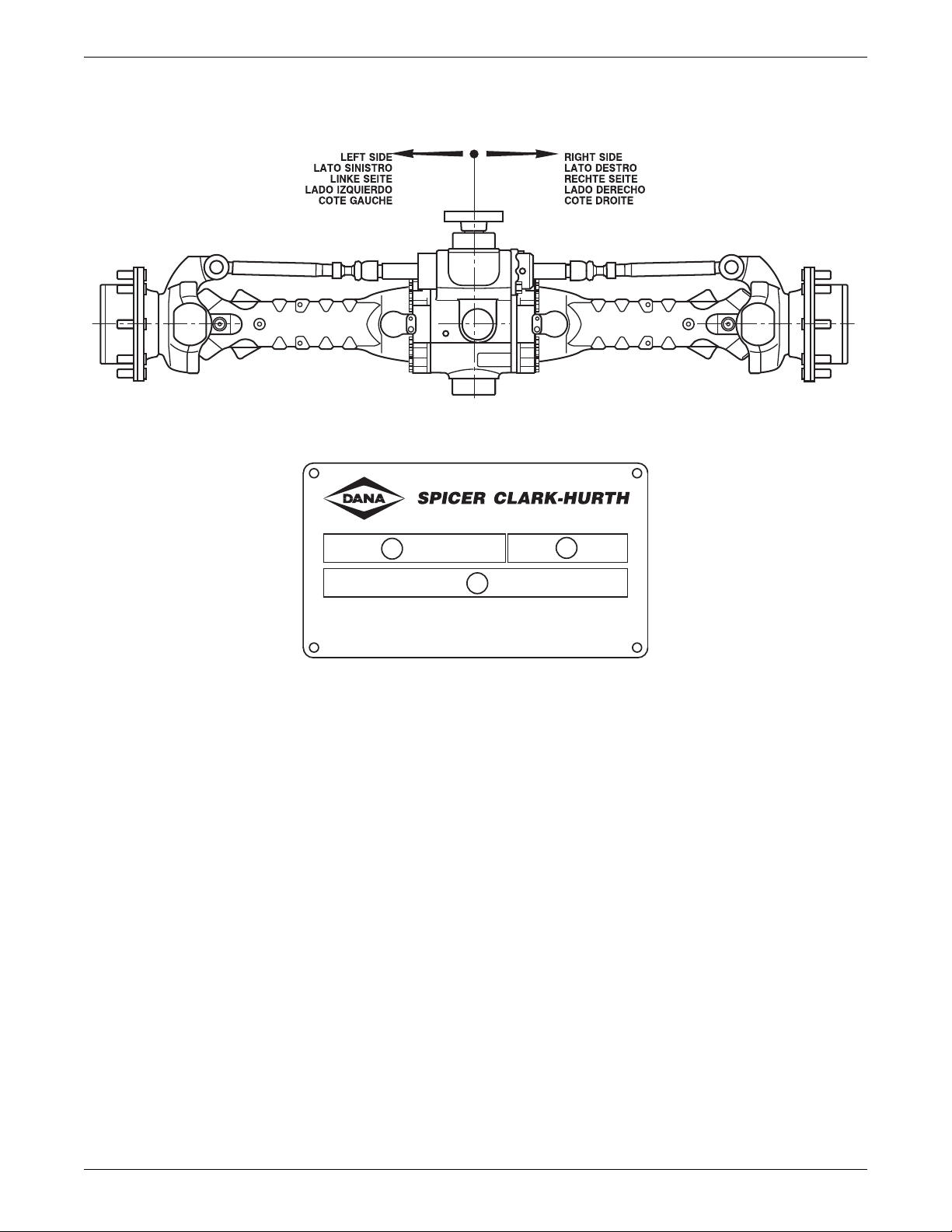
DEFINITION OF VIEWPOINTS
DATA PLATE
1 - Model number
2 - Serial number
3 - Lubricant
9Dana Holding CorporationASM-0025E - 212 Axle Service Manual

CONVERSION TABLES
CONVERSION TABLES
UNITS OF PRESSURE
1 ATM=1 BAR=105 PA=14.4 PSI
UNIT OF WEIGHT
N daN kN kg lbs
1N 1 0,1 0,001 0,102 0,225
1daN 10 1 0,01 1,02 2,25
1kN 1000 100 1 102 225
1kg 9,81 0,981 0,00981 1 2,205
UNITS OF TORQUE
N·m daN·m kN·m kg·m lb·in
1N·m 1 0,1 0,001 0,102 8,854
1daN·m 10 1 0,01 1,02 88,54
1kN·m 1000 100 1 102 8854
1kg·m 9,81 0,981 0,00981 1 86,8
1 lb·in 0,1129 0,01129 0,0001129 0,01152 1
10
Dana Holding Corporation ASM-0025E - 212 Axle Service Manual

TORQUE SPECIFICATIONS
TORQUE SPECIFICATIONS
COARSE PITCH
SIZE OF BOLT TYPE OF BOLT
8.8 8.8 + Loctite 270 10.9 10.9 + Loctite 270 12.9 12.9 + Loc tite 270
M6 x 1 mm 9,5 – 10,5 N·m 10,5 – 11,5 N·m 14,3 – 15,7 N·m 15,2 – 16,8 N·m 16,2 – 17,8 N·m 18,1 – 20 N·m
M8 x 1,25 mm 23,8 – 26,2 N·m 25,6 – 28,4 N·m 34,2 – 37,8 N·m 36,7 – 40,5 N·m 39 – 43 N·m 43,7 – 48,3 N·m
M10 x 1,5 mm 48 – 53 N·m 52 – 58 N·m 68 – 75 N·m 73 – 81 N·m 80 – 88 N·m 88 – 97 N·m
M12 x 1,75 mm 82 – 91 N·m 90 – 100 N·m 116 – 128 N·m 126 – 139 N·m 139 – 153 N·m 152 – 168 N·m
M14 x 2 mm 129 – 143 N·m 143 – 158 N·m 182 – 202 N·m 200 – 221 N·m 221 – 244 N·m 238 – 263 N·m
M16 x 2 mm 200 – 221 N·m 219 – 242 N·m 283 – 312 N·m 309 – 341 N·m 337 – 373 N·m 371 – 410 N·m
M18 x 2,5 mm 276 – 305 N·m 299 – 331 N·m 390 – 431 N·m 428 – 473 N·m 466 – 515 N·m 509 – 562 N·m
M20 x 2,5 mm 390 – 431 N·m 428 – 473 N·m 553 – 611 N·m 603 – 667 N·m 660 – 730 N·m 722 – 798 N·m
M22 x 2,5 mm 523 – 578 N·m 575 – 635 N·m 746 – 824 N·m 817 – 903 N·m 893 – 987 N·m 974 – 1076 N·m
M24 x 3 mm 675 – 746 N·m 732 – 809 N·m 950 – 1050 N·m 1040 – 1150 N·m 1140 – 1260 N·m 1240 – 1370 N·m
M27 x 3 mm 998 – 1103 N·m 1088 – 1202 N·m 1411 – 1559 N·m 1539 – 1701 N·m 1710 – 1890 N·m 1838 – 2032 N·m
M30 x 3,5 mm 1378 – 1523 N·m 1473 – 1628 N·m 1914 – 2115 N·m 2085 – 2305 N·m 2280 – 2520 N·m 2494 – 2757 N·m
FINE PITCH
SIZE OF BOLT TYPE OF BOLT
8.8 8.8 + Loctite 270 10.9 10.9 + Loctite 270 12.9 12.9 + Loc tite 270
M8 x 1 mm 25,7 – 28,3 N·m 27,5 – 30,5 N·m 36,2 – 39,8 N·m 40 – 44 N·m 42,8 – 47,2 N·m 47,5 – 52,5 N·m
M10 x 1,25 mm 49,4 – 54,6 N·m 55,2 – 61 N·m 71,5 – 78,5 N·m 78 – 86 N·m 86 – 94 N·m 93 – 103 N·m
M12 x 1,25 mm 90 – 100 N·m 98 – 109 N·m 128 – 142 N·m 139 – 154 N·m 152 – 168 N·m 166 – 184 N·m
M12 x 1,5 mm 86 – 95 N·m 94 – 104 N·m 120 – 132 N·m 133 – 147 N·m 143 – 158 N·m 159 – 175 N·m
M14 x 1,5 mm 143 – 158 N·m 157 – 173 N·m 200 – 222 N·m 219 – 242 N·m 238 – 263 N·m 261 – 289 N·m
M16 x 1,5 mm 214 – 236 N·m 233 – 257 N·m 302 – 334 N·m 333 – 368 N·m 361 – 399 N·m 394 – 436 N·m
M18 x 1,5 mm 312 – 345 N·m 342 – 378 N·m 442 – 489 N·m 485 – 536 N·m 527 – 583 N·m 580 – 641 N·m
M20 x 1,5 mm 437 – 483 N·m 475 – 525 N·m 613 – 677 N·m 674 – 745 N·m 736 – 814 N·m 808 – 893 N·m
M22 x 1,5 mm 581 – 642 N·m 637 – 704 N·m 822 – 908 N·m 903 – 998 N·m 998 – 1103 N·m 1078 – 1191 N·m
M24 x 2 mm 741 – 819 N·m 808 – 893 N·m 1045 – 1155 N·m 1140 – 1260 N·m 1235 – 1365 N·m 1363 – 1507 N·m
M27 x 2 mm 1083 – 1197 N·m 1178 – 1302 N·m 1520 – 1680 N·m 1672 – 1848 N·m 1834 – 2027 N·m 2000 – 2210 N·m
M30 x 2 mm 1511 – 1670 N·m 1648 – 1822 N·m 2138 – 2363 N·m 2332 – 2577 N·m 2565 – 2835 N·m 2788 – 3082 N·m
11Dana Holding CorporationASM-0025E - 212 Axle Service Manual
TORQUE SPECIFICATIONS
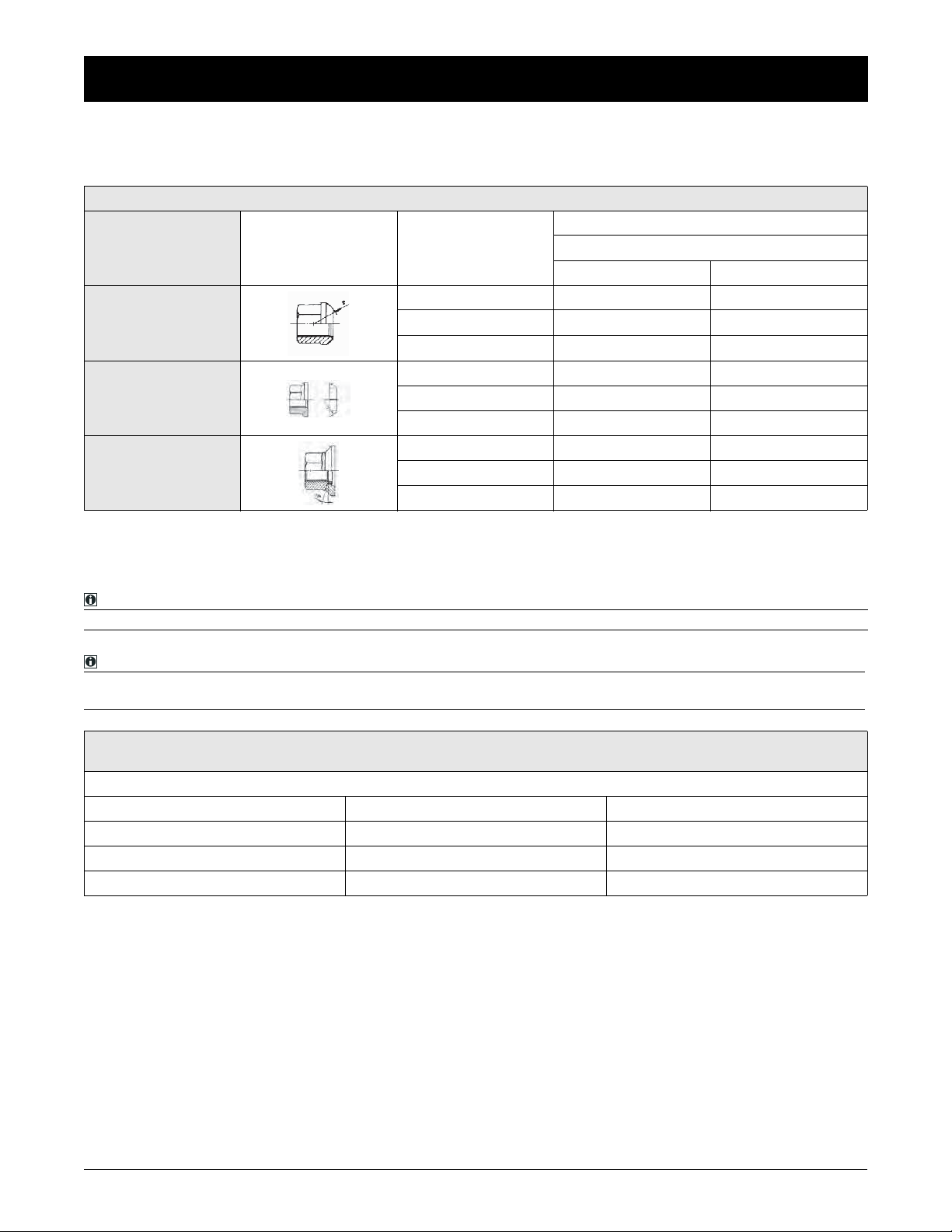
WHEEL NUT TIGHTENING TORQUES
Wheel nut tightening torques recommended from rim's O.E.M. with reference the the quality of the rim's material.
WHEEL NUT TIGHTENING TORQUES
RECOMMENDED WHEEL NUTS TORQUE
CHARACTERISTICS ILLUSTRATION WHEEL STUD THREAD
WHEEL NUTS WITH
INTEGRATED
SPHERICAL COLLAR
M18X1, 5 mm 330 N·m 460 N·m
M20X1, 5 mm 490 N·m 630 N·m
M22X1, 5 mm 630 N·m 740 N·m
RIM MATERIAL QUALITY
ST 37 **ST 52
FLAT COLLAR WHEEL
NUTS WITH SEPARATE
SPHERICAL LOCK
WASHER
WHEEL NUTS WITH
INTEGRATE SEAT
CAPTIVE WASHER
M18X1, 5 mm 270 N·m 360 N·m
M20X1, 5 mm 360 N·m 450 N·m
M22X1, 5 mm 460 N·m 550 N·m
M18X1, 5 mm 260 N·m 360 N·m
M20X1, 5 mm 350 N·m 500 N·m
M22X1, 5 mm 450 N·m 650 N·m
**RIM'S MATERIAL ST 52 IS RECOMMENDED BY DANA ON AXLE APPLICATION. IT IS THE OPTIMUM MATERIAL FOR TIGHTENING THE RIM TO THE HUB.
NOTE:
The wheel nut tightening torque is related only on nut thread and stud thread dry. (Without oil or any lubricant).
NOTE:
The wheel nut tightening torque takes into consideration not only the nut + stud characteristics, but also the quality of
the rim material.
THE DANA OFFICIAL TIGHTENING TORQUE TABLE, INCLUDED IN EACH SERVICE MANUAL, SHOWS THE TORQUE FIGURE RELATED TO THE BOLT CHARACTERISTIC ONLY .
DANA OFFICIAL TIGHTENING TORQUE TABLE
NUT MATERIAL QUALITY 8.8 & 10.9 STUD MATERIAL QUALITY 10.9 *ALLOW TIGHT TORQUE
M18 x 1,5 mm M18 x 1,5 N·m 442 - 489 N·m
M20 x 1,5 mm M20 x 1,5 N·m 613 - 677 N·m
M22 x 1,5 mm M22 x 1,5 N·m 822 - 908 N·m
*THE TORQUE FIGURE ON NUT AND STUD COUPLING MUST BE RELATED ON STUD MATERIAL QUALITY
(DANA AXLE ARE 10.9 ONLY).
12
Dana Holding Corporation ASM-0025E - 212 Axle Service Manual
MAINTENANCE
3
1
3
4
4
2
2
1
2
3
4
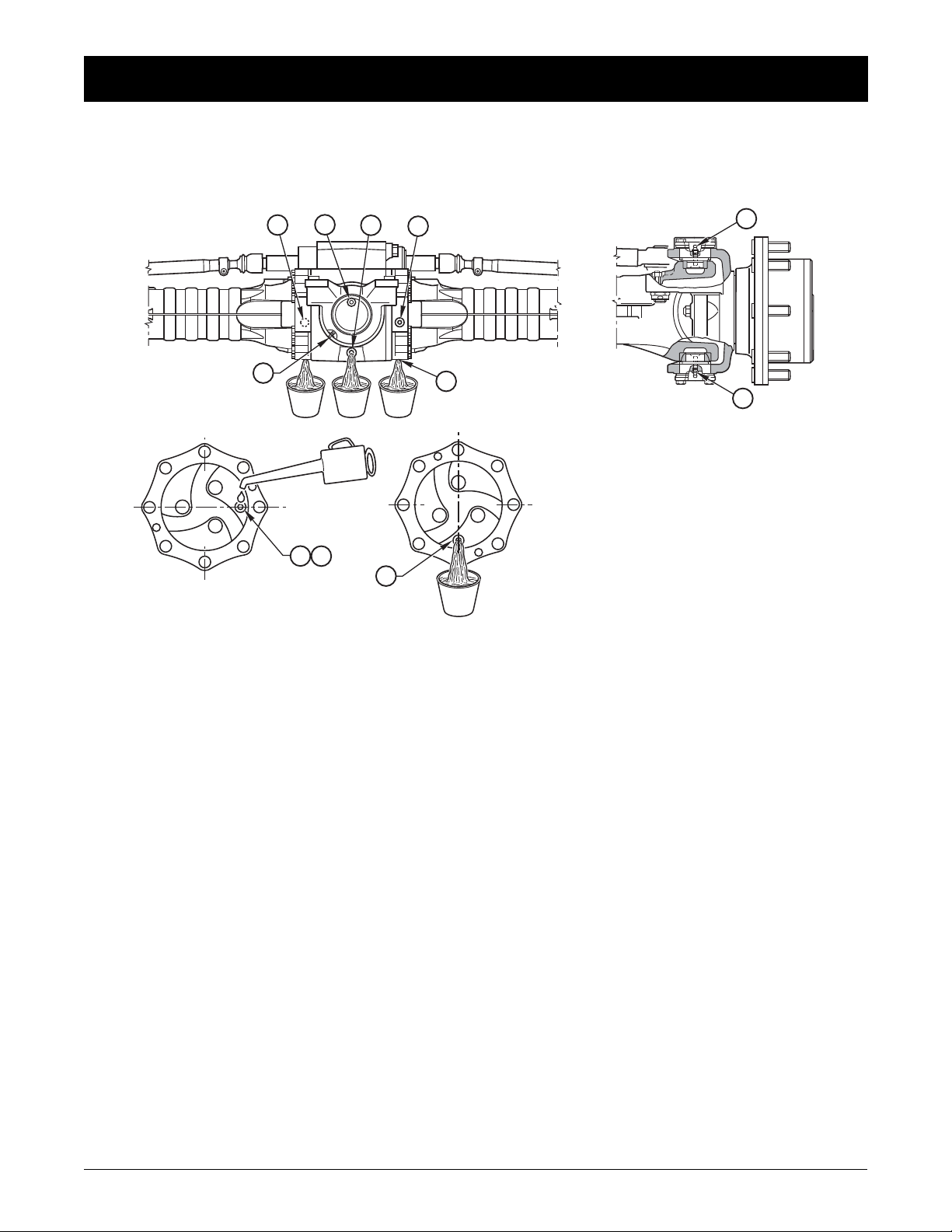
MAINTENANCE POINTS
MAINTENANCE
1 - Oil fill plug
2 - Oil drain plug
3 - Check level plug
13Dana Holding CorporationASM-0025E - 212 Axle Service Manual
MAINTENANCE
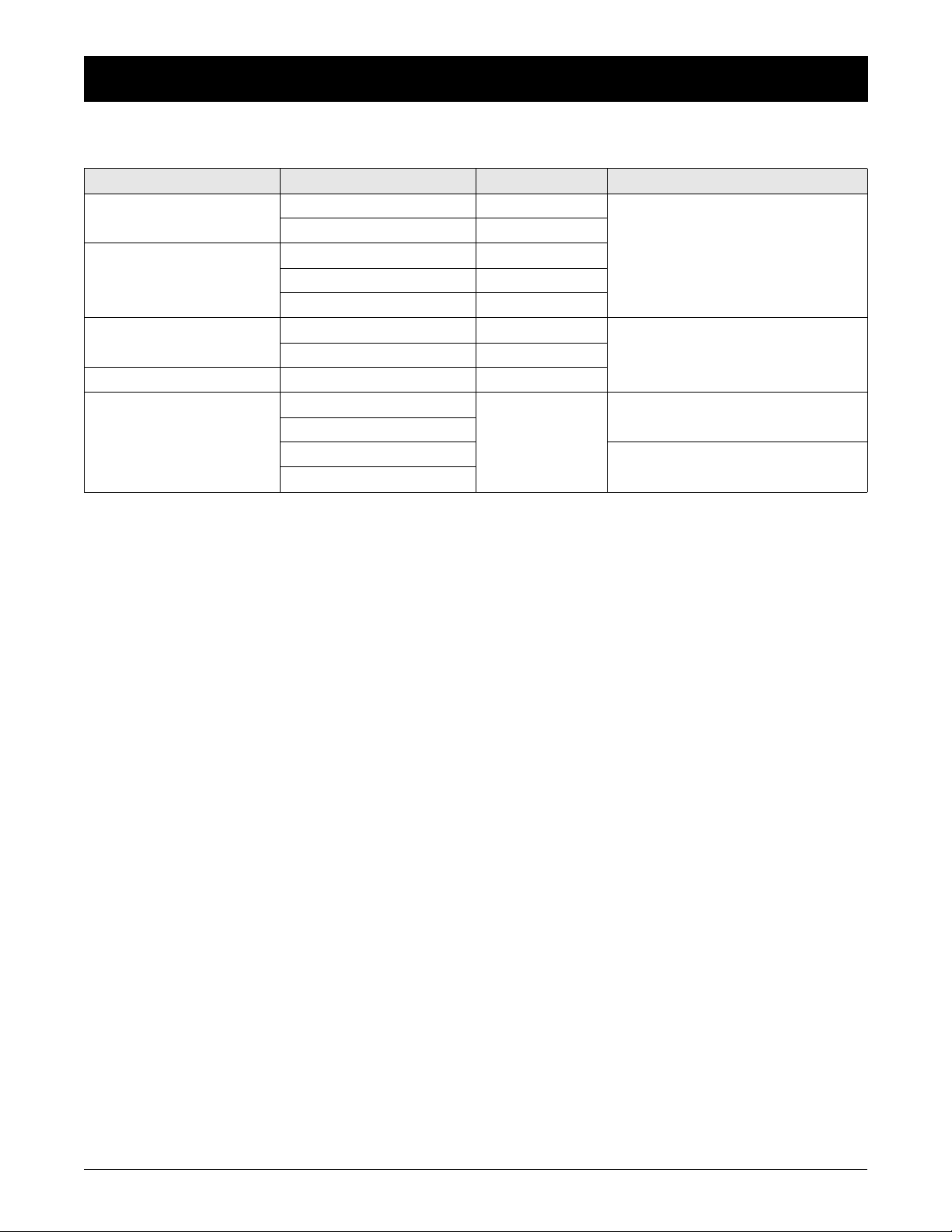
MAINTENANCE INTERVALS
OPERATION MEMBER FREQUENCY LUBRICANTS
Check levels
Oil change
Adjustment
Tightening Wheel nuts Every 200 hours **
Greasing
Differential Monthly
Planetary reduction Every 200 hours
Differential Every 800 hrs *
Planetary reduction Every 1000 hrs *
L.S. Differential Every 700 hrs */***
Negative brake Every 1000 hrs *
Service brake Every 500 hours
King Pin Tapered Bearings
Seals
King Pin Bushings
Trunnion Bushings
Normal work - Weekly
Severe duty - Daily
If working in severe duty conditions half intervals should be used
* Initially after 100 working hours
** Initially after 10 working hours
*** When it starts sounding noisy
**** According to DIN 51825 level KP2K-30 (NLGI #2) or KP3K-20 (NLGI #3); ASTM D4950 NLGI #2 GC-LB
SAE85W90 (API GL4 - MIL L-2105)
With additives for oil-bath brakes
SAE85W90 (API GL5 - MIL 2105-B)
With additives for oil-bath brakes, for units
presenting hypoid crown wheel and pinion
and/or self-locking differential gear
Only for mineral oil use e.g. ATF Dexron II.
Make sure that master cylinder seals are suitable for mineral oil.
NLGI 2 EP or NLGI 3 EP****
NLGI 2 EP or NLGI 3 EP****
w/Moly Additive
14
Dana Holding Corporation ASM-0025E - 212 Axle Service Manual

MAINTENANCE
LUBRICANT & SEALANT SPECIFICATIONS
1 - Locking, sealing and lubricating materials referred to in this manual are the same used in the shop-floor.
2 - The table below gives an account of the typical applications of each single material, in order to facilitate replacement with
similar products marketed by different brand names with different trade marks.
LOCTITE 242
Anaerobic product apt to prevent the loosening of screws, nuts and plugs. Used for medium-strength locking. Before using it,
completely remove any lubricant by using the specific activator.
LOCTITE 243
The oleocompatible alternative to 242. Does not require the activation of lubricated surfaces.
LOCTITE 270
Anaerobic product for very-high strength locking of screws and nuts. Before using it, completely remove any lubricant by using
the specific activator.
To remove parts, it may be necessary to heat them at 80° C approximately
LOCTITE 275
Anaerobic product suitable for high-strength locking and sealing of large threaded parts, bolts and stud bolts, for pipe sealing
and for protecting parts against tampering; suitable for sealing coupling surfaces with a maximum diametrical clearance of 0.25
mm.
LOCTITE 510
Anaerobic product for the hermetic sealing of flanged units and screw holes communicating with fluids. Can seal clearances
between flanges up to 0.2 mm.
LOCTITE 577
Quick anaerobic sealant for sealing threaded portions of conical or cylindrical unions up to M80. Before using it, remove any
lubricant with the specific activator. After polymerisation, disassembly may result rather difficult, so heating may be necessary
for larger diameters.
LOCTITE 638
Anaerobic adhesive for fast and high-strength gluing of cylindrical metal joints (hub on shaft). Can glue together parts with clearance ranging between 0.1 and 0.25 mm.
LOCTITE 648
Anaerobic adhesive for fast and medium-strength gluing of cylindrical metal joints (hub on shaft). Can glue together parts with
radial clearance below 0.1 mm.
AREXONS (REPOSITIONABLE JOINTING COMPOUND FOR SEALS)
Solvent-based sealing compound for elastic seals, drying through evaporation. Used for sealing the outer diameter of sealing
rings for rotating shafts with outer metal reinforcement.
SILICONE
Semi-fluid adhesive material used for sealing and filling and to protect components from environmental and physical elements.
Polymerises with non-corrosive dampness.
TECNO LUBE/101 (SILICONE-BASED GREASE)
Highly adhesive synthetic grease, with silicone compounds added.
Applied to adjustment screws with hole communicating with oil-type fluids.
Used when frequent adjusting is required.
MOLIKOTE (DOW CORNING)
Lubricating compound containing molybdenum disulphide, used to lubricate articulation pins and to prevent sticking and oxidation of parts that are not lubricated on a regular basis.
(LITHIUM-BASED) GREASE
Applied to bearings, sliding parts and used to lubricate seals or parts during assembly.
15Dana Holding CorporationASM-0025E - 212 Axle Service Manual

MAINTENANCE
16
Dana Holding Corporation ASM-0025E - 212 Axle Service Manual

SAFETY PRECAUTIONS
DANGER
WARNING
NOTICE
1 - During all operations described in this manual, the axle should be fastened onto a trestle, while the other parts
mentioned should rest on supporting benches.
2 - When removing one of the arms, an anti-tilting safety trestle should be placed under the other arm.
3 - When working on an arm that is fitted on the machine, make sure that the supporting trestles are correctly po-
sitioned and that the machine is locked lengthways.
4 - Do not admit any other person inside the work area; mark off the area, hang warning signs and remove the igni-
tion key from the machine.
5 - Use only clean, quality tools; discard all worn, damaged, lowquality or improvised wrenches and tools. Ensure
that all torque wrenches have been checked and calibrated.
6 - Always wear gloves and non-slip rubber shoes when performing repair work.
7 - Should you stain a surface with oil, remove marks straight away.
8 - Dispose of all lubricants, seals, rags and solvents once work has been completed. Treat them as special waste
and dispose of them according to the relative law provisions obtaining in the country where the axles are being
overhauled.
9 - Make sure that only weak solvents are used for cleaning purposes; avoid using turpentine, dilutants and toluol,
xylolbased or similar solvents; use light solvents such as Kerosene, mineral spirits or water-based, environment
friendly solvents.
10 - For the sake of clarity, the parts that do not normally need to be removed have not been reproduced in some
of the diagrams.
11 - For agricultural axles, the terms RIGHT and LEFT refer to the position from operator’s seat. For construcition
axle, the terms RIGHT and LEFT refer to the position outside facing the machine (with the input drive facing
forward).
12 - After repair work has been completed, accurately touch up any coated part that may have been damaged.
13 - Follow all safety instructions in the Original Equipment Manufacturer (OEM) manual that came with the vehicle.
CAUTION
Indicates an imminently hazardous situation which, if
not avoided, will result in death or serious injury.
Indicates an imminently hazardous situation which, if
not avoided, will result in death or serious injury.
Indicates a potentially hazardous situation which, if not
avoided, may result in moderate or minor injury.
Indicates a situation which, if not avoided, may result
in if not avoided, may result in damage to components.
17Dana Holding CorporationASM-0025E - 212 Axle Service Manual

MAINTENANCE
18
Dana Holding Corporation ASM-0025E - 212 Axle Service Manual
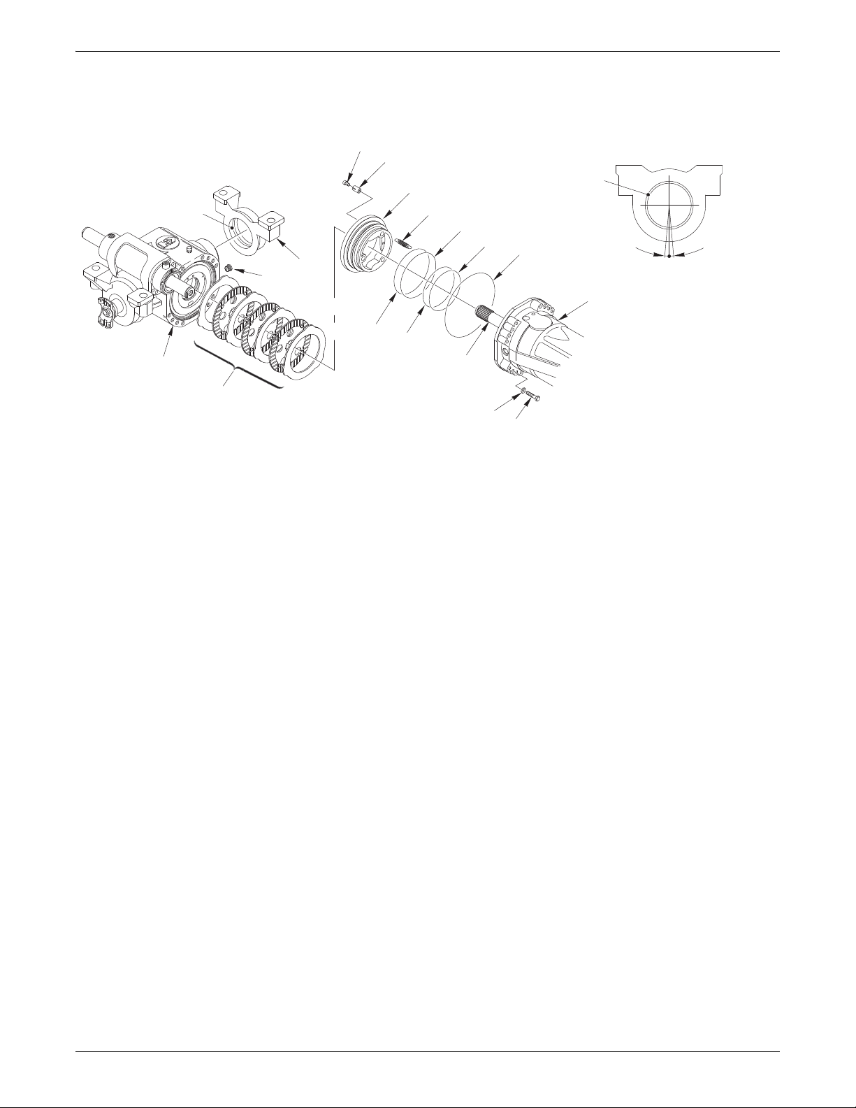
CHECKING WEAR AND REPLACING THE BRAKING DISCS
EXPLODED VIEW
10
15
9
12
8
11
14
16
18
5
4
17
2
1
13
6
7
17
MAXIMUM 10°
3
19Dana Holding CorporationASM-0025E - 212 Axle Service Manual
DISASSEMBLY
T1
S
T1
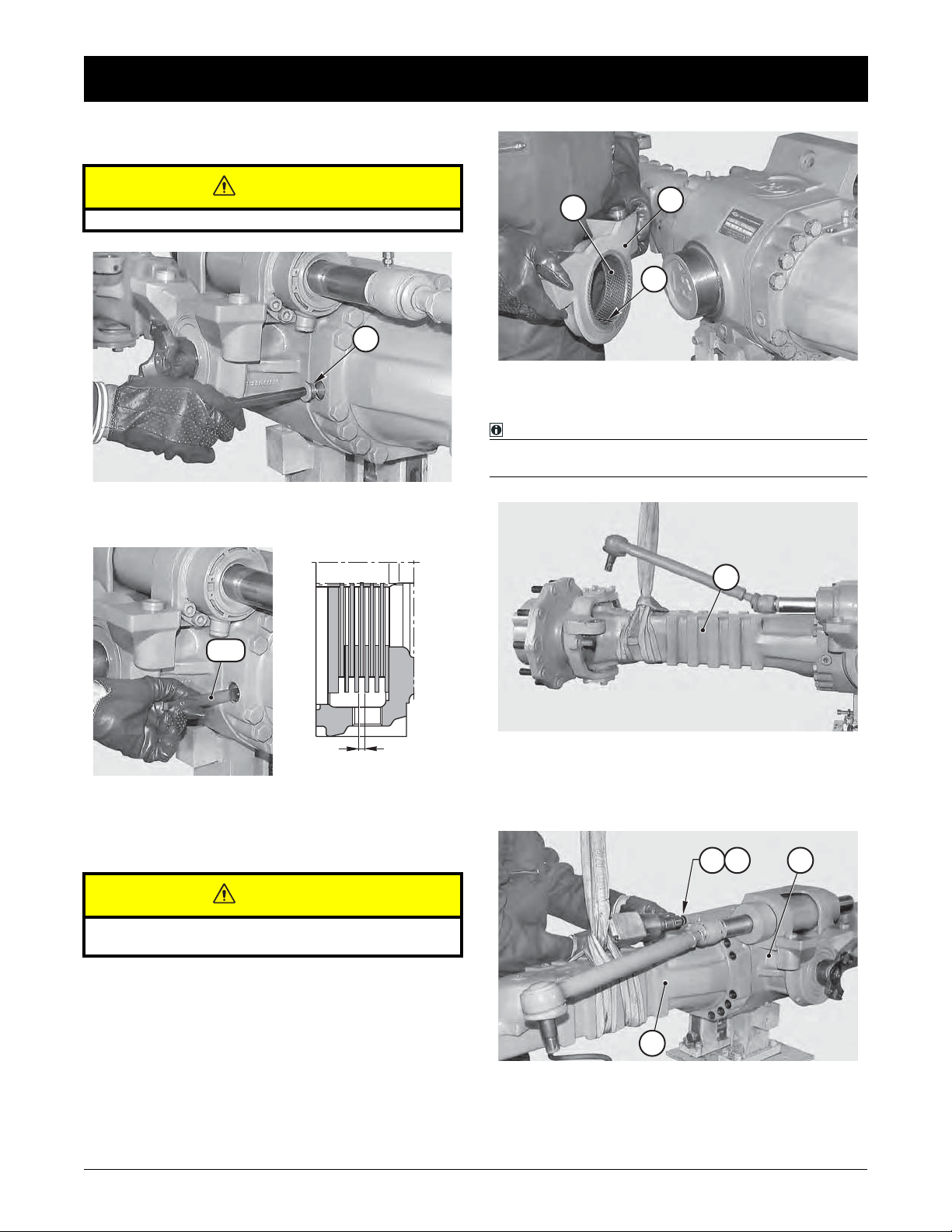
DISASSEMBLY
CAUTION
Perform all operations on both arms.
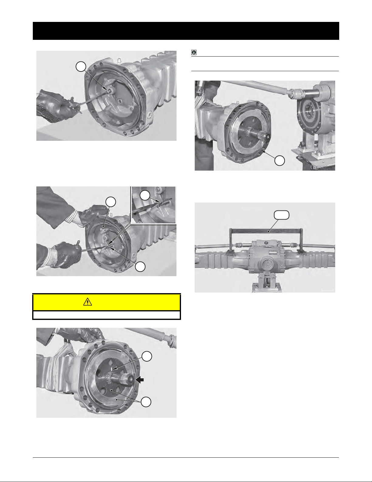
FIGURE 1:
Remove the oil-level plug (1).
A
2
A
17
1
FIGURE 3: Remove the swinging support (2) on the side opposite the drive.
NOTE:
If the bushing (17) is worn and needs replacing, write
down the assembly side of the connection notch "A".
3
FIGURE 4: Disconnect the pins of the steering bars from the
steering case (See STEERING CYLINDER p. 47).
FIGURE 2: Apply the brakes and, keeping them under pressure, check the linings "S" between the disks using tool T1
(See drawing T1 p. 24).
Minimum "S": 4.5 mm.
Sling the arm (3) to be removed and put the rod under slight
tension.
CAUTION
Replace the braking disks and the intermediate disks on
both sides if necessary.
3
FIGURE 5: Loosen and remove the screws (4) and the wa-
20
Dana Holding Corporation ASM-0025E - 212 Axle Service Manual
shers (5) that fix the arm (3) to the central body (6).
64 5
DISASSEMBLY
CAUTION
CAUTION
7
3
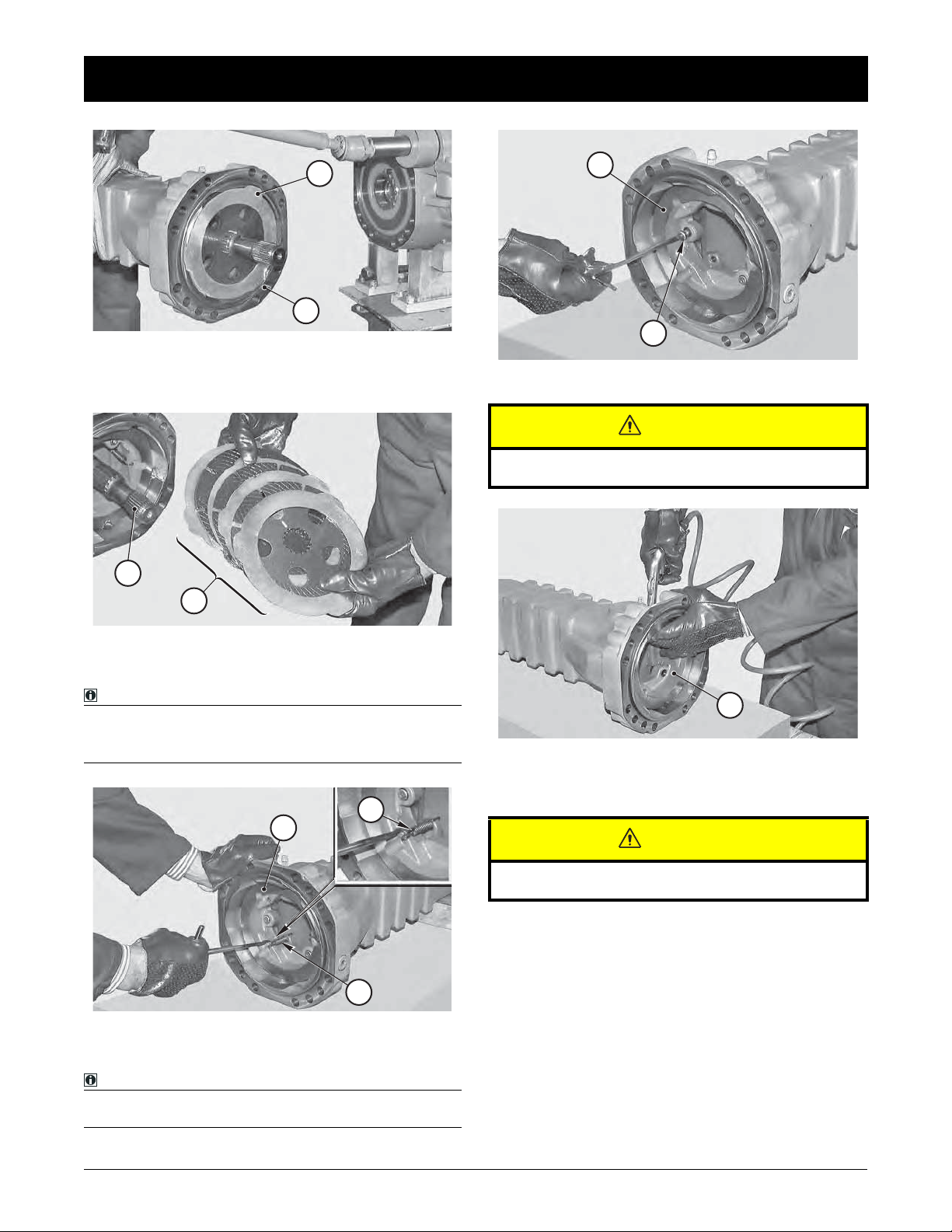
FIGURE 6: Remove the arm (3) together with the pack of the
braking disks (7).
Place the arm on a bench.
18
7
9
10
FIGURE 9: Remove the pin screws (10) guiding the piston (9).
If the screws are to be replaced, write down the different colors for the different brake gap.
FIGURE 7: Remove the braking disks (7) and write down their
order of assembly.
NOTE:
1 - If the disks do not need replacing, avoid switching
their position.
2 - Extract the u-joint (18).
8
9
8
FIGURE 8: Remove the reversal springs (8) from the piston
(9).
NOTE:
If the springs (8) are weak or deformed they must be replaced.
9
FIGURE 10: Slowly introduce compressed air through the
connection of the braking circuit in order to extract the entire
piston.
Hold on to the piston as it may be suddenly ejected and damaged.
21Dana Holding CorporationASM-0025E - 212 Axle Service Manual
ASSEMBLY
CAUTION
ASSEMBLY
14
12
11
13
3
9
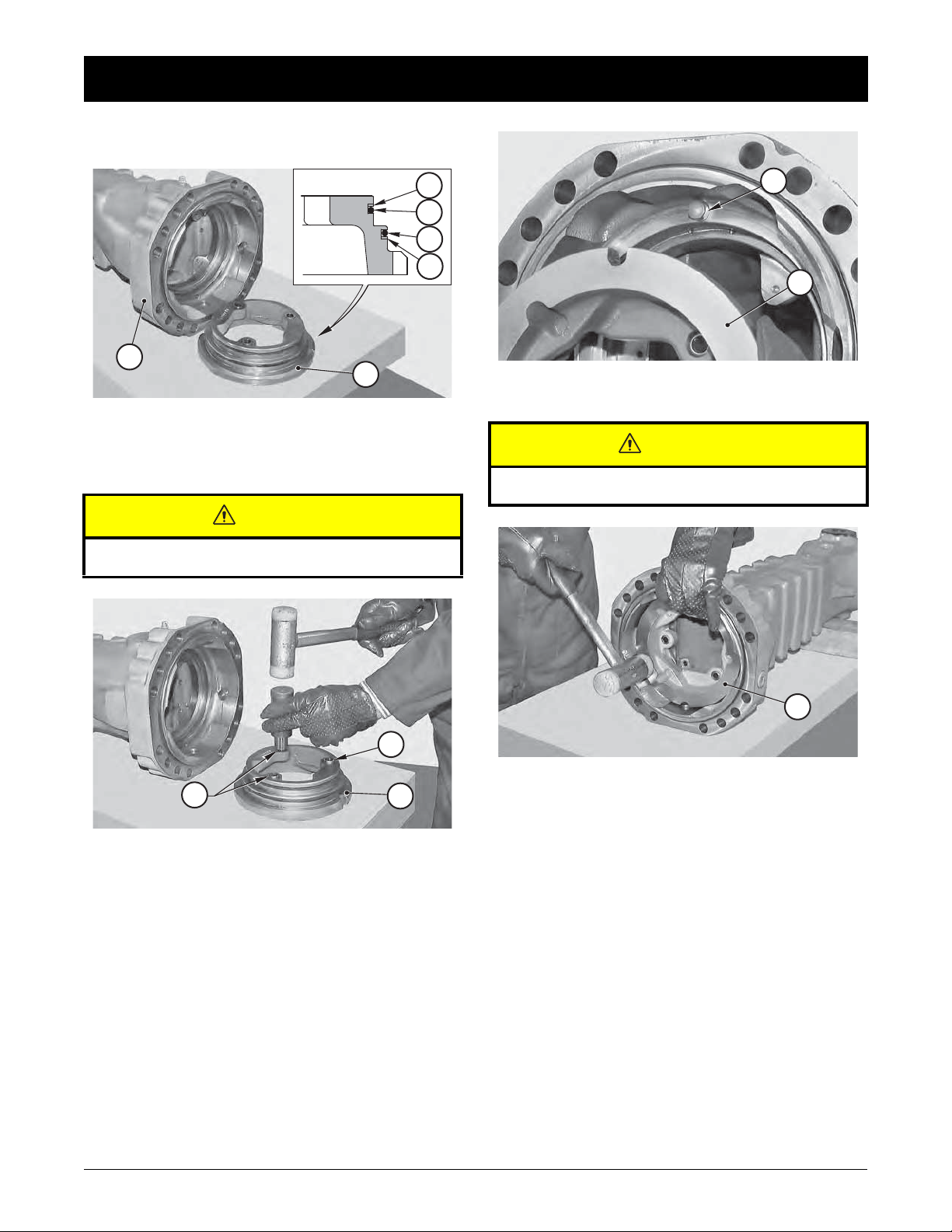
FIGURE 11: Accurately clean the piston (9) and the seats of
slide and seal.
Replace the o-rings (11) and (12) and the anti-extrusion rings
(13) and (14); make sure that the assembly side is correct.
CAUTION
A
A
9
FIGURE 13: Lubricate the seals (11) and (12) and fit the piston
(9) into the arm (3).
Make sure that the piston seat fits into the stop pin (A) inside
the arm.
Accurately check the positioning of the anti-extrusion rings
(13) and (14).
15
15
FIGURE 12: Insert the stroke automatic regulation springs
(15); place them in line with the piston (9).
9
9
FIGURE 14: Assist the insertion of the piston (9) by lightly
hammering around the edge with a plastic hammer.
22
Dana Holding Corporation ASM-0025E - 212 Axle Service Manual
10
FIGURE 15: Fit the pin screws (10) making sure that they are
all of the same color.
See Service Part List “Brake” section for bolt color detail.
Apply Loctite 270 to the thread.
Torque wrench setting: 5 - 7 N·m.
8
9
ASSEMBLY
NOTE:
When installing the steel discs, the slot corresponding to
the oil level cap should always be kept free.
16
FIGURE 18: Check that the positioning of the sealing ring (16)
on the arm is intact; install the complete arm.
Lock it into position using two screws (4) and washers (5).
8
FIGURE 16: Fit the reversal springs (8) on the piston (9).
CAUTION
Pay attention not to deform the connections of the springs.
B
B
T2
T2
FIGURE 19: Check the flatness of the arms using tool T2 (See
drawing T2 p. 24) and finally lock the arms with the screws (4)
and the washer (5) using the criss-cross method.
Torque wrench setting: 298 N·m
7
FIGURE 17:
in the arm following the correct sequence; orient them so that the
oil circulation holes and the marks "B" are perfectly lined up.
Slightly lubricate the braking disks (7) and fit them
23Dana Holding CorporationASM-0025E - 212 Axle Service Manual
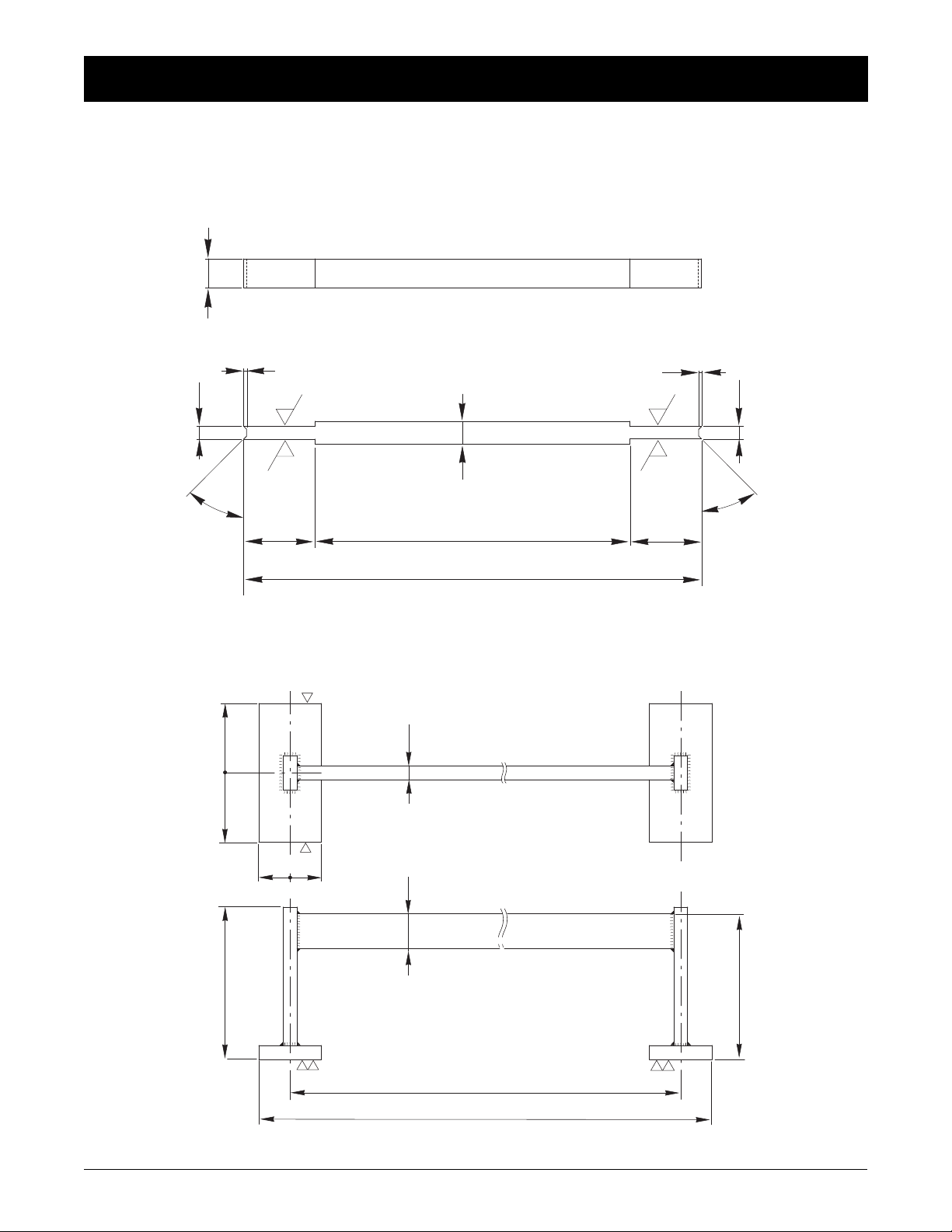
SPECIAL TOOLS
32
32
32
32
10
4.5
25
45 °
110
160
25
1
4.3
45 °
8
1
SPECIAL TOOLS
T1
P/N: 2313
T2
P/N: 2305
200
0.1
±
120
20
=
=
90
=
=
50
0.1
±
120
840
24
Dana Holding Corporation ASM-0025E - 212 Axle Service Manual
930
COMPLETE STEERING CASE
9
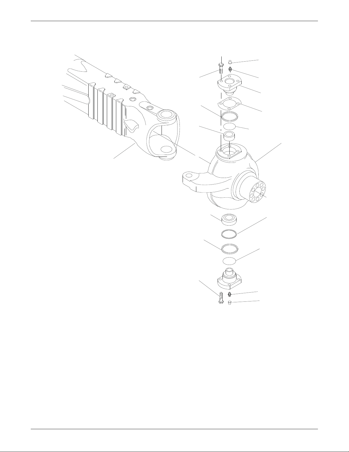
EXPLODED VIEW
6
18
9
10
10
8
5
4
3
2
1
12
13
14
15
16
17
25Dana Holding CorporationASM-0025E - 212 Axle Service Manual
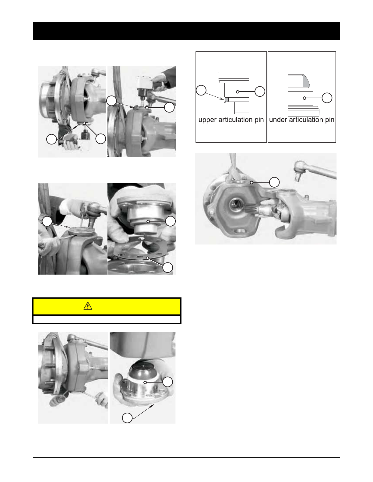
DISASSEMBLY
DISASSEMBLY
4
8
15
FIGURE 1: Loosen and remove the capscrews (15)(8) from
the articulation pin (19)(4).
4
19
9
3
4
1
FIGURE 4: Remove the complete steering case (1).
19
3
FIGURE 2: Using two levers, remove the top articulation pin
(4) complete with front seal (9) and shims (3).
CAUTION
Pay attention not to damage the surfaces.
10
19
FIGURE 3: Remove the bottom articulation (19) pin complete
with front sealing ring (10).
26
Dana Holding Corporation ASM-0025E - 212 Axle Service Manual
ASSEMBLY
140 N·m
10
140 N·m
ASSEMBLY
1
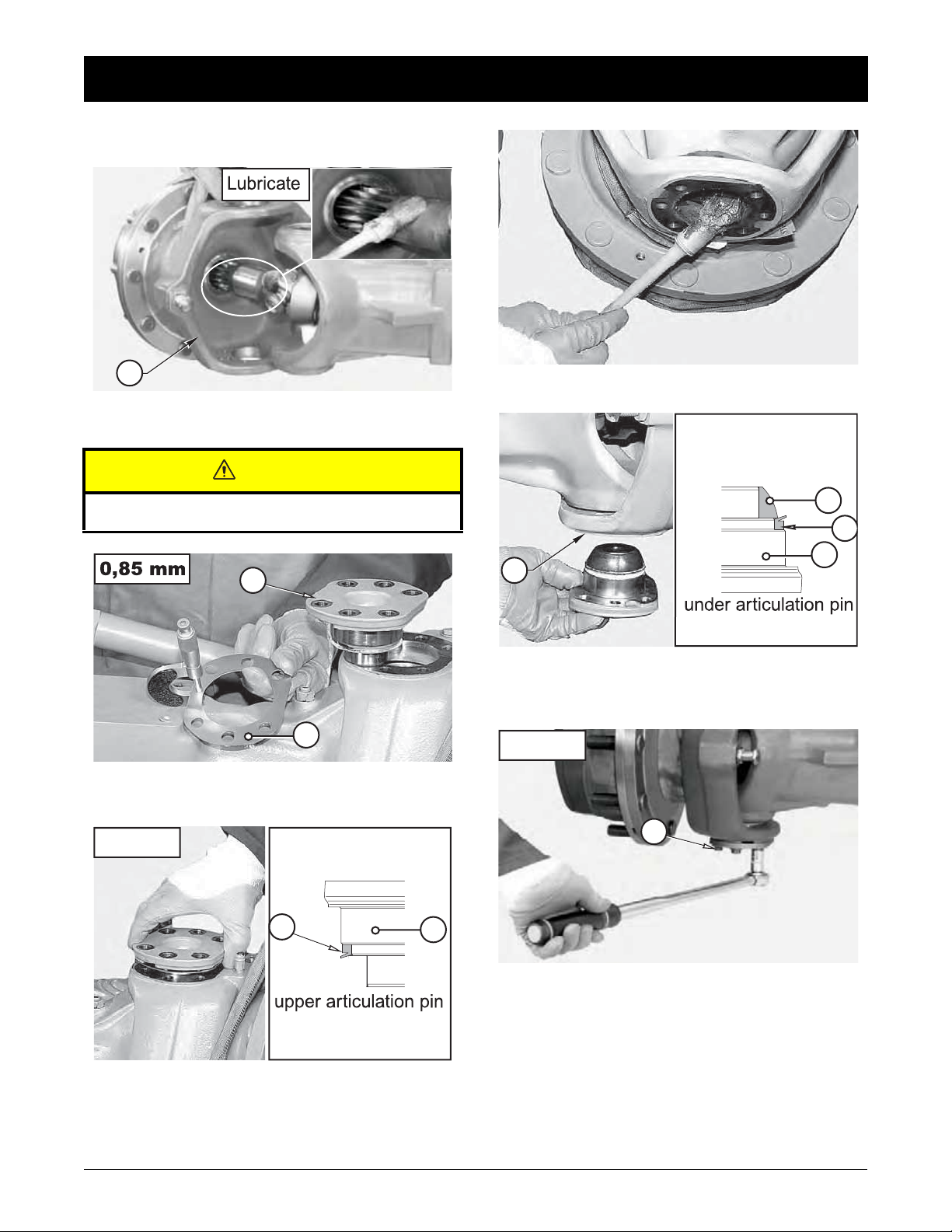
FIGURE 5: Lubricate the terminal of the u-joint and install the
steering case (1).
CAUTION
Pay due attention not to damage the dust cover rings and
the sealing rings.
4
3
FIGURE 6: Prepare a series of shims (3) of 0,85 mm. To be
assembled under the upper pin (4).
FIGURE 8: Lubricate steering case.
12
19
1
FIGURE 9: Fit the unit (19) in the steering case (1). Position
the screws (15) and tighten.
Check for the correct assembly side of the seal (10).
3
FIGURE 7:
bricate and install the unit in the steering case.
Position the screws (8) and tighten with torque wrench 140N·m.
Check the correct assembly side of the seal (3).
Fit a new seal (3) onto the top articulation pin (4). Lu-
4
15
FIGURE 10: Tighten the new capscrews (15) of top and bottom articulation pins in sequence using the criss-cross method.
Torque wrench setting: 140 N·m
27Dana Holding CorporationASM-0025E - 212 Axle Service Manual
ASSEMBLY
30 - 60 N·m
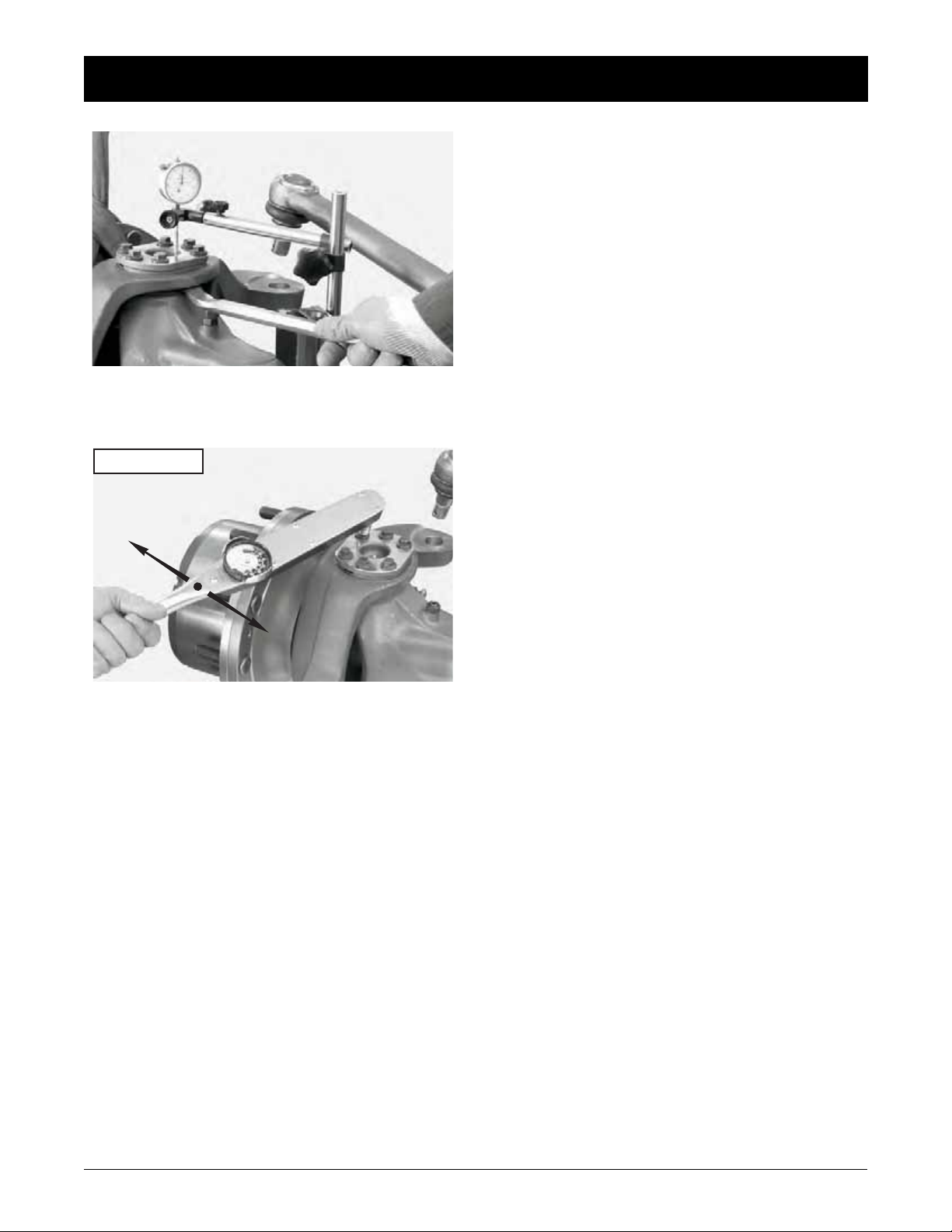
FIGURE 11: Check with a lever that there is no vertical gap.
In case there is any gap, determine the width and reduce it by
removing shims.
FIGURE 12: Check the torque of the pins, which has to be
between 30 and 60 N·m.
If the preliminary measured value is too high, the shims have
to be increased.
28
Dana Holding Corporation ASM-0025E - 212 Axle Service Manual
 Loading...