

Page 1
Service and Maintenance Manual
Models
T350
P/N - 3121198
January 9, 2013
Page 2

Page 3
INTRODUCTION
SECTION A. INTRODUCTION - MAINTENANCE SAFETY
PRECAUTIONS
AGENERAL
This section contains the general safety precautions
which must be observed during maintenance of the aerial
platform. It is of utmost importance that maintenance personnel pay strict attention to these warnings and precautions to avoid possible injury to themselves or others, or
damage to the equipment. A maintenance program must
be followed to ensure that the machine is safe to operate.
MODIFICATION OR ALTERATION OF AN AERIAL WORK PLATFORM SHALL BE MADE ONLY WITH WRITTEN PERMISSION
FROM THE MANUFACTURER.
The specific precautions to be observed during maintenance are inserted at the appropriate point in the manual.
These precautions are, for the most part, those that apply
when servicing hydraulic and larger machine component
parts.
Your safety, and that of others, is the first consideration
when engaging in the maintenance of equipment. Always
be conscious of weight. Never attempt to move heavy
parts without the aid of a mechanical device. Do not allow
heavy objects to rest in an unstable position. When raising
a portion of the equipment, ensure that adequate support
is provided.
CMAINTENANCE
FAILURE TO COMPLY WITH SAFETY PRECAUTIONS LISTED IN
THIS SECTION COULD RESULT IN MACHINE DAMAGE, PERSONNEL INJURY OR DEATH AND IS A SAFETY VIOLATION.
• ENSURE REPLACEMENT PARTS OR COMPONENTS
ARE IDENTICAL OR EQUIVALENT TO ORIGINAL PARTS
OR COMPONENTS.
• NO SMOKING IS MANDATORY. NEVER REFUEL DURING ELECTRICAL STORMS. ENSURE THAT FUEL CAP
IS CLOSED AND SECURE AT ALL OTHER TIMES.
• REMOVE ALL RINGS, WATCHES AND JEWELRY WHEN
PERFORMING ANY MAINTENANCE.
• DO NOT WEAR LONG HAIR UNRESTRAINED, OR
LOOSE-FITTING CLOTHING AND NECKTIES WHICH
ARE APT TO BECOME CAUGHT ON OR ENTANGLED
IN EQUIPMENT.
• OBSERVE AND OBEY ALL WARNINGS AND CAUTIONS
ON MACHINE AND IN SERVICEMANUAL.
• KEEP OIL, GREASE, WATER, ETC. WIPED FROM
STANDING SURFACES AND HAND HOLDS.
•USE CAUTION WHEN CHECKING A HOT, PRESSURIZED COOLANT SYSTEM.
SINCE THE MACHINE MANUFACTURER HAS NO DIRECT CONTROL OVER THE FIELD INSPECTION AND MAINTENANCE,
SAFETY IN THIS AREA RESPONSIBILITY OF THE OWNER/OPERATO R.
B HYDRAULIC SYSTEM SAFETY
It should be noted that the machines hydraulic systems
operate at extremely high potentially dangerous pressures. Every effort should be made to relieve any system
pressure prior to disconnecting or removing any portion of
the system.
• NEVER WORK UNDER AN ELEVATED BOOM UNTIL
BOOM HAS BEEN SAFELY RESTRAINED FROM ANY
MOVEMENT BY BLOCKING OR OVERHEAD SLING, OR
BOOM SAFETY PROP HAS BEEN ENGAGED.
• BEFORE MAKING ADJUSTMENTS, LUBRICATING OR
PERFORMING ANY OTHER MAINTENANCE, SHUT
OFF ALL POWER CONTROLS.
• BATTERY SHOULD ALWAYS BE DISCONNECTEDDURING REPLACEMENT OF ELECTRICAL COMPONENTS.
• KEEP ALL SUPPORT EQUIPMENT AND ATTACHMENTS STOWED IN THEIR PROPER PLACE.
• USE ONLY APPROVED, NONFLAMMABLE CLEANING
SOLVENTS.
3121198 – JLG Lift – A-1
Page 4

INTRODUCTION
REVISON LOG
Original Issue - January 15, 2005
Revised - July 15, 2005
Revised - August 26, 2005
Revised - December 12, 2005
Revised - February 24, 2006
Revised - May 1, 2007
Revised - September 28, 2011
Revised - January 9, 2013
A-2 – JLG Lift – 3121198
Page 5

TABLE OF CONTENTS
SECTION NO. TITLE PAGE NO.
SECTION A - INTRODUCTION - MAINTENANCE SAFETY PRECAUTIONS
A General . . . . . . . . . . . . . . . . . . . . . . . . . . . . . . . . . . . . . . . . . . . . . . . . . . . . . . . . . . . . . . . . . . . . . .A-1
B Hydraulic System Safety . . . . . . . . . . . . . . . . . . . . . . . . . . . . . . . . . . . . . . . . . . . . . . . . . . . . . . . . . A-1
C Maintenance . . . . . . . . . . . . . . . . . . . . . . . . . . . . . . . . . . . . . . . . . . . . . . . . . . . . . . . . . . . . . . . . . . A-1
SECTION 1 - SPECIFICATIONS
1.1 Operating specifications . . . . . . . . . . . . . . . . . . . . . . . . . . . . . . . . . . . . . . . . . . . . . . . . . . . . . . . . .1-1
1.2 Capacities . . . . . . . . . . . . . . . . . . . . . . . . . . . . . . . . . . . . . . . . . . . . . . . . . . . . . . . . . . . . . . . . . . . .1-1
1.3 Electric Power Unit . . . . . . . . . . . . . . . . . . . . . . . . . . . . . . . . . . . . . . . . . . . . . . . . . . . . . . . . . . . . .1-1
1.4 Tires . . . . . . . . . . . . . . . . . . . . . . . . . . . . . . . . . . . . . . . . . . . . . . . . . . . . . . . . . . . . . . . . . . . . . . . . . 1-1
1.5 Engine . . . . . . . . . . . . . . . . . . . . . . . . . . . . . . . . . . . . . . . . . . . . . . . . . . . . . . . . . . . . . . . . . . . . . . .1-2
Battery . . . . . . . . . . . . . . . . . . . . . . . . . . . . . . . . . . . . . . . . . . . . . . . . . . . . . . . . . . . . . . . . . . 1-2
1.6 Dimensional Data . . . . . . . . . . . . . . . . . . . . . . . . . . . . . . . . . . . . . . . . . . . . . . . . . . . . . . . . . . . . . .1-2
1.7 Lubrication. . . . . . . . . . . . . . . . . . . . . . . . . . . . . . . . . . . . . . . . . . . . . . . . . . . . . . . . . . . . . . . . . . . .1-2
Hydraulic Oil . . . . . . . . . . . . . . . . . . . . . . . . . . . . . . . . . . . . . . . . . . . . . . . . . . . . . . . . . . . . . 1-2
1.8 Major Component Weights . . . . . . . . . . . . . . . . . . . . . . . . . . . . . . . . . . . . . . . . . . . . . . . . . . . . . . .1-3
1.9 Pressure Settings . . . . . . . . . . . . . . . . . . . . . . . . . . . . . . . . . . . . . . . . . . . . . . . . . . . . . . . . . . . . . .1-3
1.10 Operator Maintenance & Lubrication . . . . . . . . . . . . . . . . . . . . . . . . . . . . . . . . . . . . . . . . . . . . . . .1-4
SECTION 2 - GENERAL
2.1 Machine Preparation, Inspection, and Maintenance . . . . . . . . . . . . . . . . . . . . . . . . . . . . . . . . . . .2-1
General. . . . . . . . . . . . . . . . . . . . . . . . . . . . . . . . . . . . . . . . . . . . . . . . . . . . . . . . . . . . . . . . . . 2-1
Preparation, Inspection, and Maintenance . . . . . . . . . . . . . . . . . . . . . . . . . . . . . . . . . . . . . . 2-1
Pre-Start Inspection . . . . . . . . . . . . . . . . . . . . . . . . . . . . . . . . . . . . . . . . . . . . . . . . . . . . . . . . 2-1
Pre-Delivery Inspection and Frequent Inspection . . . . . . . . . . . . . . . . . . . . . . . . . . . . . . . . . 2-1
Annual Machine Inspection . . . . . . . . . . . . . . . . . . . . . . . . . . . . . . . . . . . . . . . . . . . . . . . . . . 2-1
Preventative Maintenance . . . . . . . . . . . . . . . . . . . . . . . . . . . . . . . . . . . . . . . . . . . . . . . . . . . 2-1
2.2 Service and Guidelines . . . . . . . . . . . . . . . . . . . . . . . . . . . . . . . . . . . . . . . . . . . . . . . . . . . . . . . . . .2-2
General. . . . . . . . . . . . . . . . . . . . . . . . . . . . . . . . . . . . . . . . . . . . . . . . . . . . . . . . . . . . . . . . . . 2-2
Safety and Workmanship . . . . . . . . . . . . . . . . . . . . . . . . . . . . . . . . . . . . . . . . . . . . . . . . . . . 2-2
Cleanliness. . . . . . . . . . . . . . . . . . . . . . . . . . . . . . . . . . . . . . . . . . . . . . . . . . . . . . . . . . . . . . . 2-2
Components Removal and Installation . . . . . . . . . . . . . . . . . . . . . . . . . . . . . . . . . . . . . . . . . 2-2
Component Disassembly and Reassembly . . . . . . . . . . . . . . . . . . . . . . . . . . . . . . . . . . . . . 2-3
Pressure-Fit Parts. . . . . . . . . . . . . . . . . . . . . . . . . . . . . . . . . . . . . . . . . . . . . . . . . . . . . . . . . . 2-3
Bearings . . . . . . . . . . . . . . . . . . . . . . . . . . . . . . . . . . . . . . . . . . . . . . . . . . . . . . . . . . . . . . . . . 2-3
Gaskets . . . . . . . . . . . . . . . . . . . . . . . . . . . . . . . . . . . . . . . . . . . . . . . . . . . . . . . . . . . . . . . . . 2-3
Bolt Usage and Torque Application . . . . . . . . . . . . . . . . . . . . . . . . . . . . . . . . . . . . . . . . . . . 2-3
Hydraulic Lines and Electrical Wiring . . . . . . . . . . . . . . . . . . . . . . . . . . . . . . . . . . . . . . . . . . 2-3
Hydraulic System. . . . . . . . . . . . . . . . . . . . . . . . . . . . . . . . . . . . . . . . . . . . . . . . . . . . . . . . . . 2-3
Lubrication . . . . . . . . . . . . . . . . . . . . . . . . . . . . . . . . . . . . . . . . . . . . . . . . . . . . . . . . . . . . . . . 2-3
Battery . . . . . . . . . . . . . . . . . . . . . . . . . . . . . . . . . . . . . . . . . . . . . . . . . . . . . . . . . . . . . . . . . . 2-3
Lubrication and Servicing . . . . . . . . . . . . . . . . . . . . . . . . . . . . . . . . . . . . . . . . . . . . . . . . . . . 2-3
2.3 Lubrication and Information . . . . . . . . . . . . . . . . . . . . . . . . . . . . . . . . . . . . . . . . . . . . . . . . . . . . . .2-4
Hydraulic System. . . . . . . . . . . . . . . . . . . . . . . . . . . . . . . . . . . . . . . . . . . . . . . . . . . . . . . . . . 2-4
Hydraulic Oil . . . . . . . . . . . . . . . . . . . . . . . . . . . . . . . . . . . . . . . . . . . . . . . . . . . . . . . . . . . . . 2-4
Changing Hydraulic Oil . . . . . . . . . . . . . . . . . . . . . . . . . . . . . . . . . . . . . . . . . . . . . . . . . . . . . 2-4
Lubrication Specifications . . . . . . . . . . . . . . . . . . . . . . . . . . . . . . . . . . . . . . . . . . . . . . . . . . . 2-4
3121198 – JLG Lift – i
Page 6

TABLE OF CONTENTS
SECTION NO. TITLE PAGE NO.
2.4 Cylinder Drift Test . . . . . . . . . . . . . . . . . . . . . . . . . . . . . . . . . . . . . . . . . . . . . . . . . . . . . . . . . . . . . .2-5
Platform Drift . . . . . . . . . . . . . . . . . . . . . . . . . . . . . . . . . . . . . . . . . . . . . . . . . . . . . . . . . . . . . 2-5
Cylinder Drift . . . . . . . . . . . . . . . . . . . . . . . . . . . . . . . . . . . . . . . . . . . . . . . . . . . . . . . . . . . . . 2-5
2.5 Pins and Composite Bearing Repair Guidelines . . . . . . . . . . . . . . . . . . . . . . . . . . . . . . . . . . . . . .2-5
2.6 Welding on JLG Equipment . . . . . . . . . . . . . . . . . . . . . . . . . . . . . . . . . . . . . . . . . . . . . . . . . . . . . . 2-6
Do the Following When Welding on JLG Equipment . . . . . . . . . . . . . . . . . . . . . . . . . . . . . . 2-6
Do NOT Do the Following When Welding on JLG Equipment . . . . . . . . . . . . . . . . . . . . . . . 2-6
SECTION 3 - CHASSIS & TURNTABLE
3.1 Breaking-in a New Trailer . . . . . . . . . . . . . . . . . . . . . . . . . . . . . . . . . . . . . . . . . . . . . . . . . . . . . . . . 3-1
Retighten Lug Nuts at First 10, 25 & 50 Miles . . . . . . . . . . . . . . . . . . . . . . . . . . . . . . . . . . . . 3-1
Adjust Brake Shoes at First 200 Miles. . . . . . . . . . . . . . . . . . . . . . . . . . . . . . . . . . . . . . . . . . 3-1
Synchronizing the Brake Systems . . . . . . . . . . . . . . . . . . . . . . . . . . . . . . . . . . . . . . . . . . . . 3-1
3.2 Trailer inspection and Service Instructions. . . . . . . . . . . . . . . . . . . . . . . . . . . . . . . . . . . . . . . . . . .3-1
Fasteners and Frame Members . . . . . . . . . . . . . . . . . . . . . . . . . . . . . . . . . . . . . . . . . . . . . . 3-1
Brake Shoes and Drums . . . . . . . . . . . . . . . . . . . . . . . . . . . . . . . . . . . . . . . . . . . . . . . . . . . . 3-1
Manually Adjusting Brake Shoes. . . . . . . . . . . . . . . . . . . . . . . . . . . . . . . . . . . . . . . . . . . . . . 3-1
3.3 Electric Brakes. . . . . . . . . . . . . . . . . . . . . . . . . . . . . . . . . . . . . . . . . . . . . . . . . . . . . . . . . . . . . . . . . 3-2
Brake Controller. . . . . . . . . . . . . . . . . . . . . . . . . . . . . . . . . . . . . . . . . . . . . . . . . . . . . . . . . . . 3-2
Brake Cleaning and Inspection . . . . . . . . . . . . . . . . . . . . . . . . . . . . . . . . . . . . . . . . . . . . . . . 3-2
Shoes and Linings . . . . . . . . . . . . . . . . . . . . . . . . . . . . . . . . . . . . . . . . . . . . . . . . . . . . . . . . . 3-2
3.4 Hydraulic (Surge) Brakes . . . . . . . . . . . . . . . . . . . . . . . . . . . . . . . . . . . . . . . . . . . . . . . . . . . . . . . .3-2
Self Adjusting Mechanism . . . . . . . . . . . . . . . . . . . . . . . . . . . . . . . . . . . . . . . . . . . . . . . . . . . 3-3
Parking Brake . . . . . . . . . . . . . . . . . . . . . . . . . . . . . . . . . . . . . . . . . . . . . . . . . . . . . . . . . . . . 3-3
General Maintenance . . . . . . . . . . . . . . . . . . . . . . . . . . . . . . . . . . . . . . . . . . . . . . . . . . . . . . 3-3
3.5 Hubs, Drums, Wheel Bearings . . . . . . . . . . . . . . . . . . . . . . . . . . . . . . . . . . . . . . . . . . . . . . . . . . . .3-4
Hub Removal . . . . . . . . . . . . . . . . . . . . . . . . . . . . . . . . . . . . . . . . . . . . . . . . . . . . . . . . . . . . . 3-4
Brake Drum Inspection . . . . . . . . . . . . . . . . . . . . . . . . . . . . . . . . . . . . . . . . . . . . . . . . . . . . . 3-4
Bearing Inspection. . . . . . . . . . . . . . . . . . . . . . . . . . . . . . . . . . . . . . . . . . . . . . . . . . . . . . . . . 3-4
Bearing Lubrication . . . . . . . . . . . . . . . . . . . . . . . . . . . . . . . . . . . . . . . . . . . . . . . . . . . . . . . . 3-5
Seal Inspection and Replacement . . . . . . . . . . . . . . . . . . . . . . . . . . . . . . . . . . . . . . . . . . . . 3-5
Bearing Adjustment . . . . . . . . . . . . . . . . . . . . . . . . . . . . . . . . . . . . . . . . . . . . . . . . . . . . . . . . 3-5
3.6 Tires & Wheels. . . . . . . . . . . . . . . . . . . . . . . . . . . . . . . . . . . . . . . . . . . . . . . . . . . . . . . . . . . . . . . . . 3-7
Tire Inflation . . . . . . . . . . . . . . . . . . . . . . . . . . . . . . . . . . . . . . . . . . . . . . . . . . . . . . . . . . . . . . 3-7
Tire Wear . . . . . . . . . . . . . . . . . . . . . . . . . . . . . . . . . . . . . . . . . . . . . . . . . . . . . . . . . . . . . . . . 3-7
Tire Replacement. . . . . . . . . . . . . . . . . . . . . . . . . . . . . . . . . . . . . . . . . . . . . . . . . . . . . . . . . . 3-7
Wheel and Tire Replacement . . . . . . . . . . . . . . . . . . . . . . . . . . . . . . . . . . . . . . . . . . . . . . . . 3-7
Wheel Installation. . . . . . . . . . . . . . . . . . . . . . . . . . . . . . . . . . . . . . . . . . . . . . . . . . . . . . . . . . 3-8
Lug Nuts (Bolts) . . . . . . . . . . . . . . . . . . . . . . . . . . . . . . . . . . . . . . . . . . . . . . . . . . . . . . . . . . . 3-8
3.7 Hydraulic Brake Coupler. . . . . . . . . . . . . . . . . . . . . . . . . . . . . . . . . . . . . . . . . . . . . . . . . . . . . . . . .3-10
Troubleshooting. . . . . . . . . . . . . . . . . . . . . . . . . . . . . . . . . . . . . . . . . . . . . . . . . . . . . . . . . . . 3-10
Bleeding the Brake System . . . . . . . . . . . . . . . . . . . . . . . . . . . . . . . . . . . . . . . . . . . . . . . . . . 3-11
Towing . . . . . . . . . . . . . . . . . . . . . . . . . . . . . . . . . . . . . . . . . . . . . . . . . . . . . . . . . . . . . . . . . . 3-11
Backing Up . . . . . . . . . . . . . . . . . . . . . . . . . . . . . . . . . . . . . . . . . . . . . . . . . . . . . . . . . . . . . . 3-12
Maintenance . . . . . . . . . . . . . . . . . . . . . . . . . . . . . . . . . . . . . . . . . . . . . . . . . . . . . . . . . . . . . 3-13
Extended Storage Instructions . . . . . . . . . . . . . . . . . . . . . . . . . . . . . . . . . . . . . . . . . . . . . . . 3-13
Proper Towing Checklist . . . . . . . . . . . . . . . . . . . . . . . . . . . . . . . . . . . . . . . . . . . . . . . . . . . . 3-13
ii – JLG Lift – 3121198
Page 7

TABLE OF CONTENTS
SECTION NO. TITLE PAGE NO.
3.8 Combination Coupler . . . . . . . . . . . . . . . . . . . . . . . . . . . . . . . . . . . . . . . . . . . . . . . . . . . . . . . . . . . 3-14
Bleeding the Brake System . . . . . . . . . . . . . . . . . . . . . . . . . . . . . . . . . . . . . . . . . . . . . . . . . . 3-14
General Maintenance. . . . . . . . . . . . . . . . . . . . . . . . . . . . . . . . . . . . . . . . . . . . . . . . . . . . . . . 3-14
Servicing the Emergency Lever. . . . . . . . . . . . . . . . . . . . . . . . . . . . . . . . . . . . . . . . . . . . . . . 3-14
3.9 Hitch Coupler & Axle (CE Only) . . . . . . . . . . . . . . . . . . . . . . . . . . . . . . . . . . . . . . . . . . . . . . . . . . . 3-17
Ball Coupler . . . . . . . . . . . . . . . . . . . . . . . . . . . . . . . . . . . . . . . . . . . . . . . . . . . . . . . . . . . . . . 3-17
Coupling Head Maintenance. . . . . . . . . . . . . . . . . . . . . . . . . . . . . . . . . . . . . . . . . . . . . . . . . 3-19
Damper Maintenance . . . . . . . . . . . . . . . . . . . . . . . . . . . . . . . . . . . . . . . . . . . . . . . . . . . . . . 3-20
Brake Maintenance . . . . . . . . . . . . . . . . . . . . . . . . . . . . . . . . . . . . . . . . . . . . . . . . . . . . . . . . 3-21
Adjustment and Readjustment of the Overrun Braking System . . . . . . . . . . . . . . . . . . . . . . 3-24
Troubleshooting . . . . . . . . . . . . . . . . . . . . . . . . . . . . . . . . . . . . . . . . . . . . . . . . . . . . . . . . . . 3-26
3.10 Coupler Assembly (S/N 0030002099 to Present) . . . . . . . . . . . . . . . . . . . . . . . . . . . . . . . . . . . . . .3-27
Engaging Manual Lockout Lever. . . . . . . . . . . . . . . . . . . . . . . . . . . . . . . . . . . . . . . . . . . . . . 3-27
Servicing the Breakaway Assembly . . . . . . . . . . . . . . . . . . . . . . . . . . . . . . . . . . . . . . . . . . . 3-27
Actuator Maintenance . . . . . . . . . . . . . . . . . . . . . . . . . . . . . . . . . . . . . . . . . . . . . . . . . . . . . . 3-29
Coupler Maintenance . . . . . . . . . . . . . . . . . . . . . . . . . . . . . . . . . . . . . . . . . . . . . . . . . . . . . . 3-29
3.11 Trailer Jack (Solid wheels) . . . . . . . . . . . . . . . . . . . . . . . . . . . . . . . . . . . . . . . . . . . . . . . . . . . . . . .3-30
Installation . . . . . . . . . . . . . . . . . . . . . . . . . . . . . . . . . . . . . . . . . . . . . . . . . . . . . . . . . . . . . . . 3-30
Operation . . . . . . . . . . . . . . . . . . . . . . . . . . . . . . . . . . . . . . . . . . . . . . . . . . . . . . . . . . . . . . . . 3-30
Maintenance . . . . . . . . . . . . . . . . . . . . . . . . . . . . . . . . . . . . . . . . . . . . . . . . . . . . . . . . . . . . . 3-30
Assembly . . . . . . . . . . . . . . . . . . . . . . . . . . . . . . . . . . . . . . . . . . . . . . . . . . . . . . . . . . . . . . . . 3-31
3.12 Swing Motor (Prior to S/N 0030000960) . . . . . . . . . . . . . . . . . . . . . . . . . . . . . . . . . . . . . . . . . . . . . 3-31
Removal . . . . . . . . . . . . . . . . . . . . . . . . . . . . . . . . . . . . . . . . . . . . . . . . . . . . . . . . . . . . . . . . . 3-31
Disassembly. . . . . . . . . . . . . . . . . . . . . . . . . . . . . . . . . . . . . . . . . . . . . . . . . . . . . . . . . . . . . . 3-31
Assembly . . . . . . . . . . . . . . . . . . . . . . . . . . . . . . . . . . . . . . . . . . . . . . . . . . . . . . . . . . . . . . . . 3-32
Shaft Timing Procedure . . . . . . . . . . . . . . . . . . . . . . . . . . . . . . . . . . . . . . . . . . . . . . . . . . . . . 3-33
Installation . . . . . . . . . . . . . . . . . . . . . . . . . . . . . . . . . . . . . . . . . . . . . . . . . . . . . . . . . . . . . . . 3-34
3.13 Swing Motor (S/N 0030001050 to Present) . . . . . . . . . . . . . . . . . . . . . . . . . . . . . . . . . . . . . . . . . .3-36
Removal . . . . . . . . . . . . . . . . . . . . . . . . . . . . . . . . . . . . . . . . . . . . . . . . . . . . . . . . . . . . . . . . . 3-36
Disassembly and inspection . . . . . . . . . . . . . . . . . . . . . . . . . . . . . . . . . . . . . . . . . . . . . . . . . 3-36
Assembly . . . . . . . . . . . . . . . . . . . . . . . . . . . . . . . . . . . . . . . . . . . . . . . . . . . . . . . . . . . . . . . . 3-43
One Piece Stator Construction . . . . . . . . . . . . . . . . . . . . . . . . . . . . . . . . . . . . . . . . . . . . . . . 3-49
Installation . . . . . . . . . . . . . . . . . . . . . . . . . . . . . . . . . . . . . . . . . . . . . . . . . . . . . . . . . . . . . . . 3-50
3.14 Swing Bearing . . . . . . . . . . . . . . . . . . . . . . . . . . . . . . . . . . . . . . . . . . . . . . . . . . . . . . . . . . . . . . . . .3-51
Turntable Bearing Mounting Bolt Condition Check . . . . . . . . . . . . . . . . . . . . . . . . . . . . . . . 3-51
Wear Tolerance . . . . . . . . . . . . . . . . . . . . . . . . . . . . . . . . . . . . . . . . . . . . . . . . . . . . . . . . . . . 3-53
Swing Bearing Removal . . . . . . . . . . . . . . . . . . . . . . . . . . . . . . . . . . . . . . . . . . . . . . . . . . . . 3-53
Swing Bearing Installation . . . . . . . . . . . . . . . . . . . . . . . . . . . . . . . . . . . . . . . . . . . . . . . . . . . 3-54
Swing Bearing Torque Values . . . . . . . . . . . . . . . . . . . . . . . . . . . . . . . . . . . . . . . . . . . . . . . . 3-55
Swing Drive Checks. . . . . . . . . . . . . . . . . . . . . . . . . . . . . . . . . . . . . . . . . . . . . . . . . . . . . . . . 3-55
3121198 – JLG Lift – iii
Page 8

TABLE OF CONTENTS
SECTION NO. TITLE PAGE NO.
3.15 Engine . . . . . . . . . . . . . . . . . . . . . . . . . . . . . . . . . . . . . . . . . . . . . . . . . . . . . . . . . . . . . . . . . . . . . . .3-57
Throttle & Choke Adjustment . . . . . . . . . . . . . . . . . . . . . . . . . . . . . . . . . . . . . . . . . . . . . . . . 3-57
Fuel Valve Lever. . . . . . . . . . . . . . . . . . . . . . . . . . . . . . . . . . . . . . . . . . . . . . . . . . . . . . . . . . . 3-57
Checking RPM Level . . . . . . . . . . . . . . . . . . . . . . . . . . . . . . . . . . . . . . . . . . . . . . . . . . . . . . . 3-57
Choke Actuator . . . . . . . . . . . . . . . . . . . . . . . . . . . . . . . . . . . . . . . . . . . . . . . . . . . . . . . . . . . 3-58
Checking Oil Level. . . . . . . . . . . . . . . . . . . . . . . . . . . . . . . . . . . . . . . . . . . . . . . . . . . . . . . . . 3-58
3.16 Outrigger cylinder and Stabilizer . . . . . . . . . . . . . . . . . . . . . . . . . . . . . . . . . . . . . . . . . . . . . . . . . .3-60
Removal . . . . . . . . . . . . . . . . . . . . . . . . . . . . . . . . . . . . . . . . . . . . . . . . . . . . . . . . . . . . . . . . . 3-60
Installation . . . . . . . . . . . . . . . . . . . . . . . . . . . . . . . . . . . . . . . . . . . . . . . . . . . . . . . . . . . . . . . 3-61
3.17 Outrigger Limit Switches . . . . . . . . . . . . . . . . . . . . . . . . . . . . . . . . . . . . . . . . . . . . . . . . . . . . . . . . . 3-63
Adjustment. . . . . . . . . . . . . . . . . . . . . . . . . . . . . . . . . . . . . . . . . . . . . . . . . . . . . . . . . . . . . . . 3-63
3.18 Procedure For Retracting Outriggers Using Service Harness (Optional) . . . . . . . . . . . . . . . . . . .3-63
3.19 Leveling, Tilt Sensor Calibration . . . . . . . . . . . . . . . . . . . . . . . . . . . . . . . . . . . . . . . . . . . . . . . . . . .3-64
When Machine Is on a Firm Level Surface . . . . . . . . . . . . . . . . . . . . . . . . . . . . . . . . . . . . . . 3-64
Setup When Machine Is Not on Firm Level Surface and Adjustment Procedure: . . . . . . . . 3-65
3.20 Drive & Set. . . . . . . . . . . . . . . . . . . . . . . . . . . . . . . . . . . . . . . . . . . . . . . . . . . . . . . . . . . . . . . . . . . .3-67
Drive & Set Interlocks . . . . . . . . . . . . . . . . . . . . . . . . . . . . . . . . . . . . . . . . . . . . . . . . . . . . . . 3-68
3.21 Drive Motor . . . . . . . . . . . . . . . . . . . . . . . . . . . . . . . . . . . . . . . . . . . . . . . . . . . . . . . . . . . . . . . . . . . 3-72
Disassembly and inspection . . . . . . . . . . . . . . . . . . . . . . . . . . . . . . . . . . . . . . . . . . . . . . . . . 3-72
Assembly . . . . . . . . . . . . . . . . . . . . . . . . . . . . . . . . . . . . . . . . . . . . . . . . . . . . . . . . . . . . . . . . 3-79
One Piece Stator Construction . . . . . . . . . . . . . . . . . . . . . . . . . . . . . . . . . . . . . . . . . . . . . . . 3-85
3.22 Batteries (Electric Machines) . . . . . . . . . . . . . . . . . . . . . . . . . . . . . . . . . . . . . . . . . . . . . . . . . . . . .3-87
Quarterly Battery Maintenance . . . . . . . . . . . . . . . . . . . . . . . . . . . . . . . . . . . . . . . . . . . . . . . 3-87
3.23 Battery Charger . . . . . . . . . . . . . . . . . . . . . . . . . . . . . . . . . . . . . . . . . . . . . . . . . . . . . . . . . . . . . . . .3-91
Removal . . . . . . . . . . . . . . . . . . . . . . . . . . . . . . . . . . . . . . . . . . . . . . . . . . . . . . . . . . . . . . . . . 3-91
Cover Removal . . . . . . . . . . . . . . . . . . . . . . . . . . . . . . . . . . . . . . . . . . . . . . . . . . . . . . . . . . . 3-91
Transformer Replacement . . . . . . . . . . . . . . . . . . . . . . . . . . . . . . . . . . . . . . . . . . . . . . . . . . . 3-91
Printed Circuit Board Replacement. . . . . . . . . . . . . . . . . . . . . . . . . . . . . . . . . . . . . . . . . . . . 3-92
Shunt Assembly Replacement . . . . . . . . . . . . . . . . . . . . . . . . . . . . . . . . . . . . . . . . . . . . . . . 3-92
Interlock Relay Replacement. . . . . . . . . . . . . . . . . . . . . . . . . . . . . . . . . . . . . . . . . . . . . . . . . 3-92
SCR Rectifier Replacement (Either Side) . . . . . . . . . . . . . . . . . . . . . . . . . . . . . . . . . . . . . . . 3-92
AC Circuit Breaker Replacement. . . . . . . . . . . . . . . . . . . . . . . . . . . . . . . . . . . . . . . . . . . . . . 3-93
DC Circuit Breaker Replacement . . . . . . . . . . . . . . . . . . . . . . . . . . . . . . . . . . . . . . . . . . . . . 3-93
3.24 Battery Charger . . . . . . . . . . . . . . . . . . . . . . . . . . . . . . . . . . . . . . . . . . . . . . . . . . . . . . . . . . . . . . . .3-96
Operating Instructions . . . . . . . . . . . . . . . . . . . . . . . . . . . . . . . . . . . . . . . . . . . . . . . . . . . . . . 3-96
Maintenance Instructions . . . . . . . . . . . . . . . . . . . . . . . . . . . . . . . . . . . . . . . . . . . . . . . . . . . 3-96
Battery Charger Fault Codes. . . . . . . . . . . . . . . . . . . . . . . . . . . . . . . . . . . . . . . . . . . . . . . . . 3-96
iv – JLG Lift – 3121198
Page 9

TABLE OF CONTENTS
SECTION NO. TITLE PAGE NO.
SECTION 4 - BOOM & PLATFORM
4.1 Boom and Cylinder AssemblY . . . . . . . . . . . . . . . . . . . . . . . . . . . . . . . . . . . . . . . . . . . . . . . . . . . .4-1
Removal . . . . . . . . . . . . . . . . . . . . . . . . . . . . . . . . . . . . . . . . . . . . . . . . . . . . . . . . . . . . . . . . . 4-1
Installation . . . . . . . . . . . . . . . . . . . . . . . . . . . . . . . . . . . . . . . . . . . . . . . . . . . . . . . . . . . . . . . 4-1
4.2 Main Boom . . . . . . . . . . . . . . . . . . . . . . . . . . . . . . . . . . . . . . . . . . . . . . . . . . . . . . . . . . . . . . . . . . .4-2
Removal . . . . . . . . . . . . . . . . . . . . . . . . . . . . . . . . . . . . . . . . . . . . . . . . . . . . . . . . . . . . . . . . . 4-2
Disassembly. . . . . . . . . . . . . . . . . . . . . . . . . . . . . . . . . . . . . . . . . . . . . . . . . . . . . . . . . . . . . . 4-2
Assembly . . . . . . . . . . . . . . . . . . . . . . . . . . . . . . . . . . . . . . . . . . . . . . . . . . . . . . . . . . . . . . . . 4-4
Installation . . . . . . . . . . . . . . . . . . . . . . . . . . . . . . . . . . . . . . . . . . . . . . . . . . . . . . . . . . . . . . . 4-6
4.3 Master Cylinder . . . . . . . . . . . . . . . . . . . . . . . . . . . . . . . . . . . . . . . . . . . . . . . . . . . . . . . . . . . . . . . .4-7
Removal . . . . . . . . . . . . . . . . . . . . . . . . . . . . . . . . . . . . . . . . . . . . . . . . . . . . . . . . . . . . . . . . . 4-7
Installation . . . . . . . . . . . . . . . . . . . . . . . . . . . . . . . . . . . . . . . . . . . . . . . . . . . . . . . . . . . . . . . 4-7
4.4 Slave Cylinder . . . . . . . . . . . . . . . . . . . . . . . . . . . . . . . . . . . . . . . . . . . . . . . . . . . . . . . . . . . . . . . . .4-8
Removal . . . . . . . . . . . . . . . . . . . . . . . . . . . . . . . . . . . . . . . . . . . . . . . . . . . . . . . . . . . . . . . . . 4-8
Installation . . . . . . . . . . . . . . . . . . . . . . . . . . . . . . . . . . . . . . . . . . . . . . . . . . . . . . . . . . . . . . . 4-8
4.5 Boom Sensors. . . . . . . . . . . . . . . . . . . . . . . . . . . . . . . . . . . . . . . . . . . . . . . . . . . . . . . . . . . . . . . . .4-10
Boom Elevation Limit Switch . . . . . . . . . . . . . . . . . . . . . . . . . . . . . . . . . . . . . . . . . . . . . . . . . 4-10
SECTION 5 - HYDRAULICS
5.1 Lubricating O-Rings in the Hydraulic System. . . . . . . . . . . . . . . . . . . . . . . . . . . . . . . . . . . . . . . . .5-1
Cup and Brush. . . . . . . . . . . . . . . . . . . . . . . . . . . . . . . . . . . . . . . . . . . . . . . . . . . . . . . . . . . . 5-1
Dip Method . . . . . . . . . . . . . . . . . . . . . . . . . . . . . . . . . . . . . . . . . . . . . . . . . . . . . . . . . . . . . . 5-2
Spray Method . . . . . . . . . . . . . . . . . . . . . . . . . . . . . . . . . . . . . . . . . . . . . . . . . . . . . . . . . . . . 5-2
Brush-on Method . . . . . . . . . . . . . . . . . . . . . . . . . . . . . . . . . . . . . . . . . . . . . . . . . . . . . . . . . . 5-2
5.2 Cylinder Repair . . . . . . . . . . . . . . . . . . . . . . . . . . . . . . . . . . . . . . . . . . . . . . . . . . . . . . . . . . . . . . . .5-3
Disassembly. . . . . . . . . . . . . . . . . . . . . . . . . . . . . . . . . . . . . . . . . . . . . . . . . . . . . . . . . . . . . . 5-3
Inspection . . . . . . . . . . . . . . . . . . . . . . . . . . . . . . . . . . . . . . . . . . . . . . . . . . . . . . . . . . . . . . . 5-3
Assembly . . . . . . . . . . . . . . . . . . . . . . . . . . . . . . . . . . . . . . . . . . . . . . . . . . . . . . . . . . . . . . . . 5-9
Testing . . . . . . . . . . . . . . . . . . . . . . . . . . . . . . . . . . . . . . . . . . . . . . . . . . . . . . . . . . . . . . . . . . 5-9
5.3 Pressure Setting Procedure . . . . . . . . . . . . . . . . . . . . . . . . . . . . . . . . . . . . . . . . . . . . . . . . . . . . . .5-10
Main Relief . . . . . . . . . . . . . . . . . . . . . . . . . . . . . . . . . . . . . . . . . . . . . . . . . . . . . . . . . . . . . . . 5-10
Telescope In . . . . . . . . . . . . . . . . . . . . . . . . . . . . . . . . . . . . . . . . . . . . . . . . . . . . . . . . . . . . . 5-10
Telescope Out . . . . . . . . . . . . . . . . . . . . . . . . . . . . . . . . . . . . . . . . . . . . . . . . . . . . . . . . . . . . 5-10
Platform Level Up. . . . . . . . . . . . . . . . . . . . . . . . . . . . . . . . . . . . . . . . . . . . . . . . . . . . . . . . . . 5-10
Platform Level Down . . . . . . . . . . . . . . . . . . . . . . . . . . . . . . . . . . . . . . . . . . . . . . . . . . . . . . . 5-10
Swing Right . . . . . . . . . . . . . . . . . . . . . . . . . . . . . . . . . . . . . . . . . . . . . . . . . . . . . . . . . . . . . . 5-10
Swing Left . . . . . . . . . . . . . . . . . . . . . . . . . . . . . . . . . . . . . . . . . . . . . . . . . . . . . . . . . . . . . . . 5-10
Outrigger Up . . . . . . . . . . . . . . . . . . . . . . . . . . . . . . . . . . . . . . . . . . . . . . . . . . . . . . . . . . . . . 5-12
5.4 Hydraulic Oil Fill at Startup . . . . . . . . . . . . . . . . . . . . . . . . . . . . . . . . . . . . . . . . . . . . . . . . . . . . . . . 5-12
5.5 Hydraulic Hoses . . . . . . . . . . . . . . . . . . . . . . . . . . . . . . . . . . . . . . . . . . . . . . . . . . . . . . . . . . . . . . .5-12
5.6 Hydraulic Filter and Breather . . . . . . . . . . . . . . . . . . . . . . . . . . . . . . . . . . . . . . . . . . . . . . . . . . . . .5-12
3121198 – JLG Lift – v
Page 10

TABLE OF CONTENTS
SECTION NO. TITLE PAGE NO.
SECTION 6 - JLG CONTROL SYSTEM
6.1 Introduction . . . . . . . . . . . . . . . . . . . . . . . . . . . . . . . . . . . . . . . . . . . . . . . . . . . . . . . . . . . . . . . . . . .6-1
6.2 To Connect the JLG Control System Analyzer . . . . . . . . . . . . . . . . . . . . . . . . . . . . . . . . . . . . . . . . 6-2
6.3 Using the Analyzer . . . . . . . . . . . . . . . . . . . . . . . . . . . . . . . . . . . . . . . . . . . . . . . . . . . . . . . . . . . . .6-2
6.4 Changing the Access Level of the Hand Held Analyzer. . . . . . . . . . . . . . . . . . . . . . . . . . . . . . . . .6-3
6.5 Adjusting Parameters Using the Hand Held Analyzer . . . . . . . . . . . . . . . . . . . . . . . . . . . . . . . . . . 6-4
6.6 Machine Setup . . . . . . . . . . . . . . . . . . . . . . . . . . . . . . . . . . . . . . . . . . . . . . . . . . . . . . . . . . . . . . . .6-5
6.7 System Test. . . . . . . . . . . . . . . . . . . . . . . . . . . . . . . . . . . . . . . . . . . . . . . . . . . . . . . . . . . . . . . . . . .6-9
Platform Test . . . . . . . . . . . . . . . . . . . . . . . . . . . . . . . . . . . . . . . . . . . . . . . . . . . . . . . . . . . . . 6-9
Ground Test . . . . . . . . . . . . . . . . . . . . . . . . . . . . . . . . . . . . . . . . . . . . . . . . . . . . . . . . . . . . . . 6-11
6.8 User Fault Codes. . . . . . . . . . . . . . . . . . . . . . . . . . . . . . . . . . . . . . . . . . . . . . . . . . . . . . . . . . . . . . . 6-12
6.9 Machine Orientation When Setting Speeds . . . . . . . . . . . . . . . . . . . . . . . . . . . . . . . . . . . . . . . . . .6-23
Test Notes . . . . . . . . . . . . . . . . . . . . . . . . . . . . . . . . . . . . . . . . . . . . . . . . . . . . . . . . . . . . . . . 6-23
SECTION 7 - BASIC ELECTRICAL INFORMATION & SCHEMATICS
7.1 General . . . . . . . . . . . . . . . . . . . . . . . . . . . . . . . . . . . . . . . . . . . . . . . . . . . . . . . . . . . . . . . . . . . . . . 7-1
7.2 Multimeter Basics . . . . . . . . . . . . . . . . . . . . . . . . . . . . . . . . . . . . . . . . . . . . . . . . . . . . . . . . . . . . . . 7-1
Grounding . . . . . . . . . . . . . . . . . . . . . . . . . . . . . . . . . . . . . . . . . . . . . . . . . . . . . . . . . . . . . . . 7-1
Backprobing . . . . . . . . . . . . . . . . . . . . . . . . . . . . . . . . . . . . . . . . . . . . . . . . . . . . . . . . . . . . . 7-1
Min/Max . . . . . . . . . . . . . . . . . . . . . . . . . . . . . . . . . . . . . . . . . . . . . . . . . . . . . . . . . . . . . . . . . 7-1
Polarity . . . . . . . . . . . . . . . . . . . . . . . . . . . . . . . . . . . . . . . . . . . . . . . . . . . . . . . . . . . . . . . . . . 7-1
Scale . . . . . . . . . . . . . . . . . . . . . . . . . . . . . . . . . . . . . . . . . . . . . . . . . . . . . . . . . . . . . . . . . . . 7-1
Voltage Measurement . . . . . . . . . . . . . . . . . . . . . . . . . . . . . . . . . . . . . . . . . . . . . . . . . . . . . . 7-1
Resistance Measurement . . . . . . . . . . . . . . . . . . . . . . . . . . . . . . . . . . . . . . . . . . . . . . . . . . . 7-2
Continuity Measurement . . . . . . . . . . . . . . . . . . . . . . . . . . . . . . . . . . . . . . . . . . . . . . . . . . . . 7-2
Current Measurement . . . . . . . . . . . . . . . . . . . . . . . . . . . . . . . . . . . . . . . . . . . . . . . . . . . . . . 7-3
7.3 Checking Switches . . . . . . . . . . . . . . . . . . . . . . . . . . . . . . . . . . . . . . . . . . . . . . . . . . . . . . . . . . . . .7-3
Basic Check. . . . . . . . . . . . . . . . . . . . . . . . . . . . . . . . . . . . . . . . . . . . . . . . . . . . . . . . . . . . . . 7-3
Limit Switches . . . . . . . . . . . . . . . . . . . . . . . . . . . . . . . . . . . . . . . . . . . . . . . . . . . . . . . . . . . . 7-3
Automatic Switches . . . . . . . . . . . . . . . . . . . . . . . . . . . . . . . . . . . . . . . . . . . . . . . . . . . . . . . . 7-4
Switch Wiring - Low Side, High Side . . . . . . . . . . . . . . . . . . . . . . . . . . . . . . . . . . . . . . . . . . . 7-4
7.4 Applying Silicone Dielectric Compound to Electrical Connections . . . . . . . . . . . . . . . . . . . . . . . .7-4
7.5 AMP Connector . . . . . . . . . . . . . . . . . . . . . . . . . . . . . . . . . . . . . . . . . . . . . . . . . . . . . . . . . . . . . . . .7-5
Applying Silicone Dielectric Compound to AMP Connectors. . . . . . . . . . . . . . . . . . . . . . . . 7-5
Assembly . . . . . . . . . . . . . . . . . . . . . . . . . . . . . . . . . . . . . . . . . . . . . . . . . . . . . . . . . . . . . . . . 7-5
Disassembly. . . . . . . . . . . . . . . . . . . . . . . . . . . . . . . . . . . . . . . . . . . . . . . . . . . . . . . . . . . . . . 7-7
Wedge Lock. . . . . . . . . . . . . . . . . . . . . . . . . . . . . . . . . . . . . . . . . . . . . . . . . . . . . . . . . . . . . . 7-7
Service - Voltage Reading . . . . . . . . . . . . . . . . . . . . . . . . . . . . . . . . . . . . . . . . . . . . . . . . . . . 7-7
7.6 Deutsch Connectors . . . . . . . . . . . . . . . . . . . . . . . . . . . . . . . . . . . . . . . . . . . . . . . . . . . . . . . . . . . .7-9
DT/DTP Series Assembly. . . . . . . . . . . . . . . . . . . . . . . . . . . . . . . . . . . . . . . . . . . . . . . . . . . . 7-9
DT/DTP Series Disassembly . . . . . . . . . . . . . . . . . . . . . . . . . . . . . . . . . . . . . . . . . . . . . . . . . 7-9
HD30/HDP20 Series Assembly . . . . . . . . . . . . . . . . . . . . . . . . . . . . . . . . . . . . . . . . . . . . . . . 7-10
HD30/HDP20 Series Disassembly. . . . . . . . . . . . . . . . . . . . . . . . . . . . . . . . . . . . . . . . . . . . . 7-10
vi – JLG Lift – 3121198
Page 11

LIST OF FIGURES
FIGURE NO. TITLE PAGE NO.
1-1. Operator Maintenance & Lubrication Diagram . . . . . . . . . . . . . . . . . . . . . . . . . . . . . . . . . . . . . . . .1-4
1-2. Torque Chart (SAE Fasteners - Sheet 1 of 7) . . . . . . . . . . . . . . . . . . . . . . . . . . . . . . . . . . . . . . . . .1-7
1-3. Torque Chart (SAE Fasteners - Sheet 2 of 7) . . . . . . . . . . . . . . . . . . . . . . . . . . . . . . . . . . . . . . . . .1-8
1-4. Torque Chart (SAE Fasteners - Sheet 3 of 7) . . . . . . . . . . . . . . . . . . . . . . . . . . . . . . . . . . . . . . . . .1-9
1-5. Torque Chart (SAE Fasteners - Sheet 4 of 7) . . . . . . . . . . . . . . . . . . . . . . . . . . . . . . . . . . . . . . . . .1-10
1-6. Torque Chart (METRIC Fasteners - Sheet 5 of 7). . . . . . . . . . . . . . . . . . . . . . . . . . . . . . . . . . . . . .1-11
1-7. Torque Chart (METRIC Fasteners - Sheet 6 of 7). . . . . . . . . . . . . . . . . . . . . . . . . . . . . . . . . . . . . .1-12
1-8. Torque Chart (METRIC Fasteners - Sheet 7 of 7). . . . . . . . . . . . . . . . . . . . . . . . . . . . . . . . . . . . . .1-13
3-1. Electric Brake Assembly . . . . . . . . . . . . . . . . . . . . . . . . . . . . . . . . . . . . . . . . . . . . . . . . . . . . . . . . .3-2
3-2. Hydraulic Brake Assembly . . . . . . . . . . . . . . . . . . . . . . . . . . . . . . . . . . . . . . . . . . . . . . . . . . . . . . . 3-3
3-3. Hub and Brake Assembly . . . . . . . . . . . . . . . . . . . . . . . . . . . . . . . . . . . . . . . . . . . . . . . . . . . . . . . .3-6
3-4. Spare Tire (Optional). . . . . . . . . . . . . . . . . . . . . . . . . . . . . . . . . . . . . . . . . . . . . . . . . . . . . . . . . . . .3-9
3-5. Hydraulic Brake Coupler . . . . . . . . . . . . . . . . . . . . . . . . . . . . . . . . . . . . . . . . . . . . . . . . . . . . . . . . .3-15
3-6. Combination Coupler . . . . . . . . . . . . . . . . . . . . . . . . . . . . . . . . . . . . . . . . . . . . . . . . . . . . . . . . . . . 3-16
3-7. Brake Assembly. . . . . . . . . . . . . . . . . . . . . . . . . . . . . . . . . . . . . . . . . . . . . . . . . . . . . . . . . . . . . . . . 3-22
3-8. Overrun Brake System . . . . . . . . . . . . . . . . . . . . . . . . . . . . . . . . . . . . . . . . . . . . . . . . . . . . . . . . . .3-24
3-9. Coupler Assembly - S/N 0030002099 to Present . . . . . . . . . . . . . . . . . . . . . . . . . . . . . . . . . . . . . .3-28
3-10. Seal Orientation. . . . . . . . . . . . . . . . . . . . . . . . . . . . . . . . . . . . . . . . . . . . . . . . . . . . . . . . . . . . . . . .3-32
3-11. Notch Alignment . . . . . . . . . . . . . . . . . . . . . . . . . . . . . . . . . . . . . . . . . . . . . . . . . . . . . . . . . . . . . . .3-33
3-12. Timing Mark. . . . . . . . . . . . . . . . . . . . . . . . . . . . . . . . . . . . . . . . . . . . . . . . . . . . . . . . . . . . . . . . . . .3-34
3-13. Swing Motor . . . . . . . . . . . . . . . . . . . . . . . . . . . . . . . . . . . . . . . . . . . . . . . . . . . . . . . . . . . . . . . . . .3-35
3-14. Swing Drive Motor . . . . . . . . . . . . . . . . . . . . . . . . . . . . . . . . . . . . . . . . . . . . . . . . . . . . . . . . . . . . . . 3-37
3-15. Swing Bolt Feeler Gauge Check. . . . . . . . . . . . . . . . . . . . . . . . . . . . . . . . . . . . . . . . . . . . . . . . . . .3-51
3-16. Swing Bearing . . . . . . . . . . . . . . . . . . . . . . . . . . . . . . . . . . . . . . . . . . . . . . . . . . . . . . . . . . . . . . . . .3-52
3-17. Swing Bearing Tolerance Measuring Point. . . . . . . . . . . . . . . . . . . . . . . . . . . . . . . . . . . . . . . . . . .3-53
3-18. Short Bolts . . . . . . . . . . . . . . . . . . . . . . . . . . . . . . . . . . . . . . . . . . . . . . . . . . . . . . . . . . . . . . . . . . . .3-55
3-19. Swing Bearing Torque Sequence . . . . . . . . . . . . . . . . . . . . . . . . . . . . . . . . . . . . . . . . . . . . . . . . . . 3-56
3-20. Engine Assembly. . . . . . . . . . . . . . . . . . . . . . . . . . . . . . . . . . . . . . . . . . . . . . . . . . . . . . . . . . . . . . . 3-59
3-21. Outrigger Assembly. . . . . . . . . . . . . . . . . . . . . . . . . . . . . . . . . . . . . . . . . . . . . . . . . . . . . . . . . . . . .3-62
3-22. Drive and Set - Sheet 1 of 2 . . . . . . . . . . . . . . . . . . . . . . . . . . . . . . . . . . . . . . . . . . . . . . . . . . . . . .3-69
3-23. Drive and Set - Sheet 2 of 2 . . . . . . . . . . . . . . . . . . . . . . . . . . . . . . . . . . . . . . . . . . . . . . . . . . . . . .3-70
3-24. Drive and Set Circuit . . . . . . . . . . . . . . . . . . . . . . . . . . . . . . . . . . . . . . . . . . . . . . . . . . . . . . . . . . . .3-71
3-25. Swing Drive Motor . . . . . . . . . . . . . . . . . . . . . . . . . . . . . . . . . . . . . . . . . . . . . . . . . . . . . . . . . . . . . . 3-73
3-26. Battery and Contactor Installation - Sheet 1 of 2 . . . . . . . . . . . . . . . . . . . . . . . . . . . . . . . . . . . . . .3-88
3-26. Battery and Contactor Installation - Sheet 2 of 2 . . . . . . . . . . . . . . . . . . . . . . . . . . . . . . . . . . . . . .3-89
3-26. Battery Cable Routing . . . . . . . . . . . . . . . . . . . . . . . . . . . . . . . . . . . . . . . . . . . . . . . . . . . . . . . . . . .3-90
3-27. Battery Charger Schematic . . . . . . . . . . . . . . . . . . . . . . . . . . . . . . . . . . . . . . . . . . . . . . . . . . . . . . . 3-94
3-28. Battery Charger . . . . . . . . . . . . . . . . . . . . . . . . . . . . . . . . . . . . . . . . . . . . . . . . . . . . . . . . . . . . . . . .3-95
4-1. Boom and Cylinders Assembly. . . . . . . . . . . . . . . . . . . . . . . . . . . . . . . . . . . . . . . . . . . . . . . . . . . .4-9
5-1. Level Cylinder . . . . . . . . . . . . . . . . . . . . . . . . . . . . . . . . . . . . . . . . . . . . . . . . . . . . . . . . . . . . . . . . .5-4
5-2. Lift Cylinder . . . . . . . . . . . . . . . . . . . . . . . . . . . . . . . . . . . . . . . . . . . . . . . . . . . . . . . . . . . . . . . . . . .5-5
5-3. Master Cylinder . . . . . . . . . . . . . . . . . . . . . . . . . . . . . . . . . . . . . . . . . . . . . . . . . . . . . . . . . . . . . . . .5-6
5-4. Outrigger Cylinder . . . . . . . . . . . . . . . . . . . . . . . . . . . . . . . . . . . . . . . . . . . . . . . . . . . . . . . . . . . . . .5-7
5-5. Telescope Cylinder . . . . . . . . . . . . . . . . . . . . . . . . . . . . . . . . . . . . . . . . . . . . . . . . . . . . . . . . . . . . .5-8
5-6. Hydraulic Test Ports . . . . . . . . . . . . . . . . . . . . . . . . . . . . . . . . . . . . . . . . . . . . . . . . . . . . . . . . . . . .5-11
5-7. Control Valve Torque Values - Sheet 1 of 2 . . . . . . . . . . . . . . . . . . . . . . . . . . . . . . . . . . . . . . . . . .5-13
5-7. Control Valve Torque Values - Sheet 2 of 2 . . . . . . . . . . . . . . . . . . . . . . . . . . . . . . . . . . . . . . . . . .5-14
5-7. Drive Directional Valve Identification - Drive & Set Option . . . . . . . . . . . . . . . . . . . . . . . . . . . . . . .5-15
5-8. Drive Directional Valve Torque Values - Drive & Set Option. . . . . . . . . . . . . . . . . . . . . . . . . . . . . .5-16
5-9. Drive Enable Valve Identification - Drive & Set Option . . . . . . . . . . . . . . . . . . . . . . . . . . . . . . . . . .5-
5-10. Hydraulic Diagram. . . . . . . . . . . . . . . . . . . . . . . . . . . . . . . . . . . . . . . . . . . . . . . . . . . . . . . . . . . . . . 5-18
6-1. Hand Held Analyzer . . . . . . . . . . . . . . . . . . . . . . . . . . . . . . . . . . . . . . . . . . . . . . . . . . . . . . . . . . . .6-1
6-2. Analyzer Flow Chart . . . . . . . . . . . . . . . . . . . . . . . . . . . . . . . . . . . . . . . . . . . . . . . . . . . . . . . . . . . .6-6
6-3. Analyzer Flow Chart - Diagnostics . . . . . . . . . . . . . . . . . . . . . . . . . . . . . . . . . . . . . . . . . . . . . . . . . 6-7
6-4. Analyzer Flow Chart - Personalties . . . . . . . . . . . . . . . . . . . . . . . . . . . . . . . . . . . . . . . . . . . . . . . . .6-8
6-5. System Test Flow Chart - Platform Tests . . . . . . . . . . . . . . . . . . . . . . . . . . . . . . . . . . . . . . . . . . . .6-10
6-6. System Test Flow Chart - Ground Station Tests. . . . . . . . . . . . . . . . . . . . . . . . . . . . . . . . . . . . . . .6-13
17
3121198 – JLG Lift – vii
Page 12

LIST OF FIGURES
FIGURE NO. TITLE PAGE NO.
6-7. Ground Module - Sheet 1 of 5. . . . . . . . . . . . . . . . . . . . . . . . . . . . . . . . . . . . . . . . . . . . . . . . . . . . . 6-14
6-8. Ground Module - Sheet 2 of 5. . . . . . . . . . . . . . . . . . . . . . . . . . . . . . . . . . . . . . . . . . . . . . . . . . . . . 6-15
6-9. Ground Module - Sheet 3 of 5. . . . . . . . . . . . . . . . . . . . . . . . . . . . . . . . . . . . . . . . . . . . . . . . . . . . . 6-16
6-10. Ground Module - Sheet 4 of 5. . . . . . . . . . . . . . . . . . . . . . . . . . . . . . . . . . . . . . . . . . . . . . . . . . . . . 6-17
6-11. Ground Module - Sheet 5 of 5. . . . . . . . . . . . . . . . . . . . . . . . . . . . . . . . . . . . . . . . . . . . . . . . . . . . . 6-18
7-1. Voltage Measurement (DC). . . . . . . . . . . . . . . . . . . . . . . . . . . . . . . . . . . . . . . . . . . . . . . . . . . . . . . 7-1
7-2. Resistance Measurement . . . . . . . . . . . . . . . . . . . . . . . . . . . . . . . . . . . . . . . . . . . . . . . . . . . . . . . .7-2
7-3. Continuity Measurement . . . . . . . . . . . . . . . . . . . . . . . . . . . . . . . . . . . . . . . . . . . . . . . . . . . . . . . . .7-2
7-4. Current Measurement (DC). . . . . . . . . . . . . . . . . . . . . . . . . . . . . . . . . . . . . . . . . . . . . . . . . . . . . . .7-3
7-5. Connector Assembly Figure 1 . . . . . . . . . . . . . . . . . . . . . . . . . . . . . . . . . . . . . . . . . . . . . . . . . . . .7-5
7-6. AMP Connector . . . . . . . . . . . . . . . . . . . . . . . . . . . . . . . . . . . . . . . . . . . . . . . . . . . . . . . . . . . . . . . .7-5
7-7. Connector Assembly Figure 2 . . . . . . . . . . . . . . . . . . . . . . . . . . . . . . . . . . . . . . . . . . . . . . . . . . . .7-6
7-8. Connector Assembly Figure 3 . . . . . . . . . . . . . . . . . . . . . . . . . . . . . . . . . . . . . . . . . . . . . . . . . . . .7-6
7-9. Connector Assembly Figure 4 . . . . . . . . . . . . . . . . . . . . . . . . . . . . . . . . . . . . . . . . . . . . . . . . . . . .7-6
7-10. Connector Disassembly . . . . . . . . . . . . . . . . . . . . . . . . . . . . . . . . . . . . . . . . . . . . . . . . . . . . . . . . . 7-7
7-11. Connector Installation . . . . . . . . . . . . . . . . . . . . . . . . . . . . . . . . . . . . . . . . . . . . . . . . . . . . . . . . . . .7-8
7-12. DT/DTP Contact Installation . . . . . . . . . . . . . . . . . . . . . . . . . . . . . . . . . . . . . . . . . . . . . . . . . . . . . . 7-9
7-13. DT/DTP Contact Removal . . . . . . . . . . . . . . . . . . . . . . . . . . . . . . . . . . . . . . . . . . . . . . . . . . . . . . . .7-9
7-14. HD/HDP Contact Installation. . . . . . . . . . . . . . . . . . . . . . . . . . . . . . . . . . . . . . . . . . . . . . . . . . . . . .7-10
7-15. HD/HDP Locking Contacts Into Position . . . . . . . . . . . . . . . . . . . . . . . . . . . . . . . . . . . . . . . . . . . .7-10
7-16. HD/HDP Contact Removal . . . . . . . . . . . . . . . . . . . . . . . . . . . . . . . . . . . . . . . . . . . . . . . . . . . . . . . 7-10
7-17. HD/HDP Unlocking Contacts . . . . . . . . . . . . . . . . . . . . . . . . . . . . . . . . . . . . . . . . . . . . . . . . . . . . . 7-10
7-18. Chassis Wiring Harness and Connectors - Sheet 1 of 2 . . . . . . . . . . . . . . . . . . . . . . . . . . . . . . . .7-12
7-19. Chassis Wiring Harness and Connectors - Sheet 2 of 2 . . . . . . . . . . . . . . . . . . . . . . . . . . . . . . . .7-13
7-20. Controller and Valve Body Connector Locations . . . . . . . . . . . . . . . . . . . . . . . . . . . . . . . . . . . . . .7-14
7-21. Electrical Schematic (Boom Operations) - Sheet 1 of 2 . . . . . . . . . . . . . . . . . . . . . . . . . . . . . . . . . 7-18
7-22. Electrical Schematic (Boom Operations) - Sheet 2 of 2 . . . . . . . . . . . . . . . . . . . . . . . . . . . . . . . . . 7-19
7-23. Electrical Schematic (Trailer) - Sheet 1 of 3 . . . . . . . . . . . . . . . . . . . . . . . . . . . . . . . . . . . . . . . . . . 7-20
7-24. Electrical Schematic (Trailer) - Sheet 2 of 3 . . . . . . . . . . . . . . . . . . . . . . . . . . . . . . . . . . . . . . . . . . 7-21
7-25. Electrical Schematic (Trailer) - Sheet 3 of 3 . . . . . . . . . . . . . . . . . . . . . . . . . . . . . . . . . . . . . . . . . . 7-22
7-26. Hydraulic Schematic - Electric Machines - Sheet 1 of 2. . . . . . . . . . . . . . . . . . . . . . . . . . . . . . . . .7-24
7-27. Hydraulic Schematic - Electric Machines - Sheet 2 of 2. . . . . . . . . . . . . . . . . . . . . . . . . . . . . . . . .7-25
7-28. Hydraulic Schematic - Gas Machines - Sheet 1 of 2 . . . . . . . . . . . . . . . . . . . . . . . . . . . . . . . . . . .7-26
7-29. Hydraulic Schematic - Gas Machines - Sheet 2 of 2 . . . . . . . . . . . . . . . . . . . . . . . . . . . . . . . . . . .7-27
7-30. Hydraulic Schematic - Drive Option (Gas) - Sheet 1 of 2 . . . . . . . . . . . . . . . . . . . . . . . . . . . . . . . . 7-28
7-31. Hydraulic Schematic - Drive Option (Gas) - Sheet 2 of 2 . . . . . . . . . . . . . . . . . . . . . . . . . . . . . . . . 7-29
7-32. Hydraulic Schematic - Drive Option (Electric) - Sheet 1 of 2 . . . . . . . . . . . . . . . . . . . . . . . . . . . . . 7-30
7-33. Hydraulic Schematic - Drive Option (Electric) - Sheet 2 of 2 . . . . . . . . . . . . . . . . . . . . . . . . . . . . . 7-31
viii – JLG Lift – 3121198
Page 13

LIST OF TABLES
TABLE NO. TITLE PAGE NO.
1-1 Operating & Towing Specifications. . . . . . . . . . . . . . . . . . . . . . . . . . . . . . . . . . . . . . . . . . . . . . . . .1-1
1-2 Capacities . . . . . . . . . . . . . . . . . . . . . . . . . . . . . . . . . . . . . . . . . . . . . . . . . . . . . . . . . . . . . . . . . . . .1-1
1-3 Electric Power Unit Specifications . . . . . . . . . . . . . . . . . . . . . . . . . . . . . . . . . . . . . . . . . . . . . . . . .1-1
1-4 Tire Specifications . . . . . . . . . . . . . . . . . . . . . . . . . . . . . . . . . . . . . . . . . . . . . . . . . . . . . . . . . . . . . .1-1
1-5 Battery Specifications . . . . . . . . . . . . . . . . . . . . . . . . . . . . . . . . . . . . . . . . . . . . . . . . . . . . . . . . . . . 1-2
1-6 Dimensional Data . . . . . . . . . . . . . . . . . . . . . . . . . . . . . . . . . . . . . . . . . . . . . . . . . . . . . . . . . . . . . . 1-2
1-7 Hydraulic Oil . . . . . . . . . . . . . . . . . . . . . . . . . . . . . . . . . . . . . . . . . . . . . . . . . . . . . . . . . . . . . . . . . .1-2
1-8 Mobilfluid 424 Specs. . . . . . . . . . . . . . . . . . . . . . . . . . . . . . . . . . . . . . . . . . . . . . . . . . . . . . . . . . . .1-2
1-9 Component Weights . . . . . . . . . . . . . . . . . . . . . . . . . . . . . . . . . . . . . . . . . . . . . . . . . . . . . . . . . . . .1-3
1-10 Pressure Settings . . . . . . . . . . . . . . . . . . . . . . . . . . . . . . . . . . . . . . . . . . . . . . . . . . . . . . . . . . . . . .1-3
1-11 Lubrication Specifications . . . . . . . . . . . . . . . . . . . . . . . . . . . . . . . . . . . . . . . . . . . . . . . . . . . . . . . .1-4
2-1 Inspection and Maintenance. . . . . . . . . . . . . . . . . . . . . . . . . . . . . . . . . . . . . . . . . . . . . . . . . . . . . .2-2
2-2 Cylinder Drift . . . . . . . . . . . . . . . . . . . . . . . . . . . . . . . . . . . . . . . . . . . . . . . . . . . . . . . . . . . . . . . . . .2-5
2-3 Maintenance Schedule . . . . . . . . . . . . . . . . . . . . . . . . . . . . . . . . . . . . . . . . . . . . . . . . . . . . . . . . . .2-7
3-1 Tire Wear . . . . . . . . . . . . . . . . . . . . . . . . . . . . . . . . . . . . . . . . . . . . . . . . . . . . . . . . . . . . . . . . . . . . .3-7
3-2 Wheel Torque Chart - ANSI, ANSI Export, CSA, Aus . . . . . . . . . . . . . . . . . . . . . . . . . . . . . . . . . . .3-8
3-3 Wheel Torque Chart - CE . . . . . . . . . . . . . . . . . . . . . . . . . . . . . . . . . . . . . . . . . . . . . . . . . . . . . . . . 3-8
3-4 Surge Brake Troubleshooting. . . . . . . . . . . . . . . . . . . . . . . . . . . . . . . . . . . . . . . . . . . . . . . . . . . . .3-10
3-5 Malfunctions and Remedies . . . . . . . . . . . . . . . . . . . . . . . . . . . . . . . . . . . . . . . . . . . . . . . . . . . . . . 3-26
3-25 Battery Charger Fault Codes (Delta-Q). . . . . . . . . . . . . . . . . . . . . . . . . . . . . . . . . . . . . . . . . . . . . .3-96
5-1 Control Valve Torque Values. . . . . . . . . . . . . . . . . . . . . . . . . . . . . . . . . . . . . . . . . . . . . . . . . . . . . .5-13
5-2 Control Valve Torque Values. . . . . . . . . . . . . . . . . . . . . . . . . . . . . . . . . . . . . . . . . . . . . . . . . . . . . .5-14
6-1 User Fault Codes. . . . . . . . . . . . . . . . . . . . . . . . . . . . . . . . . . . . . . . . . . . . . . . . . . . . . . . . . . . . . . .6-12
6-2 Machine Model Adjustments and Speeds - ANSI & CSA. . . . . . . . . . . . . . . . . . . . . . . . . . . . . . . . 6-19
6-3 Machine Model Adjustments and Speeds - CE Only . . . . . . . . . . . . . . . . . . . . . . . . . . . . . . . . . . . 6-21
6-4 Machine Configuration Programming Information . . . . . . . . . . . . . . . . . . . . . . . . . . . . . . . . . . . . .6-24
6-5 Help Messages . . . . . . . . . . . . . . . . . . . . . . . . . . . . . . . . . . . . . . . . . . . . . . . . . . . . . . . . . . . . . . . . 6-25
7-1 Connector Identification . . . . . . . . . . . . . . . . . . . . . . . . . . . . . . . . . . . . . . . . . . . . . . . . . . . . . . . . .7-15
3121198 – JLG Lift – ix
Page 14

LIST OF TABLES
TABLE NO. TITLE PAGE NO.
This page left blank intentionally.
x – JLG Lift – 3121198
Page 15

SECTION 1 - SPECIFICATIONS
SECTION 1. SPECIFICATIONS
1.1 OPERATING SPECIFICATIONS 1.2 CAPACITIES
Table 1-1. Operating & Towing Specifications
Tongue Weight (ANSI): 252 lbs.(114 kg)
Maximum Allowable Tow Speed:
(Do NOT exceed legal speed limit)
Maximum Work Load (Capacity)
w / Ro t at o r
Maximum Work Load (Capacity)
w / o R o ta t or
Maximum Work Load (Capacity)
w / Ro t at o r & P an e l T ra y
Maximum Work Load (Capacity)
w/ o Ro t at o r & w /P an e l Tra y
Material Hook Capacity (Optional) 500 lbs.(230 kg)
Accessory Tray Capacity
Panel Tray Capacity (w/Rotator) 70 lbs. (32 kg)
Panel Tray Capacity (w/o Rotator) 100 lbs. (45 kg)
Swing 410° non-continuous
Max.Vertical Platform Height (Unrestricted) 35 ft. (10.6 m)
Vertical Reach (unrestricted) 35 ft. (10.4 m)
Horizontal Reach
( fr o m ce n te r li n e of m ac h in e )
(from outrigger pad edge)
Up and Over Clearance 15 ft. (4.57 m)
Maximum Outrigger Load 1950 lbs. (884.5 kg)
Maximum Ground Bearing Pressure
Maximum Travel Gradeability - ANSI, CSA,
AUS
Maximum Travel Gradeability - CE 15%
Maximum Sideslope - ANSI, CSA, AUS 11°
Maximum Sideslope - CE 8.5°
Maximum Horizontal Manual Force 90 lb. force (400 N)
Electrical System Voltage - Electric Machine 24 volts
Electrical System Voltage - Gas Machine 12 volts
Gross Machine Weight
ANSI/CSA/Australian Machines
Gross Machine Weight
C E M a c hi n es
(Platform Empty)
(Platform Empty)
65 mph
(105 kph)
440 lbs.
(200 kg)
500 lbs.
(230 kg)
320 lbs.
(145 kg)
350 lbs.
(158 kg)
250 lbs.
*(114 kg)
20 ft. (6.1 m)
14 ft. (4.27 m)
22.5 psi (1.58 kg/cm
20%
3330 lbs. (1510 kg)
3748 lbs. (1700 kg)
* DO NOT exceed axle rating or GVW rating.
Fuel Tank 1.6 Gal. (6.0 L)
Hydraulic Tank
Filling Volume
Us a bl e Vo lu me
Engine Crankcase 1.16 qt. (1.0 Liter)
1.3 ELECTRIC POWER UNIT
Table 1-3. Electric Power Unit Specifications
Motor Power 3.0 kW 3.0 kW 3.0 kW
Amperage 90 140 230
Short Term
Operation
Intermittent
Operation
Pump Flow Rate 3.0 gpm
Displace-
2
)
1.4 TIRES
Size 205-R14 185-R14C
Load Rating 1760 lbs. @ 50
Ply Rat ing/Load Ra nge 6/C 8 /D
Weight 36 lbs. (16 kg) 36 lbs. (16 kg)
Speed
Category
Inflation Pressure 50 psi (345 kPa)
Wheel Nut Torque 90-120 ft. lbs.
Table 1-2. Capacities
Voltage 24 VDC 24 VDC 24 VDC
Speed 4000 rpm 3600 rpm 2900 rpm
ment
Table 1-4. Tire Specifications
4.4 Gallon (16.65 Liters)
4.0 Gallon (15.1 Liters)
@ 740PSI
(51 Bar)
9 min-
utes
28% 19% 10%
(11.3
lpm)
(798 kg @ 345
(122-164 Nm)
@1500PSI
(103 Bar)
6 min-
utes
2.7 gpm
(10.2
lpm)
0.192 cu.in.
(3.15 cc)
(ANSI) (CE)
psi
kPa)
- - S
@ 3000PSI
(207 Bar)
2 minutes
2.2 gpm
(8.3 lpm)
1984 lbs. @ 65
psi
(900 kg @450
kPa)
66 ft. lbs.
(90 Nm)
3121198 – JLG Lift – 1-1
Page 16

SECTION 1 - SPECIFICATIONS
Table 1-8. Mobilfluid 424 Specs
SAE Grade 10W30
Gravity, API 29.0
Density, Lb/Gal. 60°F 7.35
Pour Point, Max -46°F (-43°C)
Flash Point, Min. 442°F (228°C)
Viscosity
Brookfield, cP at -18°C 2700
at 40° C 55 cSt
at 100° C 9.3 cSt
Viscosity Index 152
1.5 ENGINE
Battery
Table 1-5. Battery Specifications
BCI Group Size 51R
Cranking Performance 550 amps @ 32°F (0°C)
450 amps @ 0°F (-18°C)
Reserve Capacity 80 minutes @ 32°F (0°C)
1.6 DIMENSIONAL DATA
Table 1-6. Dimensional Data
Overall Length
Surge Brake, 2" ball
Surge Brake, 2" ball w/platform rotator
Electric brake,2" ball - 20 ft 3 in (6.2 m)
Electric brake,2" ball w/ platform rotator
Surge Brake Combination, 2"ball
Overall Height 6 ft 6.25 in (2 m)
Overall Width (outriggers up) 4 ft 11.25 in (1.5 m)
Overall Width (outriggers down - ANSI) 10 ft 5.5 in (3.2 m)
Overall Width (outriggers down - CE) 11 ft 3 in (3.4 m)
20 ft 5 in (6.2 m)
2 0 f t 11 i n ( 6 .4 m )
20 ft 3 in (6.2 m)
20 ft 9 in (6.3 m)
2 0 f t 11 i n ( 6 .4 m )
1.7 LUBRICATION
Hydraulic Oil
Table 1-7. Hydraulic Oil
Hydraulic System
Operating
Temperature Range
+0° to + 180° F
(-18° to +83° C)
+0° to + 210° F
(-18° to +99° C)
+50° to + 210° F
(+10° to +99° C
NOTE: Hydraulic oils must have anti-wear qualities at least
to API Service Classification GL-3, and sufficient
chemical stability for mobile hydraulic system service. JLG Industries recommends Mobilfluid 424
hydraulic oil, which has an SAE viscosity index of
152.
NOTE: When temperatures remain consistently below 20
degrees F. (-7 degrees C.), JLG Industries recommends the use of Mobil DTE13.
Aside from JLG recommendations, it is not advisable to
mix oils of different brands or types, as they may not contain the same required additives or be of comparable viscosities. If use of hydraulic oil other than Mobilfluid 424 is
desired, contact JLG Industries for proper recommendations.
S.A.E. Viscosity
Grade
10W
10W-20, 10W30
20W-20
1-2 – JLG Lift – 3121198
Page 17

SECTION 1 - SPECIFICATIONS
1.8 MAJOR COMPONENT WEIGHTS 1.9 PRESSURE SETTINGS
Table 1-9. Component Weights
Component Pounds Kilograms
Frame (bare) 592 269
Turntable (bare) 127 58
Booms & Cylinders Assy. 1130 513
Main Boom 626 284
Engine Assy. (Incl. Tray) 116 53
Engine (bare) 57 26
Master Cylinder 18 8
Axle 140 64
Cold temperatures have a significant impact on pressure
readings. JLG Industries Inc. recommends operating the
machine until the hydraulic system has warmed to normal
operating temperatures prior to checking pressures. JLG
Industries Inc. also recommends the use of a calibrated
gauge. Pressure readings are acceptable if they are within
± 5% of specified pressures.
Table 1-10. Pressure Settings
Circuit PSI Bar
Main Relief 2700 186
Telescope In 2200 152
Telescope Out 2400 166
Platform Level Up 2200 152
Platform Level Down 2000 138
Swing Right 600-800 41-55
Swing Left 600-800 41-55
Outrigger Up 2500 172.5
3121198 – JLG Lift – 1-3
Page 18
SECTION 1 - SPECIFICATIONS
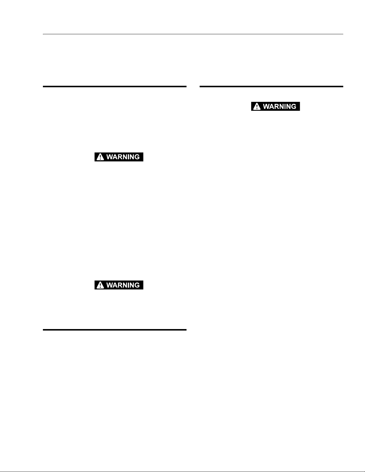
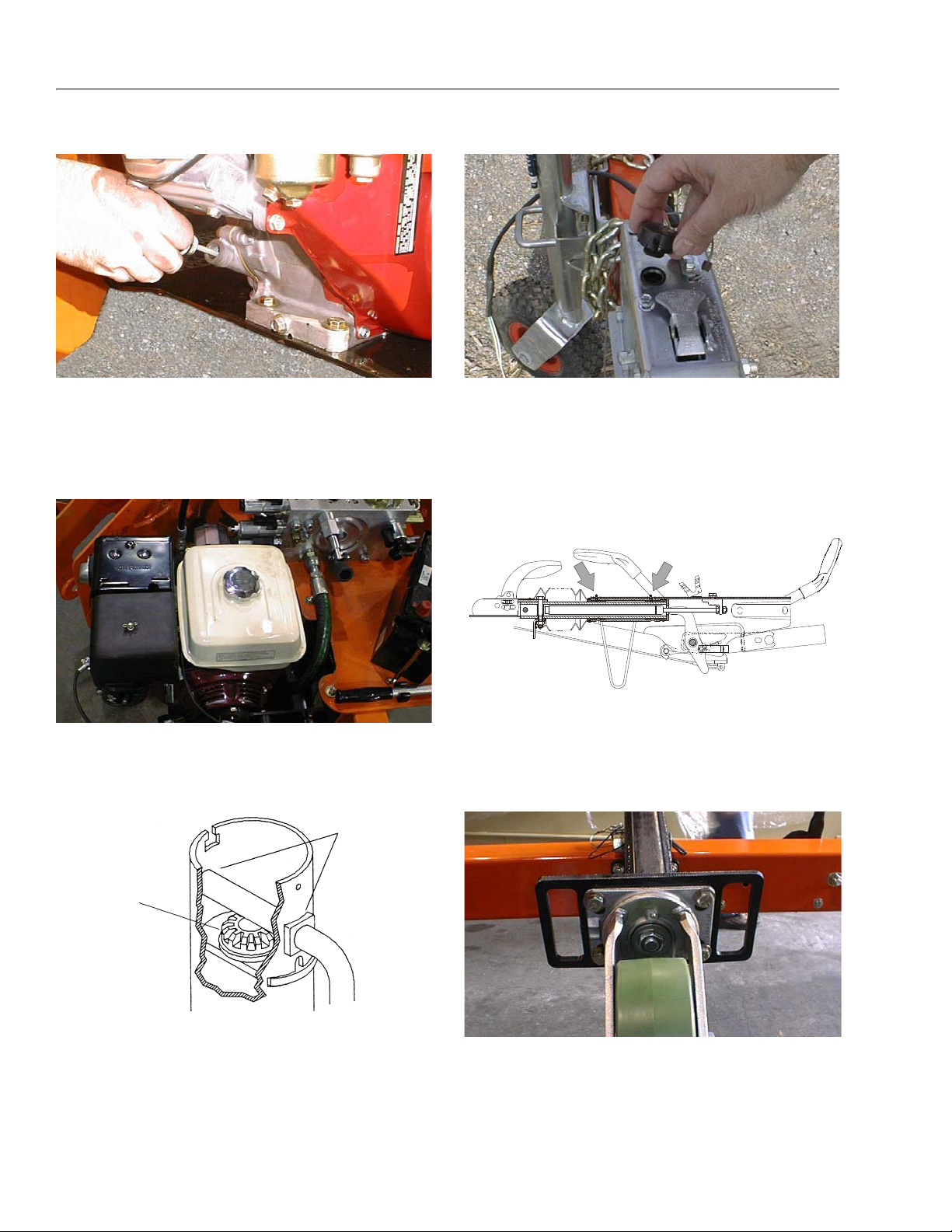
1. Wheel Bearings
2. Hydraulic Oil
3. Hydraulic Filter & Breather
4. Swing Bearing
5. Swing Bearing Teeth
6. Swing Drive
7. Engine
8. Fuel Tank
9. Trailer Jack
10. Surge Brake
11. Coupler & Hitch Ball
12. Jockey Wheel Bearing
Figure 1-1. Operator Maintenance & Lubrication Diagram
1.10 OPERATOR MAINTENANCE &
1. Wheel Bearings
LUBRICATION
NOTE: Lubrication intervals are based on machine opera-
tion under normal conditions. For machines used in
multi shift operations and/or exposed to hostile environments or conditions, lubrication frequencies must
be increased accordingly.
Table 1-11.Lubrication Specifications
KEY SPECIFICATIONS
MPG Multipurpose Grease having a minimum dripping point of
350 degrees F. Excellent water resistance and adhesive
qualities; and being of extreme pressure type (Timken
OK 40 pounds minimum).
EPGL Extreme Pressure Gear Lube (oil) meeting API
Service Classification GL-5 or Mil-Spec Mil-L-
2105.
HO Hydraulic Oil. API Service Classification GL-3,
SAE 10W-20, Viscosity Index 152, e.g. Mobilfluid 424.
EO Engine (crankcase) Oil. Gas - API SF/SG class,
MIL- L-2 10 4. Di es el - A PI CC /C D c la ss, M IL- L2104B/MIL-L-2104C.
OGL Open Gear Lubricant - Mobiltac 375 or equiva-
lent.
1-4 – JLG Lift – 3121198
Lube - MPG
Interval - every 12 months or 12,000 miles
Comments - Refer to Section 3.5, Hubs, Drums,
Wheel Bearings
Page 19
SECTION 1 - SPECIFICATIONS
2. Hydraulic Oil
Lube Point(s) - Fill Cap
Capacity - 4 gal. (15.1 L)
Lube - HO
Interval - Check oil daily, change after, then
every 1200 hours of operation.
3. Hydraulic Filter & Breather
4. Swing Bearing
Lube Point(s) - 1 Grease Fitting
Capacity - As Required
Lube - MPG
Interval - Every month or 50 hours
Comments - Rotate the bearing back and forth
to ensure grease is distributed evenly the whole
way around the bearing.
5. Swing Bearing Teeth
Lube Point(s) - Spray On
Capacity - As Required
Lube - OGL
Interval - Every month or 50 hours
Comments - More frequent lubrication intervals may
be required.
6. Swing Drive
NOTE: The cap securing the filter must be torqued 154 to
170 ft.lbs. (209 to 230.5 Nm).
Lube Point(s) - 2 Grease Fittings
Capacity - As Required
Lube - MPG
Interval - As Required
DO NOT OVERGREASE BEARINGS. OVERGREASING BEARINGS
WILL RESULT IN BLOWING OUTER SEALS IN HOUSING.
Interval - 100 hours
Comments - Change after the first 20 hours, then
every 100 hours of operation.
3121198 – JLG Lift – 1-5
Page 20
SECTION 1 - SPECIFICATIONS
OIL
GREASE
7. Engine
Capacity - See Engine Manual.
Lube - EO, 10W30 API SJ
Interval - Check level daily; change per
manufacturer’s engine manual.
Comments - Adjust final oil level by mark on dipstick
8. Fuel Tank
10. Surge Brake
Lube Point(s) - Fill Cap
Capacity - No more than 1/2
reservoir
Lube - DOT 3 or 4 Brake Fluid
Interval - Check before each tow. Flush the system
yearly or when system is known to be
contaminated
11. Coupler & Hitch Ball
" (13 mm) from top of
Capacity - 1.6 Gal. (6.0 L)
Fuel - Gasoline
Interval - Check periodically during each shift
9. Trailer Jack
Capacity - As necessary
Lube - MPG & EO
Interval - As necessary
Capacity - Coupler 2 Grease Fittings (CE Only);
Hitch Ball
As necessary
Lube - MPG
Interval - As necessary
12. Jockey Wheel Bearing (Drive and Set Option Only)
Lube Point(s) - 1 Grease Fittings
Capacity - As Required
Lube - MPG
Interval - As Required
1-6 – JLG Lift – 3121198
Page 21

SECTION 1 - SPECIFICATIONS
REFERENCE JLG ANEROBIC THREAD LOCKING COMPOUND
JLG P/N Loctite® P/N ND Industries P/N
Description
0100011
242
TM
Vibra-TITE
TM
121
Medium Strength (Blue)
0100019
271
TM
Vibra-TITE
TM
140
High Strength (Red)
0100071
262
TM
Vibra-TITE
TM
131
Medium - High Strength (Red)
Size TPI Bolt Dia
Tensile
Stress Area
Clamp Load
In Sq In LB IN-LB [N.m] IN-LB [N.m] IN-LB [N.m] IN-LB [N.m]
4 40 0.1120 0.00604 380 8 0.9 6 0.7
48 0.1120 0.00661 420 9 1.0 7 0.8
6 32 0.1380 0.00909 580 16 1.8 12 1.4
40 0.1380 0.01015 610 18 2.0 13 1.5
8 32 0.1640 0.01400 900 30 3.4 22 2.5
36 0.1640 0.01474 940 31 3.5 23 2.6
10 24 0.1900 0.01750 1120 43 4.8 32 3.5
32 0.1900 0.02000 1285 49 5.5 36 4
1/4 20 0.2500 0.0318 2020 96 10.8 75 9 105 12
28 0.2500 0.0364 2320 120 13.5 86 10 135 15
In Sq In LB FT-LB [N.m] FT-LB [N.m] FT-LB [N.m] FT-LB [N.m]
5/16 18 0.3125 0.0524 3340 17 23 13 18 19 26 16 22
24 0.3125 0.0580 3700 19 26 14 19 21 29 17 23
3/8 16 0.3750 0.0775 4940 30 41 23 31 35 48 28 38
24 0.3750 0.0878 5600 35 47 25 34 40 54 32 43
7/16 14 0.4375 0.1063 6800 50 68 35 47 55 75 45 61
20 0.4375 0.1187 7550 55 75 40 54 60 82 50 68
1/2 13 0.5000 0.1419 9050 75 102 55 75 85 116 68 92
20 0.5000 0.1599 10700 90 122 65 88 100 136 80 108
9/16 12 0.5625 0.1820 11600 110 149 80 108 120 163 98 133
18 0.5625 0.2030 12950 120 163 90 122 135 184 109 148
5/8 11 0.6250 0.2260 14400 150 203 110 149 165 224 135 183
18 0.6250 0.2560 16300 170 230 130 176 190 258 153 207
3/4 10 0.7500 0.3340 21300 260 353 200 271 285 388 240 325
16 0.7500 0.3730 23800 300 407 220 298 330 449 268 363
7/8 9 0.8750 0.4620 29400 430 583 320 434 475 646 386 523
14 0.8750 0.5090 32400 470 637 350 475 520 707 425 576
1 8 1.0000 0.6060 38600 640 868 480 651 675 918 579 785
12 1.0000 0.6630 42200 700 949 530 719 735 1000 633 858
1 1/8 7 1.1250 0.7630 42300 800 1085 600 813 840 1142 714 968
12 1.1250 0.8560 47500 880 1193 660 895 925 1258 802 1087
1 1/4 7 1.2500 0.9690 53800 1120 1518 840 1139 1175 1598 1009 1368
12 1.2500 1.0730 59600 1240 1681 920 1247 1300 1768 1118 1516
1 3/8 6 1.3750 1.1550 64100 1460 1979 1100 1491 1525 2074 1322 1792
12 1.3750 1.3150 73000 1680 2278 1260 1708 1750 2380 1506 2042
1 1/2 6 1.5000 1.4050 78000 1940 2630 1460 1979 2025 2754 1755 2379
12 1.5000 1.5800 87700 2200 2983 1640 2224 2300 3128 1974 2676
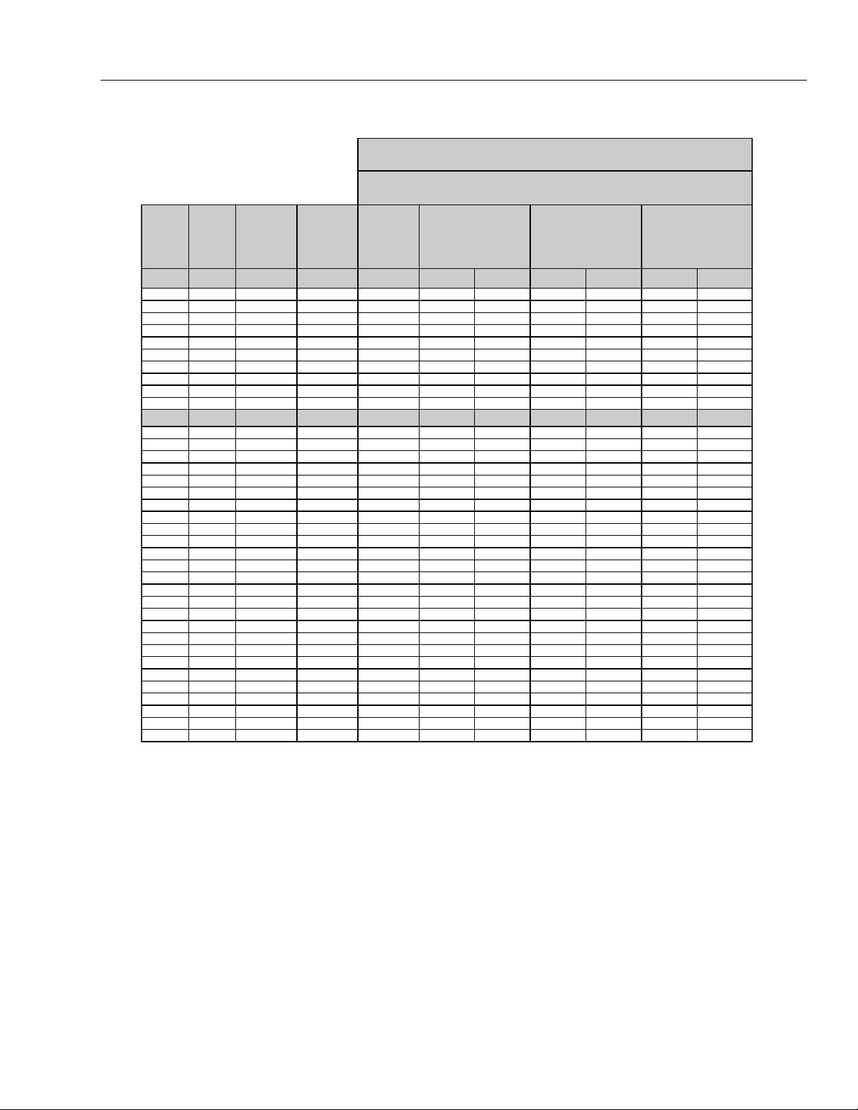
NO. 5000059 REV. J
Values for Zinc Yellow Chromate Fasteners (Ref 4150707)
SAE GRADE 5 BOLTS & GRADE 2 NUTS
Torque
(Dry)
Torque
(Loctite® 262
TM
or Vibra-
TITE
TM
131)
Torque
Lubricated
Torque
(Loctite® 242
TM
or 271
TM
OR Vibra-TIT E
TM
111 or
140)
3. * ASSEMBLY USES HARDENED WASHER
NOTES: 1. THESE TORQUE VALUES DO NOT APPLY TO CADMIUM PLATED FASTENERS
2. ALL TORQUE VALUES ARE STATIC TORQUE MEASURED PER STANDARD AUDIT METHODS TOLERANCE = ±10%
Figure 1-2. Torque Chart (SAE Fasteners - Sheet 1 of 7)
3121198 – JLG Lift – 1-7
Page 22

SECTION 1 - SPECIFICATIONS
Size TPI Bolt Dia
Tensile
Stress Area
Clamp Load
In Sq In
4 40 0.1120 0.00604
48 0.1120 0.00661
6 32 0.1380 0.00909
40 0.1380 0.01015
8 32 0.1640 0.01400
36 0.1640 0.01474
10 24 0.1900 0.01750
32 0.1900 0.02000
1/4 20 0.2500 0.0318
28 0.2500 0.0364
In Sq In
5/16 18 0.3125 0.0524
24 0.3125 0.0580
3/8 16 0.3750 0.0775
24 0.3750 0.0878
7/16 14 0.4375 0.1063
20 0.4375 0.1187
1/2 13 0.5000 0.1419
20 0.5000 0.1599
9/16 12 0.5625 0.1820
18 0.5625 0.2030
5/8 11 0.6250 0.2260
18 0.6250 0.2560
3/4 10 0.7500 0.3340
16 0.7500 0.3730
7/8 9 0.8750 0.4620
14 0.8750 0.5090
1 8 1.0000 0.6060
12 1.0000 0.6630
1 1/8 7 1.1250 0.7630
12 1.1250 0.8560
1 1/4 7 1.2500 0.9690
12 1.2500 1.0730
1 3/8 6 1.3750 1.1550
12 1.3750 1.3150
1 1/2 6 1.5000 1.4050
12 1.5000 1.5800
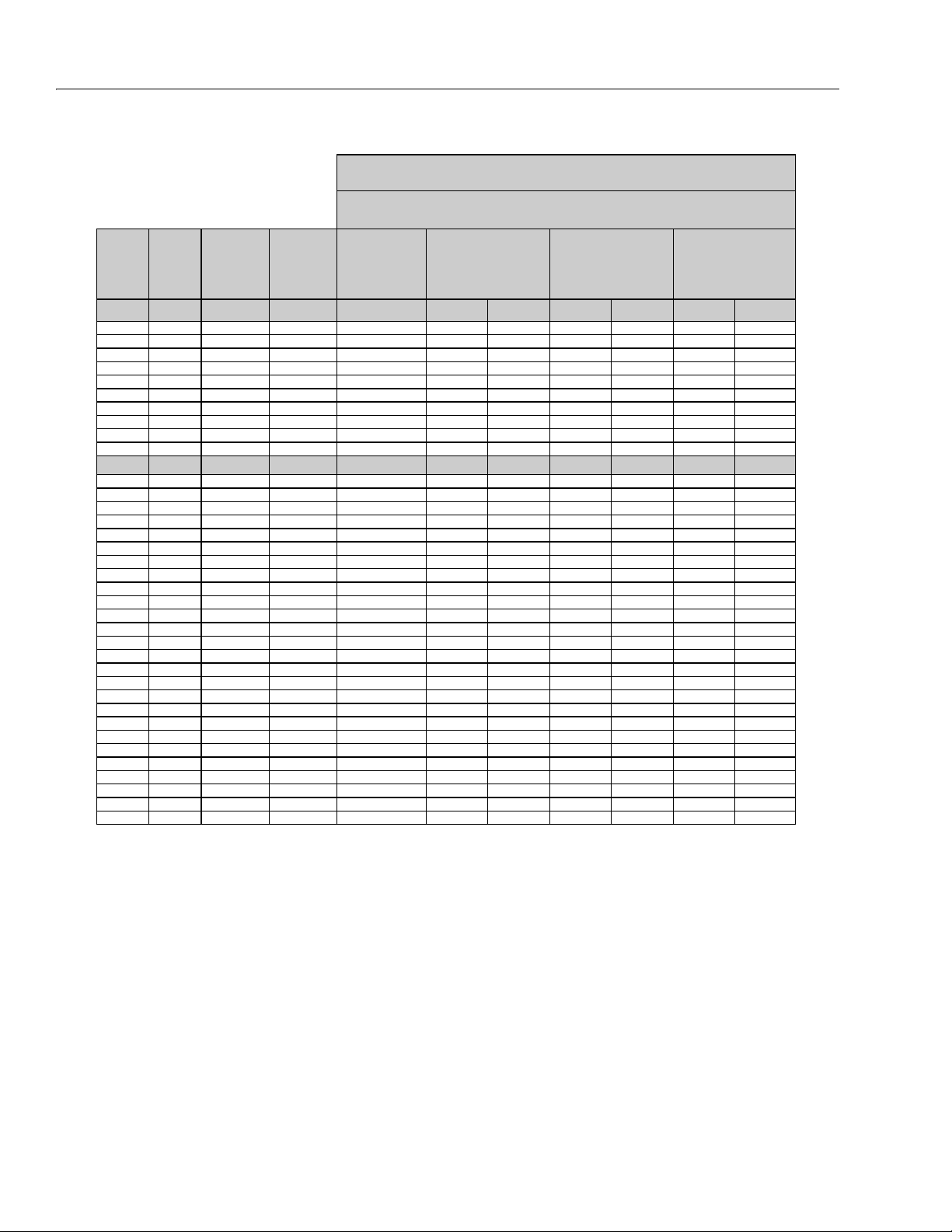
NO. 5000059 REV. J
3. * ASSEMBLY USES HARDENED WASHER
NOTES: 1. THESE TORQUE VALUES DO NOT APPLY TO CADMIUM PLATED FASTENERS
2. ALL TORQUE VALUES ARE STATIC TORQUE MEASURED PER STANDARD AUDIT METHODS TOLERANCE = ±10%
LB IN-LB [N.m] IN-LB [N.m] IN-LB [N.m]
1320 43 5
1580 60 7
1800 68 8
2860 143 16 129 15
3280 164 19 148 17
LB FT-LB [N.m] FT-LB [N.m] FT-LB [N.m
4720 25 35 20 25 20 25
5220 25 35 25 35 20 25
7000456040 553550
7900 50 70 45 60 35 50
9550 70 95 65 90 50 70
10700 80 110 70 95 60 80
12750 105 145 95 130 80 110
14400 120 165 110 150 90 120
16400 155 210 140 190 115 155
18250 170 230 155 210 130 175
20350 210 285 190 260 160 220
23000 240 325 215 290 180 245
30100 375 510 340 460 280 380
33600 420 570 380 515 315 430
41600 605 825 545 740 455 620
45800 670 910 600 815 500 680
51500 860 1170 770 1045 645 875
59700 995 1355 895 1215 745 1015
68700 1290 1755 1160 1580 965 1310
77000 1445 1965 1300 1770 1085 1475
87200 1815 2470 1635 2225 1365 1855
96600 2015 2740 1810 2460 1510 2055
104000 2385 3245 2145 2915 1785 2430
118100 2705 3680 2435 3310 2030 2760
126500 3165 4305 2845 3870 2370 3225
142200 3555 4835 3200 4350 2665 3625
Torque
(Loctite® 242
TM
or 271
TM
OR Vibra-TITE
TM
111 or
140) K=.18
Torque
(Loctite® 262
TM
or Vibra-
TITE
TM
131)
K=0.15
SAE GRADE 8 (HEX HD) BOLTS & GRADE 8 NUTS*
Torque
(Dry or Loctite® 263)
K= 0.20
1-8 – JLG Lift – 3121198
Figure 1-3. Torque Chart (SAE Fasteners - Sheet 2 of 7)
Page 23
Size TPI Bolt Dia
Tensile
Stress Area
Clamp Load
See Note 4
In Sq In LB IN-LB [N.m] IN-LB [N.m] IN-LB [N.m]
4 40 0.1120 0.00604
48 0.1120 0.00661
6 32 0.1380 0.00909
40 0.1380 0.01015
8 32 0.1640 0.01400
36 0.1640 0.01474
10 24 0.1900 0.01750
32 0.1900 0.02000
1/4 20 0.2500 0.0318 2860 122 14 114 13
28 0.2500 0.0364 3280 139 16 131 15
In Sq In LB FT-LB [N.m] FT-LB [N.m] FT-LB [N.m]
5/16 18 0.3125 0.0524 4720 20 25 20 25 20 25
24 0.3125 0.0580 5220 25 35 20 25 20 25
3/8 16 0.3750 0.0775 7000 35 50 35 50 35 50
24 0.3750 0.0878 7900 40 55 40 55 35 50
7/16 14 0.4375 0.1063 9550 60 80 55 75 50 70
20 0.4375 0.1187 10700 65 90 60 80 60 80
1/2 13 0.5000 0.1419 12750 90 120 85 115 80 110
20 0.5000 0.1599 14400 100 135 95 130 90 120
9/16 12 0.5625 0.1820 16400 130 175 125 170 115 155
18 0.5625 0.2030 18250 145 195 135 185 130 175
5/8 11 0.6250 0.2260 20350 180 245 170 230 160 220
18 0.6250 0.2560 23000 205 280 190 260 180 245
3/4 10 0.7500 0.3340 30100 320 435 300 410 280 380
16 0.7500 0.3730 33600 355 485 335 455 315 430
7/8 9 0.8750 0.4620 41600 515 700 485 660 455 620
14 0.8750 0.5090 45800 570 775 535 730 500 680
1 8 1.0000 0.6060 51500 730 995 685 930 645 875
12 1.0000 0.6630 59700 845 1150 795 1080 745 1015
1 1/8 7 1.1250 0.7630 68700 1095 1490 1030 1400 965 1310
12 1.1250 0.8560 77000 1225 1665 1155 1570 1085 1475
1 1/4 7 1.2500 0.9690 87200 1545 2100 1455 1980 1365 1855
12 1.2500 1.0730 96600 1710 2325 1610 2190 1510 2055
1 3/8 6 1.3750 1.1550 104000 2025 2755 1905 2590 1785 2430
12 1.3750 1.3150 118100 2300 3130 2165 2945 2030 2760
1 1/2 6 1.5000 1.4050 126500 2690 3660 2530 3440 2370 3225
12 1.5000 1.5800 142200 3020 4105 2845 3870 2665 3625
NO. 5000059 REV. J
4. CLAMP LOAD LISTED FOR SHCS IS SAME AS GRADE 8 OR CLASS 10.9 AND DOES NOT REPRESENT FULL STRENGTH
CAPABILITY OF SHCS. IF HIGHER LOAD IS REQUIRED, ADDITIONAL TESTING IS REQUIRED.
SOCKET HEAD CAP SCREWS
Magni Coating (Ref 4150701)*
Torque
(Dry) K = .17
Torque
(Loctite® 242
TM
or 271
TM
OR Vibra-TITE
TM
111 or
140 OR Precoat 85®
K=0.16
Torque
(Loctite® 262
TM
or Vibra-
TITE
TM
131)
K=0.15
2. ALL TORQUE VALUES ARE STATIC TORQUE MEASURED PER STANDARD AUDIT METHODS TOLERANCE = ±10%
NOTES: 1. THESE TORQUE VALUES DO NOT APPLY TO CADMIUM PLATED FASTENERS
*3. ASSEMBLY USES HARDENED WASHER OR FASTENER IS PLACED AGAINST PLATED STEEL OR RAW ALUMINUM
SECTION 1 - SPECIFICATIONS
3121198 – JLG Lift – 1-9
Figure 1-4. Torque Chart (SAE Fasteners - Sheet 3 of 7)
Page 24
SECTION 1 - SPECIFICATIONS
Size TPI Bolt Dia
Tensile
Stress Area
Clamp Load
See Note 4
In Sq In LB IN-LB [N.m] IN-LB [N.m] IN-LB [N.m]
4 40 0.1120 0.00604
48 0.1120 0.00661
6 32 0.1380 0.00909
40 0.1380 0.01015
8 32 0.1640 0.01400
36 0.1640 0.01474
10 24 0.1900 0.01750
32 0.1900 0.02000
1/4 20 0.2500 0.0318 2860 143 16 129 15
28 0.2500 0.0364 3280 164 19 148 17
In Sq In LB FT-LB [N.m] FT-LB [N.m] FT-LB [N.m]
5/16 18 0.3125 0.0524 4720 25 35 20 25 20 25
24 0.3125 0.0580 5220 25 35 25 35 20 25
3/8 16 0.3750 0.0775 7000 45 60 40 55 35 50
24 0.3750 0.0878 7900 50 70 45 60 35 50
7/16 14 0.4375 0.1063 9550 70 95 65 90 50 70
20 0.4375 0.1187 10700 80 110 70 95 60 80
1/2 13 0.5000 0.1419 12750 105 145 95 130 80 110
20 0.5000 0.1599 14400 120 165 110 150 90 120
9/16 12 0.5625 0.1820 16400 155 210 140 190 115 155
18 0.5625 0.2030 18250 170 230 155 210 130 175
5/8 11 0.6250 0.2260 20350 210 285 190 260 160 220
18 0.6250 0.2560 23000 240 325 215 290 180 245
3/4 10 0.7500 0.3340 30100 375 510 340 460 280 380
16 0.7500 0.3730 33600 420 570 380 515 315 430
7/8 9 0.8750 0.4620 41600 605 825 545 740 455 620
14 0.8750 0.5090 45800 670 910 600 815 500 680
1 8 1.0000 0.6060 51500 860 1170 775 1055 645 875
12 1.0000 0.6630 59700 995 1355 895 1215 745 1015
1 1/8 7 1.1250 0.7630 68700 1290 1755 1160 1580 965 1310
12 1.1250 0.8560 77000 1445 1965 1300 1770 1085 1475
1 1/4 7 1.2500 0.9690 87200 1815 2470 1635 2225 1365 1855
12 1.2500 1.0730 96600 2015 2740 1810 2460 1510 2055
1 3/8 6 1.3750 1.1550 104000 2385 3245 2145 2915 1785 2430
12 1.3750 1.3150 118100 2705 3680 2435 3310 2030 2760
1 1/2 6 1.5000 1.4050 126500 3165 4305 2845 3870 2370 3225
12 1.5000 1.5800 142200 3555 4835 3200 4350 2665 3625
NO. 5000059 REV. J
4. CLAMP LOAD LISTED FOR SHCS IS SAME AS GRADE 8 OR CLASS 10.9 AND DOES NOT REPRESENT FULL STRENGTH
CAPABILITY OF SHCS. IF HIGHER LOAD IS REQUIRED, ADDITIONAL TESTING IS REQUIRED.
SOCKET HEAD CAP SCREWS
Torque
(Dry)
K = .20
Torque
(Loctite® 242TM or 271
TM
OR Vibra-TITE
TM
111 or
140 OR Precoat 85®
K=0.18
Zinc Yellow Chromate Fasteners (Ref 4150707)*
2. ALL TORQUE VALUES ARE STATIC TORQUE MEASURED PER STANDARD AUDIT METHODS TOLERANCE = ±10%
NOTES: 1. THESE TORQUE VALUES DO NOT APPLY TO CADMIUM PLATED FASTENERS
*3. ASSEMBLY USES HARDENED WASHER OR FASTENER IS PLACED AGAINST PLATED STEEL OR RAW ALUMINUM
Torque
(Loctite® 262
TM
or Vibra-
TITE
TM
131)
K=0.15
1-10 – JLG Lift – 3121198
Figure 1-5. Torque Chart (SAE Fasteners - Sheet 4 of 7)
Page 25
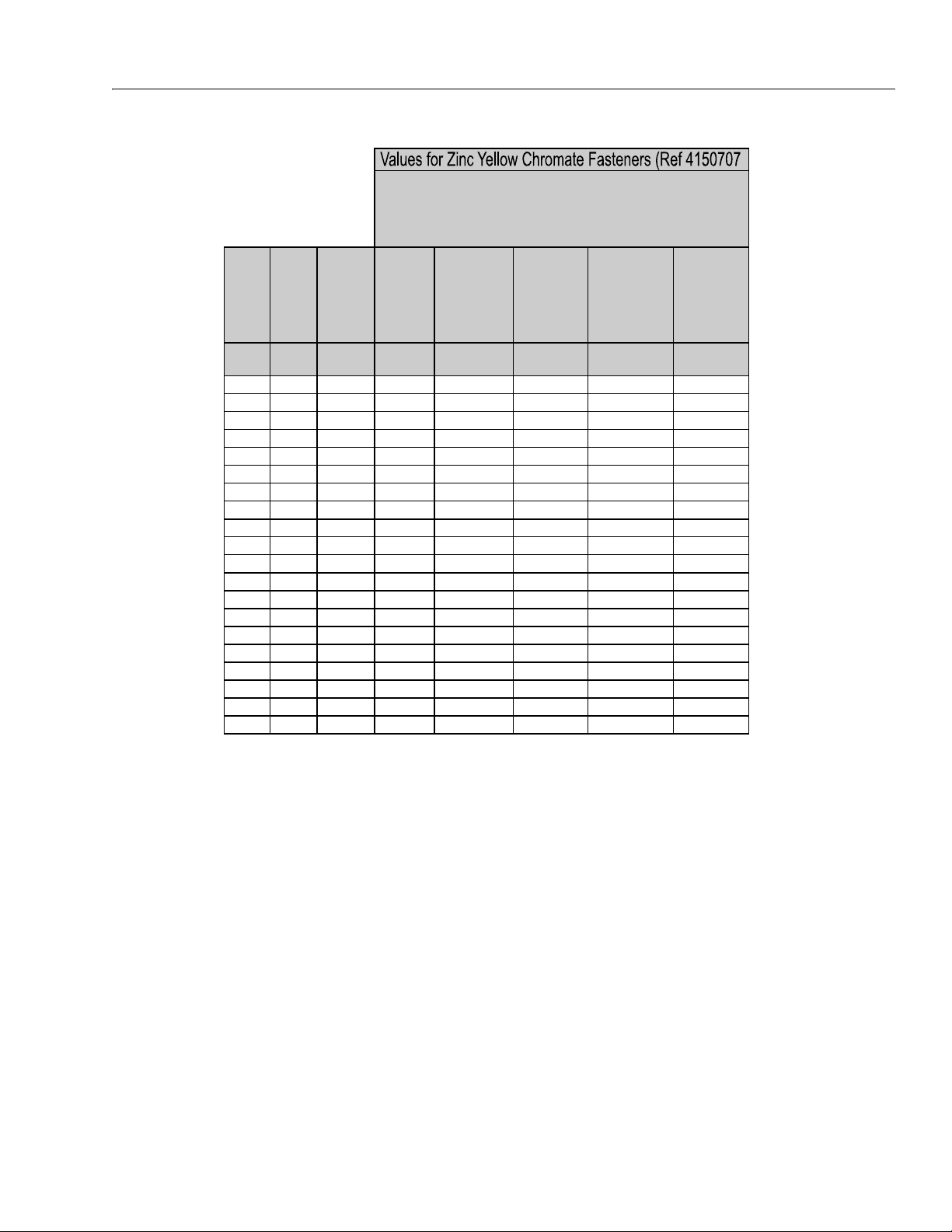
SECTION 1 - SPECIFICATIONS
Size PITCH
Tensile
Stress
Area
Clamp
Load
Torque
(Dry or Loctite®
263
TM
)
Torque
(Lub)
Torque
(Loctite® 262
TM
OR Vibra-
TITE
TM
131)
Torque
(Loctite®
242
TM
or 271
TM
OR Vibra-
TITE
TM
111 or
140)
Sq mm KN [N.m] [N.m] [N.m] [N.m]
3 0.5 5.03 2.19 1.3 1.0 1.2 1.4
3.5 0.6 6.78 2.95 2.1 1.6 1.9 2.3
4 0.7 8.78 3.82 3.1 2.3 2.8 3.4
5 0.8 14.20 6.18 6.2 4.6 5.6 6.8
6 1 20.10 8.74 11 7.9 9.4 12
7 1 28.90 12.6 18 13 16 19
8 1.25 36.60 15.9 26 19 23 28
10 1.5 58.00 25.2 50 38 45 55
12 1.75 84.30 36.7 88 66 79 97
14 2 115 50.0 140 105 126 154
16 2 157 68.3
219 164 197 241
18 2.5 192 83.5 301 226 271 331
20 2.5 245 106.5 426 320 383 469
22 2.5 303 132.0 581 436 523 639
24 3 353 153.5 737 553 663 811
27 3 459 199.5 1080 810 970 1130
30 3.5 561 244.0 1460 1100 1320 1530
33 3.5 694 302.0 1990 1490 1790 2090
36 4 817 355.5 2560 1920 2300 2690
42 4.5 1120 487.0 4090 3070 3680 4290
4. CLAMP LOAD LISTED FOR SHCS IS SAME AS GRADE 8 OR CLASS 10.9 AND DOES NOT
REPRESENT FULL STRENGTH CAPABILITY OF SHCS. IF HIGHER LOAD IS REQUIRED,
ADDITIONAL TESTING IS REQUIRED.
*3. ASSEMBLY USES HARDENED WASHER OR FASTENER IS PLACED AGAINST PLATED
STEEL OR RAW ALUMINUM
CLASS 8.8 METRIC BOLTS
CLASS 8 METRIC NUTS
NOTES: 1. THESE TORQUE VALUES DO NOT APPLY TO CADMIUM PLATED FASTENERS
2. ALL TORQUE VALUES ARE STATIC TORQUE MEASURED PER STANDARD AUDIT
METHODS TOLERANCE = ±10%
NO. 5000059 REV. J
Figure 1-6. Torque Chart (METRIC Fasteners - Sheet 5 of 7)
3121198 – JLG Lift – 1-11
Page 26
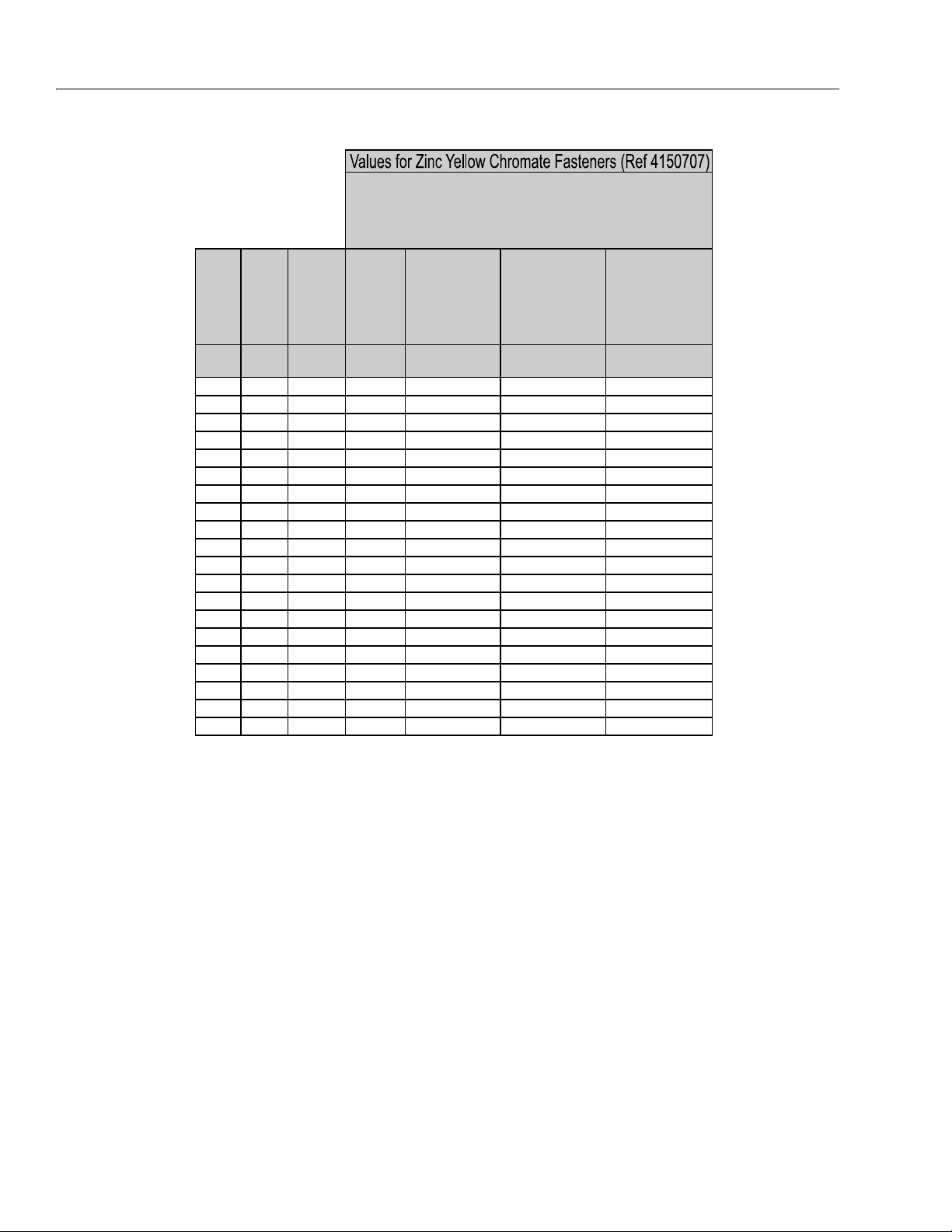
SECTION 1 - SPECIFICATIONS
Size PITCH
Tensile
Stress
Area
Clamp
Load
Torque
(Dry or Loctite®
263
TM
)
K = 0.20
Torque
(Lub OR Loctite®
242
TM
or 271TM OR
Vibra-TITE
TM
111 or
140)
K= 0.18
Torque
(Loctite® 262
TM
OR
Vibra-TITE
TM
131)
K=0.15
Sq mm KN [N.m] [N.m] [N.m]
3 0.5 5.03 3.13
3.5 0.6 6.78 4.22
4 0.7 8.78 5.47
5 0.8 14.20 8.85
6 1 20.10 12.5
7 1 28.90 18.0 25.2 22.7 18.9
8 1.25 36.60 22.8 36.5 32.8 27.4
10 1.5 58.00 36.1 70 65 55
12 1.75 84.30 52.5 125 115 95
14 2 115 71.6 200 180 150
16 2 157 97.8
315 280 235
18 2.5 192 119.5 430 385 325
20 2.5 245 152.5 610 550 460
22 2.5 303 189.0 830 750 625
24 3 353 222.0 1065 960 800
27 3 459 286.0 1545 1390 1160
30 3.5 561 349.5 2095 1885 1575
33 3.5 694 432.5 2855 2570 2140
36 4 817 509.0 3665 3300 2750
42 4.5 1120 698.0 5865 5275 4395
CLASS 10.9 METRIC BOLTS
CLASS 10 METRIC NUTS
CLASS 12.9 SOCKET HEAD CAP SCREWS M3 - M5*
4. CLAMP LOAD LISTED FOR SHCS IS SAME AS GRADE 8 OR CLASS 10.9 A ND DOES NOT
REPRESENT FULL STRENGTH CAPABILITY OF SHCS. IF HIGHER LOAD IS REQUIRED,
ADDITIONAL TESTING IS REQUIRED.
*3. ASSEMBLY USES HARDENED WASHER OR FASTENER IS PLACED AGAINST PLATED
STEEL OR RAW ALUMINUM
NOTES: 1. THESE TORQUE VALUES DO NOT APPLY TO CADMIUM PLATED FASTENERS
2. ALL TORQUE VALUES ARE STATIC TORQUE MEASURED PER STANDARD AUDIT
METHODS TOLERANCE = ±10%
NO. 5000059 REV. J
Figure 1-7. Torque Chart (METRIC Fasteners - Sheet 6 of 7)
1-12 – JLG Lift – 3121198
Page 27
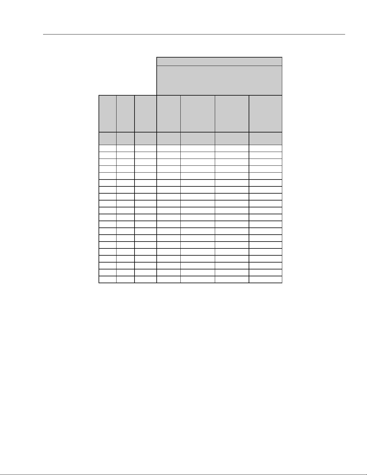
SECTION 1 - SPECIFICATIONS
Size PITCH
Tensile
Stress
Area
Clamp Load
See Note 4
Torque
(Dry or Loctite®
263
TM
)
K = .17
Torque
(Lub OR Loctite®
242
TM
or 271
TM
OR Vibra-TITE
TM
111 or 140)
K = .16
Torque
(Loctite® 262
TM
OR Vibra-TITE
TM
131)
K = .15
Sq mm kN [N.m] [N.m] [N.m]
30.55.03
3.5 0.6 6.78
40.78.78
50.814.20
6120.1012.5 13 12 11
7128.9018.0 21 20 19
8 1.25 36.60 22.8 31 29 27
10 1.5 58.00 36.1 61 58 54
12 1.75 84.30 52.5 105 100 95
14 2 115 71.6 170 160 150
16 2 157
97.8 265 250 235
18 2.5 192 119.5 365 345 325
20 2.5 245 152.5 520 490 460
22 2.5 303 189.0 705 665 625
24 3 353 220.0 900 845 790
27 3 459 286.0 1315 1235 1160
30 3.5 561 349.5 1780 1680 1575
33 3.5 694 432.5 2425 2285 2140
36 4 817 509.0 3115 2930 2750
42 4.5 1120 698.0 4985 4690 4395
CLASS 12.9 SOCKET HEAD CAP SCREWS
M6 AND ABOVE*
4. CLAMP LOAD LISTED FOR SHCS IS SAME AS GRADE 8 OR CLASS 10.9 AND DOES NOT
REPRESENT FULL STRENG TH CAPABILITY OF SHCS. IF HIGHER LOAD IS REQUIRED,
ADDITIONAL TESTING IS REQUIRED.
*3. ASSEMBLY USES HARDENED WASHER OR FASTENER IS PLACED AGAINST PLATED
STEEL OR RAW ALUMINUM
NOTES: 1. THESE TORQUE VALUES DO NOT APPLY TO CADMIUM PLATED FASTENERS
2. ALL TORQUE VALUES ARE STATIC TORQUE MEASURED PER STANDARD AUDIT
METHODS TOLERANCE = ±10%
NO. 5000059 REV. J
Magni Coating (Ref 4150701)*
3121198 – JLG Lift – 1-13
Figure 1-8. Torque Chart (METRIC Fasteners - Sheet 7 of 7)
Page 28

SECTION 1 - SPECIFICATIONS
NOTES:
1-14 – JLG Lift – 3121198
Page 29

SECTION 2. GENERAL
SECTION 2 - GENERAL
2.1 MACHINE PREPARATION, INSPECTION, AND MAINTENANCE
General
This section provides the necessary information needed
by those personnel that are responsible to place the
machine in operation readiness and maintain its safe
operating condition. For maximum service life and safe
operation, ensure that all the necessary inspections and
maintenance have been completed before placing the
machine into service.
Preparation, Inspection, and Maintenance
It is important to establish and conform to a comprehensive inspection and preventive maintenance program. The
following table outlines the periodic machine inspections
and maintenance recommended by JLG Industries, Inc.
Consult your national, regional, or local regulations for further requirements for aerial work platforms. The frequency
of inspections and maintenance must be increased as
environment, severity and frequency of usage requires.
Pre-Start Inspection
It is the User’s or Operator’s primary responsibility to perform a Pre-Start Inspection of the machine prior to use
daily or at each change of operator. Reference the Operator’s and Safety Manual for completion procedures for the
Pre-Start Inspection. The Operator and Safety Manual
must be read in its entirety and understood prior to performing the Pre-Start Inspection.
Reference the JLG Pre-Delivery and Frequent Inspection
Form and the Inspection and Preventative Maintenance
Schedule for items requiring inspection during the performance of these inspections. Reference the appropriate
areas of this manual for servicing and maintenance procedures.
Annual Machine Inspection
The Annual Machine Inspection must be performed by a
Factory-Certified Service Technician on an annual basis,
no later than thirteen (13) months from the date of the
prior Annual Machine Inspection. JLG Industries, Inc. recognizes a Factory-Certified Service Technician as a person who has successfully completed the JLG Service
Training School for the subject JLG product model. Reference the machine Service and Maintenance Manual and
appropriate JLG inspection form for performance of this
inspection.
Reference the JLG Annual Machine Inspection Form and
the Inspection and Preventative Maintenance Schedule for
items requiring inspection during the performance of this
inspection. Reference the appropriate areas of this manual for servicing and maintenance procedures.
For the purpose of receiving safety-related bulletins, it is
important that JLG Industries, Inc. has updated ownership
information for each machine. When performing each
Annual Machine Inspection, notify JLG Industries, Inc. of
the current machine ownership.
Preventative Maintenance
Pre-Delivery Inspection and Frequent Inspection
The Pre-Delivery Inspection and Frequent Inspection shall
be performed by a qualified JLG equipment mechanic.
JLG Industries, Inc. recognizes a qualified JLG equipment
mechanic as a person who, by possession of a recognized degree, certificate, extensive knowledge, training, or
experience, has successfully demonstrated the ability and
proficiency to service, repair, and maintain the subject
JLG product model.
The Pre-Delivery Inspection and Frequent Inspection procedures are performed in the same manner, but at different times. The Pre-Delivery Inspection shall be performed
prior to each sale, lease, or rental delivery. The Frequent
Inspection shall be accomplished for each machine in service for 3 months or 150 hours (whichever comes first);
out of service for a period of more than 3 months; or when
purchased used. The frequency of this inspection must be
increased as environment, severity and frequency of
usage requires.
In conjunction with the specified inspections, maintenance shall be performed by a qualified JLG equipment
mechanic. JLG Industries, Inc. recognizes a qualified JLG
equipment mechanic as a person who, by possession of a
recognized degree, certificate, extensive knowledge, training, or experience, has successfully demonstrated the
ability and proficiency to service, repair, and maintain the
subject JLG product model.
Reference the Preventative Maintenance Schedule and
the appropriate areas of this manual for servicing and
maintenance procedures. The frequency of service and
maintenance must be increased as environment, severity
and frequency of usage requires.
3121198 – JLG Lift – 2-1
Page 30

SECTION 2 - GENERAL
Table 2-1. Inspection and Maintenance
Type Frequency
Pre-Start Inspection Prior to use each day; or
At each Operator change.
Pre-Delivery
Inspection
Frequent Inspection In service for 3 months or 150 hours, which-
Annual Machine
Inspection
Preventative
Maintenance
Prior to each sale, lease, or
rental delivery.
ever comes first; or
Out of service for a period of more than 3
months; or
Purchased used.
Annually, no later than 13 months from the
date of the prior inspection.
At intervals as specified in the Service and
Maintenance Manual.
2.2 SERVICE AND GUIDELINES
General
The following information is provided to assist you in the
use and application of servicing and maintenance procedures contained in this book.
Safety and Workmanship
Your safety, and that of others, is the first consideration
when engaging in the maintenance of equipment. Always
be conscious of weight. Never attempt to move heavy
parts without the aid of a mechanical device. Do not allow
heavy objects to rest in an unstable position. When raising
a portion of the equipment, ensure that adequate support
is provided.
Cleanliness
1. The most important single item in preserving the
long service life of a machine is to keep dirt and foreign materials out of the vital components. Precautions have been taken to safeguard against this.
Shields, covers, seals, and filters are provided to
keep air, fuel, and oil supplies clean; however, these
items must be maintained on a scheduled basis in
order to function properly.
Primary
Responsibility
User or Operator User or Operator Operator and Safety Ma nual
Owner, Dealer, or User Qualified JLG
Owner, Dealer, or User Qualified JLG
Owner, Dealer, or User Factory-Certified
Owner, Dealer, or User Qualified JLG
2. At any time when air, fuel, or oil lines are disconnected, clear adjacent areas as well as the openings
and fittings themselves. As soon as a line or component is disconnected, cap or cover all openings to
prevent entry of foreign matter.
3. Clean and inspect all parts during servicing or maintenance, and assure that all passages and openings
are unobstructed. Cover all parts to keep them
clean. Be sure all parts are clean before they are
installed. New parts should remain in their containers until they are ready to be used.
Service
Qualification
Mechanic
Mechanic
Service Technician
Mechanic
Reference
Service and Maintenance
Manual and applicable JLG
inspection form.
Service and Maintenance
Manual and applicable JLG
inspection form.
Service and Maintenance
Manual and applicable JLG
inspection form.
Service and Maintenance
Manual
Components Removal and Installation
1. Use adjustable lifting devices, whenever possible, if
mechanical assistance is required. All slings (chains,
cables, etc.) should be parallel to each other and as
near perpendicular as possible to top of part being
lifted.
2. Should it be necessary to remove a component on
an angle, keep in mind that the capacity of an eyebolt or similar bracket lessens, as the angle between
the supporting structure and the component
becomes less than 90 degrees.
3. If a part resists removal, check to see whether all
nuts, bolts, cables, brackets, wiring, etc., have been
removed and that no adjacent parts are interfering.
2-2 – JLG Lift – 3121198
Page 31

SECTION 2 - GENERAL
Component Disassembly and Reassembly
When disassembling or reassembling a component, complete the procedural steps in sequence. Do not partially
disassemble or assemble one part, then start on another.
Always recheck your work to assure that nothing has been
overlooked. Do not make any adjustments, other than
those recommended, without obtaining proper approval.
Pressure-Fit Parts
When assembling pressure-fit parts, use an anti-seize or
molybdenum disulfide base compound to lubricate the
mating surface.
Bearings
1. When a bearing is removed, cover it to keep out dirt
and abrasives. Clean bearings in nonflammable
cleaning solvent and allow to drip dry. Compressed
air can be used but do not spin the bearing.
2. Discard bearings if the races and balls (or rollers)
are pitted, scored, or burned.
3. If bearing is found to be serviceable, apply a light
coat of oil and wrap it in clean (waxed) paper. Do not
unwrap reusable or new bearings until they are
ready to install.
4. Lubricate new or used serviceable bearings before
installation. When pressing a bearing into a retainer
or bore, apply pressure to the outer race. If the bearing is to be installed on a shaft, apply pressure to the
inner race.
Gaskets
Check that holes in gaskets align with openings in the
mating parts. If it becomes necessary to hand-fabricate a
gasket, use gasket material or stock of equivalent material
and thickness. Be sure to cut holes in the right location, as
blank gaskets can cause serious system damage.
2. Unless specific torque requirements are given within
the text, standard torque values should be used on
heat-treated bolts, studs, and steel nuts, in accordance with recommended shop practices. (See
Torque Chart Section 1.)
Hydraulic Lines and Electrical Wiring
Clearly mark or tag hydraulic lines and electrical wiring, as
well as their receptacles, when disconnecting or removing
them from the unit. This will assure that they are correctly
reinstalled.
Hydraulic System
1. Keep the system clean. If evidence of metal or rubber particles are found in the hydraulic system, drain
and flush the entire system.
2. Disassemble and reassemble parts on clean work
surface. Clean all metal parts with non-flammable
cleaning solvent. Lubricate components, as
required, to aid assembly.
Lubrication
Service applicable components with the amount, type,
and grade of lubricant recommended in this manual, at
the specified intervals. When recommended lubricants are
not available, consult your local supplier for an equivalent
that meets or exceeds the specifications listed.
Battery
Clean battery, using a non-metallic brush and a solution of
baking soda and water. Rinse with clean water. After
cleaning, thoroughly dry battery and coat terminals with
an anti corrosion compound.
Lubrication and Servicing
Components and assemblies requiring lubrication and
servicing are shown in the Lubrication Chart in Section 1.
Bolt Usage and Torque Application
1. Use bolts of proper length. A bolt which is too long
will bottom before the head is tight against its related
part. If a bolt is too short, there will not be enough
thread area to engage and hold the part properly.
When replacing bolts, use only those having the
same specifications of the original, or one which is
equivalent.
3121198 – JLG Lift – 2-3
Page 32

SECTION 2 - GENERAL
2.3 LUBRICATION AND INFORMATION
Hydraulic System
1. The primary enemy of a hydraulic system is contamination. Contaminants enter the system by various
means, e.g., using inadequate hydraulic oil, allowing
moisture, grease, filings, sealing components, sand,
etc., to enter when performing maintenance, or by
permitting the pump to cavitate due to insufficient
system warm-up or leaks in the pump supply (suction) lines.
2. The design and manufacturing tolerances of the
component working parts are very close, therefore,
even the smallest amount of dirt or foreign matter
entering a system can cause wear or damage to the
components and generally results in faulty operation. Every precaution must be taken to keep
hydraulic oil clean, including reserve oil in storage.
Hydraulic system filters should be checked,
cleaned, and/or replaced as necessary, at the specified intervals required in the Lubrication Chart in
Section 1. Always examine filters for evidence of
metal particles.
3. Cloudy oils indicate a high moisture content which
permits organic growth, resulting in oxidation or corrosion. If this condition occurs, the system must be
drained, flushed, and refilled with clean oil.
4. It is not advisable to mix oils of different brands or
types, as they may not contain the same required
additives or be of comparable viscosities. Good
grade mineral oils, with viscosities suited to the
ambient temperatures in which the machine is operating, are recommended for use.
NOTE: Metal particles may appear in the oil or filters of new
machines due to the wear-in of meshing components.
Hydraulic Oil
F (-29° C). However, use of this oil will give poor performance at temperatures above 120° F (49°C). Systems using DTE 13 oil should not be operated at
temperatures above 200° F (94° C) under any condition.
Changing Hydraulic Oil
1. Filter elements must be changed after the first 50
hours of operation and every 300 hours thereafter. If
it is necessary to change the oil, use only those oils
meeting or exceeding the specifications appearing
in this manual. If unable to obtain the same type of
oil supplied with the machine, consult local supplier
for assistance in selecting the proper equivalent.
Avoid mixing petroleum and synthetic base oils. JLG
Industries recommends changing the hydraulic oil
annually.
2. Use every precaution to keep the hydraulic oil clean.
If the oil must be poured from the original container
into another, be sure to clean all possible contaminants from the service container. Always clean the
mesh element of the filter and replace the cartridge
any time the system oil is changed.
3. While the unit is shut down, a good preventive maintenance measure is to make a thorough inspection
of all hydraulic components, lines, fittings, etc., as
well as a functional check of each system, before
placing the machine back in service.
Lubrication Specifications
Specified lubricants, as recommended by the component
manufacturers, are always the best choice, however,
multi-purpose greases usually have the qualities which
meet a variety of single purpose grease requirements.
Should any question arise, regarding the use of greases in
maintenance stock, consult your local supplier for evaluation. Refer to Section 1 for an explanation of the lubricant
key designations appearing in the Lubrication Chart.
1. Refer to Section 1 for recommendations for viscosity
ranges.
2. JLG recommends Mobilfluid 424 hydraulic oil, which
has an SAE viscosity of 10W-30 and a viscosity
index of 152.
NOTE: Start-up of hydraulic system with oil temperatures
below -15 degrees F (-26 degrees C) is not recommended. If it is necessary to start the system in a
sub-zero environment, it will be necessary to heat
the oil with a low density, 100VAC heater to a minimum temperature of -15 degrees F (-26 degrees C).
3. The only exception to the above is to drain and fill
the system with Mobil DTE 13 oil or its equivalent.
This will allow start up at temperatures down to -20 °
2-4 – JLG Lift – 3121198
Page 33

SECTION 2 - GENERAL
2.4 CYLINDER DRIFT TEST
Maximum acceptable cylinder drift is to be measured
using the following methods.
Platform Drift
Measure the drift of the platform to the ground. Lower
booms (if equipped) slightly elevated, main boom fully
extended with the rated load in the platform and power off.
Maximum allowable drift is 2 inches (5 cm) in 10 minutes.
If the machine does not pass this test, proceed with the
following.
Cylinder Drift
Table 2-2. Cylinder Drift
Cylinder Bore Diameter
inches mm inches mm
3 76.2 0.026 0.66
3.5 89 0.019 0.48
4 101.6 0.015 0.38
5 127 0.009 0.22
6 152.4 0.006 0.15
7 177.8 0.005 0.13
8 203.2 0.0038 0.10
9 228.6 0.0030 0.08
Drift is to be measured at the cylinder rod with a calibrated
dial indicator. The cylinder oil must be at ambient temperature and temperature stabilized.
The cylinder must have the normal load, which is the normal platform load applied.
If the cylinder passes this test, it is acceptable.
NOTE: This information is based on 6 drops per minute cyl-
inder leakage.
Max. Acceptable Drift
in 10 Minutes
2.5 PINS AND COMPOSITE BEARING REPAIR GUIDELINES
Filament wound bearings.
1. Pinned joints should be disassembled and
inspected if the following occurs:
a. Excessive sloppiness in joints.
b. Noise originating from the joint during operation.
2. Filament wound bearings should be replaced if any
of the following is observed:
a. Frayed or separated fibers on the liner surface.
b. Cracked or damaged liner backing.
c. Bearings that have moved or spun in their hous-
ing.
d. Debris embedded in liner surface.
3. Pins should be replaced if any of the following is
observed (pin should be properly cleaned prior to
inspection):
a. Detectable wear in the bearing area.
b. Flaking, pealing, scoring, or scratches on the pin
surface.
c. Rusting of the pin in the bearing area.
4. Re-assembly of pinned joints using filament wound
bearings.
a. Housing should be blown out to remove all dirt
and debris...bearings and bearing housings
must be free of all contamination.
b. Bearing / pins should be cleaned with a solvent
to remove all grease and oil...filament wound
bearing are a dry joint and should not be lubricated unless otherwise instructed (i.e. sheave
pins).
c. Pins should be inspected to ensure it is free of
burrs, nicks, and scratches which would damage the bearing during installation and operation.
3121198 – JLG Lift – 2-5
Page 34

SECTION 2 - GENERAL
2.6 WELDING ON JLG EQUIPMENT
NOTE: This instruction applies to repairs, or modifications to
the machine and to welding performed from the
machine on an external structure, or component,
Do the Following When Welding on JLG Equipment
• Disconnect the battery.
• Disconnect the moment pin connection (where fitted)
• Ground only to structure being welded.
Do NOT Do the Following When Welding on JLG Equipment
• Ground on frame and weld on any other area than the
chassis.
• Ground on turntable and weld on any other area than
the turntable.
• Ground on the platform/support and weld on any other
area than the platform/support.
• Ground on a specific boom section and weld on any
other area than that specific boom section.
• Allow pins, wear pads, wire ropes, bearings, gearing,
seals, valves, electrical wiring, or hoses to be between
the grounding position and the welded area.
FAILURE TO COMPLY WITH THE ABOVE REQUIREMENTS MAY
RESULT IN COMPONENT DAMAGE (I.E. ELECTRONIC MODULES,
SWING BEARING, COLLECTOR RING, BOOM WIRE ROPES ETC.)
2-6 – JLG Lift – 3121198
Page 35

Table 2-3. Maintenance Schedule
SECTION 2 - GENERAL
INTERVAL
Item/Function Method Break-In
Wheel Lugs
1
Tighten to specified torque rating XX
Every 3000 Miles
or 3 Months
Every 6000 Miles
Coupler Ball Check for unusual wear X
Safety Chains Check for unusual wear in links X
Brakes
Brake Fluid
2
3
Check general operation and proper adjustment XX
Check reservoir X
Breakaway Check ca ble and all components X
Suspension Check for worn components or broken springs X
Welds Check welds for cracks or separations X
Floor, hinges, door and
dividers
Inspect - repair or replace damaged, worn or broken
Wash both sides. Wash floor.
X
parts.
Rotate every 5000 miles
Tires
Inspect tread and sidewalls thoroughly
replace tire when treads are worn, when sidewall
has a bulge, or sidewall is worn.
Brakes, electric
Magnets
Controller (in tow vehicle)
Check power output (amperage) and modulation
Check wear and current draw
Roof vents, windows Clean dirt buildup, lubrica te hinges and slides X
or 6 Months
X
X
Every 12,000
Miles or 1 year
Brakes - All types Check for scoring and wearing X
Jack, drop leg Grease gears at top X
Frame members/ welds Inspect all frames members, bolts and rivets. repair
or replace damaged worn or broken parts
X
Inspect all welds. repair as needed
Wheels - Sealed bearings
(hubs), Unsealed bear-
ings, Rims
Check and confirm free running. Replace if not.
(sealed bearings are not serviceable)
Disassemble/inspect/assemble and repack.
X
replace promptly, if immersed in water.
Inspect for cracks and dents. Replace as needed.
Axle attachment bolts Check by dealer X
NOTE: 1 = Retighten when new and at the first 10, 25 and 50 miles
2 = Adjust after first 200 miles, 3000 mile intervals or as use requires.
3 = 1000 miles or 1 month when used in hot and dry environment.
3121198 – JLG Lift – 2-7
Page 36

SECTION 2 - GENERAL
NOTES:
2-8 – JLG Lift – 3121198
Page 37

SECTION 3 - CHASSIS & TURNTABLE
SECTION 3. CHASSIS & TURNTABLE
3.1 BREAKING-IN A NEW TRAILER
Retighten Lug Nuts at First 10, 25 & 50 Miles
Wheel lugs can shift and settle quickly after being first
assembled, and must be checked after the first 10, 25
and 50 miles of driving. Failure to perform this check
could result in a wheel coming loose from the trailer, causing a crash leading to death or serious injury.
CHECK LUG NUTS FOR TIGHTNESS ON A NEW TRAILER OR
WHEN WHEEL(S) HAVE BEEN REMOUNTED AFTER THE FIRST 10,
25 AND 50 MILES OF DRIVING.
Adjust Brake Shoes at First 200 Miles
Brake shoes and drums experience a rapid initial wear.
The brakes must be adjusted after the first 200 miles of
use, and each 3,000 miles thereafter. The brakes are
adjusted manually. Refer to section 3 for manual brake
adjustment.
Synchronizing the Brake Systems
Trailer brakes are designed to work in synchronization
with the brakes on the tow vehicle. Do not use either brake
system alone to stop the combined tow vehicle and trailer.
When the tow vehicle and trailer braking systems are synchronized, both braking systems contribute to slowing,
and the tongue of the trailer will neither dive nor rise
sharply.
ROAD TEST THE BRAKES IN A SAFE AREA AT NO MORE THAN 30
M.P.H. BEFORE EACH TOW.
To insure safe brake performance and synchronization,
read and follow the axle/brake and the brake controller
manufacturers’ instructions. If you do not have these
instructions, call your dealer or JLG to obtain a copy.
A hard stop is used to:
• Confirm that the brakes work
• Confirm that the trailer brakes are properly synchronized with the tow vehicle brakes.
3.2 TRAILER INSPECTION AND SERVICE INSTRUCTIONS
Fasteners and Frame Members
Inspect all of the fasteners and structural frame members
for bending and other damage, cracks, or failure. Repair
or replace any damaged fastener and repair the frame
member. If you have any questions about the condition or
method of repair of fasteners or frame members, get the
recommendation of, or have the repair done by, your
dealer.
The various fastener types used on your trailer are:
• Bolts, which are used mainly for attaching door and
gate hinges to the trailer body.
• Buck Rivets, which are used to attach the sides and
roof panels of the body to each other, and to the frame
of the trailer.
• Huck Bolts may be at various locations on the subframe. Huck bolts are not user serviceable. If you
detect a loose huck bolt fastener, do not tow the trailer.
Call your dealer for instructions.
INSPECT FOR BROKEN OR DAMAGED FASTENERS, WELDS OR
OTHER DAMAGED PARTS AT LEAST ONCE A YEAR AND HAVE ALL
DAMAGED PARTS REPAIRED OR REPLACED.
Brake Shoes and Drums
Properly functioning brake shoes and drums are essential
to ensure safety. You must have your dealer inspect these
components at least once per year, or each 12,000 miles.
The brakes should be adjusted (1) after the first 200 miles
of operation when the brake shoes and drums have
"seated," (2) at 3000 miles intervals, (3) or as use and performance requires.
Manually Adjusting Brake Shoes
The manually adjusted brakes should be adjusted in the
following manner:
1. Jack up the trailer and secure it on adequate capacity jack stands.
2. Be sure the wheel and brake drum rotate freely.
3. Remove the wheel and brake drum. Because of the
special stub axle arrangement, adjustment cannot
be made through the backing plate.
4. With a screwdriver or standard adjusting tool, rotate
the starwheel of the adjuster assembly to expand
the brake shoes. Adjust the brake shoes out until the
3121198 – JLG Lift – 3-1
Page 38

SECTION 3 - CHASSIS & TURNTABLE
1. Primary Shoe
2. Retractor Spring
3. Secondary Shoe
4. Hold Down Spring
5. Adjuster Assembly
6. Adjuster Spring
7. Magnet
8. Actuating Lever
Figure 3-1. Electric Brake Assembly
pressure of the linings against the drum produces a
slight drag.
5. Remount the wheel and brake drum.
6. Repeat the above procedure on all brakes.
7. Lower the trailer to the ground.
3.3 ELECTRIC BRAKES
The electric brakes on a trailer are similar to the drum
brakes on an automobile. The basic difference is that the
automotive brakes are actuated by hydraulic pressure
while electric trailer brakes are actuated by an electromagnet. With all of the brake components connected into
the system, the brake will operate as follows:
the shoes and brake drums until the desired stop is
accomplished.
Brake Controller
A tow vehicle brake controller is required. These controllers have gain control to vary the amount of current to the
brakes, and a level control which sets the controller's inertia sensor to sense deceleration. The level adjustment
also can be used to vary when the trailer braking is felt.
The gain or output control adjustment usually controls the
maximum amount of amperage available to the brakes.
This can be adjusted for varying trailer loads.
The electric brakes that operate in conjunction with the
tow vehicle brakes must be “synchronized” so that braking is properly distributed to the tow vehicle brakes and
the trailer brakes. For proper operation and synchronization, read and follow the axle/brake and the brake controller manufacturers’ instructions
Brake Cleaning and Inspection
Your trailer brakes must be inspected and serviced at
yearly or 12,000 miles intervals or more often as use and
performance requires. Magnets and shoes must be
changed when they become worn or scored thereby preventing adequate vehicle braking. Clean the backing
plate, electromagnet, and brake shoes. Make certain that
all the parts removed are replaced in the same brake and
drum assembly. Inspect the magnet arm for any loose or
worn parts. Check shoe retractor springs, hold down
springs, and adjuster springs for stretch or deformation
and replace if required.
Shoes and Linings
A simple visual inspection of your brake linings will tell if
they are usable. Replacement is necessary if the lining is
worn (to within 1/16” or less), contaminated with grease or
oil, or abnormally scored or gouged. It is important to
replace both shoes on each brake and both brakes of the
same axle. This is necessary to retain the “balance” of
your brakes.
When the electrical current is fed into the system by the
controller, it flows through the electromagnets in the
brakes. The high capacity electromagnets are energized
and are attracted to the rotating armature surface of the
drums, which moves the actuating levers in the direction
that the drums are turning.
The resulting force causes the actuating block at the shoe
end of the lever to push the primary shoe out against the
inside surface of the brake drum. The force generated by
the primary shoe acting through the adjuster assembly
then moves the secondary shoe out into contact with the
brake drum.
Increasing the current flow to the electromagnet causes
the magnet to grip the armature surface of the brake drum
more firmly. This results in increasing the pressure against
3-2 – JLG Lift – 3121198
3.4 HYDRAULIC (SURGE) BRAKES
In the hydraulic brake system, hydraulic fluid from the
master cylinder is used to actuate the hydraulic wheel cylinder, which, in turn, applies force against the brake shoes
and drum. The main differences between automotive
hydraulic brakes and hydraulic trailer brakes are the actuation systems that transfer the braking signal from the tow
vehicle to the brake. A surge tongue actuator is required
for a trailer with hydraulic brakes.
The hydraulic brake uses a single acting cylinder. Upon
actuation, the primary shoe is pressed against the brake
drum, which causes the shoe to move in the direction of
rotation. This movement in turn actuates the secondary
shoe through the adjuster link assembly. Braking in
Page 39

SECTION 3 - CHASSIS & TURNTABLE
1. Anchor Post
2. Wheel Cylinder
3. Hold Down Spring
4. Primary Shoe
5. Adjuster Assembly
6. Adjuster Spring
7. Secondary Shoe
8. Backing Plate
9. Retractor Spring
Figure 3-2. Hydraulic Brake Assembly
reverse is significantly less effective than in the forward
direction.
Parking Brake
The parking brake is cable operated. The parking cable
body is mounted to the brake backing plate. The cable
end is attached to the internal parking brake lever to actuate the brake. The internal parking brake lever, which is
mounted to the secondary shoe, transfers applied cable
force through a parking strut which is attached to the primary shoe. This transferred load generates a spreading
force between the primary and secondary shoes. The
shoes move toward the drum until contact is made. Friction generated between the drum and lining contact surface results in parking brake capablilty.
The hydraulic braking system must be inspected at least
as often as the brakes on the tow vehicle, but no less than
once per year. This inspection includes an assessment of
the condition and proper operation of the wheel cylinders,
brake shoes, brake drums and hubs.
Check the fluid level in the master cylinder reservoir at
least every three months. If you tow your trailer an average
of 1,000 miles per month in a hot and dry environment,
you must check the brake fluid level once a month. The
brake fluid reservoir is located on the tongue of the trailer.
Fill with DOT 3 or 4 brake fluid.
Self Adjusting Mechanism
The self adjusting feature adjusts the brakes on both forward and reverse stops. Brake adjustment occurs only
when lining wear results in enough gap between the
shoes and the drum surface. The added clearance allows
the adjuster mechanism to rotate the screw assembly at
the bottom of the brake. That action expands the distance
between the shoes and thus closes the gap to the drum
surface.
3121198 – JLG Lift – 3-3
General Maintenance
DRUM BRAKE ADJUSTMENT
Brakes should be adjusted (1) after the first 200 miles of
operation when the brake shoes and drums have
“seated,” (2) at 3000 miles intervals, (3) or as used and
performance requires. The brakes should be adjusted in
the following manner:
DO NOT LIFT OR SUPPORT THE TRAILER ON ANY PART OF THE
AXLE OR SUSPENSION SYSTEM. NEVER GO UNDER ANY
TRAILER UNLESS IT IS PROPERLY SUPPORTED ON JACK
STANDS WHICH HAVE BEEN RATED FOR THE LOAD. IMPROPERLY SUPPORTED VEHICLES CAN FALL UNEXPECTEDLY AND
CAUSE SERIOUS INJURY OR DEATH.
1. Jack up trailer and secure on adequate capacity
jack stands. check that the wheel and drum rotate
freely.
2. Remove the adjusting hole cover from the adjusting
slot on the bottom of the brake backing plate.
Page 40

SECTION 3 - CHASSIS & TURNTABLE
3. With a screwdriver or standard adjusting tool, rotate
the starwheel of the adjuster assembly to expand
the brake shoes. Adjust the brake shoes out until the
pressure of the linings against the drum makes the
wheel very difficult to turn.
4. Rotate the starwheel in the opposite direction until
the wheel turns freely with a slight lining drag.
5. Replace the adjusting hole cove and lower the wheel
to the ground.
6. Repeat the above procedure on all brakes. For best
results, the brakes should all be set at the same
clearance.
3.5 HUBS, DRUMS, WHEEL BEARINGS
The wheel bearing configuration consists of opposed
tapered roller bearing cones and cups, fitted inside of a
precision machined cast hub. This configuration requires
a minimal amount of end play be provided at assembly,
which is essential to the longevity of the bearing service
life. This design is lubricated with grease packed into the
bearings.
Hub Removal
1. Elevate and support the machine.
diameter, the drum must be replaced (i.e. for a 10 in
[25.400 cm] drum, no greater than 10.090 in.[25.628
cm]).
NOTE: It is important to protect the wheel bearing bores
from metallic chips and contamination which result
from drum turning. Ensure the wheel bearing cavities
are clean and free of contamination before reinstalling the bearing and seals. The presence of these
contaminants will cause premature wheel bearing
failure.
Bearing Inspection
Wash all grease and oil from the bearing cone using a
suitable solvent. Dry the bearing with a clean, lint-free
cloth and inspect each roller assembly.
NEVER SPIN THE BEARING WITH COMPRESSED AIR. THIS CAN
DAMAGE THE BEARING.
If any pitting, spalling, or corrosion is present, then the
bearing must be inspected.
BEARINGS MUST ALWAYS BE REPLACED IN SETS OF A CONE
AND CUP.
FOLLOW MAINTENANCE PROCEDURES TO PREVENT DAMAGE TO
IMPORTANT STRUCTURAL COMPONENTS. DAMAGE TO CERTAIN
STRUCTURAL COMPONENTS SUCH AS WHEEL BEARINGS CAN
CAUSE THE WHEEL END TO COME OFF OF THE AXLE. LOSS OF A
WHEEL END WHILE THE MACHINE IS MOVING CAN CAUSE A
LOSS OF CONTROL AND LEAD TO AN ACCIDENT, WHICH CAN
RESULT IN SERIOUS INJURY OR DEATH.
2. Remove the wheel.
3. Remove the grease cap by carefully prying progres-
sively around the flange of the cap.
4. Remove the cotter pin from the spindle nut.
5. Unscrew the spindle nut (counterclockwise) and
remove the spindle washer.
6. Remove the hub from the spindle, being careful not
to allow the outer bearing cone to fall out. The inner
bearing cone will be retained by the seal.
Brake Drum Inspection
1. The drum surface (where the brake shoes make
contact) should be inspected for excessive wear or
heavy scoring. If worn more than 0.020 in. (0.50
mm) oversized, or the drum has worn out of round
by more than 0.015 in. (0.38 mm), then the drum
surface should be re-machined. If scoring or other
wear is greater than 0.090 in. (2.28 mm) on the
BE SURE TO WEAR SAFETY GLASSES WHEN REMOVING OR
INSTALLING FORCE FITTED PARTS. FAILURE TO COMPLY MAY
RESULT IN SERIOUS EYE INJURY.
When replacing the bearing cup proceed as follows:
1. Place the hub on a flat work surface with the cup to
be replaced on the bottom side.
2. Using a brass drift punch, carefully tap around the
small diameter end of the cup to drive out.
3. After cleaning the hub bore area, replace the cup by
tapping in with the brass drift punch. Be sure the
cup is seated all the way up against the retaining
shoulder in the hub.
3-4 – JLG Lift – 3121198
Page 41

SECTION 3 - CHASSIS & TURNTABLE
Bearing Lubrication
Bearings should be lubricated every 12 months or 12,000
miles. The procedure to repack bearing cones is as follows:
1. Place a quantity of grease into the palm of your
hand.
2. Press a section of the widest end of the bearing into
the outer edge of the grease pile closest to the
thumb forcing grease into the interior of the bearing.
3. Repeat this while rotating the bearing from roller to
roller.
4. Continue this process until the entire bearing is
completely filled with grease.
1. Pry the seal out of the hub with a screwdriver. Never
drive the seal out with the inner bearing as you may
damage the bearing.
2. Apply a sealant, such as PERMATEX, to the outside
of the new seal.
NOTE: Permatex sealant should not be used on rubber
encased seals.
3. Tap the new seal into place using a clean wooden
block.
5. Before installing, apply a light coat of grease on the
bearing cup.
Thickener Type.....................................Lithium Complex
Dropping Point .........................419° F (215°C) Minimum
Consistency................................................... NLGI No. 2
Additives................ EP, Corrosion & Oxidation Inhibitors
Viscosity Index ............................................ 80 Minimum
Approved Sources:
Mobil Oil ..........................Mobilgrease HP, Mobilith AW2
Exxon/Standard...............................................Ronex MP
Kendall Refining Co. ................................. Kendall L-427
Ashland Oil Co. ....................Valvoline Multipurpose GM
76 Lubricants.......................................... 76 Multiplex EP
Citgo Petroleum .................................... Lithoplex MP#2
Mystik ................................. Mystik JT-6 Hi Temp Grease
Pennzoil.............. Premium Wheel Bearing Grease 707L
Seal Inspection and Replacement
Whenever the hub is removed, inspect the seal to assure it
is not nicked or torn and is still capable of properly sealing
the bearing cavity. If there is any question of condition,
replace the seal.
To replace the seal:
Bearing Adjustment
If the hub has been removed or bearing adjustment is
required, the following adjustment procedure must be followed:
1. Rotate the hub assembly slowly while tightening the
spindle nut to approximately 50 ft.lbs. (68 Nm).
2. Loosen the spindle nut to remove the torque. DO
NOT ROTATE THE HUB.
3. Finger tighten the spindle nut until just snug.
4. Back the spindle nut out slightly until the first castel-
lation lines up with the cotter key hole and insert the
cotter pin.
5. Bend over the cotter pin legs to secure the nut.
NOTE: The nut should be free to move with the only restraint
being the cotter pin.
3121198 – JLG Lift – 3-5
Page 42

SECTION 3 - CHASSIS & TURNTABLE
1. Grease Seal
2. Inner Bearing Cone
3. Inner Bearing Cup
4. Brake Assembly
5. Hub Assembly
6. Wheel Stud
7. Outer Bearing Cup
8. Outer Bearing Cone
9. Spindle Washer
10. Spindle Nut
11. Cotter Pin
12. Grease Cap
13. Wheel Nut
14. Hub
Figure 3-3. Hub and Brake Assembly
3-6 – JLG Lift – 3121198
Page 43

SECTION 3 - CHASSIS & TURNTABLE
WHEEL CYLINDERS
Inspect for leaks and smooth operation. Clean with brake
cleaner and flush with fresh brake fluid. Hone or replace
as necessary.
BRAKE LINES
Check for cracks, kinks, or blockage. Flush with fresh
brake fluid. Bleed system to remove all air. Replace as
necessary.
SHOES AND LININGS
Inspect visually. Replace if the lining is worn to within 1/16"
(1.6 mm) or less, contaminated with grease or oil, or
abnormally scored or gouged. When replacement is necessary, it is important to replace both shoes on each brake
and both brakes of the same axle to maintain balance in
the braking system.
After replacement of the brake shoes and linings, the
brakes must be re-burnished to seat in the new components. This should be done by applying the brakes 20 to
30 times from an initial speed of 40 mph, slowing the vehicle to 20 mph. Allow ample time for the brakes to cool
between applications. This procedure allows the brake
shoes to seat in to the drum surface.
HARDWARE
Check all hardware. Check shoe retractor spring, hold
down springs, and adjuster springs for stretch or wear.
Replace as required.
DRUMS
Check drums for scoring, cracking, or uneven wear. Turn
drum smooth only if under maximum diameter. Replace
as necessary.
3.6 TIRES & WHEELS
The following tire wear diagnostic chart will help you pinpoint the causes and solution of tire wear problems.
Table 3-1. Tire Wear
Wear Pattern Cause Action
Center
Wear
Edge Wear Under Inflati on Adjust Pressure
Cupping Out of balance Check bearing
Flat Spots Wheel lockup
Over Inflation Adjust Pressure
to value specified
in Section 7
to value specified
in Section 7
adjustment and
balance tires
Avoid sudden
and tire
skidding
stops when possi-
ble and adjust
brakes.
Tire Replacement
JLG recommends a replacement tire be the same size, ply
and brand as originally installed on the machine. Please
refer to the JLG Parts Manual for the part number of the
approved tires for a particular machine model. If not using
a JLG approved replacement tire, we recommend that
replacement tires have the following characteristics:
Tire Inflation
Tire pressure is the most important factor in tire life. Inflation pressure should be as recommended and stated on
the sidewall of the tire. Pressure should be checked cold
before operation. Do not bleed air from tires when they are
hot. Check inflation pressure weekly during use to insure
the maximum tire life and tread wear.
Tire Wear
Inspect tires periodically for wear or damage. Tires with
less than 1/16" (2 mm) tread depth or visible wear bands
require replacement.
A bubble, cut or bulge in a sidewall can result in a tire
blowout. Inspect both sidewalls of each tire for any bubble, cut or bulge; and replace a damaged tire before towing the trailer.
WORN, DAMAGED OR UNDER-INFLATED TIRES CAN CAUSE LOSS
OF CONTROL, RESULTING IN DAMAGE, SERIOUS INJURY OR
DEATH. INSPECT TIRES BEFORE EACH TOW.
• Equal or greater ply/load rating and size of original
• Tire tread contact width equal or greater than original
• Wheel diameter, width, and offset dimensions equal to
the original
Unless specifically approved by JLG Industries Inc. do not
replace a foam filled or ballast filled tire assembly with a
pneumatic tire. When selecting and installing a replacement tire, ensure that all tires are inflated to the pressure
recommended by JLG. Due to size variations between
tire brands, both tires on the same axle should be the
same.
Wheel and Tire Replacement
Replacement wheels must have the same diameter, width,
and profile as the original. Replacement tires must be the
same size, ply rating, and load range as the tire being
replaced. Refer to the Vehicle Identification plate on the
chassis for wheel and tire specifications.
3121198 – JLG Lift – 3-7
Page 44

SECTION 3 - CHASSIS & TURNTABLE
Wheel Installation
It is extremely important to apply and maintain proper
wheel mounting torque.
WHEEL NUTS MUST BE INSTALLED AND MAINTAINED AT THE
PROPER TORQUE TO PREVENT LOOSE WHEELS, BROKEN STUDS,
AND POSSIBLE DANGEROUS SEPARATION OF WHEEL FROM THE
AXLE. BE SURE TO USE ONLY THE NUTS MATCHED TO THE CONE
ANGLE OF THE WHEEL.
Tighten the lug nuts to the proper torque for the axle size
on your trailer, to prevent wheels from coming loose. Use
a torque wrench to tighten the fasteners. If you do not
have a torque wrench, tighten the fasteners with a lug
wrench, then immediately have a service garage or dealer
tighten the lug nuts to the proper torque. Over-tightening
will result in breaking the studs or permanently deforming
the mounting stud holes in the wheels. The proper procedure for attaching wheels is as follows:
1. Start all nuts by hand to prevent cross threading. DO
NOT use a lubricant on threads or nuts.
2. Tighten nuts in the following sequence:
3. The tightening of the nuts should be done in stages.
Following the recommended sequence, tighten nuts
per wheel torque chart.
Table 3-2. Wheel Torque Chart - ANSI, ANSI Export, CSA,
Aus
TORQUE SEQUENCE - Ft Lbs (Nm)
1st Stage 2nd Stage 3rd Stage
20-25
(25-35)
Table 3-3. Wheel Torque Chart - CE
50-60
(70-80)
90-120
(122-164)
TORQUE SEQUENCE - Ft Lbs (Nm)
1st Stage 2nd Stage 3rd Stage
15
(20)
35
(45)
66
(90)
4. Wheel nuts should be torqued before first road use
and after each wheel removal. Check and torque
after the first 10 miles, 25 miles, and again at 50
miles. Check periodically thereafter.
Lug Nuts (Bolts)
Lug nuts are prone to loosen right after a wheel is
mounted to a hub. When driving on a remounted wheel,
check to see if the lug nuts are tight after the first 10, 25
and 50 miles of driving and before each tow thereafter.
CHECK LUG NUTS FOR TIGHTNESS ON A NEW TRAILER OR
WHEN WHEEL(S) HAVE BEEN REMOUNTED AFTER THE FIRST
10,
25 AND 50 MILES OF DRIVING.
METAL CREEP BETWEEN THE WHEEL RIM AND LUG NUTS WILL
RESULT IN A WHEEL COMING OFF, LEADING TO DEATH OR SERIOUS INJURY. TIGHTEN LUG NUTS BEFORE EACH TOW.
3-8 – JLG Lift – 3121198
Page 45

Figure 3-4. Spare Tire (Optional)
PLACE THE SPARE ON THE HOOK
PROVIDED ON THE MOUNTING FIXTURE
AND THEN FOLLOW DIRECTOINS BELOW
ROTATE THE SPARE SO THE TWO HOLES LINE UP WITH
THE TWO SLOTS IN THE MOUNTING PLATE AND INSERT
CARRIAGE BOLTS THROUGH FROM THE BACK SIDE.
ASSEMBLE WHEEL NUTS TO THIS SIDE
INSERT CARRIAGE BOLTS SO THAT THE SQUARE
NECKS ARE IN SLOTS ON THIS SIDE AS SHOWN
SECTION 3 - CHASSIS & TURNTABLE
3121198 – JLG Lift – 3-9
Page 46

SECTION 3 - CHASSIS & TURNTABLE
3.7 HYDRAULIC BRAKE COUPLER
Troubleshooting
IF ANY OF THE FOLLOWING CONDITIONS DEVELOP, TRAILER
MUST NOT BE USED UNTIL PROPER CORRECTIVE ACTION IS
TAKEN.
Table 3-4. Surge Brake Troubleshooting
Symptom Cause Solution
Squeaking, Clatter, or Chucking Lack of Hitch Ball Lubrication Lubricate with conventional automotive grease or commer-
cial lubricant made for hitch balls
Binding Linkage & Pivots on Brake Actuator Oil linkage & pivots on brake actuator
Loose Hitch Ball Inspect hitch and tighten
Loose Hitch Inspect hitch and tighten
Actuator loose on trailer frame Inspect brake actuator and tighten
Hitch ball worn or too small Replace
Overheated Brakes Replace wheel bearing
Broken Brake Drum(s) Replace brake drum(s) & check brake shoes
Low Brake fluid level Fill & bleed brakes
Worn out shock absorber Replace
Partial application of breakaway c able Fully release breakaway cable
Brakes improperly adjusted Check brakes
Broken brake return spring Replace return spring
Seized actuator master cylinder Replace/rebuild actuator master cylinder
Worn out brake shoes Replace brake shoes and check brake drums
Leaky wheel cylinders Replace/rebuild wheel cylinders and replace b rake shoes.
Clean drums and other hardware.
Release handle does not close easily Oversized ball Check ball size
Ball not fully inserted into socket Check for pr oper ball size. Check to see if tongue jack is fully
retracted. Hold release handle open when inserting ball.
Foreign material in actuator socket Clean and lubricate
Brake Overheating, Side Pull, Brakes do
not Operate, Poor Brake Performance
Towing Vehicle Shaking Back and Forth Worn vehicle suspension Replace shock absorber
Only one brake is applying Check brake adjustment
Leaking wheel cylinder Check and replace wheel cylinder and bleed brakes
Seized wheel cylinder piston Check and rebuild/replace wheel cylinder and bleed system.
Foreign Material in Brake Unit Clean thoroughly
Low hydraulic fluid level Fill and bleed brakes
Bent shoulder bolt Replace
Bent push rod in the shock absorber Replace shock absorber
Damaged socket assembly Replace actuator
Broken/Pinched brake lines Replace
Brake actuator frame damaged Replace actuat or
Worn brake shoe(s) Replace brake shoe(s)
Hitch not secure Tighten all bolts and nuts
Under-sized hitch ball Replace with proper size
3-10 – JLG Lift – 3121198
Page 47

SECTION 3 - CHASSIS & TURNTABLE
Bleeding the Brake System
DO NOT USE BRAKE FLUID DRAINED FROM THE BRAKE SYSTEM
IN REFILLING THE MASTER CYLINDER. USED BRAKE FLUID CAN
BE CONTAMINATED FROM THE SYSTEM.
1. Remove the master cylinder filler cap and fill reservoir with DOT type 3 or 4 automotive brake fluid.
2. Check all hydraulic line fittings and connections to
make sure they are leak free.
3. At brake assembly, connect a bleeder hose to
bleeder fitting on the wheel cylinder and submerge
the free end in a container with brake fluid. DO NOT
reuse brake fluid.
NOTE: Use a power bleeder or a bar with a 2" (50 mm) hitch
ball attached. Do not use the breakaway cable for
bleeding the brake system. If a power bleeder is
used, air pressure of 35 psi (2.4 Bar) is most effective.
8. After bleeding has been completed, re-check fluid
level in the master cylinder.
To wi ng
THE TRAILER MAY DISCONNECT IF NOT PROPERLY SECURED.
THE RELEASE HANDLE MUST BE FULLY CLOSED BEFORE TOWING. DO NOT FORCE THE RELEASE HANDLE INTO THE CLOSED
POSITION.
1. Position the actuator ball socket above the ball.
4. Loosen the bleeder fitting at the top of the brake
assembly.
5. Apply the actuator and tighten the bleeder fitting.
Return the actuator to the forward position. Again,
loosen the bleeder valve one turn and apply the
actuator. Repeat this procedure until fluid expelled
from the bleeder hose is free of air bubbles. It is
helpful to lower the trailer tongue to promote air
bubble movement in the brake tubing. It is also helpful to tap gently along the brake tubing during the
brake bleeding to keep air bubbles from sticking to
the inside of the brake tubing. During this procedure, the master cylinder reservoir fluid level must
be maintained at no less than 1/2 full and no more
than 1/2" (13 mm) from the top of the reservoir.
6. When no air bubbles are visible, close the bleeder
valve securely and remove the bleeder hose.
DO NOT DAMAGE THE ACTUATOR WHEN BACKING UP TOWING
VEHICLE FOR HOOK-UP.
2. Hold the release handle in the open position.
Release handle must be held in fully open position
to remove from or place on ball.
3. Lower trailer tongue until ball rests in ball socket.
7. Repeat steps 1 thru 6 for the remaining brake.
3121198 – JLG Lift – 3-11
Page 48

SECTION 3 - CHASSIS & TURNTABLE
4. Close the release handle. The release handle will
close freely with finger pressure when the ball is
properly inserted into the ball socket.
5. To make sure actuator is securely latched onto the
ball, extend the trailer tongue jack to the ground and
lift the tow vehicle and trailer combination 2 to 4 in.
(50 to 100 cm). If the ball does not disengage, the
actuator is securely attached.
6. Insert a padlock or bolt through the lock hole for
theft protection.
7. Connect the breakaway cable solidly to the bumper
or frame of tow vehicle as near to the center as possible. Cable must hang clear of trailer tongue and
long enough to permit short radius turns without
pulling breakaway cable forward.
8. Make sure the breakaway cable (C) is in the
released position with the indicator bead (B) touching or resting against the cable spring stop (A) as
shown below.
9. Cross safety chains under the tongue and securely
attach to bumper or frame of tow vehicle.
FAILURE TO USE SAFETY CHAINS COULD DAMAGE THE TRAILER
BOOM.
10. Retract the jack fully. Place the caster wheel in the
stowed position.
11. Check for proper tow vehicle to trailer hook-up; the
tow vehicle and trailer should be level with positive
tongue load.
12. The back-up lever must be positioned in the towing
position (A) as shown below.
13. You are now ready to tow your vehicle.
AVOID SHARP TURNS. THIS COULD BEND, CREATE EXTREME
STRESS, OR FRACTURE EITHER THE ACTUATOR OR TRAILER
TONGUE.
Backing Up
1. Follow steps 1 thru 13 under Towing.
2. Before backing up a slope or through soft ground,
pull the trailer forward slightly to assure the actuator
socket is in the fully forward position.
3. Move the lever knob on the side of the actuator
downward from the towing position (A) along the
curved slot in the actuator frame to the back-up
position (B). The slot has a notch at the bottom of its’
DO NOT USE THE BREAKAWAY CABLE AS A PARKING BRAKE.
CHECK THE LOCATION OF THE BREAKAWAY CABLE PERIODICALLY DURING EACH TRIP. THE INDICATOR SHOULD REST
AGAINST THE SPRING STOP. ACCIDENTAL APPLICATION WILL
CAUSE BRAKES TO DRAG AND HEAT UP.
3-12 – JLG Lift – 3121198
Page 49

SECTION 3 - CHASSIS & TURNTABLE
travel. Plush the lever knob down to engage the
locking notch.
4. Back the trailer up.
AVOID SHARP TURNS. THIS COULD BEND, CREATE EXTREME
STRESS, OR FRACTURE EITHER THE ACTUATOR OR TRAILER
TONGUE.
5. If the machine is to be uncoupled from the tow vehicle after backing with the lever knob engaged, block
all wheels and pull forward slightly to take strain off
of the actuator. Uncouple the actuator by lifting the
release handle and raising the trailer tongue. Make
sure the lever knob is in the towing position (A)
when uncoupling from the trailer.
3. Check brake fluid level in the master cylinder reservoir. Keep filled to within 1/2" (13 mm) from the top of
the reservoir. Use only a DOT type 3 or 4 brake fluid.
4. Flush the system yearly or when system is known to
be contaminated.
NOTE: Wheel bearings and seals should be inspected and
packed at this time.
Extended Storage Instructions
Preventative maintenance is recommended for extended
periods of storage.
1. Check brake system for proper fluid level in master
cylinder, bleed all lines.
2. Lubricate all links and pivots to prevent any rusting.
3. Remove wheel and drum assemblies and spray a
good anti-corrosion compound under rubber boot
on forward end of brake wheel cylinder. Avoid spraying drum and lining.
4. Grease all bearings and reinstall wheel and drum
assemblies.
5. Make sure breakaway cable is fully released.
6. After extended storage, refer to Maintenance to
insure trailer readiness for towing.
7. Adjust drum brakes.
Maintenance
1. Keep all links and pivots lubricated to prevent rust-
ing and ensure ease of operation. Use SAE 30 oil,
lubricate inside release handle and inside actuator
body from the underside of the actuator.
NOTE: Lubricate the hitch ball with conventional automotive
grease or a lubricant made for hitch balls.
2. Check for leaks in the brake system. Periodic
checks should be made on all hoses and fittings to
guard against cuts and worn hoses which may
cause failure (leaks, rupturing under pressure, and
collapsing). Replace defective hoses.
Proper Towing Checklist
1. Inspect brake fittings for leaks.
2. Adjust brakes every 2000 miles.
3. Lubricate all mechanical moving parts.
4. Inspect the breakaway cable for any kinks.
5. Verify the correct size ball is used, without chips,
dirt, or hairline cracks.
6. Securely attach safety chains to trailer and tow vehicle.
7. For proper braking, trailer should be level when
attached to tow vehicle to produce a positive tongue
load.
8. DOT 3 or DOT 4 brake fluid should be used in master cylinder and fill it from 1/2 full to 1/2" (13 mm)
from top of cylinder reservoir.
3121198 – JLG Lift – 3-13
Page 50

SECTION 3 - CHASSIS & TURNTABLE
3.8 COMBINATION COUPLER
THE WEIGHT RATING OF THE COUPLER IS DEPENDENT UPON
THE CORRECT BOLTS BEING USED. USE THE BOLTS PROVIDED
WITH THE COUPLER. IF BOLTS ARE MISSING, REFER TO THE
PARTS MANUAL AND OBTAIN REPLACEMENT BOLTS OR USE
THE EXACT SIZE, GRADE, AND NUMBER OF BOLTS AS SPECIFIED. USING THE WRONG SIZE, GRADE, OR NUMBER OF BOLTS
WILL REDUCE THE WEIGHT RATING OF THE COUPLER AND
COULD CAUSE SEPARATION OF THE MACHINE FROM THE TOW
VEHICLE.
Bleeding the Brake System
1. Remove the bolts and lockwashers that hold the
lever guide and flat emergency lever spring.
2. Remove the lever guide and emergency lever
spring. Using short strokes, pull forward on the
emergency lever, pumping the master cylinder until
brake fluid within the master cylinder stops bubbling.
3. Attach a bleeder hose to the bleeder valve on one of
the wheels and submerge the other end of the hose
into a transparent container partially filled with brake
fluid.
4. Loosen the bleeder valve one turn, and while watching the hose in the container, use the emergency
lever to pump the master cylinder as long as air bubbles continue to leave the hose. When bubbles stop,
close the bleeder valve and repeat the process on
the other wheel.
NOTE: Check the fluid level in the master cylinder frequently
while bleeding the brakes. Refill as necessary.
5. Once bleeding is completed, refill the master cylinder and attach the cap securely.
6. Replace the emergency lever spring, lever guide,
lockwashers, and bolts.
General Maintenance
1. Frequently check brake fluid level. Fluid must be
approved, clean, and uncontaminated.
2. Make sure actuator mounting bolts are secure.
3. Inspect the actuator and replace any bent, worn, or
damaged parts.
4. Be constantly aware of the system’s braking quality,
make periodic checks. Consult a certified brake specialist to make necessary adjustments or repairs.
Servicing the Emergency Lever
If the emergency lever of the actuator is applied, it can be
disengaged by using a screwdriver to lift upward on the
front of the flat emergency lever spring while pulling the
lever forward until it is released. A thorough inspection of
the emergency lever, emergency lever spring, and cable
with S-hooks is required. Damaged parts must be
replaced as outlined below:
1. Remove the master cylinder and push rod assembly.
Be careful not to get dirt into the master cylinder. A
new master cylinder gasket should be used when
reinstalling the master cylinder.
2. Remove the cable S-hook from the emergency lever,
emergency lever guide and flat emergency lever
spring, then pull the lever out of the actuator outer
case through the cross-slot in the top.
3. Install the new emergency lever through the crossslot in top of the outer case. Attach a new emergency lever spring and emergency lever guide.
4. Insert the S-hook on the emergency cable into the
hole in the emergency lever and squeeze shut.
5. Add adequate brake fluid to the master cylinder and
bleed the brake system.
7. Test the brakes by pulling the emergency lever forward until it locks into its second notch position (the
lever should be approximately straight up).
8. Attempt to rotate the wheels in a forward direction. If
any wheels rotate, the brakes must be adjusted. To
adjust the brakes, release the emergency lever from
the locked position, set each wheel’s brake adjustment up 2 or 3 notches.
9. Repeat the test procedure as necessary.
3-14 – JLG Lift – 3121198
Page 51

SECTION 3 - CHASSIS & TURNTABLE
1. Not Used
2. Not Used
3. Push Rod
4. Shock Absorber
5. Release Handle
6. Master Cylinder
7. Gasket
8. Boot
9. Stop
10. Not Used
11. Locknut
12. Not Used
13. Spring
14. Bolt
15. Cap
16. Lanyard
17. S-Hook
18. Bolt
19. Not Used
20. Bolt
21. Flatwasher
22. Link
23. Flatwasher
24. Locknut
25. Block
26. Bushing
27. Flatwasher
28. Flatwasher
29. Flatwasher
30. Bracket
31. Shipping Plug
32. Not Used
33. Not Used
34. Piston
35. Housing
36. Hitch
Figure 3-5. Hydraulic Brake Coupler
3121198 – JLG Lift – 3-15
Page 52

SECTION 3 - CHASSIS & TURNTABLE
1. Not Used
2. Not Used
3. Not Used
4. Pin
5. Not Used
6. Damper Shock
7.
Outer Case
8. Lockwasher
9. Cotter Pin
10. Cable with Hooks
11. H ook
12. Emergency Lever
Sp r in g Pl at e
13. Bolt
14. Bolt
15. Lockwasher
16. Lanyard
17. S-Hook
18. Push Rod & Piston
As s em b ly
19. Nut
20. Gasket
21. Reservoir
22. Fitt ing w/ Orifice
23. Emergency Lever
Gu i de
24. Boot
25. Pin
26. Upper Slider
27. Lower Slider
28. Side Spacer
55. Channel Centered
Sl i de r
Figure 3-6. Combination Coupler
3-16 – JLG Lift – 3121198
Page 53

SECTION 3 - CHASSIS & TURNTABLE
3.9 HITCH COUPLER & AXLE (CE ONLY)
To insure continuing reliability and road safety in traffic,
the maintenance tasks have to be performed at the prescribed intervals. Maintenance, repairs, and replacement
of wearing parts for the chassis and the braking system
may only performed by a qualified garage.
Only original JLG parts may be used in order to:
• ensure proper functioning and safety
• preserve all rights under warranty
• prevent the operating license from becoming invalid
under national and international regulations.
Ball Coupler
The ball coupler is equipped with a safety check indicator.
This consists of clearly embossed symbols to which a redgreen-red label with the same symbols has been glued
and an indicator button. If the label is damaged, it can be
removed and the embossed symbols used, or the label
can be replaced, in which case the lines dividing the
zones on the label and the embossing must be aligned.
UNCOUPLING
To open, pull the coupling handle upwards and then turn it
forwards.
The coupling automatically remains in the open position,
in which the indicator button points to the red field with the
large X.
COUPLING
To couple the trailer, place the open ball coupler (X position) on the ball of the towing vehicle so that it clicks into
place audibly.
When the ball coupler has clicked into place, the indicator
jumps to the green zone marked +.
THE TRAILER MUST NEVER BE DRIVEN IN THIS POSITION.
NEVER INSERT YOUR FINGERS IN THE OPEN BALL COUPLER.
EVEN SLIGHT PRESSURE ON THE SPHERE CAN TRIGGER THE
SPRING-LOAD CLOSING MECHANISM AND RESULT IN INJURY
TO THE FINGERS.
After coupling, it is essential to use the indicator to ensure
that the ball coupler has clicked into place on the ball correctly.
If the indicator is in the green + zone, the ball coupler is
correctly closed and locked, and the ball on the vehicle
still has sufficient wearing reserves.
THERE IS NO SAFE CONNECTION BETWEEN THE TOWING VEHICLE AND THE TRAILER UNLESS THIS HAS HAPPENED, AND THE
VEHICLE COMBINATION MUST NOT BE USED ON THE ROADS
UNTIL THEN. DO NOT FORGET TO RELEASE THE HANDBRAKE ON
THE TRAILER, AND TO FIT THE SAFETY CABLE TO THE BALL
NECK.
The safety cable has the function of forcing the emergency braking of the trailer if it should separate from the
towing vehicle for any reason.
3121198 – JLG Lift – 3-17
Page 54

SECTION 3 - CHASSIS & TURNTABLE
IF THE INDICATOR IS IN THE RED "-" ZONE, THE COUPLING IS
NOT PROPERLY CLOSED, AND THE TRAILER MUST NOT
TOWED!
There are three possible causes of this problem:
1. The ball on the towing vehicle is very worn down
and the ball coupler cannot grip it properly. A new
ball has a diameter of 50.0 mm. If the diameter is
worn down to less than 49 mm, even if only in
places, it is vital to replace the ball on the towing
vehicle.
2. The ball coupler itself is very worn down and no longer grips the ball sufficiently. In this case, the ball
coupler must be replaced at a qualified workshop.
3. The closing mechanism in the ball coupler has been
triggered, but there is no ball in the coupling. The
ball coupler is only lying loose on the ball and is not
firmly connected. The coupling will separate from
the ball when the towing vehicle drives off. Open the
coupling as described earlier and try once more to
click the ball coupler correctly into place on the ball.
The coupling mechanism may be stiff due to insufficient lubrication. Carry out the instructions for maintenance and lubrication and try the coupling
procedure again.
PERMISSIBLE SUPPORT LOAD
The support load permitted for each particular ball coupler
is embossed on the hand lever of the ball coupler.
NEVER DRIVE WITH A NEGATIVE SUPPORT LOAD AS THIS WILL
HAVE A NEGATIVE EFFECT ON THE TRAILER’S DRIVING STABILITY.
A negative support load can be avoided or remedied simply by changing the trailer’s load.
BE
POSITION OF THE COUPLING POINT ON THE
TRAILER
TO ACHIEVE THE CORRECT DRIVING AND BRAKING BEHAVIOR IN
THE TRAILER, IT IS ABSOLUTELY ESSENTIAL FOR THE COUPLING HEIGHTS OF THE TOWING VEHICLE AND THE TRAILER TO
MATCH.
The position of the coupling point on the trailer must be in
a range of 430 ± 35 mm above the horizontal tire contact
surface.
To check the coupling height, the trailer and towing vehicle must be exactly horizontal and fully loaded to make up
the permissible total weight. The tire pressure must also
conform with the tire manufacturer’s specifications.
BALL COUPLER MAINTENANCE
To ensure easy operation and safety, all bolts and movable parts of the ball coupler must be lubricated using
commonly available machine oils, or as a substitute,
motor oil twice a year, or immediately if the coupling
becomes stiff.
The ball mount should also be lightly greased, with the
exception of all stabilizer couplings.
The bolts fastening the coupler to the adapter should be
torqued to 85 ft.lbs. (115 Nm).
OVER-RUN HITCH MAINTENANCE
Relubricate the over-run hitch after 3000 miles (5000 km)
or after one year at the latest, at both grease fittings. All
movable parts such as bolts and articulating points on the
hand brake lever and the turning lever must also be lightly
oiled.
If the connecting rod can be pushed in more than half-way
(approx. 45 mm) when the hand brake is on, the braking
system must be readjusted.
Check the brake response:
1. Put the handbrake on while the trailer is uncoupled
and push the trailer slowly backwards until the handbrake lever has reached the hindmost end position.
2. Push the ball coupler/connecting rod into the overrun hitch. Depending on the over-run hitch, it will
require a certain amount of force to push.
3. The connecting rod should then return automatically
to zero position by means of the gas cushion in the
hydraulic damper. If it takes longer than approximately 30 seconds to return, the over-run hitch must
be checked at a qualified workshop.
3-18 – JLG Lift – 3121198
Page 55

SECTION 3 - CHASSIS & TURNTABLE
Coupling Head Maintenance
REPLACING
Prior to replacing the coupling head, it is essential to confirm the condition of the damper. Test the Damper as outlined under DAMPER REACTION TEST.
1. Follow steps 1 thru 4 under Damper Maintenance REMOVAL.
2. If you have been able to remove the coupling head/
eye as instructed under Damper Maintenance REMOVAL step 4, go to step 5 below, otherwise proceed with step 3.
3. The damper will now be retained between the front
coupling/eye bolt and the rear damper bracket. It is
now necessary to remove the damper without
destroying it. WARNING: Proceed with caution!
The most efficient method is to remove the rear
damper mounting bracket, but depending upon the
coupling, there may still be tension in the damper.
4. Place a lever against the rear damper in such a manner that once the mounting bracket bolts are
removed the tension can be released slowly. Take
the tension and remove the mounting bracket bolts,
release the tension in the damper.
5. Inspect the shaft for damage, dress burrs, and clean
any dirt as the new coupling will be a close fit on the
shaft.
6. If a new bellows is to be fitted cut the tie-wrap and
discard the old one, fit the new and secure with a tiestrap.
9. If the damper has been released the rear mounting
bracket will need to be re-fitted. This means that the
damper needs to be compressed so the bolts can
be installed. WARNING: Proceed with caution!
Compress the damper with the lever and secure the
mounting bracket bolts.
10. Reinstall the bellows with the coupling/eye horizontal taking care not to tear or damage the material.
If the replacement coupling/eye is a different part
than the original:
a. Always ensure the corresponding length bolts
are used.
b. Always ensure a compatible bellows is used.
c. Always ensure the hole sizes in the coupling and
draw-bar tube match and the correct size bolts
are used.
DAMPER REACTION TEST
7. Trial fit the new coupling. It should slide into place
without any undue force. DO NOT hammer the coupling into place, this can damage the coupling itself
or the over-run mechanism. If it proves to be tight,
remove it and thoroughly clean the shaft inspecting
for burrs.
8. Fit the bolts, washers and secure with NEW locking
nuts. DO NOT re-use the old nuts as this is safety
critical. On a T350, torque to 85 ft. lbs. (115 Nm), on
a T500J, torque to 214 ft. lbs. (290 Nm). Fit the plastic nut covers. Where the damper has been removed
ensure that the coupling head rear bolt passes
through the hole in the damper body.
NOTE: If there are any doubts about the condition of the
damper, install a new one.
1. Pull the handbrake lever on as far as possible.
2. Push the ball coupling as far back into the overrun-
ning hitch as it will go. This requires force to compress and should extend smoothly when released.
3. If the draw tube is impossible to compress, compresses with just spring force and no damping resistance, or the extension is very rapid, the damper
must be replaced by carefully following the replacement instructions above.
3121198 – JLG Lift – 3-19
Page 56

SECTION 3 - CHASSIS & TURNTABLE
Damper Maintenance
The dampers assembled within the overrun coupling is
pressurized. During assembly, the damper is reloaded
and compressed in order that the coupling operates correctly. Care must be exercised when working on, handling, and disposing of the coupling/damper. This is
especially important if any damage or misuse of the coupling has occurred.
REMOVAL
DO NOT POSITION ANYTHING OR STAND IMMEDIATELY TO THE
FRONT OR REAR OF THE COUPLING ASSEMBLY IN CASE A
DAMPER FAILS DURING THE PROCESS.
1. Pull back the bellows from the coupling to expose
the two retaining bolts.
2. Undo the self locking nut from the rear bolt of the
coupling as shown.
c. Knock out the retaining pin and remove the rear
bolt, this will allow the damper to move forward
and contact the front bolt.
5. From underneath, through the bolt hole in the draw
tube, drill a 3 mm hole into the damper body to a
depth of 8 mm.
OBSERVE NORMAL SAFETY PROCEDURES FOR THE USE OF
HAND TOOLS.
WEAR SAFETY GLASSES.
3. Remove the rear bolt; force may be required as the
damper may still be preloaded. Raise the coupling
operating handle in order to fully remove the bolt if
necessary.
4. When the rear bolt is removed the damper will move
forward to rest upon the front bolt.
In some instances a retaining pin is used; located
between the bolt holes. This pin will hold the damper
in its original position and will therefore need to be
removed in the following manner.
a. Undo the self locking nut from the front bolt,
extract the bolt and remove the head.
b. Replace both bolts in the draw tube and finger
tighten the bolts.
DO NOT LIE IMMEDIATELY UNDERNEATH THE BOLT HOLE WHEN
DRILLING.
WHEN THE DRILL PENETRATES THE DAMPER BODY GAS WILL
BE ALLOWED TO ESCAPE.
6. The pressure in the damper should now have been
discharged. Remove the self locking nut on the front
bolt of the coupling head. Remove the bolt and the
coupling head. If the bolt is difficult to remove, it indicates that there is still residual force in the damper
and step 5 should be repeated.
7. Remove the rear damper bracket retaining bolts.
Also remove the nuts and spring washer from the
rear of the damper.
8. The de-pressurized damper can now be removed by
sliding the damper forward through the draw tube
and be disposed of.
3-20 – JLG Lift – 3121198
Page 57

SECTION 3 - CHASSIS & TURNTABLE
Brake Maintenance
WHEEL BRAKES
The linings of the wheel brakes are wearing parts, so their
condition must be checked every 3000 miles (5000 km) or
every year, whichever comes first, using the view holes on
the wheel backing plates.
If the connecting rod can be pushed in more than approximately 45 mm when the over-run braking system is
checked as outlined above, this is a sure sign of advanced
wearing of the brake linings. If this is the case, the wheel
brakes must be readjusted at a qualified workshop, and if
necessary, the brake shoes must be replaced.
WHEEL MOUNTS
The wheel hubs have maintenance-free, double row angular ball bearings.
The sideways bearing play should be checked at intervals
of 3000 miles (5000 km) by checking whether the wheels
have sideways play when the trailer is jacked up. If there is
detectable play, the trailer should be checked at a qualified workshop.
REPLACING BRAKE ASSEMBLY COMPLETE
REPLACING BRAKE SHOES
Place the trailer on stands with all wheels off of the
ground. WARNING: The handbrake should be released
and the handbrake locking bolt installed.
Some couplings do not have provision for the locking bolt.
In this case or if a bolt cannot be used the handbrake
lever should be secured in the off position to prevent the
handbrake lever from operating.
NOTE: It is recommended that the brake shoes are replaced
in axle sets.
1. Remove the wheels.
IT IS RECOMMENDED THAT THE BRAKE ASSEMBLIES ARE
REPLACED IN AXLE SETS.
1. Follow steps 1 thru 7 of REPLACING BRAKE
SHOES.
2. The brake assemblies are left and right specific,
check the new assembly against the one fitted noting the position of the brake cable attachment.
Remove the four bolts securing the backplate to the
axle, remove the old assembly and install the new
using the proper torque values.
3. Continue with the procedure under REPLACING
BRAKE SHOES, starting at step 18.
4. Follow the procedure under ADJUSTMENT.
2. Remove the hub cap.
3. Slacken off the brake adjuster bolt until free. Some
brake assemblies have a ratchet accessible through
an opening in the backplate instead of the bolt.
4. Remove the axle nut, this may be a castellated nut
retained with a cotter pin or it may be a locknut.
5. Remove the brake drum (hub puller may be
required) taking care not to displace the bearings.
AVOID INHALING BRAKE DUST. DON’T USE AN AIR LINE TO
CLEAN THE DRUM. CAREFULLY REMOVE THE DUST USING A
SMALL BRUSH.
6. Check the condition of the brake drum. Replace the
brake drum if deep score marks are visible.
3121198 – JLG Lift – 3-21
Page 58

SECTION 3 - CHASSIS & TURNTABLE
1. Flanged Screw
2. Flanged Screw
3. Hub/Drum Assembly
4. Dust Cap
5. Flanged Nut
6. Bearing
7. Circle Clip
8. Brake Shoe (Secondary)
9. Brake Shoe (Primary)
10. Tension Spring (Top)
11. Tension Spring (Bottom)
12. Tension Spring (Center)
13. Compression Spring Spreader
14. Adjusting Key
15. Adjusting Bolt
16. Bolt
17. Adjustment Hole Plug
18. Protective Shield
19. Drawbar Eye
20. Protective Sleeve
21. Brake Cable
Figure 3-7. Brake Assembly
3-22 – JLG Lift – 3121198
Page 59

SECTION 3 - CHASSIS & TURNTABLE
7. Undo the locknut on the brake rod (front to rear)
adjacent to the compensator. Slacken the second
nut on the brake rod. Remove the half shell from the
backplate and detach the brake cable.
8. Record the orientation of the brake shoes and
springs on the backplate to ensure the new shoes
and springs are replaced in the same position as the
old.
9. With care and using a suitable lever, lift sliding shoe
carrier away from expander. Extract expander and
retain.
10. Remove brake shoe retaining spring taking care to
retain the spring. Keep plate or pin at the rear of the
backplate where installed.
11. Lift off whole brake shoe assembly from backplate.
Take care not to lose the two adjuster wedges.
12. Examine the components and springs, replace any
damaged parts. Clean the mechanism and ensure
that all parts are free to move. Do not lubricate.
13. Install the springs on the new brake shoes.
14. Locate the shoes onto the backplate and position
onto the adjuster wedges or cam block.
15. Install the retaining springs.
16. Locate the expander into position on the fixed plate.
17. With care, and using a suitable lever, position the
expander between the shoes and release the lever.
18. Attach the brake cable and install the half shell.
Always replace the brake cables if they show signs
of wear, stiffness, damage, or fraying.
19. Install the drum and bearing. Replace the split pin or
lock nut depending upon which type of nut is used.
If a cotter pin and castellated nut is used, the axle
nut must be adjusted to allow the correct bearing
clearance. If a locknut is used, it is tightened to a
pre-determined torque.
20. Install the hub cap.
21. Repeat the procedure on the other drum.
22. Install the tires and wheels.
23. Follow the procedure under ADJUSTMENT.
ADJUSTMENT
NOTE: When adjusting the brake drum, only turn the wheel
in the direction of forward rotation.
1. Turn each wheel in the direction of forward rotation.
Turn the brake adjuster bolt clockwise until some
resistance is felt as the brake shoes begin to grip the
drum, then slowly turn the brake adjuster bolt counterclockwise until the wheel begins to rotate freely
again. Alternatively advance the adjuster using a
screwdriver through the backplate hole until resistance is felt, then turn back by a few clicks until the
wheel begins to rotate freely again.
2. Turn the nut on the brake rod until the nut is in contact with the compensator.
DO NOT OVERTIGHTEN AS THIS WILL CAUSE THE BRAKES TO
DRAG AND OVERHEAT.
DOUBLE CHECK THAT EVERYTHING HAS BEEN REASSEMBLED
WITH ALL FASTENERS SECURED.
3. Remove the handbrake locking bolt and operate the
handbrake several times to ensure that the compensators are seated. Check the travel of individual
brake cables. This should be 2-5 mm. If not, readjust the brake as appropriate.
4. With the handbrake engaged, turn each wheel in the
reverse direction. They should turn a little and then
lock as the auto-reverse mechanism operates. As
each wheel is turned there will be a rearward movement of the handbrake lever as the energy store
operates. This action should occur once on the rearward turn of each wheel. If any wheel fails to lock,
there is too much slack in the system.
5. Check the compensators are at 90° to the brake rod
with the brakes applied in forward and reverse. Misalignment can be corrected through adjustment of
the cable locking nuts. This is particularly important
if a new cable has been installed.
6. Operate the handbrake and leave it on. Lower the
trailer to the floor and recheck the torque of the
wheel nuts.
7. Please note the brakes will not be 100% effective
until the new linings have bedded in.
8. The brake adjustment should be rechecked after a
short journey.
THE DRUMS MAY BE HOT.
3121198 – JLG Lift – 3-23
Page 60

SECTION 3 - CHASSIS & TURNTABLE
1. Contact Breaking Cable
2. Trailer Coupling Ring
3. Handbrake Lever
4. Transmission Lever
5. Drawbar & Bellows
Figure 3-8. Overrun Brake System
Adjustment and Readjustment of the Overrun Braking System
ADJUSTING THE BRAKING SYSTEM
Preparations:
1. Place the trailer on jacks with the wheels off of the
ground.
2. Release the handbrake
3. Pull out the drawbar as far as it will go.
Preliminary Requirements:
1. When carrying out adjustments, always start with the
wheel brakes.
2. When carrying out adjustments, turn the wheel only
in the direction of forward travel.
3. Do not pre-tension the expanding locking mechanism in the brake. If necessary, loosen the brake
linkage at the brake compensator.
4. Check the expanding locking mechanism and control cable for ease of movement.
NEVER READJUST THE BRAKING SYSTEM OR BRAKES BY THE
BRAKE LINKAGE OR TURNBUCKLES (IF APPLICABLE) IN THE
LINKAGE. THE COMPRESSION SPRING MAY ONLY BE LIGHTLY
PRE-TENSIONED AND MUST NOT BECOME FULLY COMPRESSED
WHEN ACTIVATED!
ADJUSTMENT PROCEDURE
1. Brake
a. Loosen the linkage
b. Tighten the adjusting screw (12) (on the outside
of the brake plate, opposite the cable entry[13]),
turning clockwise until the wheel can only be
turned with difficulty or not at all.
c. Ease off the adjusting screw (12) in the counter-
clockwise direction (approx. 1/2 turn) until the
wheel turns freely. Slight rubbing noises, which
do not effect the free turning of the wheel, are
permitted.
d. When the brake is correctly adjusted, the actuat-
ing travel of the control cable (11) will be 5-8
mm.
e. Repeat the procedure on the other wheel.
2. Brake Compensating System
a. Preadjust the length of the brake linkage (slight
play permitted).
b. Operate the handbrake lever (3) and check the
position of the compensating balances (9 & 10).
They should be at right angles to the direction of
towing.
c. If necessary, adjust the position of the balance
(10) and control cables (11).
3-24 – JLG Lift – 3121198
Page 61

d. The compression spring may only be lightly pre-
tensioned and must not become fully compressed when activated.
3. Brake Linkage
a. Adjust the brake linkage so that it is free of play
longitudinally, without initial tension (reversing
lever free of play).
b. Readjustment: Operate the handbrake lever
powerfully several times in order to settle the
braking system.
Check the position of the brake compensating
balances which should be at right angles to the
direction of towing.
Check the play in the linkage; if necessary,
adjust the linkage again so that it is free of play,
but without initial tension.
Check the position of the handbrake lever; when
checking the dead center of the lever, resistance
starts 10-15 mm above dead center
SECTION 3 - CHASSIS & TURNTABLE
CHECK THE EXPANDING LOCKING MECHANISM AND CONTROL
CABLE. THE EXPANDING LOCK COMPENSATOR MUST NOT BE
PRE-TENSIONED IN THE BRAKE. DO NOT ATTEMPT TO COMPENSATE FOR EASE OF MOVEMENT CAUSED BY BRAKE LINING
WEAR BY READJUSTING (SHORTENING) THE BRAKE LINKAGE,
BY WAY OF THE LINKAGE SCREW FASTENINGS.
1. Readjustment:
a. Operate the handbrake lever powerfully several
times in order to settle the braking system.
b. Check the position of the brake compensating
balances (which should be at right angles to the
direction of towing).
c. Recheck the play in the linkage.
d. If necessary, adjust the linkage again so that it is
free of play, but without the initial tension.
e. Check the positions of the handbrake lever and
compression spring (only light initial tension).
f. When checking the dead center of the lever,
resistance starts 10-15 mm above dead centre.
2. Final Check:
a. Check the screw fastenings for the transmission
system (control cables, brake compensators,
linkage, etc.)
Check that the wheels rotate freely with the
brake released.
c. Final Check: Check fastenings for security
(secure the hexagon locking nuts to the screw
fastenings for the transmission system, control
cables, brake compensators, turnbuckle, linkage, etc.)
Check the compression spring for initial tension.
d. Test Run: If necessary, carry out 2-3 brake tests.
e. Brake Test: Recheck the play in the brake link-
age and if necessary, readjust the linkage for
length free of play; during operating braking with
empty trailer should be used maximally 1/2 of
the overrun travel.
READJUSTING THE BRAKING SYSTEM
The main purpose of readjusting the braking system is
compensate for brake lining wear. To readjust the wheel
brakes, follow the instructions under ADJUSTING THE
BRAKING SYSTEM. Check the play in the linkage and
readjust if necessary.
3121198 – JLG Lift – 3-25
Page 62

SECTION 3 - CHASSIS & TURNTABLE
Troubleshooting
Table 3-5. Malfunctions and Remedies
Malfunction Cause Remedy
Insufficient braking effect Excessive backlash in brake system Service at qualified workshop
Brake linings not run in Actuate hand-brake lever slightly; drive 1-2 miles (2-3 km)
Brake linings glazed, oily or damaged Service at qualified worksh op
Overrunning hitch hard to operate G rease overrunning hitch
Brake linkage is jammed or deformed Service at qu alified workshop
Brake Bowden cables rusty or kinked Service at qu alified workshop
Brake reacts by jerks Excessive backlash in brake system Service at qualified workshop
Shock absorber of overrunning hitch defective Service at qualified workshop
Backmat brake shoe is jammed in the brake
shoe holder
Trailer is braked unilaterally Whee l brakes are actuated unilaterally Service at qualified workshop
Trailer is already braked when the accelerator pedal is released.
Reverse driving hard to accomplish or
even impossible
Braking action of handbrake insufficient Incorrect setting Service at qualified workshop
Wheel brakes get hot Brake system incorrectly set Service at qualified workshop
Ball coupling does not rest on ball Coupling dirty on the inside Clean and grease properly
Shock absorber of overrunning hitch defective Service at qualified workshop
Brake system adjusted too tightly Service at qualified workshop
Bowden cables pre-loaded Service at qualified workshop
See "Brake reacts by jerks" Service at qualified workshop
Wheel brakes dirty Service at qualified workshop
Reversing lever of overrunning hitch is
jammed
Spring type actuator is pre-loaded in zero position; nuts are turned in too far
Handbrake lever not or only partially released Set handbrake lever into zero position
Ball of towing vehicle too big Check ball diameter: According to DIN 74058 the ball on the
Service at qualified workshop
Actuate handbrake lever as far as possible
Service at qualified workshop
Service at qualified workshop
tow vehicle must not exceed 50 mm in diameter when new
and it must be Ø 49.5 mm. If the ball diameter decreases to
less than 49.0 mm, the ball has to be replaced. The ball must
be perfectly spherical.
3-26 – JLG Lift – 3121198
Page 63

SECTION 3 - CHASSIS & TURNTABLE
DO NOT TOW IF LOCK-OUT
LEVER IS ENGAGED
LIFT LEVER TAB TO
ENGAGE LOCKOUT
ACCESS HOLE
SCREWDRIVER
PUSHROD MUST BE
COMPLETELY FORWARD
PUSHROD MUST BE
COMPLETELY FORWARD
(END OF PUSHROD SHOULD BE
IN LINE WITH FRONT OF
ACCESS HOLE)
3.10 COUPLER ASSEMBLY (S/N 0030002099 TO PRESENT)
Engaging Manual Lockout Lever
The manual lockout lever is used to control the brake
pressure being applied to the trailer when backing up.
Having the actuator in the extended position will make it
easier to engage the lockout lever. To engage the lockout
lever, move the lever back and upwards until the front of
the lever nests into the round spacer as shown below.
This will prohibit movement of the actuator when backing
up. The lockout lever will move to the towing position
when you drive forward again.
To disengage the breakaway mechanism, first release the
brake line pressure by briefly opening a bleeder valve.
Extend the coupler forward to gain access to the 1/2" hole
on the top of the coupler housing as shown below.
Insert a flat head screwdriver into the access hole and
push down on the pushrod assembly and pivot the pushrod towards the front of the coupler. Make sure the pushrod assembly is moved to its furthermost forward position
(towards the front of the coupler) by pushing down and
forward on the rod. Inspect and replace parts as needed.
NOTE: The end of the pushrod should line up with the front
of the 1/2" access hole.
Servicing the Breakaway Assembly
A thorough inspection of the breakaway assembly is
required if it is applied at any time. Damaged parts must
be replaced. If there is any damage to the lanyard itself
the entire pushrod assembly will need to be replaced.
3121198 – JLG Lift – 3-27
Page 64

SECTION 3 - CHASSIS & TURNTABLE
1
6
5
4
3
24
2
9
21
20
8
7
23
14
15
221311121310181917
16
1. Cover
2. Master Cylinder
3. Gasket
4. Cap
5. Capscrew
6. Capscrew
7. Housing
8. Lanyard/Pushrod
9. Top Slide
10. Bott om Slide
11. Damper Shock
12. Spacer
13. Spacer
14. Capscrew
15. Capscrew
16. Locknut
17. Locknut
18. Bracket
19. Alignment Button
20. Pin
21. Breakaway Roller
22. Spacer
23. Lever
24. Fitting
Figure 3-9. Coupler Assembly - S/N 0030002099 to Present
3-28 – JLG Lift – 3121198
Page 65

SECTION 3 - CHASSIS & TURNTABLE
Actuator Maintenance
1. Frequently check brake fluid level (fluid must be
DOT3 or 4 approved, clean and uncontaminated).
2. Make sure mounting bolts are properly tightened 15
to 20 ft lbs (20 to 27 Nm) without deformation of coupler.
3. Inspect entire actuator, replace any bent, worn or
damaged parts immediately.
4. Be constantly aware of systems braking quality,
make periodic checks as described in the brakes
owners manual. Consult certified brake specialist to
make necessary adjustments or repairs. Failure to
do so could result in loss of braking.
5. Be sure hydraulic lines and fittings are tight to avoid
fluid leaks.
Coupler Maintenance
1. Maintain a film of automotive grease in the ball
pocket, ball clamp (front & back), ball clamp spring,
where link pin enters housing, and where the housing contacts the bracket hardware.
2. Maintain a film of oil on the pivot points and safety
latch spring using SAE 30W motor oil.
3. Keep the ball pocket and mechanism clean because
dirt, paint, etc. can hinder proper operation. When
parking or storing your trailer, keep the bracket and
coupler off the ground so dirt and/or other foreign
material will not build up in the coupler ball pocket.
4. Grease pivot hinge with automotive grease.
3121198 – JLG Lift – 3-29
Page 66

SECTION 3 - CHASSIS & TURNTABLE
PLUNGER
PIN
OIL
GREASE
3.11 TRAILER JACK (SOLID WHEELS)
Installation
1. Place the jack against the trailer tongue and position
the mounting straps on the opposite side of the
tongue. Place the straps so the flat side is against
the tongue.
2. Install the bolts through the bracket and straps.
Position the jack so the top bolts rest directly on the
top of the tongue and the bottom bolts are as close
to the tongue as possible. The gap between the
mounting bolts and the trailer tongue is not to
exceed 1/16" (1.6 mm).
3. Secure the bolts in place with the locknuts. Torque
the nuts to 25 ft.lbs. (34 Nm).
4. Check for clearance of handle swing, trailer light
cables, and coupler clearance.
the plunger pin snaps into the proper mounting bracket
hole.
Maintenance
The internal gearing and bearings of the jack must be kept
lubricated. Using a needle nose applicator, pump a small
amount of automotive grease through the lubrication
opening. The lubrication opening can be found on the
side of the jack tube, right above the support plate. Rotate
the jack handle to distribute the grease evenly. Lightly
grease the inner tube of the jack using the same type of
grease. A light weight oil must be applied to the handle
unit at both sides of the tube. The axle bolt and nut
assembly of the caster wheel must also be lubricated with
the same light weight oil.
Operation
NOTE: To avoid damaging the handle while trailering in the
horizontal position, secure the handle to the jack
with a bungee cord or rope.
The jack is designed to be swiveled into a horizontal or
storage position. In both the vertical and horizontal positions, the plunger must be securely positioned in the mating hole in the mounting bracket. To place the jack into the
horizontal position, allow about 2" (5 cm) of ground clearance beneath the wheels. Pull the plunger pin out of the
opening and swivel the jack. Rotate either left or right until
3-30 – JLG Lift – 3121198
Page 67

SECTION 3 - CHASSIS & TURNTABLE
HANDLE
SPLIT TUBE
SPACER
SPACER
BOLT
NUT
ROLLER
Assembly
HANDLE
1. Place one spacer over the bolt.
2. Lightly grease the split tube spacer.
3. Place the bolt and spacers through the roller. Insert
the bolt through the handle.
4. Install the locknut onto the bolt and tighten. Adjust
the nut so the bolt no longer turns freely. A minimum
of two full bolt threads must be visibly extended
through the nut.
CASTER WHEEL
1. Grease the outside of the wheel spacer using stan-
dard automotive grease and insert it into the wheel.
2. Place the wheel and spacer into the yoke and align
the holes in the wheel with the holes in the yoke.
3. Insert the bolt through both sides of the yoke. Make
sure the threads of the bolt are to the outside of the
yoke when the yoke hangs down in the trailering
position.
4. Install the locknut and tighten until the yoke is just
tight enough against the metal spacer to keep the
spacer from rotating. Do not overtighten, this can
cause the spacer to deform and bind the wheel. The
wheel must spin freely.
3.12 SWING MOTOR (PRIOR TO S/N
0030000960)
NOTE: This motor may also be used on some machines
manufactured between S/N 0030000960 to
0030001050.
Removal
1. Remove the two bolts securing the motor to the
swing drive.
2. Lift the motor up to gain access to the hydraulic lines
and tag and disconnect the lines running to the
motor. Cap or plug all openings.
Disassembly
NOTE: Before disassembling the motor, it is highly recom-
mended that paint or a marker be used to make a V
shaped set of lines from the end cover to the housing to aid in proper assembly. It is also important that
the steps involving timing be followed carefully to
insure proper motor operation.
1. Remove all shaft related components from the shaft
(i.e. keys, wire rings, nuts). To aid in assembly of the
motor, make a V shaped set of lines from the end
cover to the housing using either paint or a marker.
2. With the shaft facing down, secure the motor in a
vise by clamping onto the housing.
3. Loosen and remove the bolts holding the motor
assembly together.
4. Remove the end cover.
5. Remove the body seal and discard the seal.
3121198 – JLG Lift – 3-31
Page 68

SECTION 3 - CHASSIS & TURNTABLE
DUST SEAL
SPLIT WIRE
RING
HIGH
PRESSURE
SEAL
SEAL
CARRIER
METAL
BACKUP
SHIM
TEFLON
BACKUP
SEAL
SHAFT
SEAL
Figure 3-10. Seal Orientation
METAL
BACKUP
SHIM
6. Remove the rotor assembly and wear plate. Remove
the body seals from the rotor and housing and discard the seals.
7. Remove the drive link pin and drive link from the
motor and lay aside.
8. Gently tap the shaft upward through the housing
and remove through the rear of the housing. Turn
the shaft over and remove the cooling plug.
9. Remove the housing from the vise and turn over. Pry
the dust seal from the housing.
10. Push the seal carrier, thrust washer, and thrust bearing down and remove from the rear of the housing.
NOTE: When removing the seal carrier, thrust washer, and
thrust bearing take care not to scratch or nick the
housing bore.
11. If a new seal carrier and thrust washer are included
in the repair kit, the old items may be discarded. If
not, carefully pry the shaft seal, teflon backup seal,
and metal backup shim from the seal from the seal
carrier and discard the metal backup shim, backup
seal, and shaft seal. Lay the seal carrier aside.
12. Remove the wire ring, metal backup shim, and high
pressure seal from the inner bore groove of the
housing with a small screwdriver and discard them.
13. All parts should be cleaned in an oil based solvent
and dried using compressed air. All new seals
should be lightly coated in clean oil prior to installation.
Assembly
FOR PROPER OPERATION, THE MOTOR DEPENDS ON THE CORRECT ORIENTATION OF PARTS AS WELL AS THE CORRECT
INTERNAL TIMING.
1. Place the shaft on a clean flat surface with the output
end facing up.
2. Place the thrust bearing, then thrust washer, on the
shaft.
3. Install the shaft seal down onto the shaft making
sure the lip on the seal faces down. Refer to Figure
3-10., Seal Orientation.
3-32 – JLG Lift – 3121198
4. Install the teflon backup seal onto the shaft with the
flat side up and the seal lip facing the shaft seal.
5. Place the metal backup shim onto the shaft and
against the teflon backup seal.
6. Place the seal carrier onto the shaft (large end
down) and carefully press the seal carrier down onto
the seal assembly using an arbor press and sleeve
to compress the seals into the carrier.
Page 69

SECTION 3 - CHASSIS & TURNTABLE
NOTCH IN ROTOR
NOTCH IN STATOR
HOUSING
PORTS
Figure 3-11. Notch Alignment
7. Install the high pressure seal into the groove in the
housing.
8. Install the metal backup shim against the high pressure seal in the groove in the housing bore by
squeezing the shim between the thumb and forefinger to bow shim (bow in the shim should be in the
shape of a hill and not a valley for easier installation).
9. While maintaining the bow in the shim, start the shim
into the groove and use a small screwdriver to push
the shim into the groove. Install the wire ring into the
groove making sure the ends are butted.
Shaft Timing Procedure
FOR PROPER OPERATION, THE MOTOR DEPENDS ON THE CORRECT ORIENTATION OF PARTS AS WELL AS THE CORRECT
INTERNAL TIMING.
1. Turn shaft over so the output end of the shaft faces
down.
2. Install the cooling plug into the shaft making sure
the large OD end of the cooling plug faces up.
3. Lower the drive link into the shaft making sure that
the timing mark end of the drive link faces up and
the timing mark on the end of the drive link is
aligned with one of the through holes in the shaft.
4. When the splines contact each other, slowly rotate
the drive link counterclockwise until the drive link
splines engage with those on the shaft.
5. Turn the housing over so the pilot of the housing
faces down and secure the housing in a vise.
7. To seat the seal carrier against the wire ring, gently
tap the drive link down until the end of the shaft is
nearly flush with the rear surface of the housing.
8. Place a body seal in the groove in the rear surface of
the housing.
9. Using alignment marks as a guide, place the wear
plate on the housing making sure the notch in the
wear plate is aligned with the port side of the housing as shown in Figure 3-11., Notch Alignment.
10. Place a body seal in the grove in the face of the
rotor.
6. Without disturbing the seal carrier assembly or drive
link, carefully lower the shaft assembly into the
housing.
3121198 – JLG Lift – 3-33
Page 70

SECTION 3 - CHASSIS & TURNTABLE
Figure 3-12. Timing Mark
PEAK ON ROTOR
TIMING MARK
11. Lower the rotor onto the drive link making sure the
timing mark on the drive link is aligned with a peak
on the rotor as shown in Figure 3-12., Timing Mark.
12. Once splines are engaged, rotate rotor so the notch
on the rotor is aligned with the notch on the wear
plate and the ports on the housing. Refer to Figure
3-11., Notch Alignment.
13. Insert the drive link pin into the end of the drive link
making sure the concave end faces up.
16. Insert the four bolts and torque to an initial value of
10 ft.lbs. (13.5 Nm). Using a criss-cross pattern,
apply a final torque of 50 ft.lbs. (68 Nm).
17. Remove the motor from the vise and place on a
clean work surface with the shaft facing up. Making
sure the lip seal faces up, place the dust seal over
the shaft. Using a seal and hammer, carefully drive
the dust seal into place.
Installation
1. Connect the two hydraulic lines to the motor as
tagged during Removal.
14. Place the remaining body seal in the groove in the
end cover.
15. Using alignment marks as a guide, place the end
cover onto the motor making sure the end of the
drive link pin is in the hole in the center of the end
cover.
2. Position the motor on the swing drive and secure in
place with the retaining bolts. Torque the bolts to
120 ft.lbs. (163 Nm).
3-34 – JLG Lift – 3121198
Page 71

SECTION 3 - CHASSIS & TURNTABLE
1. Dust Seal
2. Retainer Ring
3. Backup Shim
4. Housing Seal
5. Body Seal
6. Shaft Seal
7. Thrust Washer
8. Thrust Bearing
9. Wear Plate
10. End Cover
11. Ball
12. Cooling Plug
13. Housing
14. Drive Link
15. Rotor Set
16. Drive Link Pin
17. Bolt
18. Shaft
19. Key
Figure 3-13. Swing Motor
3121198 – JLG Lift – 3-35
Page 72

SECTION 3 - CHASSIS & TURNTABLE
3.13 SWING MOTOR (S/N 0030001050 TO PRESENT)
NOTE: This motor may also be used on some machines
manufactured between S/N 0030000960 to
0030001050.
Removal
1. Remove the two bolts securing the motor to the
swing drive.
2. Lift the motor up to gain access to the hydraulic lines
and tag and disconnect the lines running to the
motor. Cap or plug all openings.
2. Scribe an alignment mark down and across the
Torqlink™ components from end cover (2) to housing (18) to facilitate reassembly orientation where
required. Loosen two shuttle or relief valve plugs
(21) for disassembly later if included in end cover. 3/
16 or 3/8 inch Allen wrench or 1 inch hex socket
required.
Disassembly and inspection
1. Place the Torqlink™ in a soft jawed vice, with cou-
pling shaft (12) pointed down and the vise jaws
clamping firmly on the sides of the housing (18)
mounting flange or port bosses. Remove manifold
port O-Rings (18A) if applicable.
IFTHETORQLINK™ IS NOT FIRMLY HELD IN THE VISE, IT COULD
BE DISLODGED DURINGTHE SERVICE PROCEDURES, CAUSING
INJURY.
3. Remove the five, six, or seven special ring head
bolts (1) using an appropriate 1/2 or 9/16 inch size
socket. Inspect bolts for damaged threads, or sealing rings, under the bolt head. Replace damaged
bolts.
3-36 – JLG Lift – 3121198
Page 73

SECTION 3 - CHASSIS & TURNTABLE
1. Special Bolts
2. End Cover
3. Seal Ring-Commutator
4. Seal Ring
5. Commutator Ring
6. Commutator Ring
7. Manifold
8 . R ot o r S e t
8A.Rotor
8B. Stator or Stator Vane
8C. Vane
8D. Stator Half
9. Wear Plate
10. Drive Link
12. Coupling Shaft
13. Bearing/Bushing, Inner
14. Thrust Washer
15. Thrust Bearing
16. Seal
17. Back-up Washer
18. Housing
18A. O-Ring
19. Bearing/Bushing, Outer
2 0. Di r t & Wa t er Se a l
2 1. Pl u g
Figure 3-14. Swing Drive Motor
4. Remove end cover assembly (2) and seal ring (4).
Discard seal ring.
3121198 – JLG Lift – 3-37
NOTE: Refer to the appropriate “alternate cover construc-
tion” on the exploded view to determine the end
cover construction being serviced.
Page 74

SECTION 3 - CHASSIS & TURNTABLE
5. If the end cover (2) is equipped with shuttle valve
components, remove the two previously loosened
plugs (21).
BE READY TO CATCH THE SHUTTLE VALVE OR RELIEF VALVE
COMPONENTS THAT WILL FALL OUT OF THE END COVER VALVE
CAVITY WHEN THE PLUGS ARE REMOVED.
NOTE: The insert and if included the orifice plug in the end
cover (2) must not be removed as they are serviced
as an integral part of the end cover.
7. Remove commutator ring (6). Inspect commutator
ring for cracks, or burrs.
8. Remove commutator (5) and seal ring (3) Remove
seal ring from commutator, using an air hose to blow
air into ring groove until seal ring is lifted out and discard seal ring. Inspect commutator for cracks or
burrs, wear, scoring, spalling or brinelling. If any of
these conditions exist, replace commutator and
commutator ring as a matched set.
6. Thoroughly wash end cover (2) in proper solvent
and blow dry. Be sure the end cover valve apertures,
including the internal orifice plug, are free of contamination. Inspect end cover for cracks and the bolt
head recesses for good bolt head sealing surfaces.
Replace end cover as necessary.
NOTE: A polished pattern (not scratches) on the cover from
rotation of the commutator (5) is normal. Discoloration would indicate excess fluid temperature, thermal shock, or excess speed and require system
investigation for cause and close inspection of end
cover, commutator, manifold, and rotor set.
3-38 – JLG Lift – 3121198
Page 75

SECTION 3 - CHASSIS & TURNTABLE
9. Remove manifold (7) and inspect for cracks surface
scoring, brinelling or spalling. Replace manifold if
any of these conditions exist. A polished pattern on
the ground surface from commutator or rotor rotation is normal. Remove and discard the seal rings (4)
that are on both sides of the manifold.
NOTE: The manifold is constructed of plates bonded
together to form an integral component not subject
tofurtherdisassemblyforservice.Compare configuration of both sides oft hem an if old to ensure that
same surface is reassembled against the rotor set.
10. Remove rotor set (8) and warplane (9), together to
retain the rotor set in its assembled form, maintaining the same rotor vane (8C) to stator (8B) contact
surfaces. The drive link (10) may come away from
the coupling shaft (12) with the rotor set, and wearplate.You may have to shift the rotor set on the warplane to work the drive link out of the rotor (8A) and
warplane. Inspect the rotor set in its assembled form
for nicks, scoring, or spalling on any surface and for
broken or worn splines. If the rotor set component
requires replacement, the complete rotor set must
be replaced as it is a matched set. Inspect the warplane for cracks, brinelling, or scoring. Discard seal
ring (4) that is between the rotor set and wearplate.
into stator and rotor set intoTorqlink™.Marking all
rotor components and mating spline components for
exact repositioning at assembly will ensure maximum wear life and performance of rotor set andTorqlink™.
NOTE: Series TG Torqlinks™ may have a rotor set with two
stator halves (8B) with a seal ring (4) between them
and two sets of seven vanes (8C). Discard seal ring
only if stator halves become disassembled during
the service procedures.
NOTE: A polished pattern on the wear plate from rotor rota-
tion is normal.
11. Place rotor set (8) and wear plate (9) on a flat surface and center rotor (8A) in stator (8B) such that
two rotor lobes (180 degrees apart) and a roller vane
(8C) centerline are on the same stator centerline.
Check the rotor lobe to roller vane clearance with a
feeler gage at this common centerline. If there is
more than 0.005 inches (0.13 mm) of clearance,
replace rotor set
.
NOTE: If rotor set (8) has two stator halves (8B & 8D) and
two sets of seven vanes (8C & 8E) as shown in the
NOTE: The rotor set (8) components may become disas-
sembled during service procedures. Marking the surface of the rotor and stator that is facing UP, with
etching ink or grease pencil before removal from
Torqlink™ will ensure correct reassembly of rotor
alternate construction TG rotor set assembly view,
check the rotor lobe to roller vane clearance at both
ends of rotor.
3121198 – JLG Lift – 3-39
Page 76

SECTION 3 - CHASSIS & TURNTABLE
12. Remove drive link (10) from coupling shaft (12) if it
was not removed with rotor set and wear plate.
Inspect drive link for cracks and worn or damaged
splines. No perceptible lash (play) should be noted
between mating spline parts. Remove and discard
seal ring (4) from housing (18).
13. Remove thrust bearing (11) from top of coupling
shaft (12). Inspect for wear, brinelling, corrosion and
a full complement of retained rollers.
15. Remove coupling shaft (12), by pushing on the output end of shaft. Inspect coupling shaft bearing and
seal surfaces for spalling, nicks, grooves, severe
wear or corrosion and discoloration. Inspect for
damaged or worn internal and external splines or
keyway. Replace coupling shaft if any of these conditions exist.
NOTE: Minor shaft wear in seal area is permissible. If wear
14. Check exposed portion of coupling shaft (12) to be
sure you have removed all signs of rust and corrosion which might prevent its withdrawal through the
seal and bearing. Crocus cloth or fine emery paper
may be used.
NOTE: A slight “polish” is permissible in the shaft bearing
exceeds 0.020 inches (0.51 mm) diametrically,
replace coupling shaft.
areas. Anything more would require coupling shaft
replacement.
16. 16. Remove and discard seal ring (4) from housing
(18).
3-40 – JLG Lift – 3121198
Page 77

SECTION 3 - CHASSIS & TURNTABLE
17. Remove thrust bearing (15) and thrust washer (14)
Inspect for wear, brinelling, corrosion and a full complement of retained rollers.
18. Remove seal (16) and back up washer (17) from
Small Frame, housing (18). Discard both.
19. Remove housing (18) from vise, invert it and remove
and discard seal (20). A blind hole bearing or seal
puller is required.
20. Inspect housing (18) assembly for cracks, the
machined surfaces for nicks, burrs, brinelling or corrosion. Remove burrs that can be removed without
changing dimensional characteristics. Inspect
tapped holes for thread damage. If the housing is
defective in these areas, discard the housing assembly.
3121198 – JLG Lift – 3-41
Page 78

SECTION 3 - CHASSIS & TURNTABLE
21. If the housing (18) assembly has passed inspection
to this point, inspect the housing bearings/bushings
(19) and (13) and if they are captured in the housing
cavity the two thrust washers (14) and thrust bearing
(15). The bearing rollers must be firmly retained in
the bearing cages, but must rotate and orbit freely.
All rollers and thrust washers must be free of brinelling and corrosion. The bushing (19) or (13) to coupling shaft diameter clearance must not exceed
0.010 inch (0.025 mm). A bearing, bushing, or thrust
washer that does not pass inspection must be
replaced. If the housing has passed this inspection
the disassembly of the To rqlink™ i s c o m p l e t e d.
NOTE: The depth or location of bearing/bushing (13) in rela-
tion to the housing wear plate surface and the depth
or location of bearing/bushing (19) in relation to the
beginning of bearing/bushing counter bore should be
measured and noted before removing the bearings/
bushings. This will facilitate the correct reassembly
of new bearings/bushings.
22. If the bearings, bushing or thrust washers must be
replaced use a suitable size bearing puller to
remove bearing/bushings (19) and (13) from housing (18) without damaging the housing. Remove
thrust washers (14) and thrust bearing (15) if they
were previously retained in the housing by bearing
(13).
3-42 – JLG Lift – 3121198
Page 79

Assembly
Replace all seals and seal rings with new ones each time
you reassemble the Torqlink™ unit. Lubricate all seals and
seal rings with SAE 10W40 oil or clean grease before
assembly.
NOTE: Individual seals and seal rings as well as a complete
seal kit are available. The parts should be available
through most OEM parts distributors or Parker
approved Torqlink™ distributors. (Contact your local
dealer for availability).
NOTE: Unless otherwise indicated, do not oil or grease
parts before assembly.
Wash all parts in clean petroleum-based solvents before
assembly. Blow them dry with compressed air. Remove
any paint chips from mating surfaces of the end cover,
commutator set, manifold rotor set, wear plate and housing and from port and sealing areas.
SECTION 3 - CHASSIS & TURNTABLE
NOTE: Bearing mandrel must be pressed against the let-
tered end of bearing shell. Take care that the housing bore is square with the press base and the
bearing/bushing is not cocked when pressing a bearing/bushing into the housing.
SINCE THEY ARE FLAMMABLE, BE EXTREMELY CAREFUL WHEN
USING ANY SOLVENT. EVEN A SMALL EXPLOSION OR FIRE
COULD CAUSE INJURY OR DEATH.
WEAR EYE PROTECTION AND BE SURE TO COMPLY WITH OSHA
OR OTHER MAXIMUM AIR PRESSURE REQUIREMENTS.
1. If the housing (18) bearing components were
removed for replacement, thoroughly coat and pack
a new outer bearing/bushing (19) with clean corrosion resistant grease recommended in the material
section. Press the new bearing/bushing into the
counterbore at the mounting flange end of the housing, using the appropriate sized bearing mandrel,
which will control the bearing/ bushing depth.
Torqlink™ housings require the use of bearing mandrel to press bearing/ bushing (19) into the housing
to a required depth of 0.151/0.161 inches (3.84/4.09
mm) from the end of the bearing counterbore.
IF THE BEARING MANDREL SPECIFIED IN THE “TOOLS AND
MATERIALS REQUIRED FOR SERVICING” SECTION IS NOT
AVAILABLE AND ALTERNATE METHODS ARE USED TO PRESS IN
BEARING/BUSHING (13) AND (19) THE BEARING/BUSHING
DEPTHS SPECIFIED MUST BE ACHIEVED TO INSURE ADEQUATE
BEARING SUPPORT AND CORRECT RELATIONSHIP TO ADJACENT
COMPONENTS WHEN ASSEMBLED.
BECAUSE THE BEARING/BUSHINGS (13) AND (19) HAVE A
PRESS FIT INTO THE HOUSING THEY MUST BE DISCARDED
WHEN REMOVED. THEY MUST NOT BE REUSED.
3121198 – JLG Lift – 3-43
Page 80

SECTION 3 - CHASSIS & TURNTABLE
2. The Torqlink™ inner housing bearing/bushing (13)
can now be pressed into its counterbore in housing
(18) flush to 0.03 inch (.76 mm) below the housing
wear plate contact face. Use the opposite end of the
bearing mandrel that was used to press in the outer
bearing/bushing (19).
3. Press a new dirt and water seal (20) into the housing
(18) outer bearing counterbore.
The Torqlink™ dirt and water seal (20) must be pressed in
until its’ flange is flush against the housing.
3-44 – JLG Lift – 3121198
Page 81

SECTION 3 - CHASSIS & TURNTABLE
4. Place housing (18) assembly into a soft jawed vise
with the coupling shaft bore down, clamping against
the mounting flange.
5. On the Torqlinks™ assemble a new backup washer
(17) and new seal (16) with the seal lip facing toward
the inside of Torqlink™, into their respective counterbores in housing (18) if they were not assembled in
procedure 2.
6. Assemble thrust washer (14) then thrust bearing (15)
that was removed from the Torqlink™.
NOTE: Torqlinks™ require one thrust washer (14) with
thrust bearing (15).The coupling shaft will be seated
directly against the thrust
7. Apply masking tape around splines or keyway on
shaft (12) to prevent damage to seal.
8. Be sure that a generous amount of clean corrosion
resistant grease has been applied to the lower
(outer) housing bearing/bushing (19). Install the
coupling shaft (12) into housing (18), seating it
against the thrust bearing (15) in the housings.
ORIGINAL DESIGN LARGE FRAME, TF & TG TORQLINKS™ THAT
DO NOT HAVE BACKUP WASHER (25) WHEN DISASSEMBLED
MUST BE ASSEMBLED WITH A NEW BACKUP WASHER (17), NEW
BACKUP WASHER (25), AND NEW SEAL (16).
3121198 – JLG Lift – 3-45
Page 82

SECTION 3 - CHASSIS & TURNTABLE
THE OUTER BEARING (19) IS NOT LUBRICATED BY THE SYSTEM’S HYDRAULIC FLUID. BE SURE IT IS THOROUGHLY PACKED
WITH THE RECOMMENDED GREASE, PARKER GEAR GREASE
SPECIFICATION #045236, E/M LUBRICANT #K-70M.
NOTE: Mobil Mobilith SHC ® 460
NOTE: One or two alignment studs screwed finger tight into
housing (18) bolt holes, approximately 180 degrees
apart, will facilitate the assembly and alignment of
components as required in the following procedures.The studs can be made by cutting off the
heads of either 3/8-24 UNF 2A or 5/16-24 UNF 2A
bolts as required that are over 0.5 inch (12.7 mm)
longer than the bolts (1) used in the Torqlink™.
NOTE: A 102Tube (P/N 406010) is included in each seal kit.
NOTE: The coupling shaft (12) will be flush or just below the
housing wear plate surface on Torqlinks™ when
properly seated. The coupling shaft must rotate
smoothly on the thrust bearing package.
10. Install drive link (10) the long splined end down into
the coupling shaft (12) and engage the drive link
splines into mesh with the coupling shaft splines.
NOTE: Use any alignment marks put on the coupling shaft
and drive link before disassembly to assemble the
drive link splines in their original position in the mating coupling shaft splines.
11. Assemble wear plate (9) over the drive link (10) and
alignment studs onto the housing (18).
9. Apply a small amount of clean grease to a new seal
ring (4) and insert it into the housing (18) seal ring
groove.
3-46 – JLG Lift – 3121198
Page 83

SECTION 3 - CHASSIS & TURNTABLE
12. Apply a small amount of clean grease to a new seal
ring (4) and assemble it into the seal ring groove on
the wear plate side of the rotor set stator (8B).
13. Install the assembled rotor set (8) onto wear plate
(9) with rotor (8A) counterbore and seal ring side
down and the splines into mesh with the drive link
splines.
14. Apply clean grease to a new seal ring (4) and
assemble it in the seal ring groove in the rotor set
contact side of manifold (7).
NOTE: The manifold (7) is made up of several plates
bonded together permanently to form an integral
component.The manifold surface that must contact
the rotor set has it’s series of irregular shaped cavities on the largest circumference or circle around the
inside diameter.The polished impression left on the
manifold by the rotor set is another indication of
which surface must contact the rotor set.
15. Assemble the manifold (7) over the alignment studs
and drive link (10) and onto the rotor set. Be sure the
correct manifold surface is against the rotor set.
NOTE: It may be necessary to turn one alignment stud out
of the housing (18) temporarily to assemble rotor set
(8) or manifold (7) over the drive link.
NOTE: If necessary, go to the appropriate, “Rotor Set Com-
ponent Assembly Procedure.”
NOTE: The rotor set rotor counterbore side must be down
against wear plate for drive link clearance and to
maintain the original rotor-drive link spline contact. A
rotor set without a counterbore and that was not
etched before disassembly can be reinstalled using
the drive link spline pattern on the rotor splines if
apparent, to determine which side was down.The
rotor set seal ring groove faces toward the wear plate
(9).
16. Apply grease to a new seal ring (4) and insert it in
the seal ring groove exposed on the manifold.
3121198 – JLG Lift – 3-47
Page 84

SECTION 3 - CHASSIS & TURNTABLE
17. Assemble the commutator ring (6) over alignment
studs onto the manifold.
18. Assemble a new seal ring (3) flat side up, into commutator (5) and assemble commutator over the end
of drive link (10) onto manifold (7) with seal ring side
up.
bolt end cover bolt hole relationship to housing port
bosses.
19. If shuttle valve components items #21, were
removed from the end cover (2) turn a plug (21),
loosely into one end of the valve cavity in the end
cover. A 3/16 inch Allen wrench is required.
20. Assemble a new seal ring (4) into end cover (2) and
assemble end cover over the alignment studs and
onto the commutator set. If the end cover has only 5
bolt holes be sure the cover holes are aligned with
the 5 threaded holes in housing (18).The correct 5
NOTE: If the end cover has a valve (24) or has five bolt
holes, use the line you previously scribed on the
cover to radially align the end cover into its original
position.
3-48 – JLG Lift – 3121198
Page 85

SECTION 3 - CHASSIS & TURNTABLE
21. Assemble the 5 or 7 special bolts (1) and screw in
finger tight. Remove and replace the two alignment
studs with bolts after the other bolts are in place.
Alternately and progressively tighten the bolts to pull
the end cover and other components into place with
a final torque of 22-26 ft. lbs. 45-55 ft. lbs.(61-75 N
m) for the seven 3/8-24 threaded bolts.
22. Torque the two shuttle valve plug assemblies (21) in
end cover assembly to 9-12 ft. lbs. (12-16 N m) if
cover is so equipped.
Torque the two relief valve plug assemblies (21) in
end cover assembly to 45-55 ft. lbs.(61-75 N m) if
cover is so equipped.
One Piece Stator Construction
A disassembled rotor (8A) stator (8B) and vanes (8C) that
cannot be readily assembled by hand can be assembled
by the following procedures.
1. Place stator (8B) onto wear plate (9) with seal ring
(4) side down, after following Torqlink™ assembly
procedures 1 through 13. Be sure the seal ring is in
place.
2. If assembly alignment studs are not being utilized,
align stator bolt holes with wear plate and housing
bolt holes and turn two bolts (1) finger tight into bolt
holes approximately 180 degrees apart to retain stator and wear plate stationary.
NOTE: The special bolts required for use with the relief or
shuttle valve (24) end cover assembly (2) are longer
than the bolts required with standard and cover
assembly. Refer to the individual service parts lists
or parts list charts for correct service part number if
replacement is required.
3121198 – JLG Lift – 3-49
Page 86

SECTION 3 - CHASSIS & TURNTABLE
3. Assemble the rotor (8A), counterbore down if applicable, into stator (8B), and onto wear plate (9) with
rotor splines into mesh with drive link (10) splines.
NOTE: If the manifold side of the rotor was etched during
Torqlink disassembly, this side should be up. If the
rotor is not etched and does not have a counterbore,
use the drive link spline contact pattern apparent on
the rotor splines to determine the rotor side that must
be against the wear plate.
4. Assemble six vanes (8C), or as many vanes that will
readily assemble into the stator vane pockets.
the seventh or full complement of seven vanes.
Assemble the seven vanes using minimum force.
6. Remove the two assembled bolts (1) if used to retain
stator and wear plate.
EXCESSIVE FORCE USED TO PUSH THE ROTOR VANES INTO
PLACE COULD SHEAR OFF THE COATING APPLIED TO THE STATOR VANE POCKETS.
5. Grasp the output end of coupling shaft (12) with
locking pliers or other appropriate turning device
and rotate coupling shaft, drive link and rotor to seat
the rotor and the assembled vanes (8C) into stator
(8B), creating the necessary clearance to assemble
Installation
1. Connect the two hydraulic lines to the motor as
tagged during Removal.
2. Position the motor on the swing drive and secure in
place with the retaining bolts. Torque the bolts to
120 ft.lbs. (163 Nm).
3-50 – JLG Lift – 3121198
Page 87

3.14 SWING BEARING
Figure 3-15. Swing Bolt Feeler Gauge Check
Turntable Bearing Mounting Bolt Condition Check
NOTE: This check is designed to replace the existing bear-
ing bolt torque checks on JLG Lifts in service. This
check must be performed after the first 50 hours of
machine operation and every 600 hours of machine
operation thereafter. If during this check any bolts
are found to be missing or loose, replace missing or
loose bolts with new bolts and torque to the value
specified in the torque chart, after lubricating the bolt
threads with loctite #271. After replacing and
retorquing bolt or bolts recheck all existing bolts for
looseness.
1. Check the frame to bearing attach bolts as follows:
a. Fully elevate the main boom.
b. Try to insert a 0.0015" (0.038 mm) feeler gauge
between the bolt and hardened washer at the
arrow indicated position.
SECTION 3 - CHASSIS & TURNTABLE
c. Ensure that the 0.0015" (0.038 mm) feeler gauge
will not penetrate under the bolt head to the bolt
shank.
d. Swing the turntable 90 degrees, and check
some selected bolts at the new position.
e. Continue rotating the turntable at 90 degrees
intervals until a sampling of bolts have been
checked in all quadrants.
2. Check the turntable to bearing Attach bolts as follows:
a. Elevate the fully retracted main boom to full ele-
vation.
b. Try to insert the 0.0015" (0.038 mm) feeler gauge
between the bolt head and hardened washer at
the unloaded side of the turntable bearing.
c. Lower the boom to horizontal and fully extend
the boom.
d. Try and insert the 0.0015" (0.038 mm) feeler
gauge between the bolt head and hardened
washer at the unloaded side of the turntable
bearing.
3121198 – JLG Lift – 3-51
Page 88

SECTION 3 - CHASSIS & TURNTABLE
1. Inner Race Bolt
2. Outer Race Bolt
3. Inner Bearing Cup
4. Swing Motor
5. Bearing
6. Swing Arm
Figure 3-16. Swing Bearing
3-52 – JLG Lift – 3121198
Page 89

SECTION 3 - CHASSIS & TURNTABLE
Figure 3-17. Swing Bearing Tolerance Measuring Point
Wear Tolerance
1. From the underside of the machine, at rear center,
with the main boom fully elevated and fully retracted,
using a magnetic base dial indicator, measure and
record the distance between the swing bearing and
turntable. See Figure 3-17., Swing Bearing Tolerance Measuring Point
2. At the same point, with the main boom at horizontal
and fully extended, using a magnetic base dial indicator, measure and record the distance between the
swing bearing and turntable. See Figure 3-17.,
Swing Bearing Tolerance Measuring Point.
3. If a difference greater than 0.057 in. (1.40 mm) is
determined, the swing bearing should be replaced.
4. If a difference less than 0.057 in. (1.40 mm) is determined, and any of the following conditions exist, the
bearing should be removed, disassembled, and
inspected for the following:
a. Metal particles in the grease
b. Increased drive power required
c. Noise
d. Rough rotation
5. If bearing inspection shows no defects, reassemble
and return to service.
THE SWING BEARING IS ONE OF THE MOST CRITICAL POINTS ON
AN AERIAL LIFT. IT IS HERE THAT THE STRESSES OF LIFTING
ARE CONCENTRATED, AT THE CENTER OF ROTATION. BECAUSE
OF THIS, PROPER MAINTENANCE OF THE SWING BEARING
BOLTS IS A MUST FOR SAFE OPERATION.
Swing Bearing Removal
1. From Ground Control station, operate the boom until
it is horizontal.
NEVER WORK BENEATH THE BOOM WITHOUT FIRST ENGAGING
BOOM SAFETY PROP OR PROVIDING ADEQUATE OVERHEAD
SLING SUPPORT AND/OR BLOCKING.
2. Attach an adequate support sling to the boom and
draw all slack from sling. Prop or block the boom if
feasible.
HYDRAULIC LINES AND PORTS SHOULD BE CAPPED IMMEDIATELY AFTER DISCONNECTING LINES TO AVOID THE ENTRY OF
CONTAMINANTS INTO THE SYSTEM.
3. Tag and disconnect the hydraulic lines from the fittings on the turntable. Use a suitable container to
retain any residual hydraulic fluid. Immediately cap
lines and ports.
4. Attach suitable overhead lifting equipment to the
base of the turntable weldment.
5. Use a suitable tool to scribe a line on the inner race
of the swing bearing and on the underside of the
turntable. This will aid in aligning the bearing upon
installation. Remove the bolts and washers which
attach the turntable to the bearing inner race. Discard the bolts.
6. Use the lifting equipment to carefully lift the complete turntable assembly from the bearing. Ensure
that no damage occurs to the turntable, bearing or
frame-mounted components.
7. Carefully place the turntable on a suitably supported
trestle.
3121198 – JLG Lift – 3-53
8. Use a suitable tool to scribe a line on the outer race
of the swing bearing and the frame. This line will aid
in aligning the bearing upon installation. Remove the
bolts and washers which attach the outer race of the
bearing to the frame. Discard the bolts. Use suitable
lifting equipment to remove the bearing from the
frame, then move the bearing to a clean, suitably
supported work area.
Page 90

SECTION 3 - CHASSIS & TURNTABLE
HIGH SPOT
Swing Bearing Installation
1. Place the swing drive on a table.
2. Place the bearing on the housing making sure the
grease fitting is aligned in the proper location.
3. On the underside of the bearing, assemble two
screws loosely in the counterbored holes.
4. Put the crank in the worm bore and crank the worm
gear until the painted area of the bearing teeth is in
mesh with the worm.
ble. If it is not, manually rotate the outer race using
the 7/8 hex until the soft spot is located as shown.
JLG INDUSTRIES RECOMMENDS THAT ALL REMOVED BEARING
BOLTS BE DISCARDED AND REPLACED WITH NEW BOLTS. SINCE
THE SWING BEARING IS THE ONLY STRUCTURAL LINK BETWEEN
THE FRAME AND TURNTABLE, IT IS IMPERATIVE THAT SUCH
REPLACEMENT HARDWARE MEETS JLG SPECIFICATIONS. USE
OF GENUINE JLG HARDWARE IS HIGHLY RECOMMENDED.
5. Adjust the bearing until 0.010 - 0.015 inch (0.20 -
0.38 mm) backlash is achieved.
6. Tighten the screws in the counterbored holes.
7. Check that the 0.010 - 0.015 inch (0.20 - 0.38 mm)
backlash has been maintained when the painted are
of the bearing is in mesh with the worm.
8. Using suitable lifting equipment, carefully lower the
swing bearing into position on the frame. Ensure the
scribed line of the outer race of the bearing aligns
with the scribed line on the frame. If a new swing
bearing is used, ensure that the soft spot (stamped
with an "S") is in the vicinity shown below (90° relative to the load axis) before securing it to the turnta-
9. Apply a light coating of Loctite #271 to the new
bearing bolts, and loosely install the bolts and washers through the frame and outer race of bearing.
IF COMPRESSED AIR OR ELECTRICALLY OPERATED IMPACT
WRENCH IS USED FOR TIGHTENING THE BEARING ATTACHMENT
BOLTS, THE TORQUE SETTING ACCURACY OF THE TOOL SHOULD
BE CHECKED PRIOR TO USE.
Refer to the Torque Sequence diagram as shown in
Figure 3-19., Swing Bearing Torque Sequence.
Spray a light coat of Safety Solvent 13 on the new
bearing bolts. Then apply a light coating of Loctite
#271 to the new bearing bolts, and install the bolts
and washers through the frame and outer race of the
bearing. Note the position of the two shorter bolts as
3-54 – JLG Lift – 3121198
Page 91

shown below. Tighten all bolts to an initial torque of
Figure 3-18. Short Bolts
THESE TWO BOLTS
ARE SHORTER
THAN THE REST
321
115 ft.lbs. (155 Nm) w/Loctite.
SECTION 3 - CHASSIS & TURNTABLE
CHECK THE INNER AND OUTER SWING BEARING BOLTS FOR
MISSING OR LOOSENESS AFTER FIRST 50 HOURS OF OPERATION, AND EVERY 600 HOURS THEREAFTER.
Swing Drive Checks
There are three visual checks that can be used to determine if the swing drive is worn. Gently rock the boom back
and forth and look for the following:
1. Movement of the turntable gear (this indicates the
motor is spinning due to a worn out motor or air in
the lines)
2. Rotation of the Screw Shaft
3. Screw shaft moving in and out of the end plate
10. Remove the lifting equipment from the bearing.
11. Using suitable lifting equipment, carefully position
the turntable assembly above the machine frame.
12. Carefully lower the turntable onto the swing bearing,
ensuring that the scribed line of the inner race of the
bearing aligns with scribed line on the turntable.
13. Spray a light coat of Safety Solvent 13 on the new
bearing bolts. Then apply a light coating of Loctite
#271 to the new bearing bolts, and install the bolts
and washers through the turntable and inner race of
the bearing.
14. Following the Torque Sequence diagram shown in
Figure 3-19., Swing Bearing Torque Sequence,
tighten the bolts to a torque of 130 ft.lbs. (180 Nm)
w/Loctite.
15. Remove the lifting equipment.
16. Connect the hydraulic lines to the fittings on the
turntable as tagged prior to removal.
17. At ground control station, use boom lift control to
lower boom to stowed position.
18. Using all applicable safety precautions, activate the
hydraulic system and check the swing system for
proper and safe operation.
Swing Bearing Torque Values
1. Outer Race - 130 ft.lbs. (180 Nm)
2. Inner Race - 130 ft.lbs. (180 Nm)
3. See Swing Bearing Torquing Sequence.
3121198 – JLG Lift – 3-55
Page 92

SECTION 3 - CHASSIS & TURNTABLE
Figure 3-19. Swing Bearing Torque Sequence
NOTE: Swing Bearing Torque Sequence is typical for both inner and outer races.
3-56 – JLG Lift – 3121198
Page 93

SECTION 3 - CHASSIS & TURNTABLE
A
SET CABLE HEX TO 2.75" (7 CM) TO FACE OF SOLENOID
THEN TIGHTEN JAM NUT FOR THROTTLE
B
SET CABLE HEX TO 2.375" (6 CM) TO FACE OF SOLENOID
THEN TIGHTEN JAM NUT FOR CHOKE
3.15 ENGINE
NOTE: Refer to the engine manufacturer’s manual for
detailed operating and maintenance instructions.
Throttle & Choke Adjustment
1. Start the engine.
2. Hold the throttle open. Adjust the stop screw to 3600
rpm.
3. Release the throttle and set idle to 2000 rpm.
4. Set the choke control cable to 2.375" (6 cm) and
tighten the jam nuts.
Checking RPM Level
1. Connect the JLG Analyzer to the ground control
box. Refer to Section 6.2, To Connect the JLG Control System Analyzer.
2. Set the Analyzer to Access Level 2. Refer to Section
6.4, Changing the Access Level of the Hand Held
Analyzer.
3. Use the right arrow key to scroll to DIAGNOS-
TICS.
4. Use the down arrow key to scroll to PLAT-
FORM, then the right arrow key to scroll over
to ENGINE.
5. From ENGINE, use the down arrow key to
scroll to the SPEED display, which will display
engine RPM as shown below:
Fuel Valve Lever
NOTE: The fuel valve is turned off upon delivery and must
be turned on prior to use. The fuel valve should be
turned off when machine is not being used.
The fuel valve lever must be in the ON position for the
engine to run. When the engine is not in use, leave the
fuel valve lever in the OFF position to prevent carburetor flooding and to reduce the possibility of fuel leakage.
3121198 – JLG Lift – 3-57
Page 94

SECTION 3 - CHASSIS & TURNTABLE
Choke Actuator
If a new carburetor is needed, the choke detent must be
removed from the new carburetor in order to make the
choke actuator function freely. Use the following procedure.
1. Remove the choke set from the carburetor by carefully opening the slot in the choke shaft to remove
the choke plate and pull the shaft out the top.
2. Carefully file or grind the choke detent away.
3. Replace the choke shaft and choke plate.
Checking Oil Level
1. Make sure the machine is level.
2. Switch the engine off before checking oil level.
3. Remove the valve compartment cover to gain
access to the engine.
4. Remove the dipstick.
5. Wipe the dipstick with non-fibrous, clean cloth.
6. Fully seat the dipstick and remove again.
7. Check the oil level, and if necessary, top the oil level
with an approved grade and type of oil as outlined in
the engine manufacturer’s operator’s manual.
3-58 – JLG Lift – 3121198
Page 95

SECTION 3 - CHASSIS & TURNTABLE
1. Engine Assembly
2. Fuel Tank
3. Heat Shield
4. Starter
5. Air Filter
6. Carburetor
7. Muffler
8. Dipstick
9. Throttle Relay
10. Voltage Regulator
11. Ch oke Relay
12. En gine Stop Relay
13. Engine Mounting Plate
14. Throttle Solenoid Actuator
15. Ch oke Solenoid Actuator
16. Pump
17. Pump Coupling
18. Oil Fill Plug
19. Battery
20. Batter y Hold-Down
Figure 3-20. Engine Assembly
3121198 – JLG Lift – 3-59
Page 96

SECTION 3 - CHASSIS & TURNTABLE
3.16 OUTRIGGER CYLINDER AND STABILIZER
Removal
1. Using the analyzer and service mode, lower the out-
rigger cylinder to be removed but DO NOT lower
enough that the outrigger is supporting any of the
machine’s weight.
2. Place an appropriate lifting strap around the cylinder
and use an adequate lifting device to support the
weight of the cylinder.
NOTE: The outrigger cylinder weighs approximately 48 lbs.
(22 kg).
3. Use the lifting device to fully support the weight of
the outrigger cylinder. With the weight of the cylinder
relieved, remove the retaining clips securing the outrigger pin and outrigger cam pin and remove the
two pins.
5. At the opposite end of the cylinder, remove the bolt
and keeper securing the pin and remove the pin.
6. Remove the cylinder from the machine. If necessary,
remove the cylinder cover from the cylinder.
NOTE: Steps 7 and 8 are only necessary if removing the sta-
bilizer.
7. Place adequate blocking under the stabilizer to support it.
4. Lift the outrigger cylinder slightly up out of the frame
to gain better access to the hydraulic lines running
to the cylinder. Tag and disconnect the lines from the
cylinder and cap or plug all openings.
NOTE: The stabilizer on ANSI spec machines weighs
approximately 42 lbs. (19 kg). The stabilizer on CE
spec machines weighs approximately 46 lbs. 21 kg).
8. Remove the bolt and keeper securing the pin that
connects the stabilizer to the frame and remove the
pin.
3-60 – JLG Lift – 3121198
Page 97

SECTION 3 - CHASSIS & TURNTABLE
Installation
1. If removed, position the stabilizer in place on the
frame and install the pin, keeper, and bolt that connects the stabilizer to the frame.
2. If removed, install the cylinder cover on the cylinder.
Using an adequate lifting device, position the cylinder in place on the machine.
NOTE: The outrigger cylinder weighs approximately 48 lbs.
(22 kg).
3. Install the bolt and keeper securing the pin at the
pad end of the stabilizer and install the pin.
4. Lift the outrigger cylinder slightly up out of the frame
to gain better access to the hydraulic lines running
to the cylinder. Connect the lines to the cylinder as
tagged during disassembly.
5. Install the outrigger pin and outrigger cam pin and
secure in place with the retaining clips.
6. Using the analyzer and service mode, raise the outrigger.
7. Function the outriggers several times to check for
proper operation and any leakage.
3121198 – JLG Lift – 3-61
Page 98

SECTION 3 - CHASSIS & TURNTABLE
1. Outrigger Pad
2. Stabilizer
3. Cylinder Cover
4. Cylinder
5. Pad Rod
6. Bolt
7. Keeper
8. Pin
9. Outrigger Pin
10. Retaining Cup
11. Outrigger Cam Pin
Figure 3-21. Outrigger Assembly
3-62 – JLG Lift – 3121198
Page 99

SECTION 3 - CHASSIS & TURNTABLE
OUTRIGGER
RETRACT
COIL
EMERGENCY
OUTRIGGER
HARNESS
RIGHT
FRONT
OUTRIGGER
EMERGENCY
OUTRIGGER
HARNESS
3.17 OUTRIGGER LIMIT SWITCHES
A mechanical limit switch at each outrigger senses the
outrigger has been set. The control system reports status
of each outrigger through the analyzer and also displays a
solid lit LED at the ground control when set. All outriggers
must be set prior to leveling. In addition, unset outriggers
are reported to the controls system, and the machine
functions will be cut back in the event two outriggers are
unset or if one outrigger is unset and the machine is tilted
(>2.0°).
Adjustment
Adjust the limit switch position so the switch is activated
when the outriggers are fully retracted (pin to the left side
of the slot) as shown below and the switch resets when
the outriggers are down and set (pin to the right side of
the slot).
LOW THESE INSTRUCTIONS COULD RESULT IN DEATH OR SERIOUS INJURY.
1. To begin the outrigger retract procedure, locate the
outrigger retract coil wire connected to the control
valve located in the valve compartment and disconnect the connector from coil.
2. Utilizing the service outrigger retract harness (JLG
P/N 4923341), locate the wire labeled outrigger
retract and plug into the outrigger retract connector
on the control valve.
3.18 PROCEDURE FOR RETRACTING OUTRIGGERS USING SERVICE HARNESS (OPTIONAL)
NOTE: Outrigger harness P/N 4923341 is an accessory that
3. On the right front outrigger cylinder, remove the
electrical connector from the electrical solenoid.
Plug the service outrigger retract harness plug
labeled right front outrigger into the outrigger cylinder connection.
must be purchased separately.
TIP OVER HAZARD
BEFORE RETRACTING THE OUTRIGGERS, MAKE SURE THE BOOM
IS FULLY RETRACTED, LOWERED, AND SWUNG INTO STOWED
POSITION. REMOVE ALL PERSONNEL FROM PLATFORM. REFER
TO THE MACHINE OPERATION AND SAFETY MANUAL, SECTION
6, FOR THE MANUAL DESCENT PROCEDURES. FAILURE TO FOL-
3121198 – JLG Lift – 3-63
Page 100

SECTION 3 - CHASSIS & TURNTABLE
PUMP
HANDLE
4. Repeat step 3 for the left front, right rear, and left rear
outriggers.
5. Power to operate the retract function can be supplied from any 12 volt power source. Connect the
harness’ red alligator clip to positive and the black
alligator clip to negative.
6. Located on the harness is a push button switch.
Pushing the switch will activate all five solenoids, the
four on the outrigger cylinders and the one on the
control valve. At this point the outriggers will automatically begin retracting until the tires and tongue
jack are resting on the ground.
7. To complete the retraction of the outriggers, the
hand pump located on the control valve must be utilized. The pump handle is located inside the valve
compartment. Insert the handle into the pump jack
on the control valve. Pump the handle until all outrigger are fully retracted. Remove the pump handle
and store in the control valve compartment.
3.19 LEVELING, TILT SENSOR CALIBRATION
When all outriggers are set, the leveling system looks at
the angle reported by the bi-directional tilt sensor
mounted on the ground board. The system automatically
adjusts the outriggers until the chassis is level within 1.0°
compound angle before allowing operation of the boom
above elevation.
When Machine Is on a Firm Level Surface
1. Place the empty, stowed machine on a firm level sur-
face.
2. Place a digital level on the frame as shown and level
as well as possible in both x (left Wheel to right
wheel) and y (tongue to tail lights) direction by
adjusting tongue jack, being careful not to set the
level on welds or adjacent plates (On later frames
the fork pocket will be forward of the level)
8. Disconnect the service outrigger harness from the
four outriggers and control valve. Reconnect the wiring connectors to each cylinder’s solenoid and the
solenoid on the control valve.
3-64 – JLG Lift – 3121198
 Loading...